EP2868560A1 - Saddle type vehicle - Google Patents
Saddle type vehicle Download PDFInfo
- Publication number
- EP2868560A1 EP2868560A1 EP20140190389 EP14190389A EP2868560A1 EP 2868560 A1 EP2868560 A1 EP 2868560A1 EP 20140190389 EP20140190389 EP 20140190389 EP 14190389 A EP14190389 A EP 14190389A EP 2868560 A1 EP2868560 A1 EP 2868560A1
- Authority
- EP
- European Patent Office
- Prior art keywords
- rotating body
- thumb
- operational surface
- case
- exposed
- Prior art date
- Legal status (The legal status is an assumption and is not a legal conclusion. Google has not performed a legal analysis and makes no representation as to the accuracy of the status listed.)
- Granted
Links
Images





Classifications
-
- B—PERFORMING OPERATIONS; TRANSPORTING
- B62—LAND VEHICLES FOR TRAVELLING OTHERWISE THAN ON RAILS
- B62K—CYCLES; CYCLE FRAMES; CYCLE STEERING DEVICES; RIDER-OPERATED TERMINAL CONTROLS SPECIALLY ADAPTED FOR CYCLES; CYCLE AXLE SUSPENSIONS; CYCLE SIDECARS, FORECARS, OR THE LIKE
- B62K11/00—Motorcycles, engine-assisted cycles or motor scooters with one or two wheels
- B62K11/14—Handlebar constructions, or arrangements of controls thereon, specially adapted thereto
-
- B—PERFORMING OPERATIONS; TRANSPORTING
- B62—LAND VEHICLES FOR TRAVELLING OTHERWISE THAN ON RAILS
- B62K—CYCLES; CYCLE FRAMES; CYCLE STEERING DEVICES; RIDER-OPERATED TERMINAL CONTROLS SPECIALLY ADAPTED FOR CYCLES; CYCLE AXLE SUSPENSIONS; CYCLE SIDECARS, FORECARS, OR THE LIKE
- B62K23/00—Rider-operated controls specially adapted for cycles, i.e. means for initiating control operations, e.g. levers, grips
- B62K23/02—Rider-operated controls specially adapted for cycles, i.e. means for initiating control operations, e.g. levers, grips hand actuated
-
- H—ELECTRICITY
- H01—ELECTRIC ELEMENTS
- H01H—ELECTRIC SWITCHES; RELAYS; SELECTORS; EMERGENCY PROTECTIVE DEVICES
- H01H9/00—Details of switching devices, not covered by groups H01H1/00 - H01H7/00
- H01H9/02—Bases, casings, or covers
- H01H9/06—Casing of switch constituted by a handle serving a purpose other than the actuation of the switch, e.g. by the handle of a vacuum cleaner
- H01H2009/068—Casing of switch constituted by a handle serving a purpose other than the actuation of the switch, e.g. by the handle of a vacuum cleaner with switches mounted on a handlebar, e.g. for motorcycles, fork lift trucks, etc.
Definitions
- the present invention relates to a saddle type vehicle including an input device provided to a handlebar unit.
- a saddle type vehicle such as a motorcycle includes a switch device (an input device) located in the vicinity of a grip of a handlebar unit.
- the switch device is provided with an operation member configured to be operated with a finger which is not used to grip the grip, while the grip is gripped.
- the switch device (input device) is provided to the handlebar unit. Therefore it is required that the operation member of the switch device has good operability while avoiding interference with the handlebar unit.
- an object of the present invention is to provide a saddle type vehicle including an input device having good operability while avoiding interference with a handlebar unit. Such an object is achieved by a saddle type vehicle according to claim 1.
- a saddle type vehicle includes: a handlebar unit provided forward of a seat in a vehicle forward/rearward direction, the seat held by a vehicle body frame; a left grip portion and a right grip portion respectively provided on a left end portion and a right end portion of the handlebar unit; and an input device provided to the handlebar unit, the input device configured to be operable with a palmar side of a thumb of a hand gripping one of the left grip portion and the right grip portion.
- the input device includes: a case; and a rotating body including an operational surface arranged in a circumferential direction, a portion of which is accommodated in the case and a remaining portion of which is exposed to an outside of the case, the rotating body being rotatable about an axis extending in a longitudinal direction of the corresponding one of the grip portions by swinging the thumb of the hand gripping the one of the grip portions while the palmar side of the thumb is in contact with the portion of the operational surface which is exposed to the outside of the case.
- the input device includes the case, and the rotating body including the operational surface arranged in the circumferential direction, a portion of which is accommodated in the case and the remaining portion of which is exposed to the outside of the case, the rotating body being rotatable about the axis extending in the longitudinal direction of the grip portion.
- This rotating body is rotationally operated by swinging the thumb of the hand gripping the grip portion while the palmar side of the thumb is in contact with the portion of the operational surface which is exposed to the outside of the case.
- Different rotational angles of the rotating body respectively correspond to different operation amounts to be input. This allows the rotating body to be used for a wider variety of input operations than a push or slide operation member, leading to its good operability.
- the rotating body is operated with the thumb, and this improves operability of the rotating body.
- the thumb is easily moved while the grip portion is gripped with other fingers (fingers other than the thumb among five fingers), and therefore suitable for operation of the rotating body.
- the input device is provided to the handlebar unit, it is necessary to avoid interference between the rotating body and the handlebar unit. Therefore, in the case where the rotating body is arranged alongside the handlebar unit, the rotating body having the rotation axis extending in the longitudinal direction of the grip portion is disposed in the vicinity of a part of the handlebar unit extending in the longitudinal direction of the grip portion. Accordingly, the larger the outer diameter of the rotating body is, the larger the distance between the handlebar unit and the portion of the operational surface which is exposed.
- the outer diameter of the rotating body is larger than the outer diameter of the handlebar unit; however, the distance between the handlebar unit and the portion of the operational surface which is exposed to the outside of the case can be smaller than in the case where the rotating body is arranged alongside the handlebar unit.
- the grip portion is gripped with the fingers other than the thumb, it is easy to swing the thumb regardless of the distance between the distal end of the thumb and the handlebar unit. Therefore, irrespective of the distance between the operational surface and the handlebar unit, it is easy to operate the rotating body by swinging the thumb.
- the thumb is swung by pivoting the thumb about its third joint (the third joint from the tip of the thumb: CMC joint) located closer to the wrist, and therefore the angle of the range within which the thumb is swung is larger, but it is difficult to slightly move the thumb. Therefore, it would be better that the diameter of the operational surface (the outer diameter of the rotating body) is large to some extent to facilitate operation of the rotating body by swinging the thumb.
- the input device has good operability while avoiding interference with the handlebar unit, according to the present teaching. Further, it is possible to increase the operation amount in each operation by increasing the circumferential length of the portion of the operational surface which is exposed to the outside of the case.
- the axis extending in the longitudinal direction of the grip portion is an axis which falls within the range of plus-minus 45 degrees to the longitudinal direction of the grip portion.
- to grip the grip portion means that a rider seated on the seat of the saddle type vehicle grips the grip portion in a riding posture.
- the hand gripping the grip portion includes not only the case where an eminence at the base of the thumb (i.e., thenar) is in contact with the grip portion, but also the case where the thenar is not in contact with the grip portion.
- the thumb is in contact with the operational surface includes not only the case where the operational surface is touched with a bare hand, but also the case where the operational surface is touched with a gloved hand.
- the input device includes a resistance applying unit configured to apply resistance to rotation of the rotating body.
- the resistance applying unit is configured to increase/decrease the resistance applied to the rotating body with respect to a rotation direction of the rotating body so that a click feeling is given to a rotational operation of the rotating body at intervals of a predetermined angle.
- the click feeling is given to the rotational operation of the rotating body at intervals of the predetermined angle, and this enables the rider to realize that the rotating body has been rotated the predetermined angle.
- This facilitates input operations in which a selected item is changed each time the rotating body is rotated the predetermined angle, for example.
- the rotating body is easily rotated even though relatively larger resistance is applied to the rotating body since a larger force is exerted thereon by swinging the thumb. Therefore, a maximum value of the resistance applied to the rotating body may be increased, thereby to increase the increment/decrement (the difference between the maximum value and the minimum value) of the resistance applied to the rotating body. This provides a clearer click feeling to the rotational operation of the rotating body.
- a width of the operational surface in a direction of the axis extending in the longitudinal direction of the one of the grip portions is smaller than a length of the portion of the operational surface which is exposed to the outside of the case in a direction orthogonal to the width when viewed from a direction orthogonal to a plane directly connecting both circumferential ends of the portion of the operational surface which is exposed to the outside of the case.
- the length of the portion of the operational surface which is exposed to the outside of the case in the direction orthogonal to the width when viewed from the direction orthogonal to the plane directly connecting the both circumferential ends of the portion of the operational surface which is exposed to the outside of the case is referred to as a "linear length of the exposed portion of the operational surface".
- the longer linear length of the exposed portion of the operational surface allows the thumb to move widely to operate the rotating body, and this facilitates operation of the rotating body by swinging the thumb.
- the increase in the linear length of the exposed portion of the operational surface increases the distance which the distal end of the thumb travels in the longitudinal direction of the grip portion as the thumb is swung. Therefore, if the width of the operational surface (the width in the direction of the axis extending in the longitudinal direction of the one of the grip portions) is large, it is more likely that the size of a contact area between the distal end of the thumb and the operational surface changes as the thumb is swung. A great change in the size of the contact area provides the rider with a feeling of strangeness, leading to poor usability. According to the present teaching, however, the width of the operational surface is smaller than the linear length of the exposed portion of the operational surface.
- the smaller width of the operational surface results in the smaller contact area between the distal end of the thumb and the operational surface.
- the linear length of the exposed portion of the operational surface is larger and the operation amount in each operation is larger, the change in the size of the contact area between the distal end of the thumb and the operational surface is smaller, leading to good usability.
- the smaller contact area between the thumb and the operational surface results in a larger pressure per unit area on the contact area between the thumb and the operational surface. This helps the rider to realize which portion of the thumb contacts the operational surface, thereby further improving usability.
- the smaller width of the operational surface allows the rotating body to be installed in a smaller space. This helps the rotating body not interfere with the handlebar unit.
- an entire outer circumferential surface of the rotating body forms the operational surface; and at least a part of each of both end surfaces of the rotating body, each of which crosses the longitudinal direction of the one of the grip portions, is exposed to the outside of the case.
- the entire outer circumferential surface of the rotating body forms the operational surface, and at least a part of each of the both end surfaces of the rotating body, each of which crosses the axis, is exposed to the outside of the case.
- This makes it possible to rotate the rotating body while the thumb is in contact with an edge of one of the both end surfaces of the rotating body (an edge of the operational surface).
- the pressure per unit area on the contact area between the thumb and the operational surface is larger than the case where the rotating body is rotated with the thumb surface-contacting the operational surface. This helps the rider to realize which portion of the thumb contacts the operational surface, thereby improving usability.
- the rotating body is arranged alongside the handlebar unit in a direction orthogonal to the longitudinal direction of the one of the grip portions.
- the rotating body is arranged alongside the handlebar unit in the direction orthogonal to the longitudinal direction of the one of the grip portions, and this offers greater flexibility to the location where the rotating body is provided than in the case where the handlebar unit passes through an inner portion of the rotating body. This allows the rotating body to be disposed at a location where the rotation body is operated more easily.
- the above structure increases the freedom in determining the size of the outer diameter of the rotating body, compared with the case where the handlebar unit passes through an inner portion of the rotating body.
- the operational surface of the rotating body is an uneven surface on which recesses and projections are arranged alternately with each other in a swing direction in which the thumb of the hand gripping the one of the grip portions is swung; and a groove width of each recess in the swing direction is designed to enable an edge of the recess to be pushed with the thumb of the hand gripping the one of the grip portions.
- the groove width of each recess which is formed on the operational surface, in the swing direction of the thumb of the hand gripping the grip portion (i.e., the groove width in the circumferential direction of the operational surface) is designed to enable an edge of the recess to be pushed with the thumb. Therefore, it is possible to rotate the rotating body by swinging the thumb while pushing the edge of the recess (or a surface defining the recess) with the thumb. The thumb is thus caught on the recess, and this prevents the thumb from slipping in the circumferential direction. This improves operability of the rotating body.
- a plurality of small recesses each having a groove width smaller than that of each of the recesses are formed on the operational surface of the rotating body.
- the plurality of small recesses each having the smaller groove width than that of each of the recesses are formed on the operational surface. Therefore, when the rotating body is rotated by swinging the thumb while the thumb is in contact with the operational surface, the small recesses prevent a slip of the thumb (the slip is not limited to a slip in the circumferential direction of the operational surface). This further improves operability of the rotating body.
- the rotating body is configured to be operable by pushing the rotating body with the thumb of the hand gripping the one of the grip portions in a predetermined direction orthogonal to the axis extending in the longitudinal direction of the one of the grip portions.
- the rotating body is operable not only through the rotational operation by swinging the thumb, but also through a pushing operation, and therefore three or more types of input operations are possible using the single rotating body.
- the portion of the operational surface which is exposed to the outside of the case is positioned rearward of a central axis of the one of the grip portions, assuming that a rearward direction is a direction from the palmar side to a nail of the thumb of the hand gripping the one of the grip portions, with the thumb extended in the longitudinal direction of the one of the grip portions.
- the "direction from the palmar side to the nail of the thumb” refers to a direction from the palmar side to the nail of the thumb in a thickness direction of the thumb orthogonal to a longitudinal direction of the thumb and to a width direction of the thumb.
- the motorcycle 1 includes a front wheel 2, a rear wheel 3, and a vehicle body frame 4.
- a forward/rearward direction and a right/left direction are respectively a forward/rearward direction and a right/left direction, as seen from a rider R seated on a seat 23 (will be described later) of the motorcycle 1 (a vehicle forward/rearward direction and a vehicle right/left direction).
- An arrow F and an arrow B shown in FIG. 1 and FIGs. 2 , 3 , 5 , and 6 which will be referred to later respectively indicate a forward direction and a rearward direction in the vehicle forward/rearward direction.
- a head pipe 4a is provided to a front portion of the vehicle body frame 4.
- a steering shaft (not shown) is rotatably inserted.
- a handle crown 5 is secured to an upper end of the steering shaft.
- the handle crown 5 has right and left end portions, to which upper end portions of front forks 6 are respectively secured. Lower end portions of the front forks 6 support the front wheel 2.
- Each of the front forks 6 has a suspension (not shown) which absorbs shock in an up/down direction.
- a handlebar unit 7 is secured to the upper end portions of the two front forks 6.
- the handlebar unit 7 includes two bars.
- One of the two bars included in the handlebar unit 7 extends left-down-rearward from the left end portion of the handle crown 5.
- the other bar extends right-down-rearward from the right end portion of the handle crown 5.
- the respective directions in which the bars of the handlebar unit 7 extend are not limited to those shown in FIGs. 1 and 2 .
- a right grip portion 8a and a left grip portion 8b are respectively attached to outer peripheries of a left end portion and a right end portion of the handlebar unit 7. Note that the left end portion of the handlebar unit 7 is a left end portion of the left bar, and the right end portion of the handlebar unit 7 is a right end portion of the right bar.
- the right grip portion 8a is a throttle grip. To the right grip portion 8a, connected is throttle wire for adjusting the position of the throttle. Onto the handlebar unit 7, a throttle holder 10 accommodating the throttle wire is attached adjacent to the right grip portion 8a. Note that the throttle holder 10 does not have to be provided.
- a brake lever 11 a is attached to a right portion of the handlebar unit 7, and a clutch lever 11 b is attached to a left portion of the handlebar unit 7.
- a brake lever 11a a brake hose is connected to the brake lever 11a.
- clutch wire for turning on and off a clutch is connected to the clutch lever 11 b.
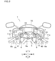
- an input device 12 is provided, while to the left portion of the handlebar unit 7, an input device 13 is provided.
- the input device 12 is located to the left of and adjacent to the throttle holder 10.
- the input device 13 is located to the right of and adjacent to the left grip portion 8b.
- Each of the input devices 12 and 13 is provided with a plurality of switches. The switches of each of the input devices 12 and 13 are operated by a thumb of a hand gripping corresponding one of the grip portions 8a and 8b.
- the input device 12 is provided with a switch 40 of a rotary type, and corresponds to an input device of the present teaching. The detailed structure of the input device 12 will be described later.
- a headlight unit 14 is located higher than the front wheel 2 and forward of the handlebar unit 7.
- a front face of the headlight unit 14 is covered with a front cowling 15.
- a display device 16 is disposed at the top of the headlight unit 14. The display device 16 is located forward of the handlebar unit 7.
- a swingarm 17 is swingably held, at its front end portion, by a rear portion of the vehicle body frame 4. Rear end portions of the swingarm 17 hold the rear wheel 3.
- Each of rear suspensions 18 which absorb shock in the up/down direction connects a portion of the swingarm 17 which is not a swingarm pivot to the vehicle body frame 4.
- an engine 19 is mounted on the vehicle body frame 4, Rearward of the engine 19, there is disposed a transmission (not shown) having a plurality of speed-changing gears. The driving power of the engine 19 is transmitted to the rear wheel 3 via the transmission and a chain 20. To the left of the transmission, there is provided a shift pedal 21 for changing the gears of the transmission.
- a fuel tank 22 and the seat 23 are attached to an upper portion of the vehicle body frame 4.
- the seat 23 is located rearward of the fuel tank 22.
- the fuel tank 22 and the seat 23 are located higher than the engine 19.
- the motorcycle 1 further includes a not-shown controller configured to control operation of each part of the motorcycle 1.
- the controller is coupled to the throttle grip (the right grip portion) 8a, the input devices 12 and 13, and the like.
- the motorcycle 1 further includes a battery (not shown) which supplies power to electronic equipment such as the controller, the display device 16, and various sensors.
- the input device 12 includes a case 30, a rotary push switch 40, a rocker switch 25, and a slide switch 26.
- the rotary push switch 40 is a switch operable through both operations of: a rotational operation in normal and reverse directions; and a pushing operation.
- the rocker switch 25 is a switch operable through the pushing operation.
- the slide switch 26 is a switch operable through a sliding operation. Note that either one or both of the rocker switch 25 and the slide switch 26 may be omitted from the input device 12. Further, instead of the rocker switch 25 or the slide switch 26, the input device 12 may include another switch.
- the case 30 is attached to the outer periphery of the handlebar unit 7.
- the case 30 has a handlebar insertion hole 31 through which the handlebar unit 7 is inserted.
- a portion of the handlebar unit 7 which is located inside the case 30 extends in a direction substantially the same as a longitudinal direction G of the right grip portion 8a (the longitudinal direction is the direction of the length of the right grip portion 8a).
- the case 30 has a box-like shape having two faces each substantially orthogonal to the longitudinal direction G of the right grip portion 8a.
- the case 30 has, on its rear side with respect to the vehicle forward/rearward direction, an angular portion 32 protruding rearward in the vehicle forward/rearward direction.
- the angular portion 32 is located at substantially middle of the case 30 with respect to the up/down direction.
- a flat surface 33 is formed below the angular portion 32.
- the flat surface 33 is inclined with respect to the up/down direction so that the flat surface 33 extends downward and forward in the vehicle forward/rearward direction.
- the longitudinal direction G of the right grip portion 8a extends right-down-rearward from a base end to a distal end of the right grip portion 8a.
- a thumb 50 extended in the longitudinal direction G of the right grip portion 8a while gripping the right grip portion 8a with fingers other than the thumb 50 is referred to as a thumb 50A.
- a direction from a palmar side to a nail of the thumb 50A is referred to as a direction N (a rearward direction according to the present teaching), and a direction opposite to the direction N is referred to as a direction P.
- the direction P and the direction N are orthogonal to a longitudinal direction of the thumb 50A (the longitudinal direction G of the right grip portion 8a) and to a width direction of the thumb 50A.
- the direction P and the direction N are defined herein based on an average manner of gripping.
- the direction P and the direction N are inclined with respect to the vehicle right/left direction and to the vehicle forward/rearward direction.
- a symbol of an encircled middle dot represents a direction from a position farther from a viewer to a position closer to the viewer
- a symbol of an encircled x represents a direction from a position closer to the viewer to a position farther from the viewer.
- a thickness direction of the thumb 50A extended in the longitudinal direction G of the right grip portion 8a while gripping the right grip portion 8a is referred to as a direction PN.
- the flat surface 33 of the case 30 is formed so that the flat surface 33 extends downward and toward the direction P (see FIG. 6 ). Further, each of the angular portion 32 and the flat surface 33 is formed obliquely to the longitudinal direction G of the right grip portion 8a so that each extends toward the direction P and toward the right grip portion 8a (with respect to the longitudinal direction G) (see FIG. 5 ).
- the rotary push switch 40 includes a rotating body 41 and a main body 42.
- the main body 42 is accommodated in the case 30, and secured to an inner surface of the case 30.
- the rotating body 41 is a disc-like member made from materials such as a synthetic resin.
- the rotating body 41 is held by the main body 42 so as to be rotatable about an axis Cr extending in the longitudinal direction G of the right grip portion 8a (hereinafter, referred to as a rotation axis Cr).
- the rotation axis Cr is an axis passing through the center of the rotating body 41.
- the rotating body 41 is held by the main body 42 so as to be movable in a predetermined direction (a direction PUSH in FIG. 6 ) orthogonal to the rotation axis Cr of the rotating body 41.
- the rotation axis Cr of the rotating body 41 is substantially parallel to the longitudinal direction G of the right grip portion 8a when viewed from the direction PN.
- the rotation axis Cr of the rotating body 41 when viewed from the direction orthogonal to the longitudinal direction G of the right grip portion 8a and to the direction PN, the rotation axis Cr of the rotating body 41 is slightly inclined with respect to the longitudinal direction G of the right grip portion 8a.
- the rotation axis Cr of the rotating body 41 is slightly inclined with respect to the longitudinal direction G of the right grip portion 8a so that the rotation axis Cr extends toward the right grip portion 8a and toward the direction P.
- the rotation axis Cr of the rotating body 41 of this embodiment is almost parallel to the longitudinal direction G of the right grip portion 8a, and almost extends in the longitudinal direction G of the right grip portion 8a.
- the rotation axis Cr of the rotating body 41 is substantially parallel to the flat surface 33.
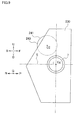
- the rotating body 41 is arranged alongside the handlebar unit 7 in a direction orthogonal to the longitudinal direction G of the right grip portion 8a. As shown in FIG. 6 , a portion of the rotation axis Cr of the rotating body 41 which overlaps the rotating body 41 is referred to as a central portion C0 of the rotating body 41.
- the central portion C0 of the rotating body 41 is positioned toward the direction N, as compared with a central axis Cg of the right grip portion 8a.
- the central portion C0 of the rotating body 41 is positioned lower than a plane S which includes the central axis Cg of the right grip portion 8a and extends in the direction PN.
- the rotating body 41 With respect to a circumferential direction of the rotating body 41, a portion of an outer circumferential surface of the rotating body 41 is accommodated in the case 30, and the remaining portion is exposed to the outside of the case 30. With respect to the width direction, the outer circumferential surface of the rotating body 41 is entirely exposed to the outside of the case 30, in this embodiment. Therefore, the entire outer circumferential surface of the rotating body 41 forms an operational surface 43 operable with the thumb 50. That is, the operational surface 43 extends continuously along the entire circumference of the rotating body 41 without interruption. The exposed portion of the rotating body 41 protrudes from a substantially quadrangular hole formed on the flat surface 33.
- the portion of the operational surface 43 which is exposed to the outside of the case 30 is positioned toward the direction N as compared with the central axis Cg of the right grip portion 8a. Further, the portion of the operational surface 43 which is exposed to the outside of the case 30 is positioned lower than the plane S including the central axis Cg of the right grip portion 8a and extending in the direction PN.
- the rotating body 41 is rotationally operated by swinging the thumb 50 while the palmar side of the thumb 50 of the hand gripping the right grip portion 8a is in contact with the portion of the operational surface 43 which is exposed to the outside of the case 30.
- the third joint of each of the fingers other than the thumb 50 (the third joint from the tip of each finger: MCP joint) may be bent, or not.
- the thumb 50 is swung by pivoting the thumb about its third joint which is located near the wrist. Note that a line 51 in FIG. 7 shows a trajectory of a point at the distal end of the swinging thumb 50.
- the rotating body 41 is operated also by pushing, specifically by pushing the portion of the operational surface 43 which is exposed to the outside of the case 30 in the direction PUSH in FIG. 6 with the palmar side of the thumb 50 of the hand gripping the right grip portion 8a.
- the rotating body 41 is configured to return back to its original position when the thumb 50 pushing the rotating body 41 leaves.
- the outer diameter ⁇ of the rotating body 41 of this embodiment (the diameter of the operational surface 43) (see FIG. 6 ) is at a similar level to the diameter of the handlebar insertion hole 31 and to the diameter of the handlebar unit 7.
- a width W of the operational surface 43 (the width in the direction of the rotation axis Cr) (see FIG. 4 ) is smaller than the radius ( ⁇ /2) of the operational surface 43.
- the length of the portion of the operational surface 43 which is exposed to the outside of the case 30 in the direction orthogonal to the width W when viewed from the direction orthogonal to a plane which directly connects the both circumferential ends of the portion of the operational surface 43 which is exposed to the outside of the case 30 is referred to as a linear length L of the exposed portion of the operational surface 43.
- the circumferential length of the portion of the operational surface 43 which is exposed to the outside of the case 30 is less than a half of the entire circumference of the operational surface 43, and therefore, the linear length L is equal to the distance between the both circumferential ends of the portion of the operational surface 43 which is exposed to the outside of the case 30.
- the width W of the operational surface 43 is smaller than the linear length L of the exposed portion of the operational surface 43.
- An end portion of the operational surface 43 which is farther from the right grip 8a is positioned so that the thumb 50 of the hand gripping the right grip portion 8a reaches there without any difficulty. Further, on both sides of the rotating body 41 in the direction along the rotation axis Cr, there is no protrusion on an outer surface of the case 30. Therefore, as shown in FIG. 5 , it is possible to rotationally operate the rotating body 41 while the palmar side of the thumb 50 is in contact with the end portion (an angular portion) of the operational surface 43 which is farther from the right grip portion 8a.
- the width W of the operational surface 43 is relatively small, it is also possible to operate the rotating body 41 while the palmar side of the thumb 50 is in contact with the end portion (an angular portion) of the operational surface 43 which is closer to the right grip portion 8a. Furthermore, it is a matter of course that the rotating body 41 may be operated while the palmar side of the thumb 50 is in surface contact with the operational surface 43.
- the operational surface 43 is an uneven surface on which recesses 44 and projections are arranged alternately with each other in the circumferential direction (see FIG. 6 ). That is, the recesses 44 and the projections are arranged in a swing direction in which the thumb 50 of the hand gripping the right grip portion 8a is swung.
- the groove width (the largest width) of each recess 44 in the circumferential direction of the operational surface 43 is designed so that the thumb 50 can be pressed onto an edge of the recess 44 while gripping the right grip portion 8a with fingers other than the thumb 50. This enables the thumb 50 to contact the edge of the recess 44 while being caught thereon, to rotationally operate the rotating body 41.
- the recess 44 may be shaped so that a bottom surface of the recess 44 can be touched with the thumb 50, or so that the bottom surface of the recess 44 cannot be touched with the thumb 50. That is, the operational surface 43 may include one or more portions which cannot be touched with the thumb 50.
- each of the small recesses is 0.1 mm to 0.3 mm, for example, but the size is not limited to this.
- the main body 42 of the rotary push switch 40 includes a resistance applying unit 42a, a position detecting unit 42b, and a push detecting unit 42c.
- the resistance applying unit 42a, the position detecting unit 42b, and the push detecting unit 42c in FIG. 6 are illustrated conceptually, and do not show their shapes.
- the resistance applying unit 42a is configured to apply resistance to rotation of the rotating body 41.
- the resistance applying unit 42a is configured to increase/decrease the resistance applied to the rotating body 41 with respect to a rotation direction of the rotating body 41. That is, the resistance applied to the rotating body 41 is increased to the maximum each time the rotating body 41 is rotated a predetermined angle ⁇ . This gives a click feeling to the rotational operation of the rotating body 41, at intervals of the angle ⁇ .
- the angle ⁇ is 30 degrees, for example, but is not limited to this.
- the specific structure of the resistance applying unit 42a is similar to that of the resistance applying unit of a general rotary switch.
- the position detecting unit 42b is configured to detect a rotational angle of the rotating body 41. Further, the position detecting unit 42b is configured to generate a rotational operation signal corresponding to the detected rotational angle and transmit the signal to the controller. The position detecting unit 42b is configured to transmit the rotational operation signal at a rotational angle at which a maximum resistance is applied to the rotating body 41 by the resistance applying unit 42a. The position detecting unit 42b may be configured to transmit the rotational operation signal at intervals of angle ⁇ , or may be configured to transmit the rotational operation signal at intervals of an angle obtained by multiplying the angle ⁇ by a predetermined number.
- the position detecting unit 42b may be configured to detect an angle of consecutive rotations of the rotating body 41.
- an input value transmitted as the rotational operation signal may be proportional to the rotational angle of the consecutive rotations, or may be non-proportional to this.
- the following settings are made, for example: the input value for each angle ⁇ is set to 1 when the angle of the consecutive rotations is the same as or twice or three times as large as the angle ⁇ , and the input value for each angle ⁇ is set to 2 or a number larger than 2 when the angle of the consecutive rotations is four or more times as large as the angle ⁇ .
- the push detecting unit 42c is configured to detect whether the rotating body 41 is operated by pushing. That is, the push detecting unit 42c detects whether the rotating body 41 is moved in the direction PUSH in FIG. 6 . Further, the push detecting unit 42c transmits a push operation signal to the controller when the push detecting unit 42c detects that the rotating body 41 is operated by pushing.
- the specific structures of the position detecting unit 42b and the push detecting unit 42c are respectively similar to those of the position detecting unit and the push detecting unit of a general rotary switch.
- the motorcycle 1 of this embodiment has the following features.
- the input device 12 includes a case 30, and a rotating body 41 including an operational surface 43 arranged in the circumferential direction, a portion of which is accommodated in the case 30 and a remaining portion of which is exposed to the outside of the case 30, the rotating body 41 being rotatable about the axis Cr extending in the longitudinal direction G of the grip portion 8a.
- the rotating body 41 is rotationally operated by swinging the thumb 50 of the hand gripping the grip portion 8a while the palmar side of the thumb 50 is in contact with the portion of the operational surface 43 which is exposed to the outside of the case 30.
- Different rotational angles of the rotating body 41 respectively correspond to different operation amounts to be input. This allows the rotating body 41 to be used for a wider variety of input operations than a push or slide operation member, leading to its good operability.
- the rotating body 41 is operated with the thumb 50, and this improves operability of the rotating body 41.
- the thumb 50 is easily moved while the grip portion 8a is gripped with other fingers, and therefore suitable for operation of the rotating body 41.
- the rotating body 41 having the rotation axis Cr extending in the longitudinal direction G of the grip portion 8a is disposed in the vicinity of a part of the handlebar unit 7 extending in the longitudinal direction G of the grip portion 8a. Accordingly, the larger the outer diameter of the rotating body 41 is, the larger the distance between the handlebar unit 7 and the portion of the operational surface 43 which is exposed to the outside of the case 30.
- the grip portion 8a is gripped with the fingers other than the thumb 50, it is easy to swing the thumb 50 regardless of the distance between the distal end of the thumb 50 and the handlebar unit 7. Therefore, irrespective of the distance between the operational surface 43 and the handlebar unit 7, it is easy to operate the rotating body 41 by swinging the thumb 50.
- the thumb 50 is swung by pivoting the thumb about its third joint located closer to the wrist, and therefore the angle of the range within which the thumb 50 is swung is larger, but it is difficult to slightly move the thumb 50. Therefore, it would be better that the diameter ⁇ of the operational surface 43 (the outer diameter of the rotating body 41) is large to some extent to facilitate operation of the rotating body 41 by swinging the thumb 50.
- the input device 12 of this embodiment has good operability while avoiding interference with the handlebar unit 7. Further, it is possible to increase the operation amount in each operation by increasing the circumferential length of the portion of the operational surface 43 which is exposed to the outside of the case 30.
- the resistance applying unit 42a is configured to increase/decrease the resistance applied to the rotating body 41 with respect to the rotation direction of the rotating body 41 so that a click feeling is given to the rotational operation of the rotating body 41 at intervals of the predetermined angle ⁇ .
- the click feeling given to the rotational operation of the rotating body 41 at intervals of the predetermined angle ⁇ enables the rider to realize that the rotating body 41 has been rotated the angle ⁇ . This facilitates input operations in which a selected item is changed each time the rotating body 41 is rotated the predetermined angle ⁇ , for example.
- the rotating body 41 is easily rotated even though relatively larger resistance is applied to the rotating body 41 since a larger force is exerted thereon from the thumb 50. Therefore, a maximum value of the resistance applied to the rotating body 41 may be increased, thereby to increase the increment/decrement (the difference between the maximum value and the minimum value) of the resistance applied to the rotating body 41. This provides a clearer click feeling to the rotational operation of the rotating body 41.
- the width W of the operational surface 43 is smaller than the linear length L of the exposed portion of the operational surface 43.
- the smaller width W of the operational surface 43 allows a contact area between the thumb 50 and the operational surface 43 to be smaller. This results in a larger pressure per unit area on the contact area between the thumb 50 and the operational surface 43. This helps the rider to realize which portion of the thumb 50 contacts the operational surface 43, thereby further improving usability.
- the smaller width of the operational surface 43 allows the rotating body 41 to be installed in a smaller space. This helps the rotating body 41 not interfere with the handlebar unit 7.
- the entire outer circumferential surface of the rotating body 41 forms the operational surface 43, and a part of each of the both end surfaces crossing the rotation axis Cr of the rotating body 41 is exposed to the outside of the case 30.
- the pressure per unit area on the contact area between the thumb 50 and the operational surface 43 is larger than the case where the rotating body 41 is rotated with the thumb 50 surface-contacting the operational surface 43. This helps the rider to realize which portion of the thumb 50 contacts the operational surface 43, thereby improving usability.
- the rotating body 41 is arranged alongside the handlebar unit 7 in the direction orthogonal to the longitudinal direction G of the grip portion 8a. This offers greater flexibility to the location where the rotating body 41 is provided than in the case where the handlebar unit 7 passes through an inner portion of the rotating body 41. This allows the rotating body 41 to be disposed at a location where the rotating body 41 is operated more easily.
- the above structure increases the freedom in determining the size of the outer diameter of the rotating body 41, compared with the case where the handlebar unit 7 passes through an inner portion of the rotating body 41.
- the operational surface 43 is an uneven surface on which the recesses 44 and the projections are alternately arranged in the swing direction in which the thumb 50 of the hand gripping the grip portion 8a is swung, and a groove width of each recess 44 in the swing direction is designed to enable an edge of a recess 44 to be pushed with the thumb 50 of the hand gripping the grip portion 8a. Therefore, it is possible to rotate the rotating body 41 by swinging the thumb 50 while pushing the edge of the recess 44 (or a surface defining the recess) with the thumb 50. The thumb 50 is thus caught on the recess 44, and this prevents the thumb 50 from slipping in the circumferential direction. This improves operability of the rotating body 41.
- the plurality of small recesses each having the smaller groove width than that of each recess 44 are formed on the operational surface 43 of the rotating body 41. Therefore, when the rotating body 41 is rotated by swinging the thumb 50 while the thumb 50 is in contact with the operational surface 43, the small recesses prevent a slip of the thumb 50 (the slip is not limited to a slip in the circumferential direction of the operational surface 43). This further improves operability of the rotating body 41.
- the rotating body 41 is configured to be operable by pushing the rotating body 41 with the thumb 50 of the hand gripping the grip portion 8a in a predetermined direction orthogonal to the rotation axis Cr of the rotating body 41.
- the rotating body 41 is operable not only through the rotational operation by swinging the thumb 50, but also through the pushing operation, and therefore three or more types of input operations are possible using the single rotating body 41.
- the operational surface 43 is formed into the uneven surface where the recesses 44 and the projections are arranged alternately with each other; however, the shape of the operational surface 43 is not limited to this.
- the operational surface may be formed so that its diameter is constant with respect to the circumferential direction.
- the plurality of small recesses (not shown) each having the smaller groove width than that of each recess 44 are formed on the operational surface 43; however, the small recesses do not have to be formed.
- the outer circumferential surface of the rotating body 41 may be covered with skin made of materials having a high friction coefficient, such as rubber, to serve a non-slip function on the operational surface 43.
- the non-slip function may be provided on the operational surface 43 in any other way.
- the outer diameter ⁇ of the rotating body 41 (the diameter of the operational surface 43), the width W of the rotating body 41 (the width of the operational surface 43), and the linear length L of the exposed portion of the operational surface 43 are not limited to those in the above embodiment, respectively. Provided however, it is preferable that the width W of the operational surface 43 of the rotating body 41 is smaller than the linear length L of the exposed portion of the operational surface 43.
- each linear length L7, L8 of the exposed portion of an operational surface 743, 843 of a rotating body 741, 841 may be larger than the linear length L of the exposed portion of the operational surface 43 of the above embodiment.
- a width W7 of the operational surface 743 in a direction of a rotation axis is smaller than the linear length L7 of the exposed portion of the operational surface 743.
- a width W8 of the operational surface 843 in a direction of a rotation axis is larger than the linear length L8 of the exposed portion of the operational surface 843.
- the thumb 50 used for rotationally operating the rotating body 741, 841 while a portion of the palmar side of the thumb 50 which is near the distal end the thumb 50 is in contact with the operational surface 743, 843 is illustrated with alternate long and two short dashes lines.
- hatched are portions of the operational surface 743, 843 each of which is contacted by the palmar side of the thumb 50 illustrated with the alternate long and two short dashes lines.
- the width of the operational surface of the rotating body is smaller than the linear length of the exposed portion of the operational surface.
- the longer linear length L7, L8 of the exposed portion of the operational surface 743, 843 allows the thumb 50 to move widely to operate the rotating body 741, 841, and this facilitates operation of the rotating body 741, 841 by swinging the thumb 50.
- the increase in the linear length L7, L8 of the exposed portion of the operational surface 743, 843 increases the distance which the distal end of the thumb 50 travels in the longitudinal direction G of the grip portion 8a as the thumb 50 is swung.
- the smaller width W7 of the operational surface 743 results in the smaller contact area between the distal end of the thumb 50 and the operational surface 743.
- the linear length L7 of the exposed portion of the operational surface 743 is larger and the operation amount in each operation is larger, the change in the size of the contact area between the distal end of the thumb 50 and the operational surface 743 is smaller, leading to good usability.
- the width W of the operational surface 43 is smaller than the radius of the operational surface 43 ( ⁇ /2); however, the width W may be larger than the radius ( ⁇ /2). Provided however, it is preferable that the width W of the operational surface 43 is smaller than the diameter ⁇ of the operational surface 43.
- the rotating body 41 is positioned toward the direction N as compared with the portion of the handlebar unit 7 which is located inside the case 30; however, the position of the rotating body 41 is not limited to this. As shown in FIGs. 8 and 9 , for example, an entire rotating body 141, 241 does not have to be positioned toward the direction N as compared with the portion of the handlebar unit 7 which is located inside a case 130, 230, as long as a central portion C 1, C2 of the rotating body 141, 241 is positioned toward the direction N as compared with the central axis Cg of the grip portion 8a.
- the central portion C0 of the rotating body 41 is positioned lower than the plane S including the central axis Cg of the grip portion 8a and extending in the direction PN; however, a variation shown in FIG. 9 , for example, is also possible, in which the central portion C2 of the rotating body 241 is positioned higher than the plane S.
- the portion of the operational surface 43 which is exposed to the outside of the case 30 is positioned lower than the plane S including the central axis Cg of the grip portion 8a and extending in the direction PN; however, a variation shown in FIG. 9 , for example, is also possible, in which a portion of the operational surface 243 which is exposed to the outside of the case 30 is positioned higher than the plane S.
- the surface of the case 30 having the hole for the exposed portion of the rotating body 41 is not limited to the flat surface 33 of the above embodiment which is inclined as described above.
- a surface inclined so that the surface extends upward and toward the direction P may have the hole for the exposed portion of the rotating body 241.
- a surface parallel to the grip portion 8a when viewed from the direction orthogonal to the direction PN and to the longitudinal direction G of the grip portion 8a may have the hole for the exposed portion of the rotating body.
- approximately one fourth of the operational surface 43 with respect to its circumferential length is exposed to the outside of the case 30; however, the length of the exposed portion of the operational surface 43 is not limited to this. For example, a half or more of the operational surface with respect to its circumferential length may be exposed to the outside of the case.
- the rotation axis Cr of the rotating body 41 is almost parallel to the longitudinal direction G of the right grip portion 8a; however, the direction of the rotation axis Cr of the rotating body 41 is not limited to that of the above embodiment as long as it extends substantially in the longitudinal direction G of the grip 8a. That is, the rotation axis Cr of the rotating body 41 may be completely parallel to the longitudinal direction G of the grip portion 8a, or may be inclined with respect to the longitudinal direction G of the grip portion 8a within the range of plus-minus 45 degrees.
- a portion of an operational surface 343 which is exposed to the outside of a case 330 is positioned lower than the central axis Cg of the grip portion 8a when viewed from the direction PN.
- a rotation axis Cr3 of the rotating body 341 may extend upward and toward the grip portion 8a when viewed from the direction PN.
- a portion of an operational surface 443 which is exposed to the outside of a case 430 is positioned higher than the central axis Cg of the grip portion 8a when viewed from the direction PN.
- a rotation axis Cr4 of the rotating body 441 may extend downward and toward the grip portion 8a when viewed from the direction PN.
- the rotation axis Cr of the rotating body 41 may be parallel to the longitudinal direction G of the grip 8a, or may be inclined with respect to the longitudinal direction G of the right grip portion 8a so that the rotation axis Cr extends toward the grip portion 8a and toward the direction N.
- each of the rotating bodies 141, 241, 341, and 441 described above with reference to FIGs. 8 to 11 is a disc-like member similar to the rotating body 41 of the above embodiment, and the rotation axis of each rotating body passes through the center of the rotating body.
- the case 30 is formed so that the both end surfaces of the rotating body 41 in its axial direction are exposed to the outside of the case 30; however, the case 30 may be formed so that one of the axial end surfaces of the rotating body 41 is exposed to the outside of the case 30 and the other end surface is not exposed to the outside of the case 30. Alternatively, the case 30 may be formed so that the both axial end surfaces of the rotating body 41 are not exposed to the outside of the case 30.
- the entire outer circumferential surface of the rotating body 41 forms the operational surface 43 operable with the thumb 50; however, the present teaching is not limited to this structure.
- the following structure is possible: as shown in FIG. 12 , a part of an outer circumferential surface of a rotating body 541 in its axial direction forms an operational surface 543, and the remaining part forms a non-operational surface 545 which is always accommodated in a case 530.
- the diameter of the operational surface 543 is larger than the diameter of the non-operational surface 545.
- the both axial end portions of the rotating body 541 form the non-operational surface 545; however, the non-operational surface may be formed by either one of the axial end portions of the rotating body.
- each of the right and left grip portions 8a and 8b are not limited to those in the above embodiment.
- the thickness direction of the thumb 50A extended in the longitudinal direction G of the grip portion 8a while gripping the grip portion 8a i.e., the direction PN
- the direction PN is inclined with respect to the vehicle forward/rearward direction; however, the direction PN may be parallel to the vehicle forward/rearward direction.
- the rotating body 41 is arranged alongside the handlebar unit 7 in the direction orthogonal to the longitudinal direction G of the grip portion 8a; however, for example as shown in FIG. 13 , the handlebar unit 7 may pass through an inner portion of a rotating body 641.
- the outer diameter of the rotating body 641 is larger than the outer diameter of the handlebar unit 7, the distance between a portion of an operational surface 643 which is exposed to the outside of a case 630 and the handlebar unit 7 is smaller than the case where the rotating body 41 is arranged alongside the handlebar unit 7 as is in the above embodiment.
- a rotation axis Cr6 of the rotating body 641 is parallel to the longitudinal direction G of the grip portion 8a.
- the resistance applying unit 42a of the input device 12 is configured to increase/decrease resistance applied to the rotating body 41 with respect to the rotation direction of the rotating body 41; however, the resistance applying unit may be configured to apply constant resistance to the rotating body 41 irrespective of the rotational angle.
- the rotary push switch 40 is configured to be operable through both of the rotational operation and the pushing operation; however, the switch may be configured to be operable only through the rotational operation. Further, the rotary push switch 40 of this embodiment is configured to be rotatable in the normal and reverse directions; however, the switch may be configured to rotatable in one of these directions.
- the single rotary push switch 40 is included in the input device 12; however, the input device 12 may include two or more rotary push switches 40.
- the above embodiment deals with, as an example, the case where the input device of the present teaching is applied to the input device 12 provided to the right portion of the handlebar unit 7; however, the input device of the present teaching may be applied to the input device 13 provided to the left portion of the handlebar unit 7.
- the handlebar unit 7 has a section of a hollow circle; however, the shape of the section of the handlebar unit of the present teaching is not limited to the circular shape.
- the handlebar unit may have a section of a hollow quadrangle.
- the handlebar unit 7 has clip-on handlebars; however, the handlebar unit of the present teaching may have a one-piece handlebar.
- the clip-on handlebars are handlebars coupled to front forks without a handle crown interposed therebetween.
- the one-piece handlebar is a handlebar directly coupled to a handle crown.
- the motorcycle 1 of the above embodiment is a street motorbike and a motorbike in a narrow sense; however, the saddle type vehicle of the present teaching is not limited to the motorbike in the narrow sense.
- the term "saddle type vehicle” refers to overall vehicles which a rider rides astride a saddle.
- the saddle type vehicle of the present teaching encompasses: two-wheeled motor vehicles (motorbikes in a broad sense), three-wheeled vehicles, four-wheelers (all terrain vehicles (ATV)), water scooters, snowmobiles, and the like.
- the motorbikes in the broad sense include scooters and the like, in addition to the motorbikes in the narrow sense.
Landscapes
- Engineering & Computer Science (AREA)
- Mechanical Engineering (AREA)
- Mechanical Control Devices (AREA)
Abstract
Description
- The present invention relates to a saddle type vehicle including an input device provided to a handlebar unit.
- Conventionally, a saddle type vehicle such as a motorcycle includes a switch device (an input device) located in the vicinity of a grip of a handlebar unit. The switch device is provided with an operation member configured to be operated with a finger which is not used to grip the grip, while the grip is gripped.
- For the switch device of the saddle type vehicle, a variety of operation members have been devised. Examples of these include a push operation member and a slide operation member, as described in Japanese Unexamined Patent Publication No.
2013-028294 1508480 . - The switch device (input device) is provided to the handlebar unit. Therefore it is required that the operation member of the switch device has good operability while avoiding interference with the handlebar unit.
- In view of the above, an object of the present invention is to provide a saddle type vehicle including an input device having good operability while avoiding interference with a handlebar unit. Such an object is achieved by a saddle type vehicle according to
claim 1. - A saddle type vehicle according to a preferred embodiment includes: a handlebar unit provided forward of a seat in a vehicle forward/rearward direction, the seat held by a vehicle body frame; a left grip portion and a right grip portion respectively provided on a left end portion and a right end portion of the handlebar unit; and an input device provided to the handlebar unit, the input device configured to be operable with a palmar side of a thumb of a hand gripping one of the left grip portion and the right grip portion. The input device includes: a case; and a rotating body including an operational surface arranged in a circumferential direction, a portion of which is accommodated in the case and a remaining portion of which is exposed to an outside of the case, the rotating body being rotatable about an axis extending in a longitudinal direction of the corresponding one of the grip portions by swinging the thumb of the hand gripping the one of the grip portions while the palmar side of the thumb is in contact with the portion of the operational surface which is exposed to the outside of the case.
- In this structure, the input device includes the case, and the rotating body including the operational surface arranged in the circumferential direction, a portion of which is accommodated in the case and the remaining portion of which is exposed to the outside of the case, the rotating body being rotatable about the axis extending in the longitudinal direction of the grip portion. This rotating body is rotationally operated by swinging the thumb of the hand gripping the grip portion while the palmar side of the thumb is in contact with the portion of the operational surface which is exposed to the outside of the case.
- Different rotational angles of the rotating body respectively correspond to different operation amounts to be input. This allows the rotating body to be used for a wider variety of input operations than a push or slide operation member, leading to its good operability.
- Further, according to the present teaching, the rotating body is operated with the thumb, and this improves operability of the rotating body. The thumb is easily moved while the grip portion is gripped with other fingers (fingers other than the thumb among five fingers), and therefore suitable for operation of the rotating body.
- However, since the input device is provided to the handlebar unit, it is necessary to avoid interference between the rotating body and the handlebar unit. Therefore, in the case where the rotating body is arranged alongside the handlebar unit, the rotating body having the rotation axis extending in the longitudinal direction of the grip portion is disposed in the vicinity of a part of the handlebar unit extending in the longitudinal direction of the grip portion. Accordingly, the larger the outer diameter of the rotating body is, the larger the distance between the handlebar unit and the portion of the operational surface which is exposed. Note that, in the case where the part of the handlebar unit passes through an inner portion of the rotating body, the outer diameter of the rotating body is larger than the outer diameter of the handlebar unit; however, the distance between the handlebar unit and the portion of the operational surface which is exposed to the outside of the case can be smaller than in the case where the rotating body is arranged alongside the handlebar unit.
- While the grip portion is gripped with the fingers other than the thumb, it is easy to swing the thumb regardless of the distance between the distal end of the thumb and the handlebar unit. Therefore, irrespective of the distance between the operational surface and the handlebar unit, it is easy to operate the rotating body by swinging the thumb.
- Further, the thumb is swung by pivoting the thumb about its third joint (the third joint from the tip of the thumb: CMC joint) located closer to the wrist, and therefore the angle of the range within which the thumb is swung is larger, but it is difficult to slightly move the thumb. Therefore, it would be better that the diameter of the operational surface (the outer diameter of the rotating body) is large to some extent to facilitate operation of the rotating body by swinging the thumb. In this regard, the input device has good operability while avoiding interference with the handlebar unit, according to the present teaching. Further, it is possible to increase the operation amount in each operation by increasing the circumferential length of the portion of the operational surface which is exposed to the outside of the case.
- Note that, according to the present teaching, the axis extending in the longitudinal direction of the grip portion is an axis which falls within the range of plus-minus 45 degrees to the longitudinal direction of the grip portion.
- Further, according to the present teaching and in this Specification, "to grip the grip portion" means that a rider seated on the seat of the saddle type vehicle grips the grip portion in a riding posture.
- Further, according to the present teaching and in this Specification, "the hand gripping the grip portion" includes not only the case where an eminence at the base of the thumb (i.e., thenar) is in contact with the grip portion, but also the case where the thenar is not in contact with the grip portion.
- Furthermore, according to the present teaching and in this Specification, "the thumb is in contact with the operational surface" includes not only the case where the operational surface is touched with a bare hand, but also the case where the operational surface is touched with a gloved hand.
- In the saddle type vehicle of the present teaching, it is preferable that the input device includes a resistance applying unit configured to apply resistance to rotation of the rotating body.
- It is difficult to slightly swing the thumb. Further, while the grip portion is gripped with the fingers other than the thumb, the thumb tends to be stiffened. Therefore, if no resistance is applied to the rotation of the rotating body, there is a possibility that the rotating body is rotated too much to slightly adjust the rotational angle of the rotating body. According to the present teaching, however, resistance is applied to the rotation of the rotating body by the resistance applying unit, and this makes it easier to slightly adjust the rotational angle of the rotating body, thereby improving operability of the rotating body.
- In the saddle type vehicle of the present teaching, it is preferable that the resistance applying unit is configured to increase/decrease the resistance applied to the rotating body with respect to a rotation direction of the rotating body so that a click feeling is given to a rotational operation of the rotating body at intervals of a predetermined angle.
- In this structure, the click feeling is given to the rotational operation of the rotating body at intervals of the predetermined angle, and this enables the rider to realize that the rotating body has been rotated the predetermined angle. This facilitates input operations in which a selected item is changed each time the rotating body is rotated the predetermined angle, for example. Further, the rotating body is easily rotated even though relatively larger resistance is applied to the rotating body since a larger force is exerted thereon by swinging the thumb. Therefore, a maximum value of the resistance applied to the rotating body may be increased, thereby to increase the increment/decrement (the difference between the maximum value and the minimum value) of the resistance applied to the rotating body. This provides a clearer click feeling to the rotational operation of the rotating body.
- In the saddle type vehicle of the present teaching, it is preferable that, in the rotating body, a width of the operational surface in a direction of the axis extending in the longitudinal direction of the one of the grip portions is smaller than a length of the portion of the operational surface which is exposed to the outside of the case in a direction orthogonal to the width when viewed from a direction orthogonal to a plane directly connecting both circumferential ends of the portion of the operational surface which is exposed to the outside of the case.
- Hereinafter, the length of the portion of the operational surface which is exposed to the outside of the case in the direction orthogonal to the width when viewed from the direction orthogonal to the plane directly connecting the both circumferential ends of the portion of the operational surface which is exposed to the outside of the case is referred to as a "linear length of the exposed portion of the operational surface". The longer linear length of the exposed portion of the operational surface allows the thumb to move widely to operate the rotating body, and this facilitates operation of the rotating body by swinging the thumb.
- However, the increase in the linear length of the exposed portion of the operational surface increases the distance which the distal end of the thumb travels in the longitudinal direction of the grip portion as the thumb is swung. Therefore, if the width of the operational surface (the width in the direction of the axis extending in the longitudinal direction of the one of the grip portions) is large, it is more likely that the size of a contact area between the distal end of the thumb and the operational surface changes as the thumb is swung. A great change in the size of the contact area provides the rider with a feeling of strangeness, leading to poor usability. According to the present teaching, however, the width of the operational surface is smaller than the linear length of the exposed portion of the operational surface. The smaller width of the operational surface results in the smaller contact area between the distal end of the thumb and the operational surface. Thus, even if the linear length of the exposed portion of the operational surface is larger and the operation amount in each operation is larger, the change in the size of the contact area between the distal end of the thumb and the operational surface is smaller, leading to good usability.
- Furthermore, the smaller contact area between the thumb and the operational surface results in a larger pressure per unit area on the contact area between the thumb and the operational surface. This helps the rider to realize which portion of the thumb contacts the operational surface, thereby further improving usability.
- Moreover, the smaller width of the operational surface allows the rotating body to be installed in a smaller space. This helps the rotating body not interfere with the handlebar unit.
- In the saddle type vehicle of the present teaching, it is preferable that: an entire outer circumferential surface of the rotating body forms the operational surface; and at least a part of each of both end surfaces of the rotating body, each of which crosses the longitudinal direction of the one of the grip portions, is exposed to the outside of the case.
- In this structure, the entire outer circumferential surface of the rotating body forms the operational surface, and at least a part of each of the both end surfaces of the rotating body, each of which crosses the axis, is exposed to the outside of the case. This makes it possible to rotate the rotating body while the thumb is in contact with an edge of one of the both end surfaces of the rotating body (an edge of the operational surface). In this case, the pressure per unit area on the contact area between the thumb and the operational surface is larger than the case where the rotating body is rotated with the thumb surface-contacting the operational surface. This helps the rider to realize which portion of the thumb contacts the operational surface, thereby improving usability.
- In the saddle type vehicle of the present teaching, it is preferable that the rotating body is arranged alongside the handlebar unit in a direction orthogonal to the longitudinal direction of the one of the grip portions.
- In this structure, the rotating body is arranged alongside the handlebar unit in the direction orthogonal to the longitudinal direction of the one of the grip portions, and this offers greater flexibility to the location where the rotating body is provided than in the case where the handlebar unit passes through an inner portion of the rotating body. This allows the rotating body to be disposed at a location where the rotation body is operated more easily. In addition, the above structure increases the freedom in determining the size of the outer diameter of the rotating body, compared with the case where the handlebar unit passes through an inner portion of the rotating body.
- In the saddle type vehicle of the present teaching, it is preferable that: the operational surface of the rotating body is an uneven surface on which recesses and projections are arranged alternately with each other in a swing direction in which the thumb of the hand gripping the one of the grip portions is swung; and a groove width of each recess in the swing direction is designed to enable an edge of the recess to be pushed with the thumb of the hand gripping the one of the grip portions.
- In this structure, the groove width of each recess, which is formed on the operational surface, in the swing direction of the thumb of the hand gripping the grip portion (i.e., the groove width in the circumferential direction of the operational surface) is designed to enable an edge of the recess to be pushed with the thumb. Therefore, it is possible to rotate the rotating body by swinging the thumb while pushing the edge of the recess (or a surface defining the recess) with the thumb. The thumb is thus caught on the recess, and this prevents the thumb from slipping in the circumferential direction. This improves operability of the rotating body.
- In the saddle type vehicle of the present teaching, it is preferable that a plurality of small recesses each having a groove width smaller than that of each of the recesses are formed on the operational surface of the rotating body.
- In this structure, the plurality of small recesses each having the smaller groove width than that of each of the recesses are formed on the operational surface. Therefore, when the rotating body is rotated by swinging the thumb while the thumb is in contact with the operational surface, the small recesses prevent a slip of the thumb (the slip is not limited to a slip in the circumferential direction of the operational surface). This further improves operability of the rotating body.
- In the saddle type vehicle of the present teaching, it is preferable that the rotating body is configured to be operable by pushing the rotating body with the thumb of the hand gripping the one of the grip portions in a predetermined direction orthogonal to the axis extending in the longitudinal direction of the one of the grip portions.
- In this structure, the rotating body is operable not only through the rotational operation by swinging the thumb, but also through a pushing operation, and therefore three or more types of input operations are possible using the single rotating body.
- In the saddle type vehicle of the present teaching, it is preferable that the portion of the operational surface which is exposed to the outside of the case is positioned rearward of a central axis of the one of the grip portions, assuming that a rearward direction is a direction from the palmar side to a nail of the thumb of the hand gripping the one of the grip portions, with the thumb extended in the longitudinal direction of the one of the grip portions.
- Note that, according to the present teaching and in this Specification, the "direction from the palmar side to the nail of the thumb" refers to a direction from the palmar side to the nail of the thumb in a thickness direction of the thumb orthogonal to a longitudinal direction of the thumb and to a width direction of the thumb.
-
-
FIG. 1 is a side view of a motorcycle of a first preferred embodiment. -
FIG. 2 is a view from a direction of an arrow A ofFIG. 1 . -
FIG. 3 is a perspective view of a right grip portion and an input device with the periphery thereof. -
FIG. 4 is a view of the right grip portion and the input device with the periphery thereof, viewed from a direction P ofFIG. 3 . -
FIG. 5 is a view of the right grip portion and the input device with the periphery thereof, viewed from a direction orthogonal to the direction P ofFIG. 3 and to a longitudinal direction of the right grip portion. -
FIG. 6 is a side view of the input device, viewed from the longitudinal direction of the right grip portion. -
FIG. 7 is a view of the input device operated by swinging a thumb. -
FIG. 8 is a side view of an input device of a motorcycle of another preferred embodiment. -
FIG. 9 is a side view of an input device of a motorcycle of another preferred embodiment. -
FIG. 10 is a view of an input device of a motorcycle of another preferred embodiment, viewed from the direction P. -
FIG. 11 is a view of an input device of a motorcycle of another preferred embodiment, viewed from the direction P. -
FIG. 12 is a schematic sectional view of an input device of a motorcycle of another preferred embodiment. -
FIG. 13 is a side view of an input device of a motorcycle of another preferred embodiment. -
FIG. 14 is a view of an input device of a motorcycle of another preferred embodiment, viewed from the direction P. -
FIG. 15 is a view of an input device of a motorcycle of another preferred embodiment, viewed from the direction P. - The following describes an embodiment of a saddle type vehicle of the present teaching, with reference to a
motorcycle 1, as an example. - As shown in
FIG. 1 , themotorcycle 1 includes a front wheel 2, arear wheel 3, and avehicle body frame 4. Note that, in the following description for the overall structure of themotorcycle 1, a forward/rearward direction and a right/left direction are respectively a forward/rearward direction and a right/left direction, as seen from a rider R seated on a seat 23 (will be described later) of the motorcycle 1 (a vehicle forward/rearward direction and a vehicle right/left direction). An arrow F and an arrow B shown inFIG. 1 andFIGs. 2 ,3 ,5 , and6 which will be referred to later respectively indicate a forward direction and a rearward direction in the vehicle forward/rearward direction. Further, an arrow U and an arrow D shown inFIG. 1 andFIGs. 2 to 4 and 6 which will be referred to later respectively indicate an upward direction and a downward direction of themotorcycle 1. Furthermore, an arrow L and an arrow R shown inFIGs. 2 to 5 which will be referred to later respectively indicate a left direction and a right direction of the vehicle right/left direction. Note that, out of the arrows indicating the directions in each drawing of the present application, bold arrows indicate directions parallel to the surface of the sheet, and unbold arrows indicate directions not parallel to the surface of the sheet. - As shown in
FIG. 2 , ahead pipe 4a is provided to a front portion of thevehicle body frame 4. In thehead pipe 4a, a steering shaft (not shown) is rotatably inserted. Ahandle crown 5 is secured to an upper end of the steering shaft. - The
handle crown 5 has right and left end portions, to which upper end portions offront forks 6 are respectively secured. Lower end portions of thefront forks 6 support the front wheel 2. Each of thefront forks 6 has a suspension (not shown) which absorbs shock in an up/down direction. - A
handlebar unit 7 is secured to the upper end portions of the twofront forks 6. Thehandlebar unit 7 includes two bars. One of the two bars included in thehandlebar unit 7 extends left-down-rearward from the left end portion of thehandle crown 5. The other bar extends right-down-rearward from the right end portion of thehandle crown 5. The respective directions in which the bars of thehandlebar unit 7 extend are not limited to those shown inFIGs. 1 and2 . - A
right grip portion 8a and aleft grip portion 8b are respectively attached to outer peripheries of a left end portion and a right end portion of thehandlebar unit 7. Note that the left end portion of thehandlebar unit 7 is a left end portion of the left bar, and the right end portion of thehandlebar unit 7 is a right end portion of the right bar. - The
right grip portion 8a is a throttle grip. To theright grip portion 8a, connected is throttle wire for adjusting the position of the throttle. Onto thehandlebar unit 7, athrottle holder 10 accommodating the throttle wire is attached adjacent to theright grip portion 8a. Note that thethrottle holder 10 does not have to be provided. - Further, a
brake lever 11 a is attached to a right portion of thehandlebar unit 7, and aclutch lever 11 b is attached to a left portion of thehandlebar unit 7. To thebrake lever 11a, a brake hose is connected. To theclutch lever 11 b, clutch wire for turning on and off a clutch is connected. - To the right portion of the
handlebar unit 7, aninput device 12 is provided, while to the left portion of thehandlebar unit 7, aninput device 13 is provided. Theinput device 12 is located to the left of and adjacent to thethrottle holder 10. Theinput device 13 is located to the right of and adjacent to theleft grip portion 8b. Each of theinput devices input devices grip portions input device 12 is provided with aswitch 40 of a rotary type, and corresponds to an input device of the present teaching. The detailed structure of theinput device 12 will be described later. - A
headlight unit 14 is located higher than the front wheel 2 and forward of thehandlebar unit 7. A front face of theheadlight unit 14 is covered with afront cowling 15. At the top of theheadlight unit 14, adisplay device 16 is disposed. Thedisplay device 16 is located forward of thehandlebar unit 7. - A
swingarm 17 is swingably held, at its front end portion, by a rear portion of thevehicle body frame 4. Rear end portions of theswingarm 17 hold therear wheel 3. Each ofrear suspensions 18 which absorb shock in the up/down direction connects a portion of theswingarm 17 which is not a swingarm pivot to thevehicle body frame 4. - Further, on the
vehicle body frame 4, anengine 19 is mounted. Rearward of theengine 19, there is disposed a transmission (not shown) having a plurality of speed-changing gears. The driving power of theengine 19 is transmitted to therear wheel 3 via the transmission and achain 20. To the left of the transmission, there is provided ashift pedal 21 for changing the gears of the transmission. - Rearward of the
handlebar unit 7, afuel tank 22 and theseat 23 are attached to an upper portion of thevehicle body frame 4. Theseat 23 is located rearward of thefuel tank 22. Thefuel tank 22 and theseat 23 are located higher than theengine 19. - The
motorcycle 1 further includes a not-shown controller configured to control operation of each part of themotorcycle 1. The controller is coupled to the throttle grip (the right grip portion) 8a, theinput devices motorcycle 1 further includes a battery (not shown) which supplies power to electronic equipment such as the controller, thedisplay device 16, and various sensors. - The following describes the detailed structure of the
input device 12. - As shown in
FIGs. 3 to 6 , theinput device 12 includes acase 30, arotary push switch 40, arocker switch 25, and aslide switch 26. Therotary push switch 40 is a switch operable through both operations of: a rotational operation in normal and reverse directions; and a pushing operation. Therocker switch 25 is a switch operable through the pushing operation. Theslide switch 26 is a switch operable through a sliding operation. Note that either one or both of therocker switch 25 and theslide switch 26 may be omitted from theinput device 12. Further, instead of therocker switch 25 or theslide switch 26, theinput device 12 may include another switch. - The
case 30 is attached to the outer periphery of thehandlebar unit 7. Thecase 30 has ahandlebar insertion hole 31 through which thehandlebar unit 7 is inserted. A portion of thehandlebar unit 7 which is located inside thecase 30 extends in a direction substantially the same as a longitudinal direction G of theright grip portion 8a (the longitudinal direction is the direction of the length of theright grip portion 8a). Further, thecase 30 has a box-like shape having two faces each substantially orthogonal to the longitudinal direction G of theright grip portion 8a. - The
case 30 has, on its rear side with respect to the vehicle forward/rearward direction, anangular portion 32 protruding rearward in the vehicle forward/rearward direction. Theangular portion 32 is located at substantially middle of thecase 30 with respect to the up/down direction. Below theangular portion 32, aflat surface 33 is formed. Theflat surface 33 is inclined with respect to the up/down direction so that theflat surface 33 extends downward and forward in the vehicle forward/rearward direction. - In this embodiment, the longitudinal direction G of the
right grip portion 8a extends right-down-rearward from a base end to a distal end of theright grip portion 8a. Now, athumb 50 extended in the longitudinal direction G of theright grip portion 8a while gripping theright grip portion 8a with fingers other than thethumb 50 is referred to as athumb 50A. A direction from a palmar side to a nail of thethumb 50A is referred to as a direction N (a rearward direction according to the present teaching), and a direction opposite to the direction N is referred to as a direction P. The direction P and the direction N are orthogonal to a longitudinal direction of thethumb 50A (the longitudinal direction G of theright grip portion 8a) and to a width direction of thethumb 50A. Although there are some differences in the manner of gripping thegrip portion 8a depending on the physical size and the riding posture of a user, the direction P and the direction N are defined herein based on an average manner of gripping. In this embodiment, the direction P and the direction N are inclined with respect to the vehicle right/left direction and to the vehicle forward/rearward direction. Note that, inFIG. 4 , a symbol of an encircled middle dot represents a direction from a position farther from a viewer to a position closer to the viewer, and a symbol of an encircled x represents a direction from a position closer to the viewer to a position farther from the viewer. A thickness direction of thethumb 50A extended in the longitudinal direction G of theright grip portion 8a while gripping theright grip portion 8a is referred to as a direction PN. - The
flat surface 33 of thecase 30 is formed so that theflat surface 33 extends downward and toward the direction P (seeFIG. 6 ). Further, each of theangular portion 32 and theflat surface 33 is formed obliquely to the longitudinal direction G of theright grip portion 8a so that each extends toward the direction P and toward theright grip portion 8a (with respect to the longitudinal direction G) (seeFIG. 5 ). - The
rotary push switch 40 includes arotating body 41 and amain body 42. Themain body 42 is accommodated in thecase 30, and secured to an inner surface of thecase 30. - The rotating
body 41 is a disc-like member made from materials such as a synthetic resin. The rotatingbody 41 is held by themain body 42 so as to be rotatable about an axis Cr extending in the longitudinal direction G of theright grip portion 8a (hereinafter, referred to as a rotation axis Cr). The rotation axis Cr is an axis passing through the center of therotating body 41. Further, the rotatingbody 41 is held by themain body 42 so as to be movable in a predetermined direction (a direction PUSH inFIG. 6 ) orthogonal to the rotation axis Cr of therotating body 41. - As shown in
FIG. 4 , the rotation axis Cr of therotating body 41 is substantially parallel to the longitudinal direction G of theright grip portion 8a when viewed from the direction PN. Further, as shown inFIG. 5 , when viewed from the direction orthogonal to the longitudinal direction G of theright grip portion 8a and to the direction PN, the rotation axis Cr of therotating body 41 is slightly inclined with respect to the longitudinal direction G of theright grip portion 8a. Specifically, the rotation axis Cr of therotating body 41 is slightly inclined with respect to the longitudinal direction G of theright grip portion 8a so that the rotation axis Cr extends toward theright grip portion 8a and toward the direction P. Thus, the rotation axis Cr of therotating body 41 of this embodiment is almost parallel to the longitudinal direction G of theright grip portion 8a, and almost extends in the longitudinal direction G of theright grip portion 8a. The rotation axis Cr of therotating body 41 is substantially parallel to theflat surface 33. - The rotating
body 41 is arranged alongside thehandlebar unit 7 in a direction orthogonal to the longitudinal direction G of theright grip portion 8a. As shown inFIG. 6 , a portion of the rotation axis Cr of therotating body 41 which overlaps the rotatingbody 41 is referred to as a central portion C0 of therotating body 41. The central portion C0 of therotating body 41 is positioned toward the direction N, as compared with a central axis Cg of theright grip portion 8a. In this embodiment, not only the central portion C0 of therotating body 41, but the entirerotating body 41 is positioned toward the direction N as compared with the portion of thehandlebar unit 7 which is located inside thecase 30. Further, the central portion C0 of therotating body 41 is positioned lower than a plane S which includes the central axis Cg of theright grip portion 8a and extends in the direction PN. - With respect to a circumferential direction of the
rotating body 41, a portion of an outer circumferential surface of therotating body 41 is accommodated in thecase 30, and the remaining portion is exposed to the outside of thecase 30. With respect to the width direction, the outer circumferential surface of therotating body 41 is entirely exposed to the outside of thecase 30, in this embodiment. Therefore, the entire outer circumferential surface of therotating body 41 forms anoperational surface 43 operable with thethumb 50. That is, theoperational surface 43 extends continuously along the entire circumference of therotating body 41 without interruption. The exposed portion of therotating body 41 protrudes from a substantially quadrangular hole formed on theflat surface 33. Therefore, not only the above portion of the outer circumferential surface (operational surface 43) of therotating body 41, but also a part of each of the both axial end surfaces of the rotating body 41 (a part of each of the both end surfaces crossing the longitudinal direction G of theright grip portion 8a) is exposed to the outside of thecase 30. - Approximately one fourth of the
operational surface 43, with respect to its circumferential length, is exposed to the outside of thecase 30. The portion of theoperational surface 43 which is exposed to the outside of thecase 30 is positioned toward the direction N as compared with the central axis Cg of theright grip portion 8a. Further, the portion of theoperational surface 43 which is exposed to the outside of thecase 30 is positioned lower than the plane S including the central axis Cg of theright grip portion 8a and extending in the direction PN. - As shown in
FIG. 7 , the rotatingbody 41 is rotationally operated by swinging thethumb 50 while the palmar side of thethumb 50 of the hand gripping theright grip portion 8a is in contact with the portion of theoperational surface 43 which is exposed to the outside of thecase 30. At this time, the third joint of each of the fingers other than the thumb 50 (the third joint from the tip of each finger: MCP joint) may be bent, or not. Thethumb 50 is swung by pivoting the thumb about its third joint which is located near the wrist. Note that aline 51 inFIG. 7 shows a trajectory of a point at the distal end of the swingingthumb 50. The rotatingbody 41 is operated also by pushing, specifically by pushing the portion of theoperational surface 43 which is exposed to the outside of thecase 30 in the direction PUSH inFIG. 6 with the palmar side of thethumb 50 of the hand gripping theright grip portion 8a. The rotatingbody 41 is configured to return back to its original position when thethumb 50 pushing the rotatingbody 41 leaves. - The outer diameter ø of the
rotating body 41 of this embodiment (the diameter of the operational surface 43) (seeFIG. 6 ) is at a similar level to the diameter of thehandlebar insertion hole 31 and to the diameter of thehandlebar unit 7. A width W of the operational surface 43 (the width in the direction of the rotation axis Cr) (seeFIG. 4 ) is smaller than the radius (ø/2) of theoperational surface 43. As shown inFIG. 6 , the length of the portion of theoperational surface 43 which is exposed to the outside of thecase 30 in the direction orthogonal to the width W when viewed from the direction orthogonal to a plane which directly connects the both circumferential ends of the portion of theoperational surface 43 which is exposed to the outside of thecase 30 is referred to as a linear length L of the exposed portion of theoperational surface 43. In this embodiment, the circumferential length of the portion of theoperational surface 43 which is exposed to the outside of thecase 30 is less than a half of the entire circumference of theoperational surface 43, and therefore, the linear length L is equal to the distance between the both circumferential ends of the portion of theoperational surface 43 which is exposed to the outside of thecase 30. The width W of theoperational surface 43 is smaller than the linear length L of the exposed portion of theoperational surface 43. - An end portion of the
operational surface 43 which is farther from theright grip 8a is positioned so that thethumb 50 of the hand gripping theright grip portion 8a reaches there without any difficulty. Further, on both sides of therotating body 41 in the direction along the rotation axis Cr, there is no protrusion on an outer surface of thecase 30. Therefore, as shown inFIG. 5 , it is possible to rotationally operate therotating body 41 while the palmar side of thethumb 50 is in contact with the end portion (an angular portion) of theoperational surface 43 which is farther from theright grip portion 8a. Further, since the width W of theoperational surface 43 is relatively small, it is also possible to operate therotating body 41 while the palmar side of thethumb 50 is in contact with the end portion (an angular portion) of theoperational surface 43 which is closer to theright grip portion 8a. Furthermore, it is a matter of course that the rotatingbody 41 may be operated while the palmar side of thethumb 50 is in surface contact with theoperational surface 43. - The
operational surface 43 is an uneven surface on which recesses 44 and projections are arranged alternately with each other in the circumferential direction (seeFIG. 6 ). That is, therecesses 44 and the projections are arranged in a swing direction in which thethumb 50 of the hand gripping theright grip portion 8a is swung. The groove width (the largest width) of eachrecess 44 in the circumferential direction of theoperational surface 43 is designed so that thethumb 50 can be pressed onto an edge of therecess 44 while gripping theright grip portion 8a with fingers other than thethumb 50. This enables thethumb 50 to contact the edge of therecess 44 while being caught thereon, to rotationally operate therotating body 41. Therecess 44 may be shaped so that a bottom surface of therecess 44 can be touched with thethumb 50, or so that the bottom surface of therecess 44 cannot be touched with thethumb 50. That is, theoperational surface 43 may include one or more portions which cannot be touched with thethumb 50. - Further, on the
operational surface 43, there are formed a plurality of small recesses (not shown) each having a groove width smaller than that of eachrecess 44. These small recesses function to prevent a slip. The size of each of the small recesses is 0.1 mm to 0.3 mm, for example, but the size is not limited to this. - As shown in
FIG. 6 , themain body 42 of therotary push switch 40 includes aresistance applying unit 42a, aposition detecting unit 42b, and apush detecting unit 42c. Note that theresistance applying unit 42a, theposition detecting unit 42b, and thepush detecting unit 42c inFIG. 6 are illustrated conceptually, and do not show their shapes. - The
resistance applying unit 42a is configured to apply resistance to rotation of therotating body 41. Theresistance applying unit 42a is configured to increase/decrease the resistance applied to therotating body 41 with respect to a rotation direction of therotating body 41. That is, the resistance applied to therotating body 41 is increased to the maximum each time the rotatingbody 41 is rotated a predetermined angle α. This gives a click feeling to the rotational operation of therotating body 41, at intervals of the angle α. The angle α is 30 degrees, for example, but is not limited to this. The specific structure of theresistance applying unit 42a is similar to that of the resistance applying unit of a general rotary switch. - The
position detecting unit 42b is configured to detect a rotational angle of therotating body 41. Further, theposition detecting unit 42b is configured to generate a rotational operation signal corresponding to the detected rotational angle and transmit the signal to the controller. Theposition detecting unit 42b is configured to transmit the rotational operation signal at a rotational angle at which a maximum resistance is applied to therotating body 41 by theresistance applying unit 42a. Theposition detecting unit 42b may be configured to transmit the rotational operation signal at intervals of angle α, or may be configured to transmit the rotational operation signal at intervals of an angle obtained by multiplying the angle α by a predetermined number. - Further, the
position detecting unit 42b may be configured to detect an angle of consecutive rotations of therotating body 41. In this case, an input value transmitted as the rotational operation signal may be proportional to the rotational angle of the consecutive rotations, or may be non-proportional to this. In the non-proportional case, the following settings are made, for example: the input value for each angle α is set to 1 when the angle of the consecutive rotations is the same as or twice or three times as large as the angle α, and the input value for each angle α is set to 2 or a number larger than 2 when the angle of the consecutive rotations is four or more times as large as the angle α. - The
push detecting unit 42c is configured to detect whether the rotatingbody 41 is operated by pushing. That is, thepush detecting unit 42c detects whether the rotatingbody 41 is moved in the direction PUSH inFIG. 6 . Further, thepush detecting unit 42c transmits a push operation signal to the controller when thepush detecting unit 42c detects that the rotatingbody 41 is operated by pushing. The specific structures of theposition detecting unit 42b and thepush detecting unit 42c are respectively similar to those of the position detecting unit and the push detecting unit of a general rotary switch. - The
motorcycle 1 of this embodiment has the following features. - The
input device 12 includes acase 30, and arotating body 41 including anoperational surface 43 arranged in the circumferential direction, a portion of which is accommodated in thecase 30 and a remaining portion of which is exposed to the outside of thecase 30, the rotatingbody 41 being rotatable about the axis Cr extending in the longitudinal direction G of thegrip portion 8a. The rotatingbody 41 is rotationally operated by swinging thethumb 50 of the hand gripping thegrip portion 8a while the palmar side of thethumb 50 is in contact with the portion of theoperational surface 43 which is exposed to the outside of thecase 30. - Different rotational angles of the
rotating body 41 respectively correspond to different operation amounts to be input. This allows the rotatingbody 41 to be used for a wider variety of input operations than a push or slide operation member, leading to its good operability. - Further, in this embodiment, the rotating
body 41 is operated with thethumb 50, and this improves operability of therotating body 41. Thethumb 50 is easily moved while thegrip portion 8a is gripped with other fingers, and therefore suitable for operation of therotating body 41. - However, since the
input device 12 is provided to thehandlebar unit 7, it is necessary to avoid interference between therotating body 41 and thehandlebar unit 7. Therefore, the rotatingbody 41 having the rotation axis Cr extending in the longitudinal direction G of thegrip portion 8a is disposed in the vicinity of a part of thehandlebar unit 7 extending in the longitudinal direction G of thegrip portion 8a. Accordingly, the larger the outer diameter of therotating body 41 is, the larger the distance between thehandlebar unit 7 and the portion of theoperational surface 43 which is exposed to the outside of thecase 30. - While the
grip portion 8a is gripped with the fingers other than thethumb 50, it is easy to swing thethumb 50 regardless of the distance between the distal end of thethumb 50 and thehandlebar unit 7. Therefore, irrespective of the distance between theoperational surface 43 and thehandlebar unit 7, it is easy to operate therotating body 41 by swinging thethumb 50. Further, thethumb 50 is swung by pivoting the thumb about its third joint located closer to the wrist, and therefore the angle of the range within which thethumb 50 is swung is larger, but it is difficult to slightly move thethumb 50. Therefore, it would be better that the diameter ø of the operational surface 43 (the outer diameter of the rotating body 41) is large to some extent to facilitate operation of therotating body 41 by swinging thethumb 50. In this regard, theinput device 12 of this embodiment has good operability while avoiding interference with thehandlebar unit 7. Further, it is possible to increase the operation amount in each operation by increasing the circumferential length of the portion of theoperational surface 43 which is exposed to the outside of thecase 30. - As described above, it is difficult to slightly swing the
thumb 50. Further, while thegrip portion 8a is gripped with the fingers other than thethumb 50, thethumb 50 tends to be stiffened. Therefore, if no resistance is applied to the rotation of therotating body 41, there is a possibility that the rotatingbody 41 is rotated too much to slightly adjust the rotational angle of therotating body 41. In this embodiment, however, resistance is applied to the rotation of therotating body 41 by theresistance applying unit 42a, and this makes it easier to slightly adjust the rotational angle of therotating body 41, thereby improving operability of therotating body 41. - Further, in this embodiment, the
resistance applying unit 42a is configured to increase/decrease the resistance applied to therotating body 41 with respect to the rotation direction of therotating body 41 so that a click feeling is given to the rotational operation of therotating body 41 at intervals of the predetermined angle α. The click feeling given to the rotational operation of therotating body 41 at intervals of the predetermined angle α enables the rider to realize that the rotatingbody 41 has been rotated the angle α. This facilitates input operations in which a selected item is changed each time the rotatingbody 41 is rotated the predetermined angle α, for example. - Further, the rotating
body 41 is easily rotated even though relatively larger resistance is applied to therotating body 41 since a larger force is exerted thereon from thethumb 50. Therefore, a maximum value of the resistance applied to therotating body 41 may be increased, thereby to increase the increment/decrement (the difference between the maximum value and the minimum value) of the resistance applied to therotating body 41. This provides a clearer click feeling to the rotational operation of therotating body 41. - Further, in this embodiment, the width W of the
operational surface 43 is smaller than the linear length L of the exposed portion of theoperational surface 43. The smaller width W of theoperational surface 43 allows a contact area between thethumb 50 and theoperational surface 43 to be smaller. This results in a larger pressure per unit area on the contact area between thethumb 50 and theoperational surface 43. This helps the rider to realize which portion of thethumb 50 contacts theoperational surface 43, thereby further improving usability. - Further, the smaller width of the
operational surface 43 allows the rotatingbody 41 to be installed in a smaller space. This helps therotating body 41 not interfere with thehandlebar unit 7. - Further, in this embodiment, the entire outer circumferential surface of the
rotating body 41 forms theoperational surface 43, and a part of each of the both end surfaces crossing the rotation axis Cr of therotating body 41 is exposed to the outside of thecase 30. This makes it possible to rotate therotating body 41 while thethumb 50 is in contact with an edge of one of the both end surfaces of the rotating body 41 (an edge of the operational surface 43). In this case, the pressure per unit area on the contact area between thethumb 50 and theoperational surface 43 is larger than the case where the rotatingbody 41 is rotated with thethumb 50 surface-contacting theoperational surface 43. This helps the rider to realize which portion of thethumb 50 contacts theoperational surface 43, thereby improving usability. - Further, in this embodiment, the rotating
body 41 is arranged alongside thehandlebar unit 7 in the direction orthogonal to the longitudinal direction G of thegrip portion 8a. This offers greater flexibility to the location where the rotatingbody 41 is provided than in the case where thehandlebar unit 7 passes through an inner portion of therotating body 41. This allows the rotatingbody 41 to be disposed at a location where the rotatingbody 41 is operated more easily. In addition, the above structure increases the freedom in determining the size of the outer diameter of therotating body 41, compared with the case where thehandlebar unit 7 passes through an inner portion of therotating body 41. - Furthermore, in this embodiment, the
operational surface 43 is an uneven surface on which therecesses 44 and the projections are alternately arranged in the swing direction in which thethumb 50 of the hand gripping thegrip portion 8a is swung, and a groove width of eachrecess 44 in the swing direction is designed to enable an edge of arecess 44 to be pushed with thethumb 50 of the hand gripping thegrip portion 8a. Therefore, it is possible to rotate therotating body 41 by swinging thethumb 50 while pushing the edge of the recess 44 (or a surface defining the recess) with thethumb 50. Thethumb 50 is thus caught on therecess 44, and this prevents thethumb 50 from slipping in the circumferential direction. This improves operability of therotating body 41. - Further, in this embodiment, the plurality of small recesses each having the smaller groove width than that of each
recess 44 are formed on theoperational surface 43 of therotating body 41. Therefore, when therotating body 41 is rotated by swinging thethumb 50 while thethumb 50 is in contact with theoperational surface 43, the small recesses prevent a slip of the thumb 50 (the slip is not limited to a slip in the circumferential direction of the operational surface 43). This further improves operability of therotating body 41. - Further, in this embodiment, the rotating
body 41 is configured to be operable by pushing the rotatingbody 41 with thethumb 50 of the hand gripping thegrip portion 8a in a predetermined direction orthogonal to the rotation axis Cr of therotating body 41. Thus, the rotatingbody 41 is operable not only through the rotational operation by swinging thethumb 50, but also through the pushing operation, and therefore three or more types of input operations are possible using the singlerotating body 41. - A preferred embodiment has been described above. However, the present teaching is not limited to the above-described embodiment, and various changes can be made within the scope of the claims. Further, variations which will be described later may be used in combination as needed. Note that the term "preferable" in this specification is non-exclusive, and means "preferable, but not limited to".
- In the above embodiment, the
operational surface 43 is formed into the uneven surface where therecesses 44 and the projections are arranged alternately with each other; however, the shape of theoperational surface 43 is not limited to this. For example, the operational surface may be formed so that its diameter is constant with respect to the circumferential direction. - In the above embodiment, the plurality of small recesses (not shown) each having the smaller groove width than that of each
recess 44 are formed on theoperational surface 43; however, the small recesses do not have to be formed. Further, the outer circumferential surface of therotating body 41 may be covered with skin made of materials having a high friction coefficient, such as rubber, to serve a non-slip function on theoperational surface 43. Alternatively, the non-slip function may be provided on theoperational surface 43 in any other way. - The outer diameter ø of the rotating body 41 (the diameter of the operational surface 43), the width W of the rotating body 41 (the width of the operational surface 43), and the linear length L of the exposed portion of the
operational surface 43 are not limited to those in the above embodiment, respectively. Provided however, it is preferable that the width W of theoperational surface 43 of therotating body 41 is smaller than the linear length L of the exposed portion of theoperational surface 43. - As shown in
FIGs. 14 and15 , for example, each linear length L7, L8 of the exposed portion of anoperational surface rotating body 741, 841 (the distance between the both circumferential ends of a portion of theoperational surface case 730, 830) may be larger than the linear length L of the exposed portion of theoperational surface 43 of the above embodiment. InFIG. 14 , a width W7 of theoperational surface 743 in a direction of a rotation axis is smaller than the linear length L7 of the exposed portion of theoperational surface 743. Meanwhile, inFIG. 15 , a width W8 of theoperational surface 843 in a direction of a rotation axis is larger than the linear length L8 of the exposed portion of theoperational surface 843. Note that, in each ofFIGs. 14 and15 , thethumb 50 used for rotationally operating therotating body thumb 50 which is near the distal end thethumb 50 is in contact with theoperational surface FIGs. 14 and15 , hatched are portions of theoperational surface thumb 50 illustrated with the alternate long and two short dashes lines. - Hereinafter, description will be given for the reason why it is preferable that the width of the operational surface of the rotating body is smaller than the linear length of the exposed portion of the operational surface. As shown in each of
FIGs. 14 and15 , the longer linear length L7, L8 of the exposed portion of theoperational surface thumb 50 to move widely to operate therotating body rotating body thumb 50. However, the increase in the linear length L7, L8 of the exposed portion of theoperational surface thumb 50 travels in the longitudinal direction G of thegrip portion 8a as thethumb 50 is swung. Further, as the thumb is swung, the direction of the tangent line to the contact area between the operational surface and thethumb 50 changes, and this changes the length of the contact area in the circumferential direction. Therefore, if the width W8 of theoperational surface 843 in the direction of the rotation axis is larger as shown inFIG. 15 , it is more likely that a change is caused in the size of the contact area between the distal end of thethumb 50 and theoperational surface 843 as thethumb 50 is swung. A great change in the size of the contact area between the distal end of thethumb 50 and the operational surface provides the rider with a feeling of strangeness, leading to poor usability. However, in the variation ofFIG. 14 , the smaller width W7 of theoperational surface 743 results in the smaller contact area between the distal end of thethumb 50 and theoperational surface 743. Thus, even if the linear length L7 of the exposed portion of theoperational surface 743 is larger and the operation amount in each operation is larger, the change in the size of the contact area between the distal end of thethumb 50 and theoperational surface 743 is smaller, leading to good usability. - In the above embodiment, the width W of the
operational surface 43 is smaller than the radius of the operational surface 43 (ø/2); however, the width W may be larger than the radius (ø/2). Provided however, it is preferable that the width W of theoperational surface 43 is smaller than the diameter ø of theoperational surface 43. - In the above embodiment, the rotating
body 41 is positioned toward the direction N as compared with the portion of thehandlebar unit 7 which is located inside thecase 30; however, the position of therotating body 41 is not limited to this. As shown inFIGs. 8 and9 , for example, an entirerotating body handlebar unit 7 which is located inside acase central portion C 1, C2 of therotating body grip portion 8a. - Further, in the above embodiment, the central portion C0 of the
rotating body 41 is positioned lower than the plane S including the central axis Cg of thegrip portion 8a and extending in the direction PN; however, a variation shown inFIG. 9 , for example, is also possible, in which the central portion C2 of therotating body 241 is positioned higher than the plane S. - Furthermore, in the above embodiment, the portion of the
operational surface 43 which is exposed to the outside of thecase 30 is positioned lower than the plane S including the central axis Cg of thegrip portion 8a and extending in the direction PN; however, a variation shown inFIG. 9 , for example, is also possible, in which a portion of theoperational surface 243 which is exposed to the outside of thecase 30 is positioned higher than the plane S. - The surface of the
case 30 having the hole for the exposed portion of therotating body 41 is not limited to theflat surface 33 of the above embodiment which is inclined as described above. For example, as is in thecase 230 shown inFIG. 9 , a surface inclined so that the surface extends upward and toward the direction P may have the hole for the exposed portion of therotating body 241. Alternatively, for example, a surface parallel to thegrip portion 8a when viewed from the direction orthogonal to the direction PN and to the longitudinal direction G of thegrip portion 8a may have the hole for the exposed portion of the rotating body. - In the above embodiment, approximately one fourth of the
operational surface 43 with respect to its circumferential length is exposed to the outside of thecase 30; however, the length of the exposed portion of theoperational surface 43 is not limited to this. For example, a half or more of the operational surface with respect to its circumferential length may be exposed to the outside of the case. - In the above embodiment, the rotation axis Cr of the
rotating body 41 is almost parallel to the longitudinal direction G of theright grip portion 8a; however, the direction of the rotation axis Cr of therotating body 41 is not limited to that of the above embodiment as long as it extends substantially in the longitudinal direction G of thegrip 8a. That is, the rotation axis Cr of therotating body 41 may be completely parallel to the longitudinal direction G of thegrip portion 8a, or may be inclined with respect to the longitudinal direction G of thegrip portion 8a within the range of plus-minus 45 degrees. - In the case where the rotation axis Cr of the
rotating body 41 inclined with respect to the longitudinal direction G of thegrip portion 8a, it is preferable to determine its inclination angle taking into account the swing direction of thethumb 50. - For example, in the
rotating body 341 shown inFIG. 10 , a portion of anoperational surface 343 which is exposed to the outside of acase 330 is positioned lower than the central axis Cg of thegrip portion 8a when viewed from the direction PN. In this case, a rotation axis Cr3 of therotating body 341 may extend upward and toward thegrip portion 8a when viewed from the direction PN. - Further, for example, in a
rotating body 441 shown inFIG. 11 , a portion of anoperational surface 443 which is exposed to the outside of acase 430 is positioned higher than the central axis Cg of thegrip portion 8a when viewed from the direction PN. In this case, a rotation axis Cr4 of therotating body 441 may extend downward and toward thegrip portion 8a when viewed from the direction PN. - Furthermore, for example, when viewed from the direction orthogonal to the longitudinal direction G of the
right grip portion 8a and to the direction PN, the rotation axis Cr of therotating body 41 may be parallel to the longitudinal direction G of thegrip 8a, or may be inclined with respect to the longitudinal direction G of theright grip portion 8a so that the rotation axis Cr extends toward thegrip portion 8a and toward the direction N. - Note that each of the
rotating bodies FIGs. 8 to 11 is a disc-like member similar to therotating body 41 of the above embodiment, and the rotation axis of each rotating body passes through the center of the rotating body. - In the above embodiment, the
case 30 is formed so that the both end surfaces of therotating body 41 in its axial direction are exposed to the outside of thecase 30; however, thecase 30 may be formed so that one of the axial end surfaces of therotating body 41 is exposed to the outside of thecase 30 and the other end surface is not exposed to the outside of thecase 30. Alternatively, thecase 30 may be formed so that the both axial end surfaces of therotating body 41 are not exposed to the outside of thecase 30. - In the above embodiment, the entire outer circumferential surface of the
rotating body 41 forms theoperational surface 43 operable with thethumb 50; however, the present teaching is not limited to this structure. For example, the following structure is possible: as shown inFIG. 12 , a part of an outer circumferential surface of arotating body 541 in its axial direction forms anoperational surface 543, and the remaining part forms anon-operational surface 545 which is always accommodated in acase 530. The diameter of theoperational surface 543 is larger than the diameter of thenon-operational surface 545. Further, inFIG. 12 , the both axial end portions of therotating body 541 form thenon-operational surface 545; however, the non-operational surface may be formed by either one of the axial end portions of the rotating body. - The position and the direction of each of the right and left
grip portions thumb 50A extended in the longitudinal direction G of thegrip portion 8a while gripping thegrip portion 8a (i.e., the direction PN) is inclined with respect to the vehicle forward/rearward direction; however, the direction PN may be parallel to the vehicle forward/rearward direction. - In the above embodiment, the rotating
body 41 is arranged alongside thehandlebar unit 7 in the direction orthogonal to the longitudinal direction G of thegrip portion 8a; however, for example as shown inFIG. 13 , thehandlebar unit 7 may pass through an inner portion of arotating body 641. In this case, although the outer diameter of therotating body 641 is larger than the outer diameter of thehandlebar unit 7, the distance between a portion of an operational surface 643 which is exposed to the outside of acase 630 and thehandlebar unit 7 is smaller than the case where the rotatingbody 41 is arranged alongside thehandlebar unit 7 as is in the above embodiment. Further, it is preferable that a rotation axis Cr6 of therotating body 641 is parallel to the longitudinal direction G of thegrip portion 8a. - In the above embodiment, the
resistance applying unit 42a of theinput device 12 is configured to increase/decrease resistance applied to therotating body 41 with respect to the rotation direction of therotating body 41; however, the resistance applying unit may be configured to apply constant resistance to therotating body 41 irrespective of the rotational angle. - In the above embodiment, the
rotary push switch 40 is configured to be operable through both of the rotational operation and the pushing operation; however, the switch may be configured to be operable only through the rotational operation. Further, therotary push switch 40 of this embodiment is configured to be rotatable in the normal and reverse directions; however, the switch may be configured to rotatable in one of these directions. - In the above embodiment, the single
rotary push switch 40 is included in theinput device 12; however, theinput device 12 may include two or more rotary push switches 40. - The above embodiment deals with, as an example, the case where the input device of the present teaching is applied to the
input device 12 provided to the right portion of thehandlebar unit 7; however, the input device of the present teaching may be applied to theinput device 13 provided to the left portion of thehandlebar unit 7. - In the above embodiment, the
handlebar unit 7 has a section of a hollow circle; however, the shape of the section of the handlebar unit of the present teaching is not limited to the circular shape. For example, the handlebar unit may have a section of a hollow quadrangle. - In the above embodiment, the
handlebar unit 7 has clip-on handlebars; however, the handlebar unit of the present teaching may have a one-piece handlebar. The clip-on handlebars are handlebars coupled to front forks without a handle crown interposed therebetween. The one-piece handlebar is a handlebar directly coupled to a handle crown. - The
motorcycle 1 of the above embodiment is a street motorbike and a motorbike in a narrow sense; however, the saddle type vehicle of the present teaching is not limited to the motorbike in the narrow sense. It should be noted that the term "saddle type vehicle" refers to overall vehicles which a rider rides astride a saddle. The saddle type vehicle of the present teaching encompasses: two-wheeled motor vehicles (motorbikes in a broad sense), three-wheeled vehicles, four-wheelers (all terrain vehicles (ATV)), water scooters, snowmobiles, and the like. Further, the motorbikes in the broad sense include scooters and the like, in addition to the motorbikes in the narrow sense.
Claims (10)
- A saddle type vehicle (1) comprising:a handlebar unit (7) provided forward of a seat (23) in a vehicle forward/rearward direction, the seat (23) held by a vehicle body frame (4);a left grip portion (8b) and a right grip portion (8a) respectively provided on a left end portion and a right end portion of the handlebar unit (7); andan input device (12) provided to the handlebar unit (7), the input device (12) configured to be operable with a palmar side of a thumb of a hand gripping one of the left grip portion (8b) and the right grip portion (8a);wherein the input device (12) comprises:a case (30); anda rotating body (41) including an operational surface (43) arranged in a circumferential direction, a portion of which is accommodated in the case (30) and a remaining portion of which is exposed to an outside of the case (30), the rotating body (41) being rotatable about an axis (Cr) extending in a longitudinal direction of the corresponding one of the grip portions by swinging the thumb of the hand gripping the one of the grip portions while the palmar side of the thumb is in contact with the portion of the operational surface (43) which is exposed to the outside of the case (30).
- The saddle type vehicle (1) according to claim 1, wherein the input device (12) includes a resistance applying unit (42a) configured to apply resistance to rotation of the rotating body (41).
- The saddle type vehicle (1) according to claim 2, wherein the resistance applying unit (42a) is configured to increase/decrease the resistance applied to the rotating body (41) with respect to a rotation direction of the rotating body (41) so that a click feeling is given to a rotational operation of the rotating body (41) at intervals of a predetermined angle.
- The saddle type vehicle (1) according to any one of claims 1 to 3, wherein in the rotating body (41), a width (W) of the operational surface (43) in a direction of the axis (Cr) extending in the longitudinal direction of the one of the grip portions is smaller than a length (L) of the portion of the operational surface (43) which is exposed to the outside of the case (30) in a direction orthogonal to the width (W) when viewed from a direction orthogonal to a plane directly connecting both circumferential ends of the portion of the operational surface (43) which is exposed to the outside of the case (30).
- The saddle type vehicle (1) according to any one of claims 1 to 4, wherein:an entire outer circumferential surface of the rotating body (41) forms the operational surface (43); andat least a part of each of both end surfaces of the rotating body (41), each of which crosses the longitudinal direction of the one of the grip portions, is exposed to the outside of the case (30).
- The saddle type vehicle (1) according to any one of claims 1 to 5, wherein the rotating body (41) is arranged alongside the handlebar unit (7) in a direction orthogonal to the longitudinal direction of the one of the grip portions.
- The saddle type vehicle (1) according to any one of claims 1 to 6, wherein:the operational surface (43) of the rotating body (41) is an uneven surface on which recesses (44) and projections are arranged alternately with each other in a swing direction in which the thumb of the hand gripping the one of the grip portions is swung; anda groove width of each recess (44) in the swing direction is designed to enable an edge of the recess (44) to be pushed with the thumb of the hand gripping the one of the grip portions.
- The saddle type vehicle (1) according to claim 7, wherein a plurality of small recesses each having a groove width smaller than that of each of the recesses (44) are formed on the operational surface (43) of the rotating body (41).
- The saddle type vehicle (1) according to any one of claims 1 to 8, wherein the rotating body (41) is configured to be operable by pushing the rotating body (41) with the thumb of the hand gripping the one of the grip portions in a predetermined direction orthogonal to the axis (Cr) extending in the longitudinal direction of the one of the grip portions.
- The saddle type vehicle (1) according to any one of claims 1 to 9, wherein the portion of the operational surface (43) which is exposed to the outside of the case (30) is positioned rearward of a central axis of the one of the grip portions, assuming that a rearward direction is a direction from the palmar side to a nail of the thumb of the hand gripping the one of the grip portions, with the thumb extended in the longitudinal direction of the one of the grip portions.
Applications Claiming Priority (1)
| Application Number | Priority Date | Filing Date | Title |
|---|---|---|---|
| JP2013227012A JP2015085854A (en) | 2013-10-31 | 2013-10-31 | Saddle riding type vehicle |
Publications (2)
| Publication Number | Publication Date |
|---|---|
| EP2868560A1 true EP2868560A1 (en) | 2015-05-06 |
| EP2868560B1 EP2868560B1 (en) | 2018-02-21 |
Family
ID=51830212
Family Applications (1)
| Application Number | Title | Priority Date | Filing Date |
|---|---|---|---|
| EP14190389.8A Active EP2868560B1 (en) | 2013-10-31 | 2014-10-27 | Saddle type vehicle |
Country Status (2)
| Country | Link |
|---|---|
| EP (1) | EP2868560B1 (en) |
| JP (1) | JP2015085854A (en) |
Cited By (3)
| Publication number | Priority date | Publication date | Assignee | Title |
|---|---|---|---|---|
| US9771122B1 (en) | 2016-03-23 | 2017-09-26 | Harley-Davidson Motor Company Group, LLC | Motorcycle hand control with optical sensor |
| CN109050742A (en) * | 2018-07-28 | 2018-12-21 | 重庆隆鑫机车有限公司 | Motorcycle instrument mounting structure and its motorcycle |
| WO2021105967A3 (en) * | 2019-11-29 | 2021-07-08 | Bombardier Recreational Products Inc. | Switch assembly for mounting to a handlebar of a vehicle |
Families Citing this family (3)
| Publication number | Priority date | Publication date | Assignee | Title |
|---|---|---|---|---|
| JP6855516B2 (en) * | 2019-01-25 | 2021-04-07 | 本田技研工業株式会社 | Saddle-riding vehicle |
| JP2024020898A (en) * | 2022-08-02 | 2024-02-15 | カワサキモータース株式会社 | vehicle |
| WO2024161902A1 (en) * | 2023-01-31 | 2024-08-08 | 本田技研工業株式会社 | Handlebar switch |
Citations (7)
| Publication number | Priority date | Publication date | Assignee | Title |
|---|---|---|---|---|
| US4710599A (en) * | 1985-04-30 | 1987-12-01 | Honda Giken Kogyo Kabushiki Kaisha | Switch attachment structure for use on motor vehicles with handlebars |
| EP1323955A1 (en) * | 2001-12-21 | 2003-07-02 | Ducati Motor Holding S.p.A. | An ergonomic manual switch arrangement for motorcycles |
| EP1508480A2 (en) | 2003-08-21 | 2005-02-23 | Bayerische Motoren Werke Aktiengesellschaft | Display device for motorcycle |
| EP1582452A2 (en) * | 2004-03-29 | 2005-10-05 | Shimano Inc. | Electrical bicycle shift control device |
| US20050274562A1 (en) * | 2004-06-14 | 2005-12-15 | Asahi Denso Co., Ltd. | Switch device |
| US20060248975A1 (en) * | 2004-03-26 | 2006-11-09 | Bayerische Motoren Werke Aktiengesellschaft | Operating element |
| JP2013028294A (en) | 2011-07-29 | 2013-02-07 | Kawasaki Heavy Ind Ltd | Controller for vehicle, vehicle with controller, and control method thereof |
Family Cites Families (3)
| Publication number | Priority date | Publication date | Assignee | Title |
|---|---|---|---|---|
| GB2321682B (en) * | 1997-02-01 | 2001-02-14 | Automotive Products Plc | A braking system |
| US6453764B1 (en) * | 2000-03-03 | 2002-09-24 | Shimano, Inc. | Switch style bicycle shift control device |
| WO2007130360A2 (en) * | 2006-05-01 | 2007-11-15 | Evett Joel W | Bicycle transmission shift control apparatus |
-
2013
- 2013-10-31 JP JP2013227012A patent/JP2015085854A/en active Pending
-
2014
- 2014-10-27 EP EP14190389.8A patent/EP2868560B1/en active Active
Patent Citations (7)
| Publication number | Priority date | Publication date | Assignee | Title |
|---|---|---|---|---|
| US4710599A (en) * | 1985-04-30 | 1987-12-01 | Honda Giken Kogyo Kabushiki Kaisha | Switch attachment structure for use on motor vehicles with handlebars |
| EP1323955A1 (en) * | 2001-12-21 | 2003-07-02 | Ducati Motor Holding S.p.A. | An ergonomic manual switch arrangement for motorcycles |
| EP1508480A2 (en) | 2003-08-21 | 2005-02-23 | Bayerische Motoren Werke Aktiengesellschaft | Display device for motorcycle |
| US20060248975A1 (en) * | 2004-03-26 | 2006-11-09 | Bayerische Motoren Werke Aktiengesellschaft | Operating element |
| EP1582452A2 (en) * | 2004-03-29 | 2005-10-05 | Shimano Inc. | Electrical bicycle shift control device |
| US20050274562A1 (en) * | 2004-06-14 | 2005-12-15 | Asahi Denso Co., Ltd. | Switch device |
| JP2013028294A (en) | 2011-07-29 | 2013-02-07 | Kawasaki Heavy Ind Ltd | Controller for vehicle, vehicle with controller, and control method thereof |
Cited By (5)
| Publication number | Priority date | Publication date | Assignee | Title |
|---|---|---|---|---|
| US9771122B1 (en) | 2016-03-23 | 2017-09-26 | Harley-Davidson Motor Company Group, LLC | Motorcycle hand control with optical sensor |
| CN109050742A (en) * | 2018-07-28 | 2018-12-21 | 重庆隆鑫机车有限公司 | Motorcycle instrument mounting structure and its motorcycle |
| CN109050742B (en) * | 2018-07-28 | 2023-08-25 | 重庆隆鑫机车有限公司 | Motorcycle instrument mounting structure and motorcycle thereof |
| WO2021105967A3 (en) * | 2019-11-29 | 2021-07-08 | Bombardier Recreational Products Inc. | Switch assembly for mounting to a handlebar of a vehicle |
| US12202568B2 (en) | 2019-11-29 | 2025-01-21 | Bombardier Recreational Products Inc. | Switch assembly for mounting to a handlebar of a vehicle |
Also Published As
| Publication number | Publication date |
|---|---|
| JP2015085854A (en) | 2015-05-07 |
| EP2868560B1 (en) | 2018-02-21 |
Similar Documents
| Publication | Publication Date | Title |
|---|---|---|
| EP2868560B1 (en) | Saddle type vehicle | |
| US10647381B2 (en) | Display unit and electric bicycle | |
| CN112918613B (en) | bicycle derailleur | |
| TWI331112B (en) | ||
| EP2868559B1 (en) | Saddle type vehicle | |
| EP2098444A1 (en) | Handlebar grip | |
| JPH0858414A (en) | Grip of manually rotatable type gear shifter for bicycle use | |
| TWM518666U (en) | Bicycle handle and brake shifting group | |
| CN1246179C (en) | Elongated rotatable handgrip | |
| US20190005783A1 (en) | Operating device for operating an electrical bicycle component | |
| TWI901669B (en) | Operating device for human-powered vehicle | |
| US20040045132A1 (en) | Ergonomic handle for bicycle | |
| JP4828254B2 (en) | Shift switch for vehicles with rod-like handles | |
| US20050241428A1 (en) | Cross racing bike front brake lever | |
| CN109552530B (en) | Bicycle control device | |
| TWI784151B (en) | Operating device and operating system | |
| EP4092706B1 (en) | Handle switch and straddled vehicle | |
| US20080163719A1 (en) | Handlebar palm support | |
| US20040168538A1 (en) | Twist grip for operating a bicycle transmission | |
| JP2022138082A (en) | Occupant operation member of motor vehicle | |
| CN100545030C (en) | Bicycle handle | |
| JP6236196B2 (en) | Control lever and operating device for bicycle bar end type gear shift unit | |
| WO2025052766A1 (en) | Steering input device and steer-by-wire-type steering device | |
| KR100839017B1 (en) | Bicycle Handle Assembly | |
| US20140165769A1 (en) | Brake lever |
Legal Events
| Date | Code | Title | Description |
|---|---|---|---|
| PUAI | Public reference made under article 153(3) epc to a published international application that has entered the european phase |
Free format text: ORIGINAL CODE: 0009012 |
|
| 17P | Request for examination filed |
Effective date: 20141027 |
|
| AK | Designated contracting states |
Kind code of ref document: A1 Designated state(s): AL AT BE BG CH CY CZ DE DK EE ES FI FR GB GR HR HU IE IS IT LI LT LU LV MC MK MT NL NO PL PT RO RS SE SI SK SM TR |
|
| AX | Request for extension of the european patent |
Extension state: BA ME |
|
| R17P | Request for examination filed (corrected) |
Effective date: 20151104 |
|
| RBV | Designated contracting states (corrected) |
Designated state(s): AL AT BE BG CH CY CZ DE DK EE ES FI FR GB GR HR HU IE IS IT LI LT LU LV MC MK MT NL NO PL PT RO RS SE SI SK SM TR |
|
| 17Q | First examination report despatched |
Effective date: 20160311 |
|
| GRAP | Despatch of communication of intention to grant a patent |
Free format text: ORIGINAL CODE: EPIDOSNIGR1 |
|
| INTG | Intention to grant announced |
Effective date: 20171012 |
|
| GRAS | Grant fee paid |
Free format text: ORIGINAL CODE: EPIDOSNIGR3 |
|
| GRAA | (expected) grant |
Free format text: ORIGINAL CODE: 0009210 |
|
| AK | Designated contracting states |
Kind code of ref document: B1 Designated state(s): AL AT BE BG CH CY CZ DE DK EE ES FI FR GB GR HR HU IE IS IT LI LT LU LV MC MK MT NL NO PL PT RO RS SE SI SK SM TR |
|
| REG | Reference to a national code |
Ref country code: GB Ref legal event code: FG4D |
|
| REG | Reference to a national code |
Ref country code: CH Ref legal event code: EP |
|
| REG | Reference to a national code |
Ref country code: AT Ref legal event code: REF Ref document number: 971400 Country of ref document: AT Kind code of ref document: T Effective date: 20180315 |
|
| REG | Reference to a national code |
Ref country code: IE Ref legal event code: FG4D |
|
| REG | Reference to a national code |
Ref country code: DE Ref legal event code: R096 Ref document number: 602014021144 Country of ref document: DE |
|
| REG | Reference to a national code |
Ref country code: NL Ref legal event code: MP Effective date: 20180221 |
|
| REG | Reference to a national code |
Ref country code: LT Ref legal event code: MG4D |
|
| REG | Reference to a national code |
Ref country code: AT Ref legal event code: MK05 Ref document number: 971400 Country of ref document: AT Kind code of ref document: T Effective date: 20180221 |
|
| PG25 | Lapsed in a contracting state [announced via postgrant information from national office to epo] |
Ref country code: NO Free format text: LAPSE BECAUSE OF FAILURE TO SUBMIT A TRANSLATION OF THE DESCRIPTION OR TO PAY THE FEE WITHIN THE PRESCRIBED TIME-LIMIT Effective date: 20180521 Ref country code: FI Free format text: LAPSE BECAUSE OF FAILURE TO SUBMIT A TRANSLATION OF THE DESCRIPTION OR TO PAY THE FEE WITHIN THE PRESCRIBED TIME-LIMIT Effective date: 20180221 Ref country code: LT Free format text: LAPSE BECAUSE OF FAILURE TO SUBMIT A TRANSLATION OF THE DESCRIPTION OR TO PAY THE FEE WITHIN THE PRESCRIBED TIME-LIMIT Effective date: 20180221 Ref country code: CY Free format text: LAPSE BECAUSE OF FAILURE TO SUBMIT A TRANSLATION OF THE DESCRIPTION OR TO PAY THE FEE WITHIN THE PRESCRIBED TIME-LIMIT Effective date: 20180221 Ref country code: HR Free format text: LAPSE BECAUSE OF FAILURE TO SUBMIT A TRANSLATION OF THE DESCRIPTION OR TO PAY THE FEE WITHIN THE PRESCRIBED TIME-LIMIT Effective date: 20180221 Ref country code: NL Free format text: LAPSE BECAUSE OF FAILURE TO SUBMIT A TRANSLATION OF THE DESCRIPTION OR TO PAY THE FEE WITHIN THE PRESCRIBED TIME-LIMIT Effective date: 20180221 Ref country code: ES Free format text: LAPSE BECAUSE OF FAILURE TO SUBMIT A TRANSLATION OF THE DESCRIPTION OR TO PAY THE FEE WITHIN THE PRESCRIBED TIME-LIMIT Effective date: 20180221 |
|
| PG25 | Lapsed in a contracting state [announced via postgrant information from national office to epo] |
Ref country code: GR Free format text: LAPSE BECAUSE OF FAILURE TO SUBMIT A TRANSLATION OF THE DESCRIPTION OR TO PAY THE FEE WITHIN THE PRESCRIBED TIME-LIMIT Effective date: 20180522 Ref country code: BG Free format text: LAPSE BECAUSE OF FAILURE TO SUBMIT A TRANSLATION OF THE DESCRIPTION OR TO PAY THE FEE WITHIN THE PRESCRIBED TIME-LIMIT Effective date: 20180521 Ref country code: RS Free format text: LAPSE BECAUSE OF FAILURE TO SUBMIT A TRANSLATION OF THE DESCRIPTION OR TO PAY THE FEE WITHIN THE PRESCRIBED TIME-LIMIT Effective date: 20180221 Ref country code: LV Free format text: LAPSE BECAUSE OF FAILURE TO SUBMIT A TRANSLATION OF THE DESCRIPTION OR TO PAY THE FEE WITHIN THE PRESCRIBED TIME-LIMIT Effective date: 20180221 Ref country code: SE Free format text: LAPSE BECAUSE OF FAILURE TO SUBMIT A TRANSLATION OF THE DESCRIPTION OR TO PAY THE FEE WITHIN THE PRESCRIBED TIME-LIMIT Effective date: 20180221 Ref country code: AT Free format text: LAPSE BECAUSE OF FAILURE TO SUBMIT A TRANSLATION OF THE DESCRIPTION OR TO PAY THE FEE WITHIN THE PRESCRIBED TIME-LIMIT Effective date: 20180221 |
|
| REG | Reference to a national code |
Ref country code: FR Ref legal event code: PLFP Year of fee payment: 5 |
|
| PG25 | Lapsed in a contracting state [announced via postgrant information from national office to epo] |
Ref country code: RO Free format text: LAPSE BECAUSE OF FAILURE TO SUBMIT A TRANSLATION OF THE DESCRIPTION OR TO PAY THE FEE WITHIN THE PRESCRIBED TIME-LIMIT Effective date: 20180221 Ref country code: EE Free format text: LAPSE BECAUSE OF FAILURE TO SUBMIT A TRANSLATION OF THE DESCRIPTION OR TO PAY THE FEE WITHIN THE PRESCRIBED TIME-LIMIT Effective date: 20180221 Ref country code: AL Free format text: LAPSE BECAUSE OF FAILURE TO SUBMIT A TRANSLATION OF THE DESCRIPTION OR TO PAY THE FEE WITHIN THE PRESCRIBED TIME-LIMIT Effective date: 20180221 Ref country code: PL Free format text: LAPSE BECAUSE OF FAILURE TO SUBMIT A TRANSLATION OF THE DESCRIPTION OR TO PAY THE FEE WITHIN THE PRESCRIBED TIME-LIMIT Effective date: 20180221 |
|
| REG | Reference to a national code |
Ref country code: DE Ref legal event code: R097 Ref document number: 602014021144 Country of ref document: DE |
|
| PG25 | Lapsed in a contracting state [announced via postgrant information from national office to epo] |
Ref country code: DK Free format text: LAPSE BECAUSE OF FAILURE TO SUBMIT A TRANSLATION OF THE DESCRIPTION OR TO PAY THE FEE WITHIN THE PRESCRIBED TIME-LIMIT Effective date: 20180221 Ref country code: SK Free format text: LAPSE BECAUSE OF FAILURE TO SUBMIT A TRANSLATION OF THE DESCRIPTION OR TO PAY THE FEE WITHIN THE PRESCRIBED TIME-LIMIT Effective date: 20180221 Ref country code: SM Free format text: LAPSE BECAUSE OF FAILURE TO SUBMIT A TRANSLATION OF THE DESCRIPTION OR TO PAY THE FEE WITHIN THE PRESCRIBED TIME-LIMIT Effective date: 20180221 Ref country code: CZ Free format text: LAPSE BECAUSE OF FAILURE TO SUBMIT A TRANSLATION OF THE DESCRIPTION OR TO PAY THE FEE WITHIN THE PRESCRIBED TIME-LIMIT Effective date: 20180221 |
|
| PLBE | No opposition filed within time limit |
Free format text: ORIGINAL CODE: 0009261 |
|
| STAA | Information on the status of an ep patent application or granted ep patent |
Free format text: STATUS: NO OPPOSITION FILED WITHIN TIME LIMIT |
|
| 26N | No opposition filed |
Effective date: 20181122 |
|
| PG25 | Lapsed in a contracting state [announced via postgrant information from national office to epo] |
Ref country code: SI Free format text: LAPSE BECAUSE OF FAILURE TO SUBMIT A TRANSLATION OF THE DESCRIPTION OR TO PAY THE FEE WITHIN THE PRESCRIBED TIME-LIMIT Effective date: 20180221 |
|
| REG | Reference to a national code |
Ref country code: CH Ref legal event code: PL |
|
| GBPC | Gb: european patent ceased through non-payment of renewal fee |
Effective date: 20181027 |
|
| REG | Reference to a national code |
Ref country code: BE Ref legal event code: MM Effective date: 20181031 |
|
| PG25 | Lapsed in a contracting state [announced via postgrant information from national office to epo] |
Ref country code: LU Free format text: LAPSE BECAUSE OF NON-PAYMENT OF DUE FEES Effective date: 20181027 Ref country code: MC Free format text: LAPSE BECAUSE OF FAILURE TO SUBMIT A TRANSLATION OF THE DESCRIPTION OR TO PAY THE FEE WITHIN THE PRESCRIBED TIME-LIMIT Effective date: 20180221 |
|
| REG | Reference to a national code |
Ref country code: IE Ref legal event code: MM4A |
|
| PG25 | Lapsed in a contracting state [announced via postgrant information from national office to epo] |
Ref country code: LI Free format text: LAPSE BECAUSE OF NON-PAYMENT OF DUE FEES Effective date: 20181031 Ref country code: CH Free format text: LAPSE BECAUSE OF NON-PAYMENT OF DUE FEES Effective date: 20181031 Ref country code: BE Free format text: LAPSE BECAUSE OF NON-PAYMENT OF DUE FEES Effective date: 20181031 |
|
| PG25 | Lapsed in a contracting state [announced via postgrant information from national office to epo] |
Ref country code: IE Free format text: LAPSE BECAUSE OF NON-PAYMENT OF DUE FEES Effective date: 20181027 Ref country code: GB Free format text: LAPSE BECAUSE OF NON-PAYMENT OF DUE FEES Effective date: 20181027 |
|
| PG25 | Lapsed in a contracting state [announced via postgrant information from national office to epo] |
Ref country code: MT Free format text: LAPSE BECAUSE OF NON-PAYMENT OF DUE FEES Effective date: 20181027 |
|
| PG25 | Lapsed in a contracting state [announced via postgrant information from national office to epo] |
Ref country code: TR Free format text: LAPSE BECAUSE OF FAILURE TO SUBMIT A TRANSLATION OF THE DESCRIPTION OR TO PAY THE FEE WITHIN THE PRESCRIBED TIME-LIMIT Effective date: 20180221 |
|
| PG25 | Lapsed in a contracting state [announced via postgrant information from national office to epo] |
Ref country code: PT Free format text: LAPSE BECAUSE OF FAILURE TO SUBMIT A TRANSLATION OF THE DESCRIPTION OR TO PAY THE FEE WITHIN THE PRESCRIBED TIME-LIMIT Effective date: 20180221 |
|
| PG25 | Lapsed in a contracting state [announced via postgrant information from national office to epo] |
Ref country code: HU Free format text: LAPSE BECAUSE OF FAILURE TO SUBMIT A TRANSLATION OF THE DESCRIPTION OR TO PAY THE FEE WITHIN THE PRESCRIBED TIME-LIMIT; INVALID AB INITIO Effective date: 20141027 Ref country code: MK Free format text: LAPSE BECAUSE OF NON-PAYMENT OF DUE FEES Effective date: 20180221 |
|
| PG25 | Lapsed in a contracting state [announced via postgrant information from national office to epo] |
Ref country code: IS Free format text: LAPSE BECAUSE OF FAILURE TO SUBMIT A TRANSLATION OF THE DESCRIPTION OR TO PAY THE FEE WITHIN THE PRESCRIBED TIME-LIMIT Effective date: 20180621 |
|
| P01 | Opt-out of the competence of the unified patent court (upc) registered |
Effective date: 20230527 |
|
| PGFP | Annual fee paid to national office [announced via postgrant information from national office to epo] |
Ref country code: DE Payment date: 20251021 Year of fee payment: 12 |
|
| PGFP | Annual fee paid to national office [announced via postgrant information from national office to epo] |
Ref country code: IT Payment date: 20251024 Year of fee payment: 12 |
|
| PGFP | Annual fee paid to national office [announced via postgrant information from national office to epo] |
Ref country code: FR Payment date: 20251030 Year of fee payment: 12 |