EP2868373A1 - A device for controlling a chemical reaction by a magnetic field and use of said device. - Google Patents
A device for controlling a chemical reaction by a magnetic field and use of said device. Download PDFInfo
- Publication number
- EP2868373A1 EP2868373A1 EP20130306516 EP13306516A EP2868373A1 EP 2868373 A1 EP2868373 A1 EP 2868373A1 EP 20130306516 EP20130306516 EP 20130306516 EP 13306516 A EP13306516 A EP 13306516A EP 2868373 A1 EP2868373 A1 EP 2868373A1
- Authority
- EP
- European Patent Office
- Prior art keywords
- electrodes
- magnetic field
- electrode
- ferromagnetic material
- external magnetic
- Prior art date
- Legal status (The legal status is an assumption and is not a legal conclusion. Google has not performed a legal analysis and makes no representation as to the accuracy of the status listed.)
- Withdrawn
Links
- 230000005291 magnetic effect Effects 0.000 title claims abstract description 115
- 238000006243 chemical reaction Methods 0.000 title claims abstract description 36
- 239000003302 ferromagnetic material Substances 0.000 claims abstract description 39
- 230000005298 paramagnetic effect Effects 0.000 claims abstract description 23
- 230000005415 magnetization Effects 0.000 claims abstract description 22
- 230000006698 induction Effects 0.000 claims abstract description 7
- 230000008859 change Effects 0.000 claims description 16
- 229910052751 metal Inorganic materials 0.000 claims description 5
- 239000002184 metal Substances 0.000 claims description 5
- 239000000463 material Substances 0.000 claims description 3
- 229910052693 Europium Inorganic materials 0.000 claims description 2
- 229910052688 Gadolinium Inorganic materials 0.000 claims description 2
- 229910052772 Samarium Inorganic materials 0.000 claims description 2
- 229910052761 rare earth metal Inorganic materials 0.000 claims description 2
- 150000002910 rare earth metals Chemical class 0.000 claims description 2
- 229910001092 metal group alloy Inorganic materials 0.000 claims 1
- 230000005294 ferromagnetic effect Effects 0.000 abstract description 18
- PXHVJJICTQNCMI-UHFFFAOYSA-N Nickel Chemical compound [Ni] PXHVJJICTQNCMI-UHFFFAOYSA-N 0.000 description 26
- 150000002500 ions Chemical class 0.000 description 19
- 241000894007 species Species 0.000 description 16
- 238000004088 simulation Methods 0.000 description 11
- 238000000034 method Methods 0.000 description 9
- 239000003792 electrolyte Substances 0.000 description 7
- CXQXSVUQTKDNFP-UHFFFAOYSA-N octamethyltrisiloxane Chemical group C[Si](C)(C)O[Si](C)(C)O[Si](C)(C)C CXQXSVUQTKDNFP-UHFFFAOYSA-N 0.000 description 7
- -1 Ni2+ ions Chemical class 0.000 description 6
- 239000004205 dimethyl polysiloxane Substances 0.000 description 6
- 235000013870 dimethyl polysiloxane Nutrition 0.000 description 6
- XEEYBQQBJWHFJM-UHFFFAOYSA-N iron Substances [Fe] XEEYBQQBJWHFJM-UHFFFAOYSA-N 0.000 description 6
- 238000004987 plasma desorption mass spectroscopy Methods 0.000 description 6
- 229920000435 poly(dimethylsiloxane) Polymers 0.000 description 6
- 239000000047 product Substances 0.000 description 6
- 238000004364 calculation method Methods 0.000 description 5
- 238000004519 manufacturing process Methods 0.000 description 5
- 229910018979 CoPt Inorganic materials 0.000 description 4
- VYPSYNLAJGMNEJ-UHFFFAOYSA-N Silicium dioxide Chemical compound O=[Si]=O VYPSYNLAJGMNEJ-UHFFFAOYSA-N 0.000 description 4
- QVGXLLKOCUKJST-UHFFFAOYSA-N atomic oxygen Chemical compound [O] QVGXLLKOCUKJST-UHFFFAOYSA-N 0.000 description 4
- 239000000696 magnetic material Substances 0.000 description 4
- 239000002073 nanorod Substances 0.000 description 4
- 229910052759 nickel Inorganic materials 0.000 description 4
- 239000001301 oxygen Substances 0.000 description 4
- 229910052760 oxygen Inorganic materials 0.000 description 4
- 230000008569 process Effects 0.000 description 4
- 150000003254 radicals Chemical class 0.000 description 4
- 238000006722 reduction reaction Methods 0.000 description 4
- 239000000126 substance Substances 0.000 description 4
- 230000008901 benefit Effects 0.000 description 3
- 238000013461 design Methods 0.000 description 3
- 238000002474 experimental method Methods 0.000 description 3
- 229910052742 iron Inorganic materials 0.000 description 3
- 230000009467 reduction Effects 0.000 description 3
- 238000004804 winding Methods 0.000 description 3
- CSCPPACGZOOCGX-UHFFFAOYSA-N Acetone Chemical compound CC(C)=O CSCPPACGZOOCGX-UHFFFAOYSA-N 0.000 description 2
- XUIMIQQOPSSXEZ-UHFFFAOYSA-N Silicon Chemical compound [Si] XUIMIQQOPSSXEZ-UHFFFAOYSA-N 0.000 description 2
- 230000004913 activation Effects 0.000 description 2
- 229910052681 coesite Inorganic materials 0.000 description 2
- 229910052906 cristobalite Inorganic materials 0.000 description 2
- 230000003247 decreasing effect Effects 0.000 description 2
- 230000001419 dependent effect Effects 0.000 description 2
- 230000000694 effects Effects 0.000 description 2
- 239000000806 elastomer Substances 0.000 description 2
- 229920001971 elastomer Polymers 0.000 description 2
- 238000001493 electron microscopy Methods 0.000 description 2
- 238000000609 electron-beam lithography Methods 0.000 description 2
- 230000006872 improvement Effects 0.000 description 2
- 238000005259 measurement Methods 0.000 description 2
- 239000012528 membrane Substances 0.000 description 2
- 239000000203 mixture Substances 0.000 description 2
- 230000003287 optical effect Effects 0.000 description 2
- 238000000206 photolithography Methods 0.000 description 2
- 239000011148 porous material Substances 0.000 description 2
- 238000006479 redox reaction Methods 0.000 description 2
- 229910052710 silicon Inorganic materials 0.000 description 2
- 239000010703 silicon Substances 0.000 description 2
- 239000000377 silicon dioxide Substances 0.000 description 2
- 229910052682 stishovite Inorganic materials 0.000 description 2
- 229910052905 tridymite Inorganic materials 0.000 description 2
- BTBUEUYNUDRHOZ-UHFFFAOYSA-N Borate Chemical compound [O-]B([O-])[O-] BTBUEUYNUDRHOZ-UHFFFAOYSA-N 0.000 description 1
- 229910000531 Co alloy Inorganic materials 0.000 description 1
- 229910000640 Fe alloy Inorganic materials 0.000 description 1
- 229910045601 alloy Inorganic materials 0.000 description 1
- 239000000956 alloy Substances 0.000 description 1
- PNEYBMLMFCGWSK-UHFFFAOYSA-N aluminium oxide Inorganic materials [O-2].[O-2].[O-2].[Al+3].[Al+3] PNEYBMLMFCGWSK-UHFFFAOYSA-N 0.000 description 1
- 238000013459 approach Methods 0.000 description 1
- 239000000560 biocompatible material Substances 0.000 description 1
- 238000001574 biopsy Methods 0.000 description 1
- 239000006227 byproduct Substances 0.000 description 1
- 238000012993 chemical processing Methods 0.000 description 1
- 239000003795 chemical substances by application Substances 0.000 description 1
- 229910052804 chromium Inorganic materials 0.000 description 1
- 229910017052 cobalt Inorganic materials 0.000 description 1
- 239000010941 cobalt Substances 0.000 description 1
- GUTLYIVDDKVIGB-UHFFFAOYSA-N cobalt atom Chemical compound [Co] GUTLYIVDDKVIGB-UHFFFAOYSA-N 0.000 description 1
- 238000004891 communication Methods 0.000 description 1
- 239000002131 composite material Substances 0.000 description 1
- 239000012809 cooling fluid Substances 0.000 description 1
- 229910052802 copper Inorganic materials 0.000 description 1
- 238000012937 correction Methods 0.000 description 1
- 230000007423 decrease Effects 0.000 description 1
- 230000008021 deposition Effects 0.000 description 1
- 238000009792 diffusion process Methods 0.000 description 1
- 230000003292 diminished effect Effects 0.000 description 1
- 238000006073 displacement reaction Methods 0.000 description 1
- 238000004090 dissolution Methods 0.000 description 1
- 230000005518 electrochemistry Effects 0.000 description 1
- 239000003292 glue Substances 0.000 description 1
- 229910052737 gold Inorganic materials 0.000 description 1
- 230000003993 interaction Effects 0.000 description 1
- 238000001459 lithography Methods 0.000 description 1
- 230000005389 magnetism Effects 0.000 description 1
- 239000011859 microparticle Substances 0.000 description 1
- 239000000178 monomer Substances 0.000 description 1
- 239000002105 nanoparticle Substances 0.000 description 1
- 238000000059 patterning Methods 0.000 description 1
- 230000000737 periodic effect Effects 0.000 description 1
- 229910052697 platinum Inorganic materials 0.000 description 1
- 229920000642 polymer Polymers 0.000 description 1
- 230000000379 polymerizing effect Effects 0.000 description 1
- 230000001737 promoting effect Effects 0.000 description 1
- 150000005837 radical ions Chemical class 0.000 description 1
- 238000010526 radical polymerization reaction Methods 0.000 description 1
- 230000004044 response Effects 0.000 description 1
- 230000002441 reversible effect Effects 0.000 description 1
- 229910052709 silver Inorganic materials 0.000 description 1
- 230000005418 spin wave Effects 0.000 description 1
- 239000000758 substrate Substances 0.000 description 1
- 238000012360 testing method Methods 0.000 description 1
- 238000012546 transfer Methods 0.000 description 1
- 229910052727 yttrium Inorganic materials 0.000 description 1
Images


Classifications
-
- B—PERFORMING OPERATIONS; TRANSPORTING
- B01—PHYSICAL OR CHEMICAL PROCESSES OR APPARATUS IN GENERAL
- B01J—CHEMICAL OR PHYSICAL PROCESSES, e.g. CATALYSIS OR COLLOID CHEMISTRY; THEIR RELEVANT APPARATUS
- B01J19/00—Chemical, physical or physico-chemical processes in general; Their relevant apparatus
- B01J19/0006—Controlling or regulating processes
-
- B—PERFORMING OPERATIONS; TRANSPORTING
- B01—PHYSICAL OR CHEMICAL PROCESSES OR APPARATUS IN GENERAL
- B01J—CHEMICAL OR PHYSICAL PROCESSES, e.g. CATALYSIS OR COLLOID CHEMISTRY; THEIR RELEVANT APPARATUS
- B01J19/00—Chemical, physical or physico-chemical processes in general; Their relevant apparatus
- B01J19/0093—Microreactors, e.g. miniaturised or microfabricated reactors
-
- B—PERFORMING OPERATIONS; TRANSPORTING
- B01—PHYSICAL OR CHEMICAL PROCESSES OR APPARATUS IN GENERAL
- B01J—CHEMICAL OR PHYSICAL PROCESSES, e.g. CATALYSIS OR COLLOID CHEMISTRY; THEIR RELEVANT APPARATUS
- B01J19/00—Chemical, physical or physico-chemical processes in general; Their relevant apparatus
- B01J19/08—Processes employing the direct application of electric or wave energy, or particle radiation; Apparatus therefor
- B01J19/087—Processes employing the direct application of electric or wave energy, or particle radiation; Apparatus therefor employing electric or magnetic energy
-
- B—PERFORMING OPERATIONS; TRANSPORTING
- B01—PHYSICAL OR CHEMICAL PROCESSES OR APPARATUS IN GENERAL
- B01J—CHEMICAL OR PHYSICAL PROCESSES, e.g. CATALYSIS OR COLLOID CHEMISTRY; THEIR RELEVANT APPARATUS
- B01J2219/00—Chemical, physical or physico-chemical processes in general; Their relevant apparatus
- B01J2219/00049—Controlling or regulating processes
- B01J2219/0018—Controlling or regulating processes controlling the conductivity
-
- B—PERFORMING OPERATIONS; TRANSPORTING
- B01—PHYSICAL OR CHEMICAL PROCESSES OR APPARATUS IN GENERAL
- B01J—CHEMICAL OR PHYSICAL PROCESSES, e.g. CATALYSIS OR COLLOID CHEMISTRY; THEIR RELEVANT APPARATUS
- B01J2219/00—Chemical, physical or physico-chemical processes in general; Their relevant apparatus
- B01J2219/00781—Aspects relating to microreactors
- B01J2219/00851—Additional features
- B01J2219/00853—Employing electrode arrangements
-
- B—PERFORMING OPERATIONS; TRANSPORTING
- B01—PHYSICAL OR CHEMICAL PROCESSES OR APPARATUS IN GENERAL
- B01J—CHEMICAL OR PHYSICAL PROCESSES, e.g. CATALYSIS OR COLLOID CHEMISTRY; THEIR RELEVANT APPARATUS
- B01J2219/00—Chemical, physical or physico-chemical processes in general; Their relevant apparatus
- B01J2219/08—Processes employing the direct application of electric or wave energy, or particle radiation; Apparatus therefor
- B01J2219/0803—Processes employing the direct application of electric or wave energy, or particle radiation; Apparatus therefor employing electric or magnetic energy
- B01J2219/0805—Processes employing the direct application of electric or wave energy, or particle radiation; Apparatus therefor employing electric or magnetic energy giving rise to electric discharges
- B01J2219/0807—Processes employing the direct application of electric or wave energy, or particle radiation; Apparatus therefor employing electric or magnetic energy giving rise to electric discharges involving electrodes
- B01J2219/0837—Details relating to the material of the electrodes
-
- B—PERFORMING OPERATIONS; TRANSPORTING
- B01—PHYSICAL OR CHEMICAL PROCESSES OR APPARATUS IN GENERAL
- B01J—CHEMICAL OR PHYSICAL PROCESSES, e.g. CATALYSIS OR COLLOID CHEMISTRY; THEIR RELEVANT APPARATUS
- B01J2219/00—Chemical, physical or physico-chemical processes in general; Their relevant apparatus
- B01J2219/08—Processes employing the direct application of electric or wave energy, or particle radiation; Apparatus therefor
- B01J2219/0803—Processes employing the direct application of electric or wave energy, or particle radiation; Apparatus therefor employing electric or magnetic energy
- B01J2219/085—Processes employing the direct application of electric or wave energy, or particle radiation; Apparatus therefor employing electric or magnetic energy creating magnetic fields
- B01J2219/0852—Processes employing the direct application of electric or wave energy, or particle radiation; Apparatus therefor employing electric or magnetic energy creating magnetic fields employing permanent magnets
-
- B—PERFORMING OPERATIONS; TRANSPORTING
- B01—PHYSICAL OR CHEMICAL PROCESSES OR APPARATUS IN GENERAL
- B01J—CHEMICAL OR PHYSICAL PROCESSES, e.g. CATALYSIS OR COLLOID CHEMISTRY; THEIR RELEVANT APPARATUS
- B01J2219/00—Chemical, physical or physico-chemical processes in general; Their relevant apparatus
- B01J2219/08—Processes employing the direct application of electric or wave energy, or particle radiation; Apparatus therefor
- B01J2219/0803—Processes employing the direct application of electric or wave energy, or particle radiation; Apparatus therefor employing electric or magnetic energy
- B01J2219/085—Processes employing the direct application of electric or wave energy, or particle radiation; Apparatus therefor employing electric or magnetic energy creating magnetic fields
- B01J2219/0854—Processes employing the direct application of electric or wave energy, or particle radiation; Apparatus therefor employing electric or magnetic energy creating magnetic fields employing electromagnets
-
- B—PERFORMING OPERATIONS; TRANSPORTING
- B01—PHYSICAL OR CHEMICAL PROCESSES OR APPARATUS IN GENERAL
- B01J—CHEMICAL OR PHYSICAL PROCESSES, e.g. CATALYSIS OR COLLOID CHEMISTRY; THEIR RELEVANT APPARATUS
- B01J2219/00—Chemical, physical or physico-chemical processes in general; Their relevant apparatus
- B01J2219/08—Processes employing the direct application of electric or wave energy, or particle radiation; Apparatus therefor
- B01J2219/0803—Processes employing the direct application of electric or wave energy, or particle radiation; Apparatus therefor employing electric or magnetic energy
- B01J2219/085—Processes employing the direct application of electric or wave energy, or particle radiation; Apparatus therefor employing electric or magnetic energy creating magnetic fields
- B01J2219/0858—Processes employing the direct application of electric or wave energy, or particle radiation; Apparatus therefor employing electric or magnetic energy creating magnetic fields employing moving elements
- B01J2219/086—Moving (electro)magnets
-
- B—PERFORMING OPERATIONS; TRANSPORTING
- B01—PHYSICAL OR CHEMICAL PROCESSES OR APPARATUS IN GENERAL
- B01J—CHEMICAL OR PHYSICAL PROCESSES, e.g. CATALYSIS OR COLLOID CHEMISTRY; THEIR RELEVANT APPARATUS
- B01J2219/00—Chemical, physical or physico-chemical processes in general; Their relevant apparatus
- B01J2219/08—Processes employing the direct application of electric or wave energy, or particle radiation; Apparatus therefor
- B01J2219/0873—Materials to be treated
- B01J2219/0877—Liquid
Definitions
- the invention relates to the control of chemical reactions by a magnetic field.
- the invention relates to a device for controlling a chemical reaction by magnetic field and to a method associated thereof.
- Said control may consist in controlling the equilibrium constant of the chemical reaction and/or its kinetics.
- D1 reports that the value of a constant external magnetic field has an impact on the variation of the equilibrium constant of a chemical reaction ( Chapter "Thermodynamic equilibrium”; pages 18-19 ).
- the relative variation of the equilibrium constant depends on the square of the applied magnetic field B 0 and is inversely proportional to the absolute temperature T.
- the basis of the electrode is a porous alumina membrane with 200 nm pore diameter and CoPt nanorods, deposited into the pores and partially filling the nanopores.
- the electrode has its own embedded permanent magnets to generate the magnetic field (CoPt nanorods).
- the membrane is covered by a planar deposit of Ag (150 nm thick), and the Ag layer is covered by a Pt layer (50 nm thick; non ferromagnetic material), which forms the electrode surface.
- Such a structure is designed for maximizing both the magnetic field and the magnetic field gradient around the longitudinal axis of the CoPt nanorods.
- the authors report, at the level of the Pt electrode surface, a magnetic field of 2.10 -2 T and a magnetic field gradient of 0.5 to 2*10 5 T.m -1 , namely a quantity ⁇ B 2 of the order of 10 3 T 2 .m -1 .
- the presence of the electrode greatly influences the magnetic field gradient, even with a low magnetic field, and appears to have an influence on the convection of the paramagnetic species in the electrolyte/solution. Convection of the paramagnetic species in then inhibited at the vicinity of the electrode surface what suggests that the equilibrium constant may be influenced. No influence on the diffusion process of the paramagnetic species in the solution is noted.
- the authors propose to use a means for applying an external magnetic field in the electrode, comprising a ferromagnetic material (Co nanorods, for example) which then generates an induced magnetic field. Accordingly, the magnetic field reached (0.4T to 1T) at the surface electrode (Pt) is higher than the magnetic field obtained at the surface electrode (Pt) in article D2 (25mT).
- a ferromagnetic material Co nanorods, for example
- ⁇ B 2 of the order of 10 5 T 2 .m -1 , namely a factor 100 (two orders of magnitude) larger than the value of ⁇ B 2 in article D2.
- An aim of the invention is to propose a device which does not present at least one of the drawbacks mentioned here above.
- the invention proposes a device according to claim 1.
- Other features of this device are proposed in the dependent claims.
- the invention also proposes different uses of this device.
- An initial pair of electrodes separated by a few micrometers gap (for example a 5 ⁇ m gap) is patterned over Si/SiO 2 wafer 1 by standard optical UV lithography using reversible AZ5214 resist.
- the inter-electrode distance (gap) is then decreased down to a value, for example comprised between 1 nm to 100nm, by patterning two tips (ends of the electrodes) face to face using e-beam lithography.
- said electrodes 20, 21 are made of ferromagnetic materials.
- Fabrication of the PDMS structure 12 for the electrolyte/solution starts by creating an SU-8 master template defined by optical lithography, where a reversed image of the microfluidic channels is patterned in SU-8 spin coated onto a silicon wafer.
- a commercially available PDMS elastomer, Sylgard 184 from the company Dow Corning, may be used to be poured over the SU-8 master.
- the elastomer is mixed with a baking agent in 10 to 1 ratio and a vacuum pump dessicator is used to remove air bubbles from the mixture.
- the viscous PDMS solution is poured over the master and cured at 65°C for 1h, after which the replica is peeled away from the master.
- Access to the microfluidic circuitry 13 is obtained by using a biopsy punch to make holes 14 in the PDMS 20.
- oxygen plasma under RF power is used to activate surface chemical bonds in both the PDMS and the silicon.
- Alignment of the microfluidic inlet channels 14 with the patterned electrodes 20, 21 is then performed under microscope to ensure a precise positioning of the channel 13 over the electrodes 20, 21 ( figure 1(b) ).
- Plastic tubes 15 are introduced into the holes 14 of the PDMS 13, with eventually UV polymerizing glue to prevent any leaks.
- the fabrication process of the cell 10 is then terminated.
- the typical cell 10 built in this way is about 100 ⁇ m wide and 40 ⁇ m high ( figure 1(a) ).
- the horizontal bar scale 11 corresponds to 200nm.
- the gap between the ends 201, 211 of the electrodes 20, 21 is clearly less than 100nm.
- a counter electrode 22 and a reference electrode 23 we can also see a counter electrode 22 and a reference electrode 23.
- the electrodes of interest are the electrodes 20, 21 which a close-up view is shown in figure 1(c) .
- reference 30 corresponds to the electrolyte/solution.
- an external means for applying an external magnetic field (H 0 ) trough the cell is installed.
- This field magnetizes the ferromagnetic electrodes 20, 21 (with resulting magnetization M) and generate an induced magnetic field, B.
- M is the local magnetization and H the local magnetic field.
- the external magnetic field H 0 can be generated with different means, well-known of the person skilled in the art.
- This electromagnet 100' is illustrated in figure 3 , together with the device 100 with the electrodes 20, 21 of figure 2 .
- the electromagnet 100' comprises two windings 101, 102 arranged to opposite sides of the device 100, with a magnetic core 103 and means 104 for rotating the windings together with the magnetic core 103 around the Y-direction.
- Said means 104 makes possible the change of direction of the external magnetic field H 0 and hence the change of direction of the magnetization M of the electrodes.
- the magnitude of the external magnetic field H 0 may be changed by varying the intensity I of the current circulating into the windings 101, 102, also in order to change the orientation of the magnetization M of the electrodes.
- a superconducting magnet may be used in the device of figure 3 .
- Mechanical rotation of said means for generating the external magnetic field H 0 and/or of the device itself can achieve the same goals.
- a set of permanent magnets which can rotate around the device 100 in order to change the magnitude of H 0 .
- Rotation of the device 100 with respect to the set of permanent magnets allows varying the orientation of the external magnetic field H 0 . In both cases, we may then change the orientation of the magnetization M in the electrodes.
- a permanent magnet may be used in conjunction with ferromagnetic electrodes having remanence properties.
- the external permanent magnet initiates magnetization of the electrodes. Magnetization of the device can persist after reducing H 0 down to zero.
- FIG. 2 An alternative embodiment for these electrodes is shown in figure 2 .
- the ends 201, 211 of the electrodes 20, 21 are planar.
- the electrodes of figure 2 are also those which are represented in figure 3 , together with the external means 101, 102 for applying the external magnetic field H 0 .
- the fabrication process of the electrodes for reaching small gaps involve high-resolution electron beam lithography.
- the fabrication of the remaining of the cell 10 is unchanged.
- the microfluidic circuitry 13 has a specific shape but other shapes may be provided.
- a container 13 may be defined to dive the electrodes 20, 21 in an electrolyte/solution.
- the electrodes 20, 21 are then integrally made of a ferromagnetic material 200, 210 respectively which is in direct contact with the solution 30.
- the inter-electrode distance D G equals the distance D F between the corresponding ferromagnetic materials 200, 210 of the electrodes 20, 21 (see figure 3 ).
- F is often called “gradient force density” in the literature because it depends on the product between B and the gradient of B.
- F is also named “gradient force”, “force field”, “force density” or “gradient field force”.
- Figure 4(a) shows the gradient force density resulting of a simulated application of an external magnetic field on the device of figure 3 .
- the simulation is carried out with a well-defined computer code (Finite Element/Boundary Element micromagnetic code), see handbook of Magnetism and Advanced Magnetic Materials, edited by Helmut Kronmüller and Stuart Parkin, vol. 2: Micromagnetism, 2007, John Wiley & sons, Ltd ; article " Guided Spin waves", in particular in its chapter 2 entitled “Micromagnetism and Numerical Method”; by Riccardo Hertel from the Research Center Jülich (Jülich, Germany ).
- a well-defined computer code Finite Element/Boundary Element micromagnetic code
- the electrodes 20, 21 allow generating very high values of the magnetic field gradient.
- the maximum of the magnetic field gradient (dB/dz) is about 4.2*10 7 T.m -1 in the present simulation whereas it is about 10 5 T.m -1 in article D3.
- the high magnetic field gradient (dB/dz) is obtained due to the miniaturization of the electrodes 20, 21 themselves, and the proximity of the effect.
- the induction field B is scale invariant.
- the gradient is therefore inversely proportional to the scale.
- the gradient force field is therefore increasing by one order of magnitude when decreasing the size scale by one order of magnitude.
- the important parameter is the inter-electrode distance D G , which may then be between 1nm and 1 ⁇ m.
- control of the chemical reaction can be enhanced by controlling the orientation of the magnetic field induced in the ferromagnetic material.
- the inventors show that the control of the orientation of the external magnetic field H 0 with respect to the electrodes 20, 21 has an impact on the direction of the chemical reaction.
- transverse can also be along the Z-direction as, in a first approximation, there is no difference between Z and Y.
- a switch function can then be created between the electrodes 20, 21. This result is, from a qualitative point of view, summarized in figures 5(b) (ON state) and 5(a) (OFF state).
- the conductance is expressed in quantum units.
- a value of 1 quantum unit corresponds to 2e 2 /h (approximately 1/13 kOhms), where e is the charge of the electron and h the Planck's constant.
- magnets capable of creating an external magnetic field H 0 which orientation changes from the X-direction to the Y-direction, and conversely in order to manage the orientation of the induced magnetic field B with respect to the electrodes 20, 21.
- a set of mutually perpendicular solenoid-type coils is capable of orienting the applied field in any direction in space.
- An alternative is a mechanical rotation of a single coil system.
- a mechanical rotation of a permanent magnet or an ensemble of permanent magnets can reach the same goal.
- the force field behaviour in the Z-direction is similar to the one in the Y-direction, so we can generalize as an orientation change between longitudinal (X) and transverse (in the YZ plane) directions.
- the induced magnetic field B near the ferromagnetic electrodes may be changed otherwise.
- Ni ions are present in the solution.
- the magnitude of the external magnetic field H 0 is changed over time at a first rate.
- the periodic evolution of said magnitude between its extreme values (+0.8T; -0.8T) results in the successive activation of the ON state (close to the extreme values of H 0 ) and of the OFF state (when H 0 has intermediate small values between the extreme values; especially when H 0 is close to zero) of the switch.
- the activation frequency of the switch is twice as the frequency variation of the magnitude of the external magnetic field.
- Ni ions are present in the solution.
- the magnitude of the external magnetic field H is changed over time at the second rate.
- conductance changes over time additionally still at a frequency which is twice as important as the evolution of said magnitude.
- Figures 7(b) and 7(c) relates to magnetoresistance curves which correspond to time zones 1 and 2 of figure 7(a) .
- time is eliminated from the results showed in figure 7(a) , one therefore obtain the evolution of the sample resistance (or conductance) with the magnitude of an external applied field H 0 .
- These figures show that very large resistance changes under variable applied magnetic field are obtained and that these properties are recovered (zone 2) when reinstating the initial (zone 1) electrochemical environment (presence of Ni ions).
- Electrodes having strong ferromagnetic properties it is possible to magnetize them and to take advantage of the remanence properties of these electrodes.
- the chemical reaction CR can be extended to any chemical reaction of the redox type:
- M s reaches 2.4 T.
- the magnetic field B (and its derivative dB/dz) increase the magnetization of the electrodes. Indeed, both are proportional to M inside the magnetic electrodes, and approximately proportional outside, as the magnetic field created by the magnetic electrodes is proportional to M.
- the gradient force value will therefore scale with (M s ) 2 , If we replace Ni by Fe, with an increase of a factor 4 of the magnetization value, an average increase of a factor 10 to 16 will be found for the magnitude of the gradient force.
- the opening and closure of the bridge can alternatively be obtained if we modify the applied voltage on the two electrodes (versus a reference electrode in the circuit), by more than 100 mV. This provides an estimate to the contribution of the Gibbs free energy of 0.1 eV per molecule. This indicates that the invention is not limited to chemical reactions of the redox type.
- the invention may be extended to chemical reactions that involve building supramolecular architectures (supramolecular architectures may be defined as an ensemble of molecules linked by weak interactions, typically of the order of 0.01eV to 0.2eV per molecule), where the equilibrium conditions can be significantly altered by energy contributions of the order of k B T (thermal energy; 0.03ev at room temperature).
- the paramagnetic species are the molecules of the assembly. If chemical bounds involve paramagnetic species, as radicals, ions or radical ions, the variation in energy related to the magnetic field force gradient acting on the molecules might stabilize or destabilize the supramolecular architecture It is important because supramolecular molecules prevail in life science.
- the invention may also be extended to other chemical reactions in which a radical intervenes, such as radical polymerization where a chemical reaction initiated by a radical monomer controls the characteristics of the polymeric chain.
- the radical plays then the role of the paramagnetic species.
- the electrodes 20, 21 can be used, for example the arrow-shaped electrodes of figures 1(c) .
- arrow shaped-electrodes one expect to enhance further the gradient force, following simple macroscopic arguments that a conical-type shape increase the magnetic field density (especially at the level of its ends 201, 211; see figure 1(c) ), and therefore the induction field B and its gradient (dB/dz) created by the magnetization (M) of the electrodes.
- high magnetization magnetic materials such as Fe or Co alloys, or even rare earth materials (ex.: Gd, Eu, Sm) or their alloys may be used, which can potentially increase the value of the saturation magnetization (M s ) by a factor up to five.
- the device 100 works in solution and can therefore be used for bio-applications, especially if the ferromagnetic materials of the electrodes are covered by a non-ferromagnetic biocompatible material (ex.: a metal) with a small thickness, typically a few nanometres (nm) and not exceeding 40 nm.
- a non-ferromagnetic biocompatible material ex.: a metal
- the thickness of the non-ferromagnetic cover layer should lie in the range 1nm to 40nm or, advantageously, 1 nm to 20nm. This fact was not considered previously in the literature, where the smallest values of thickness of non-ferromagnetic protecting layers reported are between 50nm and 200 nm. For instance, in document D3, the electrode is covered by a Pt layer (non-ferromagnetic) which thickness is of 50 nm.
- figure 8 shows a single electrode 20 with its ferromagnetic material 200 covered by a layer 220 made of a non-ferromagnetic material, for example biocompatible.
- a layer 220 made of a non-ferromagnetic material, for example biocompatible.
- the device with a single electrode also works in the absence of non-ferromagnetic cover layer.
- both of them can be free of a non-ferromagnetic cover layer, the ferromagnetic material 200, 210 of each electrode 20, 21 being then in direct contact with the solution 30 ( figure 3 ).
- the inter-electrode distance D G is then the distance D F between the ferromagnetic materials 200, 210 of the electrodes.
- the relevant distance which has to be taken into account is the distance D F between the ends of the ferromagnetic materials 200, 210 of the electrodes 20, 21, which does not correspond to the inter-electrode distance D G given the existence of a cover layer (D F > D G ) .
- D F the distance between the ends of the ferromagnetic materials 200, 210 of the electrodes 20, 21, which does not correspond to the inter-electrode distance D G given the existence of a cover layer (D F > D G ) .
- both electrodes 20, 21 have a cover layer 220, 221
- these cover layers may be made with the same materials or not and/or may have a same thickness or not.
Landscapes
- Chemical & Material Sciences (AREA)
- Organic Chemistry (AREA)
- Chemical Kinetics & Catalysis (AREA)
- Health & Medical Sciences (AREA)
- General Health & Medical Sciences (AREA)
- Toxicology (AREA)
- Physical Or Chemical Processes And Apparatus (AREA)
Abstract
The invention relates to a device (100) for controlling a chemical reaction, said device having:
- a container (13) comprising a solution (30) including at least one paramagnetic species;
- at least one electrode (20, 21) comprising at least one ferromagnetic material, said at least one electrode being dived in said solution;
- a means for applying an external magnetic field (H0) so as to magnetize said electrode (20, 21), the combination of the external magnetic field (H0) and the magnetization (M) of said electrode creating a magnetic induction field (B) in the electrodes (20, 21) and the container (13);
characterized in that said at least one electrode (20, 21) has either no cover layer of a non-ferromagnetic separating said electrode from the solution (30) or comprises a cover layer, which thickness is less than 40nm, of a non-ferromagnetic material separating said electrode (20, 21) from the solution (30).
Description
- The invention relates to the control of chemical reactions by a magnetic field.
- More particularly, the invention relates to a device for controlling a chemical reaction by magnetic field and to a method associated thereof.
- Said control may consist in controlling the equilibrium constant of the chemical reaction and/or its kinetics.
- The influence of magnetic fields on chemical reactions is already known in the art.
- This is the case in the article " High magnetic fields in chemistry", U.E. Steiner & P. Gilch, High Magnetic Fields.ed. by Fritz Herlach and N. Miura, World Scientific, 2003 (D1).
- In particular, D1 reports that the value of a constant external magnetic field has an impact on the variation of the equilibrium constant of a chemical reaction (Chapter "Thermodynamic equilibrium"; pages 18-19).
- The relative variation of the equilibrium constant depends on the square of the applied magnetic field B0 and is inversely proportional to the absolute temperature T.
- However, very low changes of the equilibrium constant K are observed: ΔK/K = 1.6*10-5 for B0 = 1 Tesla at room temperature and, at B0 = 23 Tesla, the extent by which the equilibrium is shifted corresponds to an increase of 0.4 K of the temperature in the absence of external magnetic field. This corresponds to a thermal energy smaller than 0.1 meV.
- Such small variation is associated with the limited amplitude of the Zeeman splitting energy, lifting the degeneracy of the two electrons spin states, which impacts the influence of the spin in quantum conservation rules in chemical reactions.
- This article shows that the influence of the application of an external magnetic field on a solution in which a chemical reaction arises is in practice negligible and requires very large applied magnetic field, typically 10 to 30 Teslas.
- N.B. Chaure & al., "Design and application of a magnetic field gradient electrode", Electrochemistry Communications 9 (2007), pp. 155-158 (D2) is another article in which the influence of a magnetic field on a chemical reaction is shown.
- In this article, the authors take advantage of the properties of paramagnetic species (ions) involved a chemical reaction arising in a solution. Under the application of a magnetic field, such paramagnetic species experience a force which depends on the product between said magnetic field and its gradient (product = ∇B2). To generate a displacement of the paramagnetic species, and thus to modify the conditions in which the chemical reaction occurs, the authors suggest to increase the magnetic field gradients.
- In that aim, they propose to dive an electrode in the solution.
- The basis of the electrode is a porous alumina membrane with 200 nm pore diameter and CoPt nanorods, deposited into the pores and partially filling the nanopores. The electrode has its own embedded permanent magnets to generate the magnetic field (CoPt nanorods). The membrane is covered by a planar deposit of Ag (150 nm thick), and the Ag layer is covered by a Pt layer (50 nm thick; non ferromagnetic material), which forms the electrode surface.
- Such a structure is designed for maximizing both the magnetic field and the magnetic field gradient around the longitudinal axis of the CoPt nanorods.
- The authors report, at the level of the Pt electrode surface, a magnetic field of 2.10-2 T and a magnetic field gradient of 0.5 to 2*105 T.m-1, namely a quantity ∇B2 of the order of 103 T2.m-1.
- In an application where the electrolyte/solution is a borate buffer, the authors mention that the influence of the magnetic field on the equilibrium constant K is negligible.
- However, the presence of the electrode greatly influences the magnetic field gradient, even with a low magnetic field, and appears to have an influence on the convection of the paramagnetic species in the electrolyte/solution. Convection of the paramagnetic species in then inhibited at the vicinity of the electrode surface what suggests that the equilibrium constant may be influenced. No influence on the diffusion process of the paramagnetic species in the solution is noted.
- N. B. Chaure & al. have proposed an improvement of the method disclosed in D2, presented in the article (D3) entitled " Enhanced Oxygen Reduction at Composite Electrodes Producing a Large Magnetic Gradient", J. of the Electrochemical Society, 156 (3) F39-F46 (2009).
- Compared to article D2, the authors propose to use a means for applying an external magnetic field in the electrode, comprising a ferromagnetic material (Co nanorods, for example) which then generates an induced magnetic field. Accordingly, the magnetic field reached (0.4T to 1T) at the surface electrode (Pt) is higher than the magnetic field obtained at the surface electrode (Pt) in article D2 (25mT).
- Several electrodes are compared but the best design is similar to the electrode proposed in D2, except that CoPt is replaced by Co.
- Thanks to that, they obtain a quantity ∇B2 of the order of 105 T2.m-1, namely a factor 100 (two orders of magnitude) larger than the value of ∇B2 in article D2. Expressed in term of maximum magnitude of the gradient force density generated, a numerical application provides a value of the order of 104 N.m-3 (for a molar magnetic susceptibility of χm = 2-4.10-8 m3.mol-1 and a concentration c of paramagnetic species of 0.01 M, namely a product cχm = 2-4.10-7).
- The authors show that a change in oxygen reduction rates at surfaces can occur when large attractive gradient forces exist. This requires a specific bath composition and a specific electrode surface (Pt). The origin of the effect remains ambiguous, as it is possible that the Lorentz forces acting when a charge flow occurs (or current in the circuit) can influence the reactions. This force, proportional to the induction field and the velocity of the ions, can change the hydrodynamic properties of the electrolyte.
- However, even with these improvements, no advanced control of the chemical reaction may be made. Moreover, the presented applications are restricted to the process of oxygen reduction.
- An aim of the invention is to propose a device which does not present at least one of the drawbacks mentioned here above.
- To reach this aim, the invention proposes a device according to
claim 1. Other features of this device are proposed in the dependent claims. - The invention also proposes different uses of this device.
- The invention shall be better understood, and other aims, advantages and features will appear by reading the following description, written in regard of the accompanying drawings, on which:
-
Figure 1(a) is a scheme of a cell which can be used for implementing a method according to the invention; -
Figure 1(b) is an optical image corresponding to close-up view of a part of interest of the cell offigure 1(a) ; -
Figure 1(c) is a close-up view offigure 1(b) at the level of the working electrodes, obtained by electron microscopy; -
Figure 2 shows, by means of electron microscopy, an alternative design to the working electrodes shown infigure 1(c) ; -
Figure 3 is a scheme of a device according to the invention, with the electrodes offigure 2 and the source of external magnetic field H0; -
Figure 4(a) shows the gradient force density resulting of a simulated application of an external magnetic field with the device offigure 3 in the case where said external magnetic field has a first orientation with respect to the electrodes ; -
Figure 4(b) shows the gradient force density resulting of a simulated application of an external magnetic field with the device offigure 3 in the case where said external magnetic field has a second orientation with respect to the electrodes; -
Figure 5(a) is a schematic view of the electrical behaviour of the electrodes when the external magnetic field is in the first orientation; -
Figure 5(b) is a schematic view of the electrical behaviour of the electrodes when the external magnetic field is in the second orientation; -
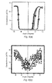
Figure 6(a) shows an experimental result of the electrical conductance between the electrodes as a function of the angle between the orientation of the external magnetic field and the electrodes, where said electrodes, comprising Nickel, are dived in a solution comprising Ni ions; -
Figure 6(b) shows an experimental result of the electrical conductance between the electrodes as a function of the angle between the orientation of the external magnetic field and the electrodes, where said electrodes, comprising Nickel, are dived in a solution having no Ni ions; -
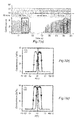
Figure 7(a) shows the result of an experiment with the device offigure 3 giving the evolution of conductance between the electrodes as a function of time, in the case where the external magnetic field magnitude varies over time; -
Figure 7(b) and 7(c) both show the evolution of the conductance offigure 7(a) as a function of the evolution of the magnitude of the external magnetic field; -
Figure 8 shows a single electrode which ferromagnetic material is covered by a layer of a non-ferromagnetic material; -
Figure 9(a) shows two electrodes disposed face to face, one of which comprising a cover layer of a non-ferromagnetic material andFigure 9(b) shows two electrodes disposed face to face both comprising such a cover layer. - A way to obtain the
cell 10 offigure 1(a) is described hereinafter. - An initial pair of electrodes separated by a few micrometers gap (for example a 5µm gap) is patterned over Si/SiO2 wafer 1 by standard optical UV lithography using reversible AZ5214 resist. A double layer of Ti(5nm)/Au(50nm) (Au = top part, Ti = bottom part improving the Au adhesion on the substrate) are then e-beam evaporated, followed by a lift-off in acetone, to obtain the metallic electrodes. The inter-electrode distance (gap) is then decreased down to a value, for example comprised between 1 nm to 100nm, by patterning two tips (ends of the electrodes) face to face using e-beam lithography. At this point, we obtain a sample having
metallic electrodes electrodes - Fabrication of the
PDMS structure 12 for the electrolyte/solution starts by creating an SU-8 master template defined by optical lithography, where a reversed image of the microfluidic channels is patterned in SU-8 spin coated onto a silicon wafer. A commercially available PDMS elastomer, Sylgard 184 from the company Dow Corning, may be used to be poured over the SU-8 master. The elastomer is mixed with a baking agent in 10 to 1 ratio and a vacuum pump dessicator is used to remove air bubbles from the mixture. The viscous PDMS solution is poured over the master and cured at 65°C for 1h, after which the replica is peeled away from the master. - Access to the
microfluidic circuitry 13 is obtained by using a biopsy punch to makeholes 14 in thePDMS 20. - To ensure sticking between the
PDMS 20 and the sample, oxygen plasma under RF power is used to activate surface chemical bonds in both the PDMS and the silicon. - Alignment of the
microfluidic inlet channels 14 with the patternedelectrodes channel 13 over theelectrodes 20, 21 (figure 1(b) ). - This is important to define, at the level of the gap between the
electrodes -
Plastic tubes 15 are introduced into theholes 14 of thePDMS 13, with eventually UV polymerizing glue to prevent any leaks. - The fabrication process of the
cell 10 is then terminated. - The
typical cell 10 built in this way is about 100 µm wide and 40 µm high (figure 1(a) ). - In
figures 1(a) and 1(b) , it should be noted that thehorizontal bar scale 11 corresponds to 200nm. The gap between theends electrodes figure 1(b) , we can also see acounter electrode 22 and areference electrode 23. The electrodes of interest (working electrodes) are theelectrodes figure 1(c) . Infigure 1(b) ,reference 30 corresponds to the electrolyte/solution. - Further information on the fabrication process of the cell may be obtained in " Heteronanojunctions with atomic size control using a lab-on-chip electrochemical approach with integrated microfluidics", Lunca Popa & al., Nanotechnology 22 (2011) 215302, pp 1-7.
- To finally obtain a
device 100 according to the invention, an external means for applying an external magnetic field (H0) trough the cell is installed. This field magnetizes theferromagnetic electrodes 20, 21 (with resulting magnetization M) and generate an induced magnetic field, B. The resulting created induction field B is written asB = µ 0(H +M ), where M is the local magnetization and H the local magnetic field. Inside a ferromagnetic materialB ≈ µ 0M , as its magnetization M dominates. Outside the magnetic material,M ≈ 0 andH =H 0 +HM involves the sum of the external magnetic fieldH 0 and the fieldHM generated by the magnetization of the electrodes, so thatB = µ0(H 0 +HM ). - The external magnetic field H0 can be generated with different means, well-known of the person skilled in the art.
- For the experiments shown here, we use an electromagnet 100' capable of creating a field of H0 = 1 T in a 8mm wide bore, that can be rotated in space. This is a so-called portable electromagnet, with a weight not exceeding a few tens of kilos, without necessary cooling fluids.
- This electromagnet 100' is illustrated in
figure 3 , together with thedevice 100 with theelectrodes figure 2 . The electromagnet 100' comprises twowindings device 100, with amagnetic core 103 and means 104 for rotating the windings together with themagnetic core 103 around the Y-direction. Said means 104 makes possible the change of direction of the external magnetic field H0 and hence the change of direction of the magnetization M of the electrodes. The magnitude of the external magnetic field H0 may be changed by varying the intensity I of the current circulating into thewindings - Instead of an electromagnet, a superconducting magnet may be used in the device of
figure 3 . - Mechanical rotation of said means for generating the external magnetic field H0 and/or of the device itself can achieve the same goals. For example, we may have, as well known from the person skilled in the art, a set of permanent magnets which can rotate around the
device 100 in order to change the magnitude of H0. Rotation of thedevice 100 with respect to the set of permanent magnets allows varying the orientation of the external magnetic field H0. In both cases, we may then change the orientation of the magnetization M in the electrodes. - Of course, in a more simple case where variation of the orientation of said magnetization is not necessary, a permanent magnet may be used in conjunction with ferromagnetic electrodes having remanence properties. In that case, the external permanent magnet initiates magnetization of the electrodes. Magnetization of the device can persist after reducing H0 down to zero.
- In
figure 1(c) , we can observe that the workingelectrodes 20, 21 (ferromagnetic) are arrow-shaped. It should be noted that other shapes ofelectrodes - An alternative embodiment for these electrodes is shown in
figure 2 . In that case, theends electrodes figure 2 are also those which are represented infigure 3 , together with theexternal means - It should be noted that, for the planar electrodes of
figure 2 , the fabrication process of the electrodes for reaching small gaps, typically between 1nm and 100nm, involve high-resolution electron beam lithography. Optical lithography combined with angle deposition methodologies as proposed in nanotrench for nano and micro particle electrical interconnects, J.F. Dayen & al., Nanotechnology, 21, 335303 (2010), can also be used as simpler alternatives. The fabrication of the remaining of thecell 10 is unchanged. - In addition, in the cell of
figure 1(a) , themicrofluidic circuitry 13 has a specific shape but other shapes may be provided. The important aspect is that acontainer 13 may be defined to dive theelectrodes electrodes ferromagnetic material solution 30. The inter-electrode distance DG equals the distance DF between the correspondingferromagnetic materials electrodes 20, 21 (seefigure 3 ). - By using the device of
figure 3 (with means for applying an external magnetic field H0) together with the working electrodes offigure 2 , a study of the chemical reaction CR (redox): - Ni2+ (paramagnetic species) + 2e- ↔ Ni (CR) has been carried out.
- It is reminded that paramagnetic ions with a concentration c (mol.m-1) in a solution and a molar magnetic susceptibility χm (m3.mol-1) experience a gradient force density F (N.m-3) which is of the form:

µ 0 = 4π.10-7 T.m.A-1
B, the magnetic field induced in theferromagnetic electrodes - F is often called "gradient force density" in the literature because it depends on the product between B and the gradient of B. Hereinafter, F is also named "gradient force", "force field", "force density" or "gradient field force".
-
Figure 4(a) shows the gradient force density resulting of a simulated application of an external magnetic field on the device offigure 3 . The external magnetic field has a constant magnitude of H0 = 0.8 Tesla and is applied in the longitudinal direction of the electrodes (direction X), namely perpendicularly to the planar ends 201, 211 of theelectrodes - The inter-electrode distance DG (direction X) is of DG = 16nm. The width W (direction Y) of the electrodes is of W = 30 nm and their height H (direction Z) is of H = 16 nm, and the electrodes have a length L (direction X) of L = 300 nm in the simulation. The shape of the electrodes is rounded, in order to avoid artificial divergence in the numerical calculations. For example, a width of W = 30 nm relates to a flat width of 20 nm, with rounded angles. This choice of set of values is restricted by the necessary meshing and is a compromise for limiting the calculation time.
- The concentration c of Ni ions is c = 1 M and the simulation is made at ambient temperature (T = 300K). It is reminded that, at the ambient temperature, the molar magnetic susceptibility of the paramagnetic Ni2+ ions is of about χm = 4.2*10-8 m3.mol-1. Given the concentration, it gives a product cχm = 4.2*10-5.
- The simulation is carried out with a well-defined computer code (Finite Element/Boundary Element micromagnetic code), see handbook of Magnetism and Advanced Magnetic Materials, edited by Helmut Kronmüller and Stuart Parkin, vol. 2: Micromagnetism, 2007, John Wiley & sons, Ltd; article "Guided Spin waves", in particular in its ).
- Given the orientation of the magnetic gradient force in
figure 4(a) , where the external field is along the electrodes axis directions, or the so-called longitudinal case; we note that a trap for the Ni2+ ions is provided between theends electrodes electrodes paramagnetic H 20- ions near the surface electrode (Pt) in article D2 or D3. - However, the maximum magnitude of the gradient force density is of the order of 109 N.m-3. This value is five orders higher than that one obtained in D3 (104 N.m-3). And even though a correction is made on the results of document D3 to take into account the differences in nature and concentration of the paramagnetic species between article D3 and the present simulation (cχm = 2 - 4.10-7 in article D3; cχm = 4.2*10-5 in the present simulation;), the gradient force density in D3 would be of the order of 106 N.m-3, namely 3 orders lower than the gradient force density obtained in the present simulation.
- As the external magnetic field is comparable in the present simulation (H0 = 0.8T) and article D3 (0.4 to 1T), it means that the
electrodes - According to the inventors, the high magnetic field gradient (dB/dz) is obtained due to the miniaturization of the
electrodes - With this code, parametric tests have been carried out.
- We found that increasing the length L of the electrodes has a negligible impact on the numerical outcome.
- We also found that increasing the height H of the electrodes (thickness) does not change the results either.
- Increasing the width W of the electrodes does not change significantly the maximum value of the force density (tested numerically up to 1 micron in the longitudinal case, but should mathematically remain valid up to infinite widths).
- For the longitudinal case calculation (H0 according to the X-direction;
Fig. 4(a) ), increasing the inter-electrode distance DG up to 1 micron does not diminish the forces estimates by more than one order of magnitude. - In practice, the important parameter is the inter-electrode distance DG, which may then be between 1nm and 1µm. Advantageously, said distance DG will be between 1nm and 500nm, between 1nm and 300nm or, preferably between 1nm and 100nm, this latter range being a range wherein the maximum value of the force field are similar to the results detailed above for the specific case DG = 16nm.
- Consequently, convection of Ni2+ towards the inter-electrode volume and their residency time are much more modified than in D3. The consequence is that the equilibrium constant K of the chemical reaction CR is changed significantly. The kinetics of the chemical reaction is therefore also changed significantly.
- A real control of the chemical reaction can then be achieved.
- Moreover, the inventors have noted that the control of the chemical reaction can be enhanced by controlling the orientation of the magnetic field induced in the ferromagnetic material.
- Indeed, thanks to the above-mentioned code, the inventors show that the control of the orientation of the external magnetic field H0 with respect to the
electrodes - A result of this study is shown in
figure 4(b) . - In
figure 4(b) , the conditions for the simulation are the same as forfigure 4(a) except that the external magnetic field is applied in the transverse direction (direction Y), namely in a parallel manner with respect to theends electrodes - In
figure 4(b) , similar values of the maximum magnetic field gradient (dB/dz) and the maximum magnitude of the gradient force density are obtained, compared to the simulation offigure 4(a) . - However, we note that in
figure 4(b) the orientation of the magnetic field brings about a repulsion of the Ni2+ ions away from the inter-electrode area (gap). - For the chemical reaction CR, it means that the passage of the electrons located in the gap towards the Ni electrode will be promoted. The equilibrium constant of the chemical reaction CR will then change significantly.
- This is counter-intuitive, as we expect that paramagnets should be attracted by ferromagnetic elements. This unexpected finding has never been reported in the literature. Furthermore, we found that the magnitude of the repulsive force is remarkably large, reaching the same order of magnitude as the attractive force field of
Fig 4(a) . - For the transverse case calculation (H0 according to the Y-direction;
Fig. 4(b) ), when we vary the distance DG between the electrodes, we found that the maximum repulsive force field value remains of the same order of magnitude, but the volume where this force field is reached does not increase much with this distance DG, and is in the middle between the electrodes. This means that the volume fraction of the gap where the force field is largest decreases with increasing distance between electrodes, but that there is still in the environment of the mid-distance area between the electrodes a high value of the repulsive force field. - It should be noted that the transverse can also be along the Z-direction as, in a first approximation, there is no difference between Z and Y.
- From the results of
figures 4(a) and 4(b) , we finally note that the equilibrium constant K of the chemical reaction CR can be changed significantly, promoting either one side or the other of a chemical equilibrium reaction (figure 4(b) ) or not (figure 4(a) ). - This has interesting applications of the charge transfer properties of the two chemical by products related to the two sides of this chemical reaction are very different. In other words, one can reach the extreme case where one side relates to ions in solution (Ni2+), and the other to a metal (Ni) separating the two electrodes.
- The control of the orientation of the external magnetic field gives rise to remarkable electronic properties.
- Indeed, when the forces exerted on the paramagnetic species are repulsive (
figure 4(b) ), electrons pass in a metallic bridge created between theelectrodes figure 4(a) ), the metallic bridge is dissolved, opening the circuit (OFF state; high-resistance interconnection). - A switch function can then be created between the
electrodes figures 5(b) (ON state) and 5(a) (OFF state). - Measurements on an experiment set-up were made with the device of
figure 3 to confirm that a switch function was effectively obtained, in the conditions in which the simulations were made. - The results are given in
figure 6(a) . - To make a valuable comparison, measurements were also made without Ni2+ in solution, which results are given in
figure 6(b) . This unambiguously shows that paramagnetic ions in solution are responsible, and necessary, for the magnetic-induced change of conduction. -
Figures 6(a) and 6(b) provide the conductance of theelectrodes - In
figure 6(a) , namely in presence of Ni ions in the solution, a great change in conductance is observed between the angle zero and the angle ± 90°. Where the angle is close to zero, the conductance is close to zero and corresponds to a resistance ROFF > 100kΩ (OFF state;figure 5(a); figure 4(a) , attraction of the Ni ions). Where the angle is close to ±90°, the conductance is quite high and corresponds to a resistance RON = 100 Ω (ON state;figure 5(b); figure 4(b) , repulsion of the Ni ions). - Now, if we pay attention to the results provided in
figure 6(a) , namely in the absence of Ni ions in solution, the variation of the conductance is negligible between the angle zero and the angle + 90° (or between the angle zero and the angle -90°). - The comparison between both figures clearly shows that it is the specific orientation of the external magnetic field H0 with respect to the
electrodes - Moreover, in both cases, the magnitude of the external magnetic field (constant) can be set to other values than H0 = 0.8T in order to manage the magnetic field gradient force between the electrodes, namely the level of attraction/repulsion of the paramagnetic species.
- As it is the case for the results described here above, we may dispose magnets capable of creating an external magnetic field H0 which orientation changes from the X-direction to the Y-direction, and conversely in order to manage the orientation of the induced magnetic field B with respect to the
electrodes device 100. The force field behaviour in the Z-direction is similar to the one in the Y-direction, so we can generalize as an orientation change between longitudinal (X) and transverse (in the YZ plane) directions. - The induced magnetic field B near the ferromagnetic electrodes may be changed otherwise.
- Indeed, in that aim, we may apply an external magnetic field for example in the Y-direction which magnitude is varying over time. Due to the magnetic properties of the electrodes, the induced magnetization of the
ferromagnetic electrodes -
Figure 7(a) shows, in the upper part, the evolution of the magnitude of the external magnetic field (H0 = ± 0.8T) as a function of time, in the middle part, the presence/absence of Ni ions in the solution and, in the lower part, the conductance obtained between the ferromagnetic electrodes in response to the evolution of the magnitude of said external magnetic field H. - Between t= 0s and 90s, Ni ions are present in the solution. The magnitude of the external magnetic field H0 is changed over time at a first rate. We can see that the conductance changes with the evolution of the magnitude of the external magnetic field. The periodic evolution of said magnitude between its extreme values (+0.8T; -0.8T) results in the successive activation of the ON state (close to the extreme values of H0) and of the OFF state (when H0 has intermediate small values between the extreme values; especially when H0 is close to zero) of the switch. Moreover, the activation frequency of the switch is twice as the frequency variation of the magnitude of the external magnetic field.
- Between t = 90s and 700s, there is no Ni ions in the solution. The magnitude of the external magnetic field H0 is changed over time from a first rate to a second rate, which is higher than the first rate. In that case, no evolution of the conductance is observed, whatever the rate of the magnitude change. Eliminating Ni ions in the solution results in an open contact (OFF state). These results are similar to those observed in
figure 6(b) . - Beyond t = 700s, Ni ions are present in the solution. The magnitude of the external magnetic field H is changed over time at the second rate. We also observe that conductance changes over time, additionally still at a frequency which is twice as important as the evolution of said magnitude.
-
Figures 7(b) and 7(c) relates to magnetoresistance curves which correspond totime zones figure 7(a) . To obtain these figures, time is eliminated from the results showed infigure 7(a) , one therefore obtain the evolution of the sample resistance (or conductance) with the magnitude of an external applied field H0. These figures show that very large resistance changes under variable applied magnetic field are obtained and that these properties are recovered (zone 2) when reinstating the initial (zone 1) electrochemical environment (presence of Ni ions). - It is reminded that the electric switch controlled by an external magnetic field is the basic element of a spin valve. And this basic element has ON/OFF ratio ROFF/RON ≥ 1000, which is much higher than the currently used solid-states devices used as basic elements for spin valves, which generally provide an ON/OFF ratio strictly lower than 2.
- Having a means for applying an external magnetic field which magnitude is either constant (with a constant orientation or not) or variable with time is not compulsory.
- Indeed, for some electrodes having strong ferromagnetic properties, it is possible to magnetize them and to take advantage of the remanence properties of these electrodes. In that case, we may imprint, prior to chemical processing, the stability of the chemical reaction (equilibrium constant). For example, we may obtain an induced magnetic field B very near the electrodes of amplitude in the range 0.1 T to 2.5 T, depending on the magnetic material used for the electrodes.
- The chemical reaction CR can be extended to any chemical reaction of the redox type:
- Mn+ (paramagnetic species) + ne- ↔ M
- However, this value may be higher.
- For example for an iron-based electrode, Ms reaches 2.4 T.
- In addition, it should be noted that the magnetic field B (and its derivative dB/dz) increase the magnetization of the electrodes. Indeed, both are proportional to M inside the magnetic electrodes, and approximately proportional outside, as the magnetic field created by the magnetic electrodes is proportional to M. The gradient force value will therefore scale with (Ms)2, If we replace Ni by Fe, with an increase of a factor 4 of the magnetization value, an average increase of a
factor 10 to 16 will be found for the magnitude of the gradient force. - The consequence is that, for the same conditions, higher force field gradients may be obtained. A similar result is obtained with cobalt-based electrodes. Indeed, Fe and Co have stronger ferromagnetic properties than Ni.
- From the magnitude of our observations on the redox reaction of Ni2+ ions, the opening and closure of the bridge can alternatively be obtained if we modify the applied voltage on the two electrodes (versus a reference electrode in the circuit), by more than 100 mV. This provides an estimate to the contribution of the Gibbs free energy of 0.1 eV per molecule. This indicates that the invention is not limited to chemical reactions of the redox type.
- Indeed, the invention may be extended to chemical reactions that involve building supramolecular architectures (supramolecular architectures may be defined as an ensemble of molecules linked by weak interactions, typically of the order of 0.01eV to 0.2eV per molecule), where the equilibrium conditions can be significantly altered by energy contributions of the order of kBT (thermal energy; 0.03ev at room temperature). In that case, the paramagnetic species are the molecules of the assembly. If chemical bounds involve paramagnetic species, as radicals, ions or radical ions, the variation in energy related to the magnetic field force gradient acting on the molecules might stabilize or destabilize the supramolecular architecture It is important because supramolecular molecules prevail in life science.
- The invention may also be extended to other chemical reactions in which a radical intervenes, such as radical polymerization where a chemical reaction initiated by a radical monomer controls the characteristics of the polymeric chain. The radical plays then the role of the paramagnetic species.
- As mentioned previously, other shapes for the
electrodes figures 1(c) . For arrow shaped-electrodes, one expect to enhance further the gradient force, following simple macroscopic arguments that a conical-type shape increase the magnetic field density (especially at the level of itsends figure 1(c) ), and therefore the induction field B and its gradient (dB/dz) created by the magnetization (M) of the electrodes. - According to the type of chemical reactions concerned, high magnetization magnetic materials such as Fe or Co alloys, or even rare earth materials (ex.: Gd, Eu, Sm) or their alloys may be used, which can potentially increase the value of the saturation magnetization (Ms) by a factor up to five.
- It should be noted that the
device 100 according to the invention works in solution and can therefore be used for bio-applications, especially if the ferromagnetic materials of the electrodes are covered by a non-ferromagnetic biocompatible material (ex.: a metal) with a small thickness, typically a few nanometres (nm) and not exceeding 40 nm. - Indeed, it should be noted that very large gradient field forces can occur in the vicinity of a single electrode. As a simple rule of thumb, the estimated attractive or repulsive forces are diminished by a factor two when the second electrode is positioned infinitely far from the first one. If we use a criterion of magnetic force field one order of magnitude larger than those reported in document D3 (namely a value of 107 N.m-3 for the present invention; as for D3 it would be of the order of 106 N.m-3 for a similar value of the product cχm), we estimate from our calculations that this force field exists within a distance of the order of 40 nm from the edge of an electrode. A distance reduced to 20 nm results in a force field one order of magnitude larger (namely 108 N.m-3 for the present invention).
- When a non-ferromagnetic cover layer, for example a biocompatible metal layer, is added on the surface of the electrodes, it is therefore essential to reduce its thickness below 40 nm. Accordingly, the thickness of the non-ferromagnetic cover layer should lie in the range 1nm to 40nm or, advantageously, 1 nm to 20nm.This fact was not considered previously in the literature, where the smallest values of thickness of non-ferromagnetic protecting layers reported are between 50nm and 200 nm. For instance, in document D3, the electrode is covered by a Pt layer (non-ferromagnetic) which thickness is of 50 nm.
- For illustration purposes,
figure 8 shows asingle electrode 20 with itsferromagnetic material 200 covered by alayer 220 made of a non-ferromagnetic material, for example biocompatible. We can see that theferromagnetic material 200 cannot be in contact with thesolution 30, thecover layer 220 separating theferromagnetic material 200 from thesolution 30 in which theelectrode 20 is dived. - Of course, the device with a single electrode also works in the absence of non-ferromagnetic cover layer.
- As already mentioned previously, , when two
electrodes ferromagnetic material electrode figure 3 ). The inter-electrode distance DG is then the distance DF between theferromagnetic materials - However, we may have one 21 of them which is free of such a cover layer while the other 20 comprises such a
cover layer 220 with a thickness less than 40nm (seefigure 9(a) ). - We may also provide a
cover layer electrodes 20, 21 (seefigure 9(b) ). - In those cases, the relevant distance which has to be taken into account is the distance DF between the ends of the
ferromagnetic materials electrodes - Where, both
electrodes cover layer
the local magnetic induction field B is of the order of the saturation magnetization (Ms). For a Ni electrode, Ms = 0.62T.
Claims (15)
- A device (100) for controlling a chemical reaction, said device having:- a container (13) comprising a solution (30) including at least one paramagnetic species;- at least one electrode (20, 21) comprising at least one ferromagnetic material (200, 210), said at least one electrode being dived in said solution;- a means for applying an external magnetic field (H0) so as to magnetize said electrode (20, 21), the combination of the external magnetic field (H0) and the magnetization (M) of said electrode creating a magnetic induction field (B) in the electrodes (20, 21) and the container (13);characterized in that said at least one electrode (20, 21) has either no cover layer of a non-ferromagnetic material on said at least one ferromagnetic material or comprises a cover layer of a non-ferromagnetic material separating said at least one ferromagnetic material from the solution (30), the thickness of the cover layer being less than 40nm.
- A device (100) according to claim 1, comprising at least two electrodes (20, 21) each comprising at least one ferromagnetic material, said electrodes being dived in said solution (30), where:- both electrodes (20, 21) have no cover layer of a non-ferromagnetic material on the corresponding said at least one ferromagnetic material; or- both electrodes (20; 21) have a cover layer (220, 221) of a non-ferromagnetic material separating the corresponding said at least one ferromagnetic material (200, 210) from the solution (30), the thickness of each cover layer (220, 221) being less than 40nm; or- one and only one (20) of the two electrodes (20, 21) has a cover layer (220) of a non-ferromagnetic material separating said at least one ferromagnetic material (200, 210) from the solution (30), the thickness of the cover layer (220) being less than 40nm;
the ends (201, 211) of said electrodes (20, 21) being further disposed face to face, so that the distance (DF) between the corresponding ferromagnetic materials (200, 210) of the electrodes is comprised between 1 nm and 1 µm. - A device (100) according to the preceding claim, wherein the distance (DF) between the corresponding ferromagnetic materials (200, 210) of the electrodes (20, 21) is comprised between 1nm and 100nm.
- A device according to one of the preceding claims, wherein said means (101, 102) for applying the external magnetic field (H0) are adapted for changing the orientation of the magnetization (M) in said at least one electrode.
- A device (100) according to the preceding claims, wherein said means (101, 102) for applying an external magnetic field (H0) are adapted for varying the magnitude of said external magnetic field (H0), in order to change the orientation of the magnetization (M) in said at least one electrode.
- A device (100) according to one of the claims 3 or 4, wherein said means (101, 102) for applying an external magnetic field (H0) are adapted for changing the direction of said external magnetic field (H0), in order to change the orientation of the magnetization (M) in said at least one electrode.
- A device (100) according to one the preceding claims, wherein, when a cover layer of a non-ferromagnetic material separating said at least one ferromagnetic material of the or each electrode (20, 21) from the solution (30) is provided, the thickness of said cover layer is than 20nm.
- A device (100) according to one of the preceding claims, wherein the end (201, 211) of said at least one electrode (20, 21) is planar or arrow-shaped.
- A device (100) according to one of the preceding claims, wherein said means (101, 102) for applying the external magnetic field (H0) is an electromagnet, a superconducting magnet or at least one permanent magnet.
- A device (100) according to the preceding claim, wherein, the ferromagnetic material of said at least one electrode (20, 21) has remanence properties.
- A device (100) according to one of the preceding claim, wherein the external magnetic field (H0) does not exceed 5T.
- A device (100) according to one of the preceding claims, wherein the ferromagnetic material is a metal, a metal alloy or a rare earth material such as Gd, Eu or Sm.
- Use of a device according to one of the claims 1 to 12 in order to control the equilibrium constant of a chemical reaction and/or the kinetics of said chemical reaction.
- Use of a device according to one of the claims 2 to 12 as an electrical switch, providing an ON/OFF ratio ROFF/RON greater than 2, for example greater than 10; where ROFF is the interconnection resistance between the electrodes in the OFF position of the switch and RON is the interconnection resistance between the electrodes in the ON position of the switch.
- Use according to the preceding claim, wherein the ON/OFF ratio is greater than 100, for example greater than 1000.
Priority Applications (1)
| Application Number | Priority Date | Filing Date | Title |
|---|---|---|---|
| EP20130306516 EP2868373A1 (en) | 2013-11-05 | 2013-11-05 | A device for controlling a chemical reaction by a magnetic field and use of said device. |
Applications Claiming Priority (1)
| Application Number | Priority Date | Filing Date | Title |
|---|---|---|---|
| EP20130306516 EP2868373A1 (en) | 2013-11-05 | 2013-11-05 | A device for controlling a chemical reaction by a magnetic field and use of said device. |
Publications (1)
| Publication Number | Publication Date |
|---|---|
| EP2868373A1 true EP2868373A1 (en) | 2015-05-06 |
Family
ID=50150527
Family Applications (1)
| Application Number | Title | Priority Date | Filing Date |
|---|---|---|---|
| EP20130306516 Withdrawn EP2868373A1 (en) | 2013-11-05 | 2013-11-05 | A device for controlling a chemical reaction by a magnetic field and use of said device. |
Country Status (1)
| Country | Link |
|---|---|
| EP (1) | EP2868373A1 (en) |
Citations (3)
| Publication number | Priority date | Publication date | Assignee | Title |
|---|---|---|---|---|
| US3409471A (en) * | 1963-06-19 | 1968-11-05 | Siemens Ag | Method of producing electrical energy using magnetic field |
| FR2845298A1 (en) * | 2002-10-08 | 2004-04-09 | Commissariat Energie Atomique | DEVICE FOR MIXING FLUIDS |
| US20110027623A1 (en) * | 2009-01-21 | 2011-02-03 | John Michael David Coey | Electrochemical device |
-
2013
- 2013-11-05 EP EP20130306516 patent/EP2868373A1/en not_active Withdrawn
Patent Citations (3)
| Publication number | Priority date | Publication date | Assignee | Title |
|---|---|---|---|---|
| US3409471A (en) * | 1963-06-19 | 1968-11-05 | Siemens Ag | Method of producing electrical energy using magnetic field |
| FR2845298A1 (en) * | 2002-10-08 | 2004-04-09 | Commissariat Energie Atomique | DEVICE FOR MIXING FLUIDS |
| US20110027623A1 (en) * | 2009-01-21 | 2011-02-03 | John Michael David Coey | Electrochemical device |
Non-Patent Citations (3)
| Title |
|---|
| N. B. CHAURE ET AL: "Enhanced Oxygen Reduction at Composite Electrodes Producing a Large Magnetic Gradient", JOURNAL OF THE ELECTROCHEMICAL SOCIETY, vol. 156, no. 3, 8 January 2009 (2009-01-08), pages F39 - F46, XP055120662, ISSN: 0013-4651, DOI: 10.1149/1.3000576 * |
| PEROV N S ET AL: "An electro-chemical magnetic field sensor", SENSORS AND ACTUATORS A, ELSEVIER SEQUOIA S.A., LAUSANNE, CH, vol. 81, no. 1-3, 1 April 2000 (2000-04-01), pages 351 - 354, XP004191323, ISSN: 0924-4247, DOI: 10.1016/S0924-4247(99)00109-0 * |
| RESSIER ET AL: "Fabrication of planar cobalt electrodes separated by a sub-10nm gap using high resolution electron beam lithography with negative PMMA", ULTRAMICROSCOPY, ELSEVIER, AMSTERDAM, NL, vol. 107, no. 10-11, 27 July 2007 (2007-07-27), pages 985 - 988, XP022174234, ISSN: 0304-3991, DOI: 10.1016/J.ULTRAMIC.2007.04.013 * |
Similar Documents
| Publication | Publication Date | Title |
|---|---|---|
| Schloerb et al. | Magnetic nanowires by electrodeposition within templates | |
| Smistrup et al. | Magnetic separation in microfluidic systems using microfabricated electromagnets—experiments and simulations | |
| Niarchos | Magnetic MEMS: key issues and some applications | |
| Zehner et al. | Nonvolatile electric control of exchange bias by a redox transformation of the ferromagnetic layer | |
| Butcher et al. | Magnetic forces in paramagnetic fluids | |
| Le Roy et al. | Fabrication and characterization of polymer membranes with integrated arrays of high performance micro-magnets | |
| Holzinger et al. | Directed magnetic particle transport above artificial magnetic domains due to dynamic magnetic potential energy landscape transformation | |
| Frolov et al. | Structural and magnetic properties of Ni-Fe nanowires in the pores of polymer track membranes | |
| Zanini et al. | Micromagnet structures for magnetic positioning and alignment | |
| Perzanowski et al. | Exchange bias in the [CoO/Co/Pd] 10 antidot large area arrays | |
| Białostocka et al. | The effect of a substrate material on composition gradients of Fe-Ni films obtained by electrodeposition | |
| Aziz et al. | Angular dependence of domain wall resistivity in artificial magnetic domain structures | |
| Nichterwitz et al. | Voltage-controlled ON switching and manipulation of magnetization via the redox transformation of β-FeOOH nanoplatelets | |
| Peipmann et al. | Electrocodeposition of nickel–alumina nanocomposite films under the influence of static magnetic fields | |
| Silverio et al. | On-chip magnetic nanoparticle manipulation and trapping for biomedical applications | |
| Santhi et al. | Dendritic Ag–Fe nanocrystalline alloy synthesized by pulsed electrodeposition and its characterization | |
| Moritz et al. | Magnetophoresis-assisted capillary assembly: A versatile approach for fabricating tailored 3D magnetic supercrystals | |
| Volkov et al. | Domain-wall damping in ultrathin nanostripes with Dzyaloshinskii-Moriya interaction | |
| EP2868373A1 (en) | A device for controlling a chemical reaction by a magnetic field and use of said device. | |
| Ouk et al. | Superparamagnetic microbead transport induced by a magnetic field on large-area magnetic antidot arrays | |
| Tikhonov et al. | Magnetization of permalloy films | |
| Golvano-Escobal et al. | Spontaneous formation of spiral-like patterns with distinct periodic physical properties by confined electrodeposition of Co-In disks | |
| Coey | Magnetoelectrochemistry | |
| Saadinia et al. | Fabrication and magnetic properties of pulse electrodeposited FeSn nanowire arrays | |
| Li et al. | Tailoring the morphology, structure and magnetic properties of electrodeposited CoFe films onto Si (100) by in-situ uniform and gradient high magnetic fields |
Legal Events
| Date | Code | Title | Description |
|---|---|---|---|
| PUAI | Public reference made under article 153(3) epc to a published international application that has entered the european phase |
Free format text: ORIGINAL CODE: 0009012 |
|
| 17P | Request for examination filed |
Effective date: 20131105 |
|
| AK | Designated contracting states |
Kind code of ref document: A1 Designated state(s): AL AT BE BG CH CY CZ DE DK EE ES FI FR GB GR HR HU IE IS IT LI LT LU LV MC MK MT NL NO PL PT RO RS SE SI SK SM TR |
|
| AX | Request for extension of the european patent |
Extension state: BA ME |
|
| STAA | Information on the status of an ep patent application or granted ep patent |
Free format text: STATUS: THE APPLICATION IS DEEMED TO BE WITHDRAWN |
|
| 18D | Application deemed to be withdrawn |
Effective date: 20151107 |