EP2868363A1 - System and method for treating a gas stream - Google Patents
System and method for treating a gas stream Download PDFInfo
- Publication number
- EP2868363A1 EP2868363A1 EP20130190613 EP13190613A EP2868363A1 EP 2868363 A1 EP2868363 A1 EP 2868363A1 EP 20130190613 EP20130190613 EP 20130190613 EP 13190613 A EP13190613 A EP 13190613A EP 2868363 A1 EP2868363 A1 EP 2868363A1
- Authority
- EP
- European Patent Office
- Prior art keywords
- gas stream
- unit
- removal
- dryer
- dryer unit
- Prior art date
- Legal status (The legal status is an assumption and is not a legal conclusion. Google has not performed a legal analysis and makes no representation as to the accuracy of the status listed.)
- Withdrawn
Links
Images

Classifications
-
- B—PERFORMING OPERATIONS; TRANSPORTING
- B01—PHYSICAL OR CHEMICAL PROCESSES OR APPARATUS IN GENERAL
- B01D—SEPARATION
- B01D53/00—Separation of gases or vapours; Recovering vapours of volatile solvents from gases; Chemical or biological purification of waste gases, e.g. engine exhaust gases, smoke, fumes, flue gases, aerosols
- B01D53/26—Drying gases or vapours
- B01D53/261—Drying gases or vapours by adsorption
-
- B—PERFORMING OPERATIONS; TRANSPORTING
- B01—PHYSICAL OR CHEMICAL PROCESSES OR APPARATUS IN GENERAL
- B01D—SEPARATION
- B01D53/00—Separation of gases or vapours; Recovering vapours of volatile solvents from gases; Chemical or biological purification of waste gases, e.g. engine exhaust gases, smoke, fumes, flue gases, aerosols
- B01D53/002—Separation of gases or vapours; Recovering vapours of volatile solvents from gases; Chemical or biological purification of waste gases, e.g. engine exhaust gases, smoke, fumes, flue gases, aerosols by condensation
-
- B—PERFORMING OPERATIONS; TRANSPORTING
- B01—PHYSICAL OR CHEMICAL PROCESSES OR APPARATUS IN GENERAL
- B01D—SEPARATION
- B01D2253/00—Adsorbents used in seperation treatment of gases and vapours
- B01D2253/10—Inorganic adsorbents
- B01D2253/106—Silica or silicates
-
- B—PERFORMING OPERATIONS; TRANSPORTING
- B01—PHYSICAL OR CHEMICAL PROCESSES OR APPARATUS IN GENERAL
- B01D—SEPARATION
- B01D2257/00—Components to be removed
- B01D2257/40—Nitrogen compounds
- B01D2257/404—Nitrogen oxides other than dinitrogen oxide
-
- B—PERFORMING OPERATIONS; TRANSPORTING
- B01—PHYSICAL OR CHEMICAL PROCESSES OR APPARATUS IN GENERAL
- B01D—SEPARATION
- B01D2257/00—Components to be removed
- B01D2257/50—Carbon oxides
- B01D2257/504—Carbon dioxide
-
- B—PERFORMING OPERATIONS; TRANSPORTING
- B01—PHYSICAL OR CHEMICAL PROCESSES OR APPARATUS IN GENERAL
- B01D—SEPARATION
- B01D2258/00—Sources of waste gases
- B01D2258/02—Other waste gases
- B01D2258/0283—Flue gases
Definitions
- the present disclosure relates to a system and a method for treatment of a gas stream.
- the gas stream contains CO 2 , for example in an amount higher than 70%.
- the gas stream can be generated during the combustion of a fuel in a boiler or furnace for power plant production or for other industrial use or can derive from an industrial process.
- the combustion can be oxy-fuel combustion, i.e. combustion between a fuel and substantially pure oxygen or oxygen enriched air.
- the system and method aim at obtaining a substantially pure CO 2 stream.
- AU 2008 277 536 discloses a system and method for treating a gas stream containing CO 2 and other components, such as NO x .
- the gas stream is compressed in a plurality of stages, then the compressed gas stream is dehydrated and it is then cooled to condense CO 2 .
- AU 2008 277 536 suggests to remove water in two steps, namely a first step using means resistant to NO x and able to remove in addition to water also NO x , and a second step using a molecular sieve that is able to remove water with very high efficiency.
- the gas stream deprived of water is sent to a condenser, where CO 2 is liquefied.
- the inventors have found a way to further improve this process.
- An aspect of the disclosure includes providing a system and a method that are more reliable than those provided in the prior art.
- the system and method allow dehydration by adsorption by using a molecular sieve with a reduced risk that NO x can impair the molecular sieve.
- this shows a system 1 for treating a gas stream containing at least CO 2 , O 2 , water and NO x .
- the system 1 comprises a compressor 2, which can include one or more compressor stages that can be intercooled or not. Downstream of the compressor 2 a cooler 3 is provided (but it is not mandatory) and thus a first dryer unit 7 is provided downstream of the compressor 2; the first dryer unit 7 is a NO x tolerant dryer unit, i.e. a dryer unit that is not or it is affected to a limited extent by the presence of NO x in the gas stream; such a NO x tolerant dryer unit can for example be a silica gel dryer.
- a unit 9 for removal of NO x or NO x and CO 2 is provided downstream of the first dryer unit 7.
- the unit 9 for removal of NO x or NO x and CO 2 can be of different types, for example it can comprise one or more condensers preferably associated to one or more separators; in this case the condensers can be alternated to the separators (i.e. there are provided one condenser, then one separator, then another condenser, then another separator, and so on) or there can be a plurality of condensers and then a plurality of separators, or a combination of these configurations).
- the unit 9 for removal of NO x or NO x and CO 2 can comprise one or more distillation columns, or also other different devices, such as membrane separators and so on.
- the unit 9 for removal of NO x or NO x and CO 2 can also include different arrangements of condensers and/or separators and/or distillation columns and/o membrane separators etc.
- a second dryer unit 15 Downstream of the unit 9 for removal of NO x or NO x and CO 2 a second dryer unit 15 is provided and, in addition, a unit for final CO 2 removal 17 is provided downstream the second dryer unit 15.
- the second dryer unit 15 is a high efficiency dryer unit, i.e. a dryer unit that is able to remove a very high percentage of the water contained in the gas stream treated.
- second dryer unit 15 is a molecular sieve dryer.
- the unit for final CO 2 removal 17 can be of the same type as or it can be different from the unit 9 for removal of NO x or NO x and CO 2 .
- the unit for final CO 2 removal 17 can comprise one or more condensers preferably associated to one or more separators; in this case the condensers can be alternated to the separators (i.e. there are provided one condenser, then one separator, then another condenser, then another separator, and so on) or there can be a plurality of condensers and then a plurality of separators, or a combination of these configurations).
- the unit for final CO 2 removal 17 can comprise one or more distillation columns, or also other different devices, such as membrane separators, and so on.
- unit for final CO 2 removal 17 can also include different arrangements of condensers and/or separators and/or distillation columns and/o membrane separators etc...
- NO x includes mainly NO and NO 2 (other components defining NO x can be HNO 3 , N 2 O 4 , etc. but they are usually contained in a very low amount); NO is converted into NO 2 according to the main reaction NO + 1 ⁇ 2 O 2 ⁇ NO 2 .
- the gas stream is dried at the dryer unit 7; here the NO x is not troubling, because the dryer unit is NO x tolerant. Then NO x or NO x and CO 2 are removed from the gas stream at the unit 9; the gas stream is thus forwarded to the dryer unit 15.
- the residual NO x (in particular NO 2 ) in the stream gas downstream of the unit 9 for removal of NO x or NO x and CO 2 is low, such that it does not substantially impair the dryer unit 15.
- the dryer unit 15 can thus be selected according to the desired water removal, with limited risks that NO x in the gas stream can damage it.
- the gas stream depleted from water and NO x is thus supplied to the unit 17 where CO 2 is removed with high efficiency, without the risk or with a limited risk that water contained in the the gas stream can damage it or affect the process.
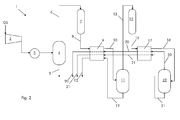
- Figure 2 shows in greater detail an example of a system similar to the system of figure 1 .
- the gas stream GS contains CO 2 (for example the amount of CO 2 is higher than 70% by volume of the gas stream GS).
- the gas stream also includes O 2 , water and NO x .
- Other components such as Argon or N 2 or other components can be contained in the gas stream GS.
- the system 1 comprises a compressor 2 defined by a compressor like for example a multi stage compressor; the multi stage compressor can also be an intercooled compressor.
- a cooler 3 Downstream the compressor 2, a cooler 3 to remove the heat gained by the gas stream GS during compression can be provided.
- NO x will tend to form acid.
- NO x includes mainly NO and NO 2 that react according to the reaction NO + 1 ⁇ 2 O 2 ⁇ NO 2 .
- a separator 4 is usually provided (but it is not mandatory) downstream of the compressor 2 (typically downstream of the cooler 3 when this is provided). From the separator 4 a liquid acid stream 5 containing the nitric acid and a compressed gas stream 6 are discharged.
- a first dryer unit 7 is provided downstream of the compressor 2.
- the dryer unit 7 is supplied with the compressed gas 6.
- the dryer unit 7 can be of different types (e.g. absorption, adsorption type); advantageously it is of the type tolerant to NO x , such that it is able to remove water and/or NO x but it is impaired by the residual NO x contained in the compressed stream 6 only to a limited extent (namely the NO 2 is directly troubling for the dryer unit and NO is only indirectly troubling according to the reaction NO + 1 ⁇ 2 O 2 ⁇ NO 2 ).
- the dryer unit 7 is a silica gel dryer.
- a gas stream 8 treated in the dryer unit 7 is supplied to the first unit 9 for removal of NO x or NO x and CO 2 that can for example comprise a first condenser, as explained above other examples of a unit for removal of NO x or NO x and CO 2 are possible.
- the first condenser 9 is provided downstream the dryer unit 7. At the first condenser 9 the stream 8 is cooled to cause condensation of NO 2 .
- the gas stream 8 contains NO x (i.e. NO and NO 2 ); at the conditions of the first condenser 9, NO 2 condenses whereas NO typically does not condense.
- NO 2 is removed from the gas stream by condensation and in view of the chemical reaction NO + 1 ⁇ 2 O 2 ⁇ NO 2 , NO is converted into NO 2 that in turn condenses; therefore as a whole the process causes NO x removal from the gas stream 8.
- the first condenser 9 also CO 2 condenses. Preferably most of the CO 2 condenses at the first condenser 9.
- the first condenser 9 discharges a stream 10.
- a separator 11 is provided downstream of the first condenser 9 (but the separator 11 is not mandatory).
- the separator 11 is supplied with the stream 10 and it is used for removing condensed NO 2 and CO 2 from the stream 10.
- the liquid stream 12 containing condensed NO 2 and CO 2 and a stream 13 (this is a gas stream) are discharged.
- the liquid stream 12 is passed through the first condenser 9 for cooling the stream 8 and is then stored or used in any other way.
- a second dryer unit 15 is provided downstream of the first condenser 9; preferably the second dryer unit 15 is provided downstream of the separator 11 when this is present.
- the second dryer unit 15 is supplied with the stream 13 to eliminate the remaining water that was not removed at the first dryer 7 or in separator 11.
- the second dryer unit 15 removes water with efficiency higher than the first dryer unit 7, i.e. the second dryer unit 15 is able to remove a very high percentage of the water contained in the gas stream treated in it.
- the second dryer unit 15 is preferably also able to remove water reaching a lower water content in the gas stream discharged therefrom than the first dryer unit 7.
- the second dryer unit 15 is preferably an adsorption dryer; for example the adsorption dryer defining the second dryer unit 15 comprises a molecular sieve dryer.
- the second dryer unit 15 discharges a stream 16 (this is a gas stream).
- the unit for final CO 2 removal 17 Downstream the second dryer unit 15 the unit for final CO 2 removal 17 is provided; the unit for final CO 2 removal 17 comprises for example second condenser 17 but, as explained above, other example for the unit for final CO 2 removal 17 are possible.
- the second condenser 17 is fed with the stream 16 and is used to condense CO 2 .
- the second condenser 17 discharges a stream 18.
- another separator 19 Downstream of the second condenser 17 another separator 19 is preferably provided (but it is not mandatory); the separator 19 separates off-gas (such as for example Argon, N 2 , CO 2 ) contained in the stream 18 from the liquid CO 2 .
- off-gas such as for example Argon, N 2 , CO 2
- the off-gas is passed through the second condenser 17 and first condenser 9 via line 20 to cool the streams 16 and 8 and is then discharged or vented to the atmosphere. This improves the thermal efficiency.
- the liquid CO 2 is also passed through the second condenser 17 and first condenser 9 via line 21 to cool the streams 16 and 8 and is then stored or used in any other way.
- the gas stream 8 is cooled to a first temperature and at the second condenser 17 the gas stream 16 is cooled to a second temperature.
- the second temperature is lower than the first temperature.
- the first temperature allows NO 2 condensation and CO 2 condensation at the first condenser 9 without risk of ice formation
- the second temperature allows CO 2 condensation (liquefaction) at the second condenser 17.
- the first temperature is between -15 and -35 °C and the final temperature is lower than -35 °C and preferably between -45 and -55 °C.
- CO 2 condensation (after the condensation at the first condenser 9 and second condenser 17) typically removes at least 90% of the CO 2 contained in the inlet gas GS.
- the compressor 2 is supplied with the gas stream GS deriving for example from the combustion of fuel in a boiler or from an industrial process.
- the stream GS contains CO 2 and in addition also at least O 2 , water and NO x . Moreover additional components can be included in the gas stream GS such as Argon, N 2 , etc.
- the gas stream GS is compressed up to 2-50 bar at the compressor 2 and it is then cooled at the cooler 3. During compression NO is converted into NO 2 and NO 2 reacts with water in the gas stream GS forming liquid nitric acid.
- the compressed stream is thus supplied to the separator 4, where the liquid acid stream 5 containing the nitric acid is removed. At the separator 4 up to 30-60% of the NO x contained in the gas GS is removed (according to the operating conditions, such as pressure).
- the gas stream 6 is discharged from the separator 4 and is supplied to the first dryer unit 7.
- the stream 8 discharged from the first dryer unit 7 and supplied to the first condenser 9 contains a limited amount of water and NO x .
- the stream 8 is cooled such that NO 2 condenses and NO is converted into NO 2 ; in addition also CO 2 starts to condense.
- the stream 10 discharged from the first condenser 9 is thus supplied to the separator 11 where the liquid stream 12 containing the condensed NO x or NO x and CO 2 , is removed.
- the stream 13 (this is a gas stream) is supplied from the separator 11 to the second dryer unit 15.
- the stream 13 is preferably practically free of NO 2 because, during condensation at the first condenser, NO 2 is removed with very high efficiency.
- the stream 13 can be practically completely free of NO 2 , but small amounts of NO can still be present in the stream 13, but NO in the stream 13 is not directly troubling. Therefore the second dryer unit 15 can be chosen according to the dehydration needs, without risk or with a limited risk that possible residual NO 2 in the gas stream can damage it.
- the stream 16 discharged from the second dryer unit 15 is supplied to the second condenser 17; at the second condenser 17 the stream 16 is cooled such that the CO 2 is condensed.
- the stream 18 discharged from the second condenser 17 is thus supplied to the separator 19 where liquid CO 2 (stream 21) is recovered and stored or used in any other way.
- the remaining gas for example Argon and/or N 2 and/or CO 2 ) are also recovered and vented or used in any other way (stream 20).
- the present disclosure also refers to a method for treating a gas stream containing at least CO 2 , O 2 , water and NO x .
- the method comprises:
- the step of removing NO x or NO x and CO 2 preferably comprises condensing NO x or NO x and CO 2 , and condensing NO x or NO x and CO 2 , comprises cooling the gas stream to a temperature that allows NO x or NO x and CO 2 condensation but prevents water from freezing.
- the step of final CO 2 removal preferably comprises condensing CO 2 .
- the gas stream 8 is cooled to a first temperature
- the gas stream 16 is cooled to a final temperature.
- the final temperature is lower than the first temperature.
- the first temperature is between -15 and -35 °C and the final temperature is lower than -35 °C and preferably between -45 and -55 °C.
- the first step of removing water preferably comprises passing the gas stream 6 through a NO x tolerant dryer unit such as a silica gel dryer and the second step of removing water comprises passing the gas stream through a dryer unit having higher efficiency for water removal than the first dryer unit like an adsorption dryer.
- Passing the gas stream through an adsorption dryer unit preferably comprises passing the gas stream through a molecular sieve dryer.
Landscapes
- Chemical & Material Sciences (AREA)
- Engineering & Computer Science (AREA)
- Analytical Chemistry (AREA)
- General Chemical & Material Sciences (AREA)
- Oil, Petroleum & Natural Gas (AREA)
- Chemical Kinetics & Catalysis (AREA)
- Carbon And Carbon Compounds (AREA)
- Treating Waste Gases (AREA)
- Gas Separation By Absorption (AREA)
Abstract
Description
- The present disclosure relates to a system and a method for treatment of a gas stream. The gas stream contains CO2, for example in an amount higher than 70%. The gas stream can be generated during the combustion of a fuel in a boiler or furnace for power plant production or for other industrial use or can derive from an industrial process. For example the combustion can be oxy-fuel combustion, i.e. combustion between a fuel and substantially pure oxygen or oxygen enriched air. The system and method aim at obtaining a substantially pure CO2 stream.
-
AU 2008 277 536 - According to
AU 2008 277 536 - According to
AU 2008 277 536 - Nevertheless, since NOx can be troubling for the molecular sieve,
AU 2008 277 536 - After the removal of water, the gas stream deprived of water is sent to a condenser, where CO2 is liquefied.
- The inventors have found a way to further improve this process.
- In fact, even if at the first step of water removal also NOx is removed, this NOx removal may not be efficient enough, which means that the gas stream supplied to the molecular sieve for the second water removal step can still contain an amount of NOx large enough to impair the molecular sieve.
- An aspect of the disclosure includes providing a system and a method that are more reliable than those provided in the prior art.
- For example, the system and method allow dehydration by adsorption by using a molecular sieve with a reduced risk that NOx can impair the molecular sieve.
- These and further aspects are attained by providing a system and method in accordance with the accompanying claims.
- Further characteristics and advantages will be more apparent from the description of a preferred but non-exclusive embodiment of the system and method, illustrated by way of non-limiting example in the accompanying drawings, in which:
-
Figures 1 and2 show schematic views of the system. - With reference to
figure 1 , this shows asystem 1 for treating a gas stream containing at least CO2, O2, water and NOx. Thesystem 1 comprises acompressor 2, which can include one or more compressor stages that can be intercooled or not. Downstream of the compressor 2 acooler 3 is provided (but it is not mandatory) and thus afirst dryer unit 7 is provided downstream of thecompressor 2; thefirst dryer unit 7 is a NOx tolerant dryer unit, i.e. a dryer unit that is not or it is affected to a limited extent by the presence of NOx in the gas stream; such a NOx tolerant dryer unit can for example be a silica gel dryer. - A
unit 9 for removal of NOx or NOx and CO2 is provided downstream of thefirst dryer unit 7. - The
unit 9 for removal of NOx or NOx and CO2 can be of different types, for example it can comprise one or more condensers preferably associated to one or more separators; in this case the condensers can be alternated to the separators (i.e. there are provided one condenser, then one separator, then another condenser, then another separator, and so on) or there can be a plurality of condensers and then a plurality of separators, or a combination of these configurations). In addition, theunit 9 for removal of NOx or NOx and CO2 can comprise one or more distillation columns, or also other different devices, such as membrane separators and so on. Naturally theunit 9 for removal of NOx or NOx and CO2 can also include different arrangements of condensers and/or separators and/or distillation columns and/o membrane separators etc. - Downstream of the
unit 9 for removal of NOx or NOx and CO2 asecond dryer unit 15 is provided and, in addition, a unit for final CO2 removal 17 is provided downstream thesecond dryer unit 15. Thesecond dryer unit 15 is a high efficiency dryer unit, i.e. a dryer unit that is able to remove a very high percentage of the water contained in the gas stream treated. For examplesecond dryer unit 15 is a molecular sieve dryer. - The unit for final CO2 removal 17 can be of the same type as or it can be different from the
unit 9 for removal of NOx or NOx and CO2. Thus the unit for final CO2 removal 17 can comprise one or more condensers preferably associated to one or more separators; in this case the condensers can be alternated to the separators (i.e. there are provided one condenser, then one separator, then another condenser, then another separator, and so on) or there can be a plurality of condensers and then a plurality of separators, or a combination of these configurations). In addition, the unit for final CO2 removal 17 can comprise one or more distillation columns, or also other different devices, such as membrane separators, and so on. - Naturally the unit for final CO2 removal 17 can also include different arrangements of condensers and/or separators and/or distillation columns and/o membrane separators etc...
- The gas stream GS to be treated is first compressed at the
compressor 2. NOx includes mainly NO and NO2 (other components defining NOx can be HNO3, N2O4, etc. but they are usually contained in a very low amount); NO is converted into NO2 according to the main reaction
NO + ½ O2 ↔ NO2.
- At high pressure (for example caused by the compressor 2) the conversion rate of NO into NO2 is enhanced.
- After cooling at the
cooler 3, the gas stream is dried at thedryer unit 7; here the NOx is not troubling, because the dryer unit is NOx tolerant. Then NOx or NOx and CO2 are removed from the gas stream at theunit 9; the gas stream is thus forwarded to thedryer unit 15. The residual NOx (in particular NO2) in the stream gas downstream of theunit 9 for removal of NOx or NOx and CO2 is low, such that it does not substantially impair thedryer unit 15. Thedryer unit 15 can thus be selected according to the desired water removal, with limited risks that NOx in the gas stream can damage it. - The gas stream depleted from water and NOx is thus supplied to the
unit 17 where CO2 is removed with high efficiency, without the risk or with a limited risk that water contained in the the gas stream can damage it or affect the process. -
Figure 2 shows in greater detail an example of a system similar to the system offigure 1 . - The gas stream GS contains CO2 (for example the amount of CO2 is higher than 70% by volume of the gas stream GS). In addition the gas stream also includes O2, water and NOx. Other components such as Argon or N2 or other components can be contained in the gas stream GS.
- The
system 1 comprises acompressor 2 defined by a compressor like for example a multi stage compressor; the multi stage compressor can also be an intercooled compressor. - Downstream the
compressor 2, acooler 3 to remove the heat gained by the gas stream GS during compression can be provided. - Within the
compressor 2 NOx will tend to form acid. In fact, NOx includes mainly NO and NO2 that react according to the reaction
NO + ½ O2 ↔ NO2.
- At high pressure (for example caused by the compressor 2) the conversion rate of NO into NO2 is enhanced; NO2 reacts with water forming nitric acid (in liquid phase). Formation of nitric acid in liquid phase causes removal of NO2 from the gas and further conversion of NO into NO2.
- Thus a
separator 4 is usually provided (but it is not mandatory) downstream of the compressor 2 (typically downstream of thecooler 3 when this is provided). From the separator 4 aliquid acid stream 5 containing the nitric acid and acompressed gas stream 6 are discharged. - A
first dryer unit 7 is provided downstream of thecompressor 2. Thedryer unit 7 is supplied with the compressedgas 6. - The
dryer unit 7 can be of different types (e.g. absorption, adsorption type); advantageously it is of the type tolerant to NOx, such that it is able to remove water and/or NOx but it is impaired by the residual NOx contained in thecompressed stream 6 only to a limited extent (namely the NO2 is directly troubling for the dryer unit and NO is only indirectly troubling according to the reaction NO + ½ O2 ↔ NO2). For example thedryer unit 7 is a silica gel dryer. - A
gas stream 8 treated in thedryer unit 7 is supplied to thefirst unit 9 for removal of NOx or NOx and CO2 that can for example comprise a first condenser, as explained above other examples of a unit for removal of NOx or NOx and CO2 are possible. - The
first condenser 9 is provided downstream thedryer unit 7. At thefirst condenser 9 thestream 8 is cooled to cause condensation of NO2. - The
gas stream 8 contains NOx (i.e. NO and NO2); at the conditions of thefirst condenser 9, NO2 condenses whereas NO typically does not condense. Thus NO2 is removed from the gas stream by condensation and in view of the chemical reaction NO + ½ O2 ↔ NO2, NO is converted into NO2 that in turn condenses; therefore as a whole the process causes NOx removal from thegas stream 8. - In addition, at the
first condenser 9 also CO2 condenses. Preferably most of the CO2 condenses at thefirst condenser 9. - The
first condenser 9 discharges astream 10. - Preferably, downstream of the first condenser 9 a
separator 11 is provided (but theseparator 11 is not mandatory). Theseparator 11 is supplied with thestream 10 and it is used for removing condensed NO2 and CO2 from thestream 10. From theseparator 11 theliquid stream 12 containing condensed NO2 and CO2 and a stream 13 (this is a gas stream) are discharged. Theliquid stream 12 is passed through thefirst condenser 9 for cooling thestream 8 and is then stored or used in any other way. - A
second dryer unit 15 is provided downstream of thefirst condenser 9; preferably thesecond dryer unit 15 is provided downstream of theseparator 11 when this is present. Thesecond dryer unit 15 is supplied with thestream 13 to eliminate the remaining water that was not removed at thefirst dryer 7 or inseparator 11. - The
second dryer unit 15 removes water with efficiency higher than thefirst dryer unit 7, i.e. thesecond dryer unit 15 is able to remove a very high percentage of the water contained in the gas stream treated in it. Thesecond dryer unit 15 is preferably also able to remove water reaching a lower water content in the gas stream discharged therefrom than thefirst dryer unit 7. - The
second dryer unit 15 is preferably an adsorption dryer; for example the adsorption dryer defining thesecond dryer unit 15 comprises a molecular sieve dryer. - The
second dryer unit 15 discharges a stream 16 (this is a gas stream). - Downstream the
second dryer unit 15 the unit for final CO2 removal 17 is provided; the unit for final CO2 removal 17 comprises for examplesecond condenser 17 but, as explained above, other example for the unit for final CO2 removal 17 are possible. - The
second condenser 17 is fed with thestream 16 and is used to condense CO2. Thesecond condenser 17 discharges astream 18. - Downstream of the
second condenser 17 anotherseparator 19 is preferably provided (but it is not mandatory); theseparator 19 separates off-gas (such as for example Argon, N2, CO2) contained in thestream 18 from the liquid CO2. - The off-gas is passed through the
second condenser 17 andfirst condenser 9 vialine 20 to cool thestreams - The liquid CO2 is also passed through the
second condenser 17 andfirst condenser 9 vialine 21 to cool thestreams - At the
first condenser 9 thegas stream 8 is cooled to a first temperature and at thesecond condenser 17 thegas stream 16 is cooled to a second temperature. The second temperature is lower than the first temperature. - In addition, the first temperature allows NO2 condensation and CO2 condensation at the
first condenser 9 without risk of ice formation, and the second temperature allows CO2 condensation (liquefaction) at thesecond condenser 17. - For example, the first temperature is between -15 and -35 °C and the final temperature is lower than -35 °C and preferably between -45 and -55 °C.; CO2 condensation (after the condensation at the
first condenser 9 and second condenser 17) typically removes at least 90% of the CO2 contained in the inlet gas GS. These temperature levels prevent ice formation that may clog equipment and pipes downstream ofdryer unit 7. - During operation, the
compressor 2 is supplied with the gas stream GS deriving for example from the combustion of fuel in a boiler or from an industrial process. - The stream GS contains CO2 and in addition also at least O2, water and NOx. Moreover additional components can be included in the gas stream GS such as Argon, N2, etc.
- The gas stream GS is compressed up to 2-50 bar at the
compressor 2 and it is then cooled at thecooler 3. During compression NO is converted into NO2 and NO2 reacts with water in the gas stream GS forming liquid nitric acid. The compressed stream is thus supplied to theseparator 4, where theliquid acid stream 5 containing the nitric acid is removed. At theseparator 4 up to 30-60% of the NOx contained in the gas GS is removed (according to the operating conditions, such as pressure). - The
gas stream 6 is discharged from theseparator 4 and is supplied to thefirst dryer unit 7. - At the
first dryer unit 7 water and NOx are removed. Thestream 8 discharged from thefirst dryer unit 7 and supplied to thefirst condenser 9 contains a limited amount of water and NOx. - At the
first condenser 9, thestream 8 is cooled such that NO2 condenses and NO is converted into NO2; in addition also CO2 starts to condense. Thestream 10 discharged from thefirst condenser 9 is thus supplied to theseparator 11 where theliquid stream 12 containing the condensed NOx or NOx and CO2, is removed. The stream 13 (this is a gas stream) is supplied from theseparator 11 to thesecond dryer unit 15. - The
stream 13 is preferably practically free of NO2 because, during condensation at the first condenser, NO2 is removed with very high efficiency. For example thestream 13 can be practically completely free of NO2, but small amounts of NO can still be present in thestream 13, but NO in thestream 13 is not directly troubling. Therefore thesecond dryer unit 15 can be chosen according to the dehydration needs, without risk or with a limited risk that possible residual NO2 in the gas stream can damage it. - At the
second dryer unit 15, water is removed with high efficiency, as required for the treatments downstream of it. Thestream 16 discharged from thesecond dryer unit 15 is supplied to thesecond condenser 17; at thesecond condenser 17 thestream 16 is cooled such that the CO2 is condensed. - The
stream 18 discharged from thesecond condenser 17 is thus supplied to theseparator 19 where liquid CO2 (stream 21) is recovered and stored or used in any other way. The remaining gas (for example Argon and/or N2 and/or CO2) are also recovered and vented or used in any other way (stream 20). - The present disclosure also refers to a method for treating a gas stream containing at least CO2, O2, water and NOx.
- The method comprises:
- compressing the gas stream GS,
- a first step of removing water from the compressed gas stream GS after compressing the gas stream GS,
- a step of removing NOx or NOx and CO2, contained in the compressed gas stream,
- a second step of removing water, this step is carried out after the first step of removing NOx or NOx and CO2,
- a step of final CO2 removal after the second step of removing water.
- The step of removing NOx or NOx and CO2 preferably comprises condensing NOx or NOx and CO2, and condensing NOx or NOx and CO2, comprises cooling the gas stream to a temperature that allows NOx or NOx and CO2 condensation but prevents water from freezing.
- In addition, the step of final CO2 removal preferably comprises condensing CO2.
- Preferably during the first step of condensing NOx or NOx and CO2 the
gas stream 8 is cooled to a first temperature, and during the second step of condensing, thegas stream 16 is cooled to a final temperature. The final temperature is lower than the first temperature. For example the first temperature is between -15 and -35 °C and the final temperature is lower than -35 °C and preferably between -45 and -55 °C. - In addition, the first step of removing water preferably comprises passing the
gas stream 6 through a NOx tolerant dryer unit such as a silica gel dryer and the second step of removing water comprises passing the gas stream through a dryer unit having higher efficiency for water removal than the first dryer unit like an adsorption dryer. Passing the gas stream through an adsorption dryer unit preferably comprises passing the gas stream through a molecular sieve dryer. - Naturally the features described may be independently provided from one another.
- In practice the materials used and the dimensions can be chosen at will according to requirements and to the state of the art.
-
- 1
- system
- 2
- compressor
- 3
- cooler
- 4
- separator
- 5
- acid stream
- 6
- gas stream
- 7
- first dryer unit
- 8
- gas stream
- 9
- unit for removal of NOx or NOx and CO2
- 11
- separator
- 12
- liquid stream
- 13
- stream
- 15
- second dryer unit
- 16
- stream
- 17
- unit for final CO2 removal
- 18
- stream
- 19
- separator
- 20
- stream
- 21
- stream
- GS
- gas stream
Claims (15)
- A system (1) for treating a gas stream containing at least CO2, O2, water and NOx, the system (1) comprising:a compressor (2),a first dryer unit (7) downstream of the compressor (2),a unit (9) for removal of NOx or NOx and CO2 downstream of the first dryer unit (7),characterised in comprisinga second dryer unit (15) downstream of the unit (9) for removal of NOx or NOx and CO2,a unit for final CO2 removal (17) downstream of the second dryer unit (15).
- The system (1) of claim 1, characterised in that the unit (9) for removal of NOx or NOx and CO2 comprises a first condenser.
- The system (1) of claim 1, characterised in that the unit for final CO2 removal (17) comprises a second condenser.
- The system of claim 2 and 3, characterised in that the first condenser is arranged to cool the gas stream to a first temperature and the second condenser is arranged to cool the gas stream to a final temperature, wherein the final temperature is lower than the first temperature.
- The system (1) of claim 1, characterised in that the first dryer unit (7) is a NOx tolerant dryer unit.
- The system (1) of claim 1, characterised in that the second dryer unit (15) has higher efficiency for water removal than the first dryer unit (7).
- The system (1) of claim 6, characterised in that the second dryer unit (15) comprises an adsorption dryer.
- The system (1) of claim 7, characterised in that the adsorption dryer comprises a molecular sieve dryer.
- A method for treating a gas stream containing at least CO2, O2, water and NOx, the method comprising:compressing the gas stream,a first step of removing water after compressing the gas stream,a step of removing NOx or NOx and CO2,characterised in comprisinga second step of removing water after the first step of removing NOx or NOx and CO2,a step of final CO2 removal after the second step of removing water.
- The method of claim 9, characterised in that the step of removing NOx or NOx and CO2 comprises condensing NOx or NOx and CO2.
- The method of claim 10, characterised in that condensing NOx or NOx and CO2 comprises cooling the gas stream to a temperature that allows NOx or NOx and CO2 to condense but prevents water from freezing.
- The method of claim 9, characterised in that the step of final CO2 removal comprises condensing CO2.
- The method of claim 10 and 12, characterised in that during the step of condensing NOx or NOx and CO2 the gas stream is cooled to a first temperature, and during the final step of condensing CO2 the gas stream is cooled to a final temperature, wherein the final temperature is lower than the first temperature.
- The method of claim 9, characterised in that the first step of removing water comprises passing the gas stream through a NOx tolerant dryer unit.
- The method of claim 9, characterised in that the second step of removing water comprises passing the gas stream through a second dryer unit having higher efficiency for water removal than the first dryer unit.
Priority Applications (1)
| Application Number | Priority Date | Filing Date | Title |
|---|---|---|---|
| EP20130190613 EP2868363A1 (en) | 2013-10-29 | 2013-10-29 | System and method for treating a gas stream |
Applications Claiming Priority (1)
| Application Number | Priority Date | Filing Date | Title |
|---|---|---|---|
| EP20130190613 EP2868363A1 (en) | 2013-10-29 | 2013-10-29 | System and method for treating a gas stream |
Publications (1)
| Publication Number | Publication Date |
|---|---|
| EP2868363A1 true EP2868363A1 (en) | 2015-05-06 |
Family
ID=49517284
Family Applications (1)
| Application Number | Title | Priority Date | Filing Date |
|---|---|---|---|
| EP20130190613 Withdrawn EP2868363A1 (en) | 2013-10-29 | 2013-10-29 | System and method for treating a gas stream |
Country Status (1)
| Country | Link |
|---|---|
| EP (1) | EP2868363A1 (en) |
Cited By (1)
| Publication number | Priority date | Publication date | Assignee | Title |
|---|---|---|---|---|
| IT202300017214A1 (en) * | 2023-08-11 | 2025-02-11 | Nuovo Pignone Tecnologie Srl | SYSTEM AND METHOD FOR REDUCING NITROGEN OXIDES IN A GAS FLOW, ESPECIALLY A COMBUSTION GAS OF A COMBUSTION SYSTEM |
Citations (5)
| Publication number | Priority date | Publication date | Assignee | Title |
|---|---|---|---|---|
| AU2008277536A1 (en) | 2007-07-13 | 2009-01-22 | L'air Liquide Societe Anonyme Pour L'etude Et L'exploitation Des Procedes Georges Claude | Method for the purification of a gas containing CO2, using an adsorption purification unit |
| WO2009126607A2 (en) * | 2008-04-06 | 2009-10-15 | Innosepra Llc | Carbon dioxide recovery |
| US20100263529A1 (en) * | 2007-07-13 | 2010-10-21 | L'air Liquide Societe Anonyme Pour L'etude Et L'exploitation Des Procedes Georges Claude | Method For The Purification Of A Gas Containing CO2 |
| US8012446B1 (en) * | 2010-07-08 | 2011-09-06 | Air Products And Chemicals, Inc. | Recycle TSA regen gas to boiler for oxyfuel operations |
| US20120251404A1 (en) * | 2008-09-26 | 2012-10-04 | Nick Joseph Degenstein | Purifying carbon dioxide using activated carbon |
-
2013
- 2013-10-29 EP EP20130190613 patent/EP2868363A1/en not_active Withdrawn
Patent Citations (6)
| Publication number | Priority date | Publication date | Assignee | Title |
|---|---|---|---|---|
| AU2008277536A1 (en) | 2007-07-13 | 2009-01-22 | L'air Liquide Societe Anonyme Pour L'etude Et L'exploitation Des Procedes Georges Claude | Method for the purification of a gas containing CO2, using an adsorption purification unit |
| US20100206165A1 (en) * | 2007-07-13 | 2010-08-19 | L'air Liquide Societe Anonyme Pour L'etude Et L'exploitation Des Procedes Georges Claude | Method For The Purification Of A Gas Containing CO2 Using An Adsorption Purification Unit |
| US20100263529A1 (en) * | 2007-07-13 | 2010-10-21 | L'air Liquide Societe Anonyme Pour L'etude Et L'exploitation Des Procedes Georges Claude | Method For The Purification Of A Gas Containing CO2 |
| WO2009126607A2 (en) * | 2008-04-06 | 2009-10-15 | Innosepra Llc | Carbon dioxide recovery |
| US20120251404A1 (en) * | 2008-09-26 | 2012-10-04 | Nick Joseph Degenstein | Purifying carbon dioxide using activated carbon |
| US8012446B1 (en) * | 2010-07-08 | 2011-09-06 | Air Products And Chemicals, Inc. | Recycle TSA regen gas to boiler for oxyfuel operations |
Cited By (2)
| Publication number | Priority date | Publication date | Assignee | Title |
|---|---|---|---|---|
| IT202300017214A1 (en) * | 2023-08-11 | 2025-02-11 | Nuovo Pignone Tecnologie Srl | SYSTEM AND METHOD FOR REDUCING NITROGEN OXIDES IN A GAS FLOW, ESPECIALLY A COMBUSTION GAS OF A COMBUSTION SYSTEM |
| WO2025037354A3 (en) * | 2023-08-11 | 2025-03-27 | Nuovo Pignone Tecnologie - S.R.L. | A power producing apparatus comprising a system for reducing nitrogen oxides in the flue gas and a method for reducing nitrogen oxides in the flue gas of a power producing apparatus |
Similar Documents
| Publication | Publication Date | Title |
|---|---|---|
| KR100460382B1 (en) | Method and apparatus for enhancing carbon dioxide recovery | |
| EP2872841B1 (en) | Process and apparatus for the separation of a stream containing carbon dioxide, water and at least one light impurity including a separation step at subambient temperature | |
| US8088196B2 (en) | Purification of carbon dioxide | |
| EP2365265B1 (en) | Method and installation for separating carbon dioxide from flue gas of combustion plants | |
| EP2365852B1 (en) | Process for removing condensable components from a fluid | |
| US11125499B2 (en) | Process for optimizing removal of condensable components from a fluid | |
| US20160054054A1 (en) | Process and apparatus for separation of hydrocarbons and nitrogen | |
| CN102905771B (en) | For the treatment of rich CO 2the method and apparatus of smog | |
| JP2013537099A (en) | Process and apparatus for drying and compressing a CO2-rich stream | |
| US8852318B2 (en) | Method and apparatus for drying and compressing CO2-rich flow | |
| US8845786B2 (en) | Method for purifying a gas stream including mercury | |
| EP2868363A1 (en) | System and method for treating a gas stream | |
| KR20100130805A (en) | Carbon dioxide production and purification method | |
| CN102278867B (en) | For the rare gas recovery method of three tower oxygen units | |
| JP3306518B2 (en) | Method and apparatus for condensing and separating gas containing low boiling impurities | |
| US20250262584A1 (en) | NOx REMOVAL FOR CRYOGENIC CARBON CAPTURE FROM FLUE GAS | |
| US20250085051A1 (en) | Process and apparatus for separating co2 from a feed stream containing co2, at least one lighter component and at least one heavier component | |
| US9393515B2 (en) | Method and appliance for purifying a flow rich in carbon dioxide | |
| AU2014200643B2 (en) | Process for Removing Condensable Components From a Fluid | |
| JP2024002696A (en) | Oxygen removal device and oxygen removal method | |
| JP2008164236A (en) | Nitrogen production method and apparatus | |
| CN105043012A (en) | Air oxygen production purification method |
Legal Events
| Date | Code | Title | Description |
|---|---|---|---|
| PUAI | Public reference made under article 153(3) epc to a published international application that has entered the european phase |
Free format text: ORIGINAL CODE: 0009012 |
|
| 17P | Request for examination filed |
Effective date: 20131029 |
|
| AK | Designated contracting states |
Kind code of ref document: A1 Designated state(s): AL AT BE BG CH CY CZ DE DK EE ES FI FR GB GR HR HU IE IS IT LI LT LU LV MC MK MT NL NO PL PT RO RS SE SI SK SM TR |
|
| AX | Request for extension of the european patent |
Extension state: BA ME |
|
| RAP1 | Party data changed (applicant data changed or rights of an application transferred) |
Owner name: GENERAL ELECTRIC TECHNOLOGY GMBH |
|
| 17Q | First examination report despatched |
Effective date: 20170328 |
|
| STAA | Information on the status of an ep patent application or granted ep patent |
Free format text: STATUS: THE APPLICATION IS DEEMED TO BE WITHDRAWN |
|
| 18D | Application deemed to be withdrawn |
Effective date: 20170608 |