EP2868295A1 - Intraocular lens insertion tool, and positioning member provided in intraocular lens insertion tool - Google Patents
Intraocular lens insertion tool, and positioning member provided in intraocular lens insertion tool Download PDFInfo
- Publication number
- EP2868295A1 EP2868295A1 EP20130809051 EP13809051A EP2868295A1 EP 2868295 A1 EP2868295 A1 EP 2868295A1 EP 20130809051 EP20130809051 EP 20130809051 EP 13809051 A EP13809051 A EP 13809051A EP 2868295 A1 EP2868295 A1 EP 2868295A1
- Authority
- EP
- European Patent Office
- Prior art keywords
- intraocular lens
- positioning member
- insertion tool
- housing portion
- main body
- Prior art date
- Legal status (The legal status is an assumption and is not a legal conclusion. Google has not performed a legal analysis and makes no representation as to the accuracy of the status listed.)
- Granted
Links
Images







Classifications
-
- A—HUMAN NECESSITIES
- A61—MEDICAL OR VETERINARY SCIENCE; HYGIENE
- A61F—FILTERS IMPLANTABLE INTO BLOOD VESSELS; PROSTHESES; DEVICES PROVIDING PATENCY TO, OR PREVENTING COLLAPSING OF, TUBULAR STRUCTURES OF THE BODY, e.g. STENTS; ORTHOPAEDIC, NURSING OR CONTRACEPTIVE DEVICES; FOMENTATION; TREATMENT OR PROTECTION OF EYES OR EARS; BANDAGES, DRESSINGS OR ABSORBENT PADS; FIRST-AID KITS
- A61F2/00—Filters implantable into blood vessels; Prostheses, i.e. artificial substitutes or replacements for parts of the body; Appliances for connecting them with the body; Devices providing patency to, or preventing collapsing of, tubular structures of the body, e.g. stents
- A61F2/02—Prostheses implantable into the body
- A61F2/14—Eye parts, e.g. lenses or corneal implants; Artificial eyes
- A61F2/16—Intraocular lenses
- A61F2/1662—Instruments for inserting intraocular lenses into the eye
- A61F2/167—Instruments for inserting intraocular lenses into the eye with pushable plungers
-
- A—HUMAN NECESSITIES
- A61—MEDICAL OR VETERINARY SCIENCE; HYGIENE
- A61F—FILTERS IMPLANTABLE INTO BLOOD VESSELS; PROSTHESES; DEVICES PROVIDING PATENCY TO, OR PREVENTING COLLAPSING OF, TUBULAR STRUCTURES OF THE BODY, e.g. STENTS; ORTHOPAEDIC, NURSING OR CONTRACEPTIVE DEVICES; FOMENTATION; TREATMENT OR PROTECTION OF EYES OR EARS; BANDAGES, DRESSINGS OR ABSORBENT PADS; FIRST-AID KITS
- A61F2/00—Filters implantable into blood vessels; Prostheses, i.e. artificial substitutes or replacements for parts of the body; Appliances for connecting them with the body; Devices providing patency to, or preventing collapsing of, tubular structures of the body, e.g. stents
- A61F2/02—Prostheses implantable into the body
- A61F2/14—Eye parts, e.g. lenses or corneal implants; Artificial eyes
- A61F2/16—Intraocular lenses
- A61F2/1662—Instruments for inserting intraocular lenses into the eye
- A61F2/1678—Instruments for inserting intraocular lenses into the eye with a separate cartridge or other lens setting part for storage of a lens, e.g. preloadable for shipping
-
- A—HUMAN NECESSITIES
- A61—MEDICAL OR VETERINARY SCIENCE; HYGIENE
- A61F—FILTERS IMPLANTABLE INTO BLOOD VESSELS; PROSTHESES; DEVICES PROVIDING PATENCY TO, OR PREVENTING COLLAPSING OF, TUBULAR STRUCTURES OF THE BODY, e.g. STENTS; ORTHOPAEDIC, NURSING OR CONTRACEPTIVE DEVICES; FOMENTATION; TREATMENT OR PROTECTION OF EYES OR EARS; BANDAGES, DRESSINGS OR ABSORBENT PADS; FIRST-AID KITS
- A61F9/00—Methods or devices for treatment of the eyes; Devices for putting in contact-lenses; Devices to correct squinting; Apparatus to guide the blind; Protective devices for the eyes, carried on the body or in the hand
- A61F9/007—Methods or devices for eye surgery
- A61F9/00736—Instruments for removal of intra-ocular material or intra-ocular injection, e.g. cataract instruments
Definitions
- the present invention relates to an intraocular lens insertion tool for inserting an intraocular lens into an eyeball of a patient, and a positioning member provided in the intraocular lens insertion tool.
- a treatment in which an incision is provided in an ocular tissue such as a cornea (sclera) in the eyeball and a crystalline lens anterior capsule portion, an intracapsular crystalline lens is extracted and removed via the incision, and thereafter, an intraocular lens substituting the crystalline lens is inserted into the eye and disposed in the capsule from the incision.
- an ocular tissue such as a cornea (sclera) in the eyeball and a crystalline lens anterior capsule portion
- an insertion tool as illustrated below is used. That is, a leading end opening of an insertion cylindrical portion provided at a leading end portion of a tool main body is inserted into the eyeball through the incision, and the intraocular lens is extruded from the leading end opening of the insertion cylindrical portion by a rod-shaped plunger in a state of being slightly deformed in the tool main body, thereby inserting the intraocular lens into the eyeball.
- some above-described intraocular lens insertion tools have a positioning member that holds the position and posture of the intraocular lens in the insertion tools while restricting them, and hold the intraocular lens using the positioning member in the state before use.
- this type of intraocular lens insertion tool the restrictions on the position and posture of the intraocular lens are released by removing the positioning member during use, and the intraocular lens is set to an extrudable state by the plunger (for example, see Patent Literature 1).
- the present invention has been made in view of the above-described conventional problems, and an object thereof is to provide a technique capable of smoothly releasing the restrictions on the position and posture of the intraocular lens without affecting the intraocular lens or the insertion tool itself, when detaching the positioning member from the intraocular lens insertion tool.
- an intraocular lens insertion tool that includes a substantially cylindrical tool main body; a housing portion that is provided in the tool main body to house the intraocular lens; a plunger that discharges the intraocular lens into the eyeball from an insertion cylindrical portion, by pressing the intraocular lens housed in the housing portion by a leading end; and a positioning member that restricts an initial position and posture of the intraocular lens by being mounted to the housing portion from the outside, the intraocular lens insertion tool being a type of being used after detaching the positioning member from the housing portion, wherein in one of an outer circumference of the housing portion or the positioning member, a flat plate portion as a flat plate-shaped wall portion extending in a front and rear direction of the tool main body is formed, and in the other of the outer circumference of the housing portion or the positioning member, a wall surface disposed to interpose the flat plate portion in parallel from both sides is formed, thereby suppressing the rotation of the positioning member around
- an intraocular lens insertion tool that includes a tool main body formed in a substantially cylindrical shape that has an insertion cylindrical portion to be inserted into an incision formed in an ocular tissue and a housing portion capable of housing and disposing the intraocular lens; a plunger that moves the intraocular lens inside the tool main body to discharge the intraocular lens into the eyeball from the insertion cylindrical portion, by pressing the intraocular lens housed in the housing portion with a leading end, by being pushed into the tool main body; and a positioning member that restricts an initial position and posture of the intraocular lens within the tool main body by being mounted to the housing portion from the outside, the intraocular lens insertion tool permitting the movement of the intraocular lens and discharging into the eyeball by the plunger, by detaching the positioning member from the housing portion to release the restrictions on the position and posture of the intraocular lens within the tool main body during use, wherein in one of the outer circumference of the housing portion or the positioning member, a flat plate portion as a
- the case of causing the two wall surfaces formed parallel to the flat plate portion to face the plate portion from both sides includes the case of causing the two wall surfaces to face the flat plate portion fromboth sides while keeping a gap, and the case of causing the two wall surfaces to face the flat plate portion from both sides without a gap.
- the presence or absence of the gap or the dimension of the gap is defined by an angle of rotation allowed for the positioning member.
- the direction of rotation capable of being suppressed in this case is mainly the rotation around a direction of movement (an axial direction of the plunger or an axial direction of the tool main body) of the intraocular lens.
- the outer circumference of the housing portion in the present invention illustrates an outer surface of the housing portion of the tool main body, and, for example, it may be a surface in a direction in which the positioning member should be attached to the outer surface of the housing portion.
- the flat plate portion may be provided on the outer circumference of the housing portion, and the rotation suppressing means may be provided in the positioning member.
- the rib for securing strength of the housing portion is often provided on the outer circumference of the housing portion, according to the present invention, it is possible to utilize the rib originally provided in the housing portion as the flat plate portion as it is.
- the flat plate portion and the rotation suppressing means may be provided on both sides with respect to the central axis of the direction of movement of the intraocular lens, when viewed from a direction of optical axis of the intraocular lens housed in the housing portion.
- the positioning member may have a plurality of convex portions that performs the position restrictions on the intraocular lens, the plurality of convex portions may be inserted into a plurality of holes formed on a placing surface as a surface on which the intraocular lens is placed in the housing portion, and when a locking portion provided on a side surface of the convex portion engages with an end surface of the placing surface forming the hole, the positioning member may be mounted to the housing portion.
- the positioning member rotates around the axis in the direction of movement of the intraocular lens, the convex portion easily interposes the lens main body or the support portion of the intraocular lens, or damages the housing portion. Therefore, by applying the present invention to the intraocular lens insertion tool having such a type of the positioning member, it is possible to make the effect of the invention more remarkable.
- the intraocular lens may include a lens main body, and a whisker-like support portion extending outward from the outer circumference of the lens main body, a part of the plurality of convex portions may have a groove portion for supporting the support portion, and the groove portion may be formed parallel to the direction of movement of the intraocular lens.
- the positioning member rotates around the axis in the direction of movement of the intraocular lens
- the groove portion for supporting the support portion is deformed by interference between the convex portion and the housing portion, and interposes the support portion of the intraocular lens. Therefore, by applying the present invention to the intraocular lens insertion tool having such a type of the positioning member, it is possible to suppress the interposition of the support portion of the intraocular lens into the groove portion, and it is possible to make the effect of the invention more remarkable.
- the positioning member may have a gripping portion for gripping when attaching or detaching the positioning member to and from the housing portion, and the gripping portion may be provided to be biased from the center in the direction of movement of the intraocular lens in the positioning member.
- the positioning member when a user detaches the positioning member from the housing portion by gripping the gripping portion, structurally, the positioning member easily rotates around the axis in the direction vertical to the direction of movement of the intraocular lens, and by rotating the positioning member around such an axis, the positioning member can be easily detached from the housing portion.
- the positioning member since there is no need for rotation around the axis in the direction of movement of the intraocular lens, it is possible to more reliably suppress the rotation of the positioning member around the axis in the direction of movement of the intraocular lens.
- an erroneous mounting prevention portion may be formed in at least a part of the wall surface facing the flat plate portion in the rotation suppressing means, and the erroneous mounting prevention portion prohibits the mounting by interfering with a predetermined portion of the housing portion, when the positioning member is mounted in an opposite direction with regard to the direction of movement of the intraocular lens. According to this, it is possible to more reliably suppress the mounting in the opposite direction with regard to the direction of movement of the intraocular lens when mounting the positioning member to the housing portion.
- the intraocular lens insertion tool of the present invention may be a preset type insertion tool in which the intraocular lens is housed and the positioning member is mounted in the housing portion in advance in the manufacturing process, and which is distributed in a state in which the intraocular lens is housed and the positioning member is mounted in the housing portion.
- the present invention may be a positioning member provided in any one of the above-described intraocular lens insertion tools.
- the present invention when detaching the positioning member from the intraocular lens insertion tool, it is possible to smoothly release the restrictions on the position and posture of the intraocular lens, without affecting the intraocular lens and the insertion tool itself.
- Figs. 1(a) and 1(b) illustrate schematic configurations of a conventional intraocular lens insertion tool 1 (hereinafter, simply referred to as the insertion tool 1).
- Fig. 1(a) illustrates a plan view
- Fig. 1(b) illustrates a side view.
- the insertion tool 1 has a nozzle body 10 as a tool main body, and a plunger 30 which is inserted into the nozzle body 10 so as to be able to reciprocate.
- a largely open side is referred to as a rear end portion 10b
- a nozzle portion 15 is included at an end portion on the other side
- a nozzle portion 15 is included at an end portion on the other side
- a nozzle portion 15 is included at an end portion on the other side
- a nozzle portion 15 is included at an end portion on the other side
- a nozzle portion 15 is included at an end portion on the other side
- a nozzle portion 15 as a thinly narrowed insertion cylindrical portion
- an obliquely open leading end portion 10a are included.
- a direction from the leading end portion 10a toward the rear end portion 10b of the nozzle body 10 or its opposite direction is set to a front and rear direction
- a direction perpendicular to a sheet surface in Fig. 1(a) is set to a upward and downward direction
- a direction perpendicular to the sheet surface in Fig. 1(b) is set to a leftward and rightward direction.
- a hold portion 11 is integrally provided which protrudes in a plate shape and is caught by a finger when a user pushes the plunger 30 to the leading end side of the nozzle body 10.
- a stage portion 12 as a housing portion for setting an intraocular lens 2 is provided on the rear end side of the nozzle portion 15 of the nozzle body 10.
- the stage portion 12 is configured so that the upper side (a vertical front side of the sheet surface in Fig. 1(a) ) of the nozzle body 10 is open by opening a stage lid portion 13.
- a positioning member 50 is mounted to the stage portion 12 from the lower side (a vertical back side of the sheet surface in Fig. 1(a) ) of the nozzle body 10. By this positioning member 50, the position and posture of the intraocular lens 2 are restricted within the stage portion 12 before use (during transport), and the intraocular lens 2 is stably held.
- the intraocular lens 2 is set to the stage portion 12. Moreover, after closing the stage lid portion 13, the insertion tool is shipped and sold. Furthermore, during use, the user detaches the positioning members 50 while closing the stage lid portion 13 , and then, pushes the plunger 30 to the leading end side of the nozzle body 10. Thus, the intraocular lens 2 is pressed by the plunger 30, and the intraocular lens 2 is extruded from the leading end portion 10a.
- the nozzle body 10, the plunger 30, and the positioning member 50 in the insertion tool 1 are formed of a resin material such as polypropylene. Polypropylene is a material that has a proven track record in a medical device and has high reliability such as chemical resistance.
- Figs. 2 (a) and 2 (b) are diagrams illustrating a schematic configuration of the intraocular lens 2.
- Fig. 2 (a) illustrates a plan view
- Fig. 2(b) illustrates a side view.
- the intraocular lens 2 is formed to have a lens main body 2a having a predetermined refractive power, and two whisker-like support portions 2b and 2b that are provided in the lens main body 2a to hold the lens main body 2a within the eyeball.
- the support portions 2b and 2b correspond to a lens holding portion in this embodiment.
- the lens main body 2a is formed from a flexible resin material.
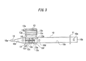
- Fig. 3 illustrates a plan view of the nozzle body 10.
- the intraocular lens 2 is set to the stage portion 12. Moreover, the intraocular lens 2 is pressed by the plunger 30 in that state and extruded from the leading end portion 10a.
- a through hole 10c in which the cross-sectional shape varies in response to changes in the external form of the nozzle body 10, is provided inside the nozzle body 10.
- the intraocular lens 2 when the intraocular lens 2 is extruded, the intraocular lens 2 is deformed in response to changes in the cross-sectional shape of the through hole 10c in the nozzle body 10, is deformed into a shape which easily enters the incision formed in the patient's eyeball, and then is extruded.
- the stage portion 12 is formed with a stage groove 12a having a width that is slightly larger than the diameter of the lens main body 2a of the intraocular lens 2.
- a dimension in the front and rear direction of the stage groove 12a is set to be larger than the maximum width dimension including the support portions 2b and 2b which extend to either side of the intraocular lens 2.
- a set surface 12b is formed by the bottom surface of the stage groove 12a.
- a vertical position (a position in a direction perpendicular to the sheet surface of Fig. 3 ) of the set surface 12b is set above the height position of the bottom surface of the through hole 10c of the nozzle body 10 (front side in the direction perpendicular to the sheet surface of Fig.
- the stage portion 12 and the stage lid portion 13 are integrally formed.
- the stage lid portion 13 has a dimension in the front and rear direction that is equivalent to the stage portion 12.
- the stage lid portion 13 is connected by a thin plate-shaped connecting portion 14 that is formed by extending the side surface of the stage portion 12 to the stage lid portion 13 side.
- the connecting portion 14 is flexibly formed in a central portion, and the stage lid portion 13 is adapted to be able to overlap and close the stage portion 12 from the upper side, by bending the connecting portion 14.
- stage lid portion 13 On a surface facing the set surface 12b during closing, ribs 13a and 13b are provided to reinforce the stage lid portion 13 and stabilize the position of the intraocular lens 2.
- a guide projection 13c is provided as an upper guide of the plunger 30.
- Figs. 4 (a) and 4 (b) illustrate schematic configurations of the positioning member 50.
- Fig. 4(a) illustrates a plan view
- Fig. 4 (b) illustrates a side view.
- the positioning member 50 is configured separately from the nozzle body 10, and has a structure in which a pair of side wall portions 51 and 51 is provided perpendicular to a connecting portion 52 on both right and left sides of the plate-shaped connecting portion 52. From the lower end of each side wall portion 51, holding portions 53 and 53 as gripping portions are provided to extend outward and spread.
- first positioning portions 54 and 54 protruding upward is formed. Furthermore, in a portion of the outer circumferential side of the first placing portion 54, first positioning portions 55 and 55 are formed to protrude further upward.
- An inner wall of the first positioning portion 55 has a circular arc shape, a distance between the inner walls is set to be slightly larger than the diameter dimension of the lens main body 2a of the intraocular lens 1. Also, the first positioning portions 55 and 55 are formed with support portion grooves 55a and 55a as groove portions for receiving the support portions 2b and 2b when placing the intraocular lens 2.
- a pair of second placing portions 56 and 56 is formed at the diagonal positions opposite to the first placing portions 54 and 54 of the connecting portion 52.
- the height of the top surface of the second placing portion 56 is equal to the height of the top surface of the first placing portion 54.
- second positioning portions 57 and 57 are formed to further protrude upward.
- the inner wall of the second positioning portion 57 also has a circular arc shape, and a distance between the inner walls is set to be slightly larger than the diameter of the lens main body 2a of the intraocular lens 2.
- locking claws 58 and 58 are formed to slightly protrude.
- the positioning member 50 is assembled from the lower side of the set surface 12b of the nozzle body 10.
- a set surface through hole 12c penetrating through the set surface 12b in the thickness direction is formed on the set surface 12b of the nozzle body 10.
- the external form of the set surface through hole 12c has an approximately similar shape that is slightly larger than a shape when the first placing portion 54 and the second placing portion 56 of the positioning member 50 are viewed from the top.
- the positioning member 50 is attached to the nozzle body 10
- the first placing portions 54 and 54 and the second placing portions 56 and 56 are inserted into the set surface through hole 12c from the lower side of the set surface 12b, and protrude to the upper side of the set surface 12b.
- the positioning member 50 is assembled from the lower side of the nozzle body 10, the first placing portions 54 and 54 and the second placing portions 56 and 56 are fixed in a state of protruding from the set surface 12b.
- the outer circumference bottom surface of the lens main body 2a is placed on the top surfaces of the first placing portions 54 and 54 and the second placing portion 56 and 56.
- the position of the lens main body 2a is restricted with respect to the horizontal direction, by the first positioning portions 55 and 55 and the second positioning portions 57 and 57. Furthermore, at that time, the vicinity of the base of the support portions 2b and 2b is supported so as to pass through the support portion grooves 55a and 55a, and the rotation around the optical axis of the intraocular lens 2 is restricted.
- the first placing portion 54, the second placing portion 56, the first positioning portion 55 and the second positioning portion 57 in this example correspond to the convex portions.
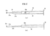
- Figs. 5(a) and 5(b) illustrate schematic configurations of the plunger 30.
- the plunger 30 has a length in the front and rear direction that is slightly larger than the nozzle body 10.
- the plunger is formed from an acting portion 31 of the leading end side based on a cylindrical shape, and an insertion portion 32 of the rear end side based on a rectangular rod shape.
- the acting portion 31 is configured to include a cylindrical portion 31a having a cylindrical shape, and a thin plate-shaped flat portion 31b extending in the leftward and rightward direction of the cylindrical portion 31a.
- a notch portion 31c is formed at the leading end portion of the acting portion 31.
- the notch portion 31c is formed in a groove shape that opens in the upward direction and passes in the leftward and rightward direction of the acting portion 31.
- the groove wall of the leading end side of the notch portion 31c is formed by the inclined surface toward the upper part as it goes to the leading end side of the acting portion 31.
- the insertion portion 32 has a generally H-shaped cross-section as a whole, the dimensions thereof in the upward and downward direction and the leftward and rightward direction are set to be slightly smaller than the through hole 10c of the nozzle body 10.
- a disk-shaped pressing plate portion 33 extending in the upward, downward, leftward and rightward direction the vertical and horizontal directions is formed.
- a claw portion 32a is formed which protrudes toward the upper side of the insertion portion 32 and is vertically movable by elasticity of the material of the plunger 30. Moreover, when the plunger 30 is inserted into the nozzle body 10, a locking hole 10e illustrated in Fig. 3 provided in the thickness direction on the top surface of the nozzle body 10 engages with the claw portion 32a, and thus, the relative position between the nozzle body 10 and the plunger 30 in the initial state is determined.
- the formation positions of the claw portion 32a and the locking hole 10e are set so that, in the engaged state, the leading end of the acting portion 31 is positioned behind the lens main body 2a of the intraocular lens 2 set on the stage portion 12, and is positioned at a location where the notch portion 31c can support the rear support portion 2b of the lens main body 2a from the lower side.
- the plunger 30 Prior to use of the insertion tool 1 configured as described above, the plunger 30 is inserted into the nozzle body 10 and disposed at the initialposition. Furthermore, as described above, the positioning member 50 is attached to the nozzle body 10 from the lower side of the set surface 12b. Thus, the first placing portion 54 and the second placing portion 56 of the positioning member 50 are held in a state that protrudes from the set surface 12b.
- the lens main body 2a of the intraocular lens 2 is placed and positioned on the top surfaces of the first placing portion 54 and the second placing portion 56 in the state of causing the support portions 2b and 2b to face in the front and rear direction of the nozzle body 10.
- the central portion is supported in a non-load state.
- the support portion 2b of the intraocular lens 2 is also supported by the bottom surface of the notch portion 31c of the plunger 30, other than the support portion grooves 55a and 55a.
- the positioning member 50 is detached from the nozzle body 10.
- the first placing portion 54 and the second placing portion 56 supporting the lens main body 2a of the intraocular lens 2 are retracted from the set surface 12b, the intraocular lens 2 is movably placed on the set surface 12b, and the restrictions on the position and posture of the intraocular lens 2 are released.
- the leading end portion 10a of the nozzle portion 15 of the nozzle body 10 is inserted into the incision provided in the eye tissue.
- the leading end portion 10a has an oblique opening shape, it is possible to easily perform the insertion into the incision.
- the pressing plate portion 33 of the plunger 30 is pushed to the leading end side of the nozzle body 10.
- the leading end of the acting portion 31 of the plunger 30 abuts against the outer circumference of the lens main body 2a of the intraocular lens 2 set on the set surface 12a, and the intraocular lens 2 moves toward the leading end portion 10a along with the advancement of the plunger 30.
- the intraocular lens 2 when the intraocular lens 2 is pressed by the plunger 30 and the nozzle body 10 moves forward, the intraocular lens 2 is deformed in response to changes in the cross-sectional shape of the through hole 10c, the intraocular lens 2 is extruded into the eyeball from the leading end portion 10a of the nozzle body 10 in the deformed state.
- the positioning member 50 is provided with an anti-rotation wall portion that suppresses the rotation around the axis in the direction of movement of the intraocular lens 2 at the time of detachment.
- Figs. 6(a) and 6(b) illustrate a positioning member 60 in this example.
- the positioning member 60 differs from the positioning member 50 illustrated in Figs. 4(a) and 4(b) in that anti-rotation wall portions 59 and 59 are provided on the outside of the respective side wall portions 51 and 51.
- the anti-rotation wall portions 59 and 59 are provided for the entire area in the front and rear direction of the positioning member 60 to be parallel to the side wall portions 51 and 51.
- rib groove portions 61 and 61 configured to house a rib portion 12g of the stage portion 12 of the nozzle body 10 are formed between the side wall portion 51 and the anti-rotation wall portion 59 as described below.
- Figs. 7(a) and 7(b) illustrate diagrams of the case of applying the positioning member 60 of this example to the intraocular lens insertion tool 1. Unlike Figs. 1(a) and 1(b) , it is understood that the anti-rotation wall portion 59 is disposed to be exposed to the outside of the right and left sides of the stage portion 12. Furthermore, Figs. 8(a) and 8(b) illustrate diagrams of the vicinity of the positioning member 60 in the case of applying the positioning member 60 in this example to the intraocular lens insertion tool 1. Fig. 8 (a) illustrates the side view, and Fig. 8(b) illustrates an A-A cross-section thereof.
- the rib portions 12g and 12g as the flat plate portions are provided on the right and left lower sides of the set surface 12b in the stage portion 12 of the nozzle body 10.
- the rib portion 12g is viewed from the side surface, as illustrated in Fig. 8(a) , the height of the leading end side thereof increases like a taper, and the rear side thereof has a constant height.
- the positioning member 60 in this example is fixed in the state of housing the respective rib portions 12g between the respective side wall portions 51 and 51 and the respective anti-rotation wall portions 59 and 59, when it is mounted to the stage portion 12 from the lower side.
- the distance between the respective side wall portions 51 and 51 and the respective anti-rotation wall portions 59 and 59 is set to be slightly larger than the thickness of the respective rib portions 12g and 12g.
- the operation of housing the rib portion 12g in the rib groove portion 61 between the side wall portion 51 and the anti-rotation wall portion 59 corresponds to the operation of suppressing the rotation of the positioning member, by causing the two wall surfaces formed parallel to the flat plate portion to face the flat plate portion from both sides in this example.
- the rotation suppressing means in this example is configured to include the side wall portions 51 and 51, the anti-rotation wall portions 59 and 59, and the rib groove portions 61 and 61. Furthermore, in this example, the side wall portions 51 and 51, the anti-rotation wall portions 59 and 59, and the rib groove portions 61 and 61 are disposed on both sides of the intraocular lens center. Thus, the rotation suppressing means in this example are provided on both sides with respect to the central axis in the direction of movement of the intraocular lens, when viewed from the direction of optical axis of the intraocular lens.
- the rib portions 12g and 12g are provided on the right and left lower sides of the set surface 12b in the stage portion 12 of the nozzle body 10, and the positioning member 60 is provided with the anti-rotation wall portions 59 and 59 on the outer side of the respective side wall portions 51 and 51. Moreover, the positioning member 60 is fixed in the state in which the respective rib portions 12g and 12g are housed between the respective side wall portions 51 and 51 and the respective anti-rotation wall portions 59 and 59, when it is attached to the stage portion 12 from the lower side.
- anti-rotation rib portions 12h and 12h are provided inside the rib portions 12g and 12g.
- a positioning member 65 is not provided withtheanti-rotationwallportion. Moreover, when the positioning member 65 is attached to the stage portion 12 from the lower side, it is fixed in a state in which the respective side wall portions 51 and 51 are housed in side wall groove portions 12k and 12k between the respective rib portions 12g and 12g and the respective anti-rotation rib portions 12h and 12h.
- the operation of housing the side wall portion 51 in the side wall groove portion 12k between the rib portion 12g and the anti-rotation rib portion 12h corresponds to the operation of suppressing the rotation of the positioning member, by causing the two wall surfaces formed parallel to the flat plate portion to face the flat plate portion from both sides in this example.
- the rotation suppressing means in this example is configured to include the rib portions 12g and 12g, the anti-rotation rib portions 12h and 12h, and the side wall groove portions 12k and 12k.
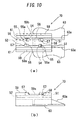
- Figs. 10 (a) and 10(b) illustrate a schematic configuration of a positioning member 70 in this example.
- Fig. 10(a) illustrates a plan view
- Fig. 10(b) illustrates a side view
- Figs. 11 (a) and 11 (b) illustrate perspective views of the positioning member 70.
- Fig. 11 (a) is a perspective view when viewed from the upper rear side
- Fig. 11(b) is a perspective view when viewed from the lower front side thereof.
- the positioning member 70 differs from the positioning member 60 described in Figs. 6 (a) and 6(b) in that, in the positioning member 70, holding portions 63 and 63 as the gripping portions are provided so as to be biased to the rear side from the center in the front and rear direction of the positioning member 70.
- Figs. 12(a) and 12(b) illustrate overall views of the case of applying the positioning member 70 of this example to the intraocular lens insertion tool 1.
- the locking claws 58 and 58 provided on the second positioning portions 57 and 57 as described above are locked to the top surface of the set surface 12b, and thus, the positioning member 70 is mounted to the nozzle body 10.
- the holding portion 63 is provided so as to be biased to the rear side from the junction of the positioning member 70 with the nozzle body 10.
- the holding portion 63 is provided so as to be biased to the rear side from the junction of the positioning member 70 with the nozzle body 10.
- concave portions 59a and 59b are provided, respectively.
- the length in the front and rear direction of the concave portion 59a is formed to be longer than the length in the front and rear direction of the concave portion 59b. This is configured so that a nozzle snap fit 13e of the lid portion 13 as illustrated in Figs. 12 (a) and 12 (b) can escape from the concave portion 59a but does not escape from the concave portion 59b.
- the holding portion 63 is positioned so as to be biased to the rear side from the center in the front and rear direction of the positioning member 70, by viewing the position of the holding portion 63, it is also possible to more easily prevent the erroneous mounting of the positioning member 70.
- Figs. 13 (a) to 13 (g) are six-sided views of the positioning member 70 in this example: Fig. 13(a) is a plan view; Fig. 13 (b) is a bottom view; Fig. 13 (c) is a front view; Fig. 13 (d) is a rear view; Fig. 13 (e) is a left side view; Fig. 13(f) is a right side view; and Fig. 13(g) illustrates a perspective view.
- Figs. 14 (a) to 14 (g) illustrate characteristic portions (partial design) of an external diagram of the positioning member 70 by a solid line, and illustrates other portions by a broken line.
- Fig. 14(a) is a plan view
- Fig. 14(b) is a bottom view
- Fig. 14 (c) is a front view
- Fig. 14 (d) is a rear view
- Fig. 14(e) is a left side view
- Fig. 14 (f) is a right side view
- Fig. 14 (g) illustrates a perspective view.
- the rotation suppressing means is configured to include the side wall portions 51 and 51, the anti-rotation wall portions 59 and 59, and the rib groove portions 61 and 61. Furthermore, in this example, the side wall portions 51 and 51, the anti-rotation wall portions 59 and 59, and the rib groove portions 61 and 61 are disposed on both sides of center of the intraocular lens. Thus, the rotation suppressing means in this example are provided on both sides with respect to the central axis in the direction of movement of the intraocular lens, when viewed from the optical axis of the intraocular lens.
- the intraocular lens to be inserted an example of using a so-called three-piece type in which the lens main body (optical portion) and the support portion are made of different materials has been described.
- the invention it is also possible to apply the invention to an insertion tool for inserting a so-called one-piece intraocular lens in which the lens main body (optical portion) and the support portion are integrally formed.
- the shape of the positioning member is not intended to be limited to the shape of the above-described examples, unless it departs from the spirit of the invention.
- an aspect may be adopted in which the length in the front and rear direction of the anti-rotation wall portion does not extend throughout the entire region of the positioning member, or only one anti-rotation wall portion is provided.
- an aspect may be adopted in which the gap between the anti-rotation wall portion and the side wall portion is smaller than the rib thickness, and the rib portion is interposed between the two wall surfaces without a gap.
- the length in the front and rear direction of the anti-rotation rib portion may be equal to or different from the rib portion.
- the anti-rotation rib portion may be provided so as to be divided in the front and rear direction.
- only one anti-rotation rib portion may be provided.
- an aspect may be adopted in which the gap between the anti-rotation rib portion and the rib portion is smaller than the thickness of the side wall portion, and the side wall portion is interposed between the two wall surfaces without a gap.
Landscapes
- Health & Medical Sciences (AREA)
- Ophthalmology & Optometry (AREA)
- Public Health (AREA)
- Life Sciences & Earth Sciences (AREA)
- Veterinary Medicine (AREA)
- Engineering & Computer Science (AREA)
- Biomedical Technology (AREA)
- Heart & Thoracic Surgery (AREA)
- Vascular Medicine (AREA)
- General Health & Medical Sciences (AREA)
- Animal Behavior & Ethology (AREA)
- Oral & Maxillofacial Surgery (AREA)
- Cardiology (AREA)
- Transplantation (AREA)
- Nuclear Medicine, Radiotherapy & Molecular Imaging (AREA)
- Surgery (AREA)
- Prostheses (AREA)
Abstract
Description
- The present invention relates to an intraocular lens insertion tool for inserting an intraocular lens into an eyeball of a patient, and a positioning member provided in the intraocular lens insertion tool.
- Conventionally, in a surgery such as a cataract, a treatment has been performed in which an incision is provided in an ocular tissue such as a cornea (sclera) in the eyeball and a crystalline lens anterior capsule portion, an intracapsular crystalline lens is extracted and removed via the incision, and thereafter, an intraocular lens substituting the crystalline lens is inserted into the eye and disposed in the capsule from the incision.
- Especially, in recent years, when inserting the intraocular lens into the eyeball from the incision, in many cases, an insertion tool as illustrated below is used. That is, a leading end opening of an insertion cylindrical portion provided at a leading end portion of a tool main body is inserted into the eyeball through the incision, and the intraocular lens is extruded from the leading end opening of the insertion cylindrical portion by a rod-shaped plunger in a state of being slightly deformed in the tool main body, thereby inserting the intraocular lens into the eyeball. By using such an insertion tool, since it is possible to simply insert the intraocular lens into the eyeball by the use of the incision formed for extraction and removal of the crystalline lens, it is possible to simplify the surgery, and it is possible to suppress an occurrence of astigmatism and an occurrence of infectious disease after surgery.
- Incidentally, some above-described intraocular lens insertion tools have a positioning member that holds the position and posture of the intraocular lens in the insertion tools while restricting them, and hold the intraocular lens using the positioning member in the state before use. In this type of intraocular lens insertion tool, the restrictions on the position and posture of the intraocular lens are released by removing the positioning member during use, and the intraocular lens is set to an extrudable state by the plunger (for example, see Patent Literature 1). In this case, depending on a method of removing the positioning member, an inconvenience has occurred in which a lens main body or a support portion of the intraocular lens are interposed by some parts of the positioning member, in some cases, it is not possible to normally release the restrictions on the position and posture of the intraocular lens, and it is difficult to smoothly perform the inserting operation of the intraocular lens.
-
- Patent Literature 1:
JP 2008-61677 A - Patent Literature 2:
JP 2010-273986 A - The present invention has been made in view of the above-described conventional problems, and an object thereof is to provide a technique capable of smoothly releasing the restrictions on the position and posture of the intraocular lens without affecting the intraocular lens or the insertion tool itself, when detaching the positioning member from the intraocular lens insertion tool.
- According to the present invention for solving the above-described problems, there is provided an intraocular lens insertion tool that includes a substantially cylindrical tool main body; a housing portion that is provided in the tool main body to house the intraocular lens; a plunger that discharges the intraocular lens into the eyeball from an insertion cylindrical portion, by pressing the intraocular lens housed in the housing portion by a leading end; and a positioning member that restricts an initial position and posture of the intraocular lens by being mounted to the housing portion from the outside, the intraocular lens insertion tool being a type of being used after detaching the positioning member from the housing portion, wherein in one of an outer circumference of the housing portion or the positioning member, a flat plate portion as a flat plate-shaped wall portion extending in a front and rear direction of the tool main body is formed, and in the other of the outer circumference of the housing portion or the positioning member, a wall surface disposed to interpose the flat plate portion in parallel from both sides is formed, thereby suppressing the rotation of the positioning member around a longitudinal axis with respect to the housing portion.
- More particularly, there is provided an intraocular lens insertion tool that includes a tool main body formed in a substantially cylindrical shape that has an insertion cylindrical portion to be inserted into an incision formed in an ocular tissue and a housing portion capable of housing and disposing the intraocular lens; a plunger that moves the intraocular lens inside the tool main body to discharge the intraocular lens into the eyeball from the insertion cylindrical portion, by pressing the intraocular lens housed in the housing portion with a leading end, by being pushed into the tool main body; and a positioning member that restricts an initial position and posture of the intraocular lens within the tool main body by being mounted to the housing portion from the outside, the intraocular lens insertion tool permitting the movement of the intraocular lens and discharging into the eyeball by the plunger, by detaching the positioning member from the housing portion to release the restrictions on the position and posture of the intraocular lens within the tool main body during use, wherein in one of the outer circumference of the housing portion or the positioning member, a flat plate portion as a flat plate-shaped wall portion formed parallel to a direction of movement of the intraocular lens is provided, and in the other of the outer circumference of the housing portion or the positioning member, a rotation suppressing means for suppressing the rotation of the positioning member with respect to the housing portion by causing two wall surfaces formed parallel to the flat plate portion to face the flat plate portion fromboth sides is provided.
- According to this, it is possible to provide a flat plate portion in one of the outer circumference of the housing portion or the positioning member, and causing the two wall surfaces formed in the other of the outer circumference of the housing portion or the positioning member parallel to the flat plate portion to face the flat plate portion from both sides, thus it is possible to dispose the flat plate portion so as to be interposed between the two wall surfaces. Therefore, for example, it is possible to more reliably suppress the rotation of the positioning member with respect to the housing portion, compared to the case of suppressing the rotation by causing the one wall surface to face the flat plate portion from the one side.
- Furthermore, here, the case of causing the two wall surfaces formed parallel to the flat plate portion to face the plate portion from both sides includes the case of causing the two wall surfaces to face the flat plate portion fromboth sides while keeping a gap, and the case of causing the two wall surfaces to face the flat plate portion from both sides without a gap. The presence or absence of the gap or the dimension of the gap is defined by an angle of rotation allowed for the positioning member. In addition, the direction of rotation capable of being suppressed in this case is mainly the rotation around a direction of movement (an axial direction of the plunger or an axial direction of the tool main body) of the intraocular lens. In addition, the outer circumference of the housing portion in the present invention illustrates an outer surface of the housing portion of the tool main body, and, for example, it may be a surface in a direction in which the positioning member should be attached to the outer surface of the housing portion.
- Furthermore, in the present invention, the flat plate portion may be provided on the outer circumference of the housing portion, and the rotation suppressing means may be provided in the positioning member. Originally, since a rib for securing strength of the housing portion is often provided on the outer circumference of the housing portion, according to the present invention, it is possible to utilize the rib originally provided in the housing portion as the flat plate portion as it is.
- Furthermore, in the present invention, the flat plate portion and the rotation suppressing means may be provided on both sides with respect to the central axis of the direction of movement of the intraocular lens, when viewed from a direction of optical axis of the intraocular lens housed in the housing portion. In that case, it is possible to cause each of the two wall surfaces to face the flat plate portion provided at two positions around the axis in the direction of movement of the intraocular lens from both sides, and it is possible to more reliably suppress the rotation of the positioning member with respect to the housing portion.
- Furthermore, in the present invention, the positioning member may have a plurality of convex portions that performs the position restrictions on the intraocular lens, the plurality of convex portions may be inserted into a plurality of holes formed on a placing surface as a surface on which the intraocular lens is placed in the housing portion, and when a locking portion provided on a side surface of the convex portion engages with an end surface of the placing surface forming the hole, the positioning member may be mounted to the housing portion.
- In the intraocular lens insertion tool having such a type of the positioning member, since the positioning member rotates around the axis in the direction of movement of the intraocular lens, the convex portion easily interposes the lens main body or the support portion of the intraocular lens, or damages the housing portion. Therefore, by applying the present invention to the intraocular lens insertion tool having such a type of the positioning member, it is possible to make the effect of the invention more remarkable.
- Furthermore, in the present invention, the intraocular lens may include a lens main body, and a whisker-like support portion extending outward from the outer circumference of the lens main body, a part of the plurality of convex portions may have a groove portion for supporting the support portion, and the groove portion may be formed parallel to the direction of movement of the intraocular lens.
- In such a case, when the positioning member rotates around the axis in the direction of movement of the intraocular lens, in some cases, the groove portion for supporting the support portion is deformed by interference between the convex portion and the housing portion, and interposes the support portion of the intraocular lens. Therefore, by applying the present invention to the intraocular lens insertion tool having such a type of the positioning member, it is possible to suppress the interposition of the support portion of the intraocular lens into the groove portion, and it is possible to make the effect of the invention more remarkable.
- Furthermore, in the present invention, the positioning member may have a gripping portion for gripping when attaching or detaching the positioning member to and from the housing portion, and the gripping portion may be provided to be biased from the center in the direction of movement of the intraocular lens in the positioning member.
- According to this, when a user detaches the positioning member from the housing portion by gripping the gripping portion, structurally, the positioning member easily rotates around the axis in the direction vertical to the direction of movement of the intraocular lens, and by rotating the positioning member around such an axis, the positioning member can be easily detached from the housing portion. As a result, since there is no need for rotation around the axis in the direction of movement of the intraocular lens, it is possible to more reliably suppress the rotation of the positioning member around the axis in the direction of movement of the intraocular lens.
- Furthermore, according to this, when mounting the positioning member to the housing portion, it is possible to suppress mounting in an opposite direction with regard to the direction of movement of the intraocular lens.
- Furthermore, in the present invention, an erroneous mounting prevention portion may be formed in at least a part of the wall surface facing the flat plate portion in the rotation suppressing means, and the erroneous mounting prevention portion prohibits the mounting by interfering with a predetermined portion of the housing portion, when the positioning member is mounted in an opposite direction with regard to the direction of movement of the intraocular lens. According to this, it is possible to more reliably suppress the mounting in the opposite direction with regard to the direction of movement of the intraocular lens when mounting the positioning member to the housing portion.
- In addition, the intraocular lens insertion tool of the present invention may be a preset type insertion tool in which the intraocular lens is housed and the positioning member is mounted in the housing portion in advance in the manufacturing process, and which is distributed in a state in which the intraocular lens is housed and the positioning member is mounted in the housing portion. By applying the above-described invention to such a case, it is possible to further improve the reliability of the preset type insertion tool.
- Furthermore, the present invention may be a positioning member provided in any one of the above-described intraocular lens insertion tools.
- In addition, it is possible to use the above-described means for solving the problems of the present invention in combination as much as possible.
- According to the present invention, when detaching the positioning member from the intraocular lens insertion tool, it is possible to smoothly release the restrictions on the position and posture of the intraocular lens, without affecting the intraocular lens and the insertion tool itself.
-
-
Figs. 1(a) and 1(b) are diagrams illustrating a schematic configuration of a conventional intraocular lens insertion tool. -
Figs. 2(a) and 2(b) are diagrams illustrating a schematic configuration of an intraocular lens. -
Fig. 3 is a diagram illustrating a schematic configuration of a nozzle body. -
Figs. 4(a) and 4(b) are diagrams illustrating a schematic configuration of a conventional positioning member. -
Figs. 5(a) and 5(b) are diagrams illustrating a schematic configuration of a plunger. -
Figs. 6(a) and 6(b) are diagrams illustrating a schematic configuration of the positioning member in a first example of the present invention. -
Figs. 7(a) and 7(b) are diagrams illustrating a schematic configuration of an intraocular lens insertion tool in the first example of the invention. -
Figs. 8 (a) and 8 (b) are diagrams illustrating the vicinity of a positioning member in the intraocular lens insertion tool in the first example of the invention. -
Figs. 9 (a) and 9(b) are diagrams illustrating the vicinity of a positioning member in an intraocular lens insertion tool in a second example of the invention. -
Figs. 10 (a) and 10 (b) are diagrams illustrating a schematic configuration of a positioning member in a third example of the invention. -
Figs. 11 (a) and 11(b) are perspective views of the positioning member in the third example of the invention. -
Figs. 12 (a) and 12 (b) are diagrams illustrating a schematic configuration of the intraocular lens insertion tool in the third example of the invention. -
Figs. 13(a) to 13(g) are external views of the positioning member in the third example of the invention. -
Figs. 14(a) to 14(g) are external views of the positioning member in the third example of the invention. - Hereinafter, embodiments of the invention will be described by referring to the drawings.
-
Figs. 1(a) and 1(b) illustrate schematic configurations of a conventional intraocular lens insertion tool 1 (hereinafter, simply referred to as the insertion tool 1).Fig. 1(a) illustrates a plan view, andFig. 1(b) illustrates a side view. Theinsertion tool 1 has anozzle body 10 as a tool main body, and aplunger 30 which is inserted into thenozzle body 10 so as to be able to reciprocate. In thenozzle body 10, one side formed in a cylindrical shape with a substantially rectangular cross-section (hereinafter, a largely open side is referred to as arear end portion 10b) is largely open, and at an end portion on the other side, anozzle portion 15 as a thinly narrowed insertion cylindrical portion, and an obliquely openleading end portion 10a are included. In addition, hereinafter, a direction from theleading end portion 10a toward therear end portion 10b of thenozzle body 10 or its opposite direction (a direction parallel to the direction of movement of the intraocular lens) is set to a front and rear direction, a direction perpendicular to a sheet surface inFig. 1(a) is set to a upward and downward direction, and a direction perpendicular to the sheet surface inFig. 1(b) is set to a leftward and rightward direction. - In the vicinity of the
rear end portion 10b of thenozzle body 10, ahold portion 11 is integrally provided which protrudes in a plate shape and is caught by a finger when a user pushes theplunger 30 to the leading end side of thenozzle body 10. In addition, on the rear end side of thenozzle portion 15 of thenozzle body 10, astage portion 12 as a housing portion for setting anintraocular lens 2 is provided. Thestage portion 12 is configured so that the upper side (a vertical front side of the sheet surface inFig. 1(a) ) of thenozzle body 10 is open by opening astage lid portion 13. Furthermore, a positioningmember 50 is mounted to thestage portion 12 from the lower side (a vertical back side of the sheet surface inFig. 1(a) ) of thenozzle body 10. By this positioningmember 50, the position and posture of theintraocular lens 2 are restricted within thestage portion 12 before use (during transport), and theintraocular lens 2 is stably held. - That is, in the
insertion tool 1, during manufacture, in a state in which thestage lid portion 13 opens and the positioningmember 50 is attached to thestage portion 12, theintraocular lens 2 is set to thestage portion 12. Moreover, after closing thestage lid portion 13, the insertion tool is shipped and sold. Furthermore, during use, the user detaches thepositioning members 50 while closing thestage lid portion 13 , and then, pushes theplunger 30 to the leading end side of thenozzle body 10. Thus, theintraocular lens 2 is pressed by theplunger 30, and theintraocular lens 2 is extruded from theleading end portion 10a. In addition, thenozzle body 10, theplunger 30, and the positioningmember 50 in theinsertion tool 1 are formed of a resin material such as polypropylene. Polypropylene is a material that has a proven track record in a medical device and has high reliability such as chemical resistance. -
Figs. 2 (a) and 2 (b) are diagrams illustrating a schematic configuration of theintraocular lens 2.Fig. 2 (a) illustrates a plan view, andFig. 2(b) illustrates a side view. Theintraocular lens 2 is formed to have a lensmain body 2a having a predetermined refractive power, and two whisker-like support portions main body 2a to hold the lensmain body 2a within the eyeball. Thesupport portions main body 2a is formed from a flexible resin material. -
Fig. 3 illustrates a plan view of thenozzle body 10. In thenozzle body 10 as described above, theintraocular lens 2 is set to thestage portion 12. Moreover, theintraocular lens 2 is pressed by theplunger 30 in that state and extruded from theleading end portion 10a. In addition, a throughhole 10c, in which the cross-sectional shape varies in response to changes in the external form of thenozzle body 10, is provided inside thenozzle body 10. Moreover, when theintraocular lens 2 is extruded, theintraocular lens 2 is deformed in response to changes in the cross-sectional shape of the throughhole 10c in thenozzle body 10, is deformed into a shape which easily enters the incision formed in the patient's eyeball, and then is extruded. - The
stage portion 12 is formed with astage groove 12a having a width that is slightly larger than the diameter of the lensmain body 2a of theintraocular lens 2. A dimension in the front and rear direction of thestage groove 12a is set to be larger than the maximum width dimension including thesupport portions intraocular lens 2. Furthermore, aset surface 12b is formed by the bottom surface of thestage groove 12a. A vertical position (a position in a direction perpendicular to the sheet surface ofFig. 3 ) of theset surface 12b is set above the height position of the bottom surface of the throughhole 10c of the nozzle body 10 (front side in the direction perpendicular to the sheet surface ofFig. 3 ), and theset surface 12b and the bottom surface of the throughhole 10c are connected by a bottominclined surface 10d. In addition, on theset surface 12b, twoguide portions cylindrical portion 31a to be described below in theplunger 30 are provided. - The
stage portion 12 and thestage lid portion 13 are integrally formed. Thestage lid portion 13 has a dimension in the front and rear direction that is equivalent to thestage portion 12. Thestage lid portion 13 is connected by a thin plate-shaped connectingportion 14 that is formed by extending the side surface of thestage portion 12 to thestage lid portion 13 side. The connectingportion 14 is flexibly formed in a central portion, and thestage lid portion 13 is adapted to be able to overlap and close thestage portion 12 from the upper side, by bending the connectingportion 14. - In the
stage lid portion 13, on a surface facing theset surface 12b during closing,ribs stage lid portion 13 and stabilize the position of theintraocular lens 2. In addition, aguide projection 13c is provided as an upper guide of theplunger 30. - Below the
set surface 12b of thestage portion 12, the positioningmember 50 is detachably provided.Figs. 4 (a) and 4 (b) illustrate schematic configurations of the positioningmember 50.Fig. 4(a) illustrates a plan view, andFig. 4 (b) illustrates a side view. The positioningmember 50 is configured separately from thenozzle body 10, and has a structure in which a pair ofside wall portions portion 52 on both right and left sides of the plate-shaped connectingportion 52. From the lower end of eachside wall portion 51, holdingportions - Moreover, at the diagonal positions in the central portion of the connecting
portion 52, a pair offirst placing portions first placing portion 54,first positioning portions first positioning portion 55 has a circular arc shape, a distance between the inner walls is set to be slightly larger than the diameter dimension of the lensmain body 2a of theintraocular lens 1. Also, thefirst positioning portions support portion grooves support portions intraocular lens 2. - Furthermore, at the diagonal positions opposite to the
first placing portions portion 52, a pair ofsecond placing portions second placing portion 56 is equal to the height of the top surface of thefirst placing portion 54. In addition, on the outer portions of the top surfaces of thesecond placing portions second positioning portions second positioning portion 57 also has a circular arc shape, and a distance between the inner walls is set to be slightly larger than the diameter of the lensmain body 2a of theintraocular lens 2. In addition, at the end portion of the central side of the connectingportion 52 in thesecond placing portions claws - In this example, the positioning
member 50 is assembled from the lower side of theset surface 12b of thenozzle body 10. On theset surface 12b of thenozzle body 10, a set surface throughhole 12c penetrating through theset surface 12b in the thickness direction is formed. The external form of the set surface throughhole 12c has an approximately similar shape that is slightly larger than a shape when thefirst placing portion 54 and thesecond placing portion 56 of the positioningmember 50 are viewed from the top. Moreover, when the positioningmember 50 is attached to thenozzle body 10, thefirst placing portions second placing portions hole 12c from the lower side of theset surface 12b, and protrude to the upper side of theset surface 12b. - At that time, the locking
claws second positioning portions set surface 12b via the set surface throughhole 12c, and are locked to the top surface of theset surface 12b. Therefore, the positioningmember 50 is assembled from the lower side of thenozzle body 10, thefirst placing portions second placing portions set surface 12b. Moreover, when theintraocular lens 2 is set to theset surface 12b, the outer circumference bottom surface of the lensmain body 2a is placed on the top surfaces of thefirst placing portions second placing portion main body 2a is restricted with respect to the horizontal direction, by thefirst positioning portions second positioning portions support portions support portion grooves intraocular lens 2 is restricted. In addition, thefirst placing portion 54, thesecond placing portion 56, thefirst positioning portion 55 and thesecond positioning portion 57 in this example correspond to the convex portions. -
Figs. 5(a) and 5(b) illustrate schematic configurations of theplunger 30. Theplunger 30 has a length in the front and rear direction that is slightly larger than thenozzle body 10. Moreover, the plunger is formed from an actingportion 31 of the leading end side based on a cylindrical shape, and aninsertion portion 32 of the rear end side based on a rectangular rod shape. Moreover, the actingportion 31 is configured to include acylindrical portion 31a having a cylindrical shape, and a thin plate-shapedflat portion 31b extending in the leftward and rightward direction of thecylindrical portion 31a. - At the leading end portion of the acting
portion 31, anotch portion 31c is formed. As can be seen fromFigs. 5(a) and 5(b) , thenotch portion 31c is formed in a groove shape that opens in the upward direction and passes in the leftward and rightward direction of the actingportion 31. Also, as can be seen fromFig. 5(b) , the groove wall of the leading end side of thenotch portion 31c is formed by the inclined surface toward the upper part as it goes to the leading end side of the actingportion 31. - Meanwhile, the
insertion portion 32 has a generally H-shaped cross-section as a whole, the dimensions thereof in the upward and downward direction and the leftward and rightward direction are set to be slightly smaller than the throughhole 10c of thenozzle body 10. In addition, at the rear end of theinsertion portion 32, a disk-shapedpressing plate portion 33 extending in the upward, downward, leftward and rightward direction the vertical and horizontal directions is formed. - In a portion of the leading end side from the center in the front and rear direction of the
insertion portion 32, aclaw portion 32a is formed which protrudes toward the upper side of theinsertion portion 32 and is vertically movable by elasticity of the material of theplunger 30. Moreover, when theplunger 30 is inserted into thenozzle body 10, alocking hole 10e illustrated inFig. 3 provided in the thickness direction on the top surface of thenozzle body 10 engages with theclaw portion 32a, and thus, the relative position between thenozzle body 10 and theplunger 30 in the initial state is determined. In addition, the formation positions of theclaw portion 32a and thelocking hole 10e are set so that, in the engaged state, the leading end of the actingportion 31 is positioned behind the lensmain body 2a of theintraocular lens 2 set on thestage portion 12, and is positioned at a location where thenotch portion 31c can support therear support portion 2b of the lensmain body 2a from the lower side. - Prior to use of the
insertion tool 1 configured as described above, theplunger 30 is inserted into thenozzle body 10 and disposed at the initialposition. Furthermore, as described above, the positioningmember 50 is attached to thenozzle body 10 from the lower side of theset surface 12b. Thus, thefirst placing portion 54 and thesecond placing portion 56 of the positioningmember 50 are held in a state that protrudes from theset surface 12b. - Next, the lens
main body 2a of theintraocular lens 2 is placed and positioned on the top surfaces of thefirst placing portion 54 and thesecond placing portion 56 in the state of causing thesupport portions nozzle body 10. In this state, since the outer circumferential portion of the lensmain body 2a in theintraocular lens 2 comes into contact with thefirst placing portion 54 and thesecond placing portion 56, the central portion is supported in a non-load state. Also, in this state, thesupport portion 2b of theintraocular lens 2 is also supported by the bottom surface of thenotch portion 31c of theplunger 30, other than thesupport portion grooves - When the
intraocular lens 2 is inserted into the eyeball using theinsertion tool 1, first, the positioningmember 50 is detached from thenozzle body 10. Thus, thefirst placing portion 54 and thesecond placing portion 56 supporting the lensmain body 2a of theintraocular lens 2 are retracted from theset surface 12b, theintraocular lens 2 is movably placed on theset surface 12b, and the restrictions on the position and posture of theintraocular lens 2 are released. - Subsequently, the
leading end portion 10a of thenozzle portion 15 of thenozzle body 10 is inserted into the incision provided in the eye tissue. Here, since theleading end portion 10a has an oblique opening shape, it is possible to easily perform the insertion into the incision. Moreover, after inserting thenozzle portion 15 into the incision, in that state, thepressing plate portion 33 of theplunger 30 is pushed to the leading end side of thenozzle body 10. Thus, the leading end of the actingportion 31 of theplunger 30 abuts against the outer circumference of the lensmain body 2a of theintraocular lens 2 set on theset surface 12a, and theintraocular lens 2 moves toward theleading end portion 10a along with the advancement of theplunger 30. - Moreover, when the
intraocular lens 2 is pressed by theplunger 30 and thenozzle body 10 moves forward, theintraocular lens 2 is deformed in response to changes in the cross-sectional shape of the throughhole 10c, theintraocular lens 2 is extruded into the eyeball from theleading end portion 10a of thenozzle body 10 in the deformed state. - Here, in the above-described inserting operation of the
intraocular lens 2, when the positioningmember 50 is detached from thenozzle body 10, in a case where the positioningmember 50 is detached straight in the direction of the optical axis of theintraocular lens 2, in particular, no problems occur. However, for example, when it is detached by twisting so as to rotate around the axis in the front and rear direction (the axis in the direction of movement of the intraocular lens 2) of theinsertion tool 1, there is a risk of damage to thenozzle body 10 or the positioningmember 50 by interference of thefirst placing portion 54 and thesecond placing portion 56 with the end surface of the set surface throughhole 12c. In addition, there is a fear that thefirst placing portion 54 and thesecond placing portion 56 interpose the lensmain body 2a or thesupport portion 2b of theintraocular lens 2. - In particular, in a case where the right and left outer walls of the
first positioning portions first placing portions hole 12c, in some cases, thesupport portion grooves support portions support portion grooves member 50 is detached from thestage portion 12, a situation occurs in which thesupport portions intraocular lens 2 protrude outside of the set surface throughholes 12c, and in some cases, theintraocular lens 2 is damaged, and theinsertion intraocular lens 2 becomes impossible. - Incontrast, in this example, the positioning
member 50 is provided with an anti-rotation wall portion that suppresses the rotation around the axis in the direction of movement of theintraocular lens 2 at the time of detachment.Figs. 6(a) and 6(b) illustrate a positioningmember 60 in this example. The positioningmember 60 differs from the positioningmember 50 illustrated inFigs. 4(a) and 4(b) in thatanti-rotation wall portions side wall portions anti-rotation wall portions member 60 to be parallel to theside wall portions rib groove portions rib portion 12g of thestage portion 12 of thenozzle body 10 are formed between theside wall portion 51 and theanti-rotation wall portion 59 as described below. -
Figs. 7(a) and 7(b) illustrate diagrams of the case of applying the positioningmember 60 of this example to the intraocularlens insertion tool 1. UnlikeFigs. 1(a) and 1(b) , it is understood that theanti-rotation wall portion 59 is disposed to be exposed to the outside of the right and left sides of thestage portion 12. Furthermore,Figs. 8(a) and 8(b) illustrate diagrams of the vicinity of the positioningmember 60 in the case of applying the positioningmember 60 in this example to the intraocularlens insertion tool 1.Fig. 8 (a) illustrates the side view, andFig. 8(b) illustrates an A-A cross-section thereof. - As can be seen from
Fig. 8(b) , on the right and left lower sides of theset surface 12b in thestage portion 12 of thenozzle body 10, therib portions rib portion 12g is viewed from the side surface, as illustrated inFig. 8(a) , the height of the leading end side thereof increases like a taper, and the rear side thereof has a constant height. - The positioning
member 60 in this example is fixed in the state of housing therespective rib portions 12g between the respectiveside wall portions anti-rotation wall portions stage portion 12 from the lower side. In this example, the distance between the respectiveside wall portions anti-rotation wall portions respective rib portions - According to this, as indicated by the arrow in
Fig. 8(b) , in a case where the user of the intraocularlens insertion tool 1 detaches the positioningmember 60 from thenozzle body 10, even when trying to rotate the positioningmember 60 around the axis in the front and rear direction (the axis in the direction of movement of the intraocular lens 2) of thenozzle body 10, it is possible to suppress the positioningmember 60 from rotating too much. In addition, the operation of housing therib portion 12g in therib groove portion 61 between theside wall portion 51 and theanti-rotation wall portion 59 corresponds to the operation of suppressing the rotation of the positioning member, by causing the two wall surfaces formed parallel to the flat plate portion to face the flat plate portion from both sides in this example. - According to this, it is possible to suppress the damage of the
nozzle body 10 or the positioningmember 60 due to interference of thefirst placing portion 54 and thesecond placing portion 56 with the end surface of the set surface throughhole 12c. Furthermore, it is possible to suppress thefirst placing portion 54 and thesecond placing portion 56 from interposing the lensmain body 2a or thesupport portion 2b of theintraocular lens 2. Thus, it is possible to more smoothly or reliably perform the inserting operation of the intraocular lens. - In addition, it is possible to prevent a situation in which the right and left outer walls of the
first positioning portions first placing portions hole 12c, thesupport portion grooves support portions intraocular lens 2 are interposed. As a result, it is possible to prevent a situation in which thesupport portions intraocular lens 2 protrude from the set surface throughhole 12c, when detaching the positioningmember 50. - In addition, the rotation suppressing means in this example is configured to include the
side wall portions anti-rotation wall portions rib groove portions side wall portions anti-rotation wall portions rib groove portions - Next, a second example will be described with reference to
Figs. 9 (a) and (b) . In the first example, therib portions set surface 12b in thestage portion 12 of thenozzle body 10, and the positioningmember 60 is provided with theanti-rotation wall portions side wall portions member 60 is fixed in the state in which therespective rib portions side wall portions anti-rotation wall portions stage portion 12 from the lower side. - In contrast, in this example, on the right and left lower sides of the
set surface 12b in thestage portion 12 of thenozzle body 10, in addition to therib portions anti-rotation rib portions rib portions member 65 is not provided withtheanti-rotationwallportion. Moreover, when the positioningmember 65 is attached to thestage portion 12 from the lower side, it is fixed in a state in which the respectiveside wall portions wall groove portions respective rib portions anti-rotation rib portions - With this configuration, in a case where the user of the intraocular
lens insertion tool 1 detaches the positioningmember 65 from thenozzle body 10, as indicated by the arrow inFig. 9(b) , even when trying to rotate the positioningmember 65 around the axis in the front and rear direction (the axis in the direction of movement of the intraocular lens 2) of thenozzle body 10, it is possible to suppress the positioningmember 65 from rotating too much. In addition, the operation of housing theside wall portion 51 in the sidewall groove portion 12k between therib portion 12g and theanti-rotation rib portion 12h corresponds to the operation of suppressing the rotation of the positioning member, by causing the two wall surfaces formed parallel to the flat plate portion to face the flat plate portion from both sides in this example. - Furthermore, with this configuration, it is also possible to suppress the damage of the
nozzle body 10 or the positioningmember 65 due to interference of thefirst placing portion 54 and thesecond placing portion 56 with the end surface of the set surface throughhole 12c. Furthermore, it is possible to suppress thefirst placing portion 54 and thesecond placing portion 56 from interposing the lensmain body 2a and thesupport portion 2b of theintraocular lens 2. Thus, it is possible to more smoothly or reliably perform the inserting operation of the intraocular lens. - In addition, it is possible to prevent the situation in which the right and left outer walls of the
first positioning portions first placing portions holes 12c, thesupport portion grooves support portions intraocular lens 2 are interposed. As a result, it is possible to prevent a situation in which thesupport portions intraocular lens 2 protrude from the set surface throughhole 12c, when detaching the positioningmember 65. - In addition, the rotation suppressing means in this example is configured to include the
rib portions anti-rotation rib portions wall groove portions - Next, a third example of the invention will be described. In this example, an example will be described in which, by disposing the holding portion of the positioning member on the rear side of the center in the front and rear direction of the member, while preventing the rotation about the axis in the front and rear direction of the nozzle body 10 (the direction of movement of the intraocular lens), the rotation about the axis in the leftward and rightward direction of the
nozzle body 10 is allowed, and the positioning member can be more easily detached. -
Figs. 10 (a) and 10(b) illustrate a schematic configuration of a positioningmember 70 in this example.Fig. 10(a) illustrates a plan view, andFig. 10(b) illustrates a side view. Furthermore,Figs. 11 (a) and 11 (b) illustrate perspective views of the positioningmember 70.Fig. 11 (a) is a perspective view when viewed from the upper rear side, andFig. 11(b) is a perspective view when viewed from the lower front side thereof. The positioningmember 70 differs from the positioningmember 60 described inFigs. 6 (a) and 6(b) in that, in the positioningmember 70, holdingportions member 70. -
Figs. 12(a) and 12(b) illustrate overall views of the case of applying the positioningmember 70 of this example to the intraocularlens insertion tool 1. The lockingclaws second positioning portions set surface 12b, and thus, the positioningmember 70 is mounted to thenozzle body 10. In this example, therefore, the holdingportion 63 is provided so as to be biased to the rear side from the junction of the positioningmember 70 with thenozzle body 10. As a result, by simply holding and pulling the holdingportion 63 downward by the user, it is possible to detach the positioningmember 70 while rotating it in the direction illustrated by the arrow inFig. 12 (b) (around the axis in the leftward and rightward direction of the nozzle body 10), and it is possible to more easily detach the positioningmember 70. - Moreover, it is possible to urge the user to rotate and detach the holding
portion 63 around the axis in the leftward and rightward direction of thenozzle body 10, and it is possible to suppress the positioningmember 70 from being rotated and detached around the axis in the front and rear direction of thenozzle body 10. When rotating and detaching the positioningmember 70 around the axis in the horizontal direction of thenozzle body 10, since thesupport portion groove 55a rotates in the longitudinal direction, a risk that thesupport portion groove 55a collapses to interpose thesupport portion 2b is significantly lowered. Therefore, in this example, it is possible to more reliably or smoothly perform the inserting operation of theintraocular lens 2. - In addition, in the
anti-rotation wall portions member 70 of this example,concave portions concave portion 59a is formed to be longer than the length in the front and rear direction of theconcave portion 59b. This is configured so that a nozzle snap fit 13e of thelid portion 13 as illustrated inFigs. 12 (a) and 12 (b) can escape from theconcave portion 59a but does not escape from theconcave portion 59b. - According to this configuration, as illustrated in
Fig. 12(b) , when trying to mount the positioningmember 70 in a correct direction, it is possible to mount the positioningmember 70 without interference between theanti-rotation wall portion 59 and the nozzle snap fit 13e. Meanwhile, when trying to mount the positioningmember 70 in an incorrect direction, theanti-rotation wall portion 59 and the nozzle snap fit 13e interfere with each other and the mounting is prohibited. Thus, in the assembling process of the intraocularlens insertion tool 1, it is possible to prevent the erroneous mounting of the positioningmember 70. In addition, in this example, theconcave portions - In addition, in this example, since the holding
portion 63 is positioned so as to be biased to the rear side from the center in the front and rear direction of the positioningmember 70, by viewing the position of the holdingportion 63, it is also possible to more easily prevent the erroneous mounting of the positioningmember 70. -
Figs. 13 (a) to 13 (g) are six-sided views of the positioningmember 70 in this example:Fig. 13(a) is a plan view;Fig. 13 (b) is a bottom view;Fig. 13 (c) is a front view;Fig. 13 (d) is a rear view;Fig. 13 (e) is a left side view;Fig. 13(f) is a right side view; andFig. 13(g) illustrates a perspective view. - In addition,
Figs. 14 (a) to 14 (g) illustrate characteristic portions (partial design) of an external diagram of the positioningmember 70 by a solid line, and illustrates other portions by a broken line. Of course, the entire shape constituted by the characteristic portions and the broken line is also a new part, but it is to clarity the description. InFigs. 14(a) to 14(g), Fig. 14(a) is a plan view;Fig. 14(b) is a bottom view;Fig. 14 (c) is a front view;Fig. 14 (d) is a rear view;Fig. 14(e) is a left side view;Fig. 14 (f) is a right side view; andFig. 14 (g) illustrates a perspective view. - In addition, in this example, the rotation suppressing means is configured to include the
side wall portions anti-rotation wall portions rib groove portions side wall portions anti-rotation wall portions rib groove portions - In each of the above-described examples, as the intraocular lens to be inserted, an example of using a so-called three-piece type in which the lens main body (optical portion) and the support portion are made of different materials has been described. However, it is also possible to apply the invention to an insertion tool for inserting a so-called one-piece intraocular lens in which the lens main body (optical portion) and the support portion are integrally formed. Furthermore, the shape of the positioning member is not intended to be limited to the shape of the above-described examples, unless it departs from the spirit of the invention. As long as the rotation of the positioning member is suppressed, by causing the flat plate portion formed on one of the outer circumference of the housing portion or the positioning member to be faced by the two wall surfaces formed on the other of the outer circumference of the housing portion or the positioning member from both sides, other shapes may be selected.
- For example, an aspect may be adopted in which the length in the front and rear direction of the anti-rotation wall portion does not extend throughout the entire region of the positioning member, or only one anti-rotation wall portion is provided. In addition, an aspect may be adopted in which the gap between the anti-rotation wall portion and the side wall portion is smaller than the rib thickness, and the rib portion is interposed between the two wall surfaces without a gap.
- In addition, the length in the front and rear direction of the anti-rotation rib portion may be equal to or different from the rib portion. Furthermore, the anti-rotation rib portion may be provided so as to be divided in the front and rear direction. In addition, only one anti-rotation rib portion may be provided. In addition, an aspect may be adopted in which the gap between the anti-rotation rib portion and the rib portion is smaller than the thickness of the side wall portion, and the side wall portion is interposed between the two wall surfaces without a gap.
-
- 1
- insertion tool
- 2
- intraocular lens
- 10
- nozzle body
- 10a
- leading end portion
- 10b
- rear end portion
- 10f
- guide portion
- 10g
- contact portion
- 12
- stage portion
- 12b
- set surface
- 12g
- rib portion
- 12h
- anti-rotation rib portion
- 12k
- side wall groove portion
- 13
- stage lid portion
- 13a
- rib
- 13b
- rib
- 13c
- guide projection
- 15
- insertion cylindrical portion
- 30
- plunger
- 31
- acting portion
- 31a
- cylindrical portion
- 31b
- flat portion
- 50, 60, 70
- positioning member
- 51
- side wall portion
- 53, 63
- holding portion
- 59
- anti-rotation wall portion
- 61
- rib groove portion
Claims (9)
- An intraocular lens insertion tool characterized in that:a tool main body formed in a substantially cylindrical shape that has an insertion cylindrical portion to be inserted into an incision formed in an ocular tissue, and a housing portion capable of housing and disposing an intraocular lens;a plunger that moves the intraocular lens inside the tool main body to discharge the intraocular lens into the eyeball from the insertion cylindrical portion, by pressing the intraocular lens housed in the housing portion with a leading end, by being pushed into the tool main body; anda positioning member that restricts an initial position and posture of the intraocular lens within the tool main body by being mounted to the housing portion from the outside,the intraocular lens insertion tool permitting the movement of the intraocular lens and discharging into the eyeball by the plunger, by detaching the positioning member from the housing portion to release the restrictions on the position and posture of the intraocular lens within the tool main body during use,wherein in one of an outer circumference of the housing portion or the positioning member, a flat plate portion as a flat plate-shaped wall portion formed parallel to a direction of movement of the intraocular lens is provided, andin the other of the outer circumference of the housing portion or the positioning member, a rotation suppressing means that suppresses the rotation of the positioning member with respect to the housing portion by causing two wall surfaces formed parallel to the flat plate portion to face the flat plate portion from both sides is provided.
- The intraocular lens insertion tool according to claim 1,
wherein the flat plate portion is provided on the outer circumference of the housing portion, and
the rotation suppressing means is provided in the positioning member. - The intraocular lens insertion tool according to claim 2,
wherein the flat plate portion and the rotation suppressing means are provided on both sides with respect to a central axis in the direction of movement of the intraocular lens, when viewed from a direction of optical axis of the intraocular lens housed in the housing portion. - The intraocular lens insertion tool according to any one of claims 1 to 3,
wherein the positioning member has a plurality of convex portions for restricting the position of the intraocular lens, and
the plurality of convex portions is inserted into a plurality of holes formed on a placing surface as a surface on which the intraocular lens is placed in the housing portion, and when a locking portion provided on a side surface of the convex portion engages with an end surface of the placing surface forming the hole, the positioning member is mounted to the housing portion. - The intraocular lens insertion tool according to claim 4,
wherein the intraocular lens includes a lens main body, and a whisker-like support portion extending outward from the outer circumference of the lens main body,
a part of the plurality of convex portions has a groove portion for supporting the support portion, and
the groove portion is formed parallel to the direction of movement of the intraocular lens. - The intraocular lens insertion tool according to any one of claims 1 to 5,
wherein the positioning member has a gripping portion for gripping when attaching or detaching the positioning member to and from the housing portion, and
the gripping portion is provided to be biased from the center in the direction of movement of the intraocular lens in the positioning member. - The intraocular lens insertion tool according to claim 2,
wherein an erroneous mounting prevention portion is formed in at least a part of the wall surface facing the flat plate portion in the rotation suppressing means, and
the erroneous mounting prevention portion prohibits the mounting by interfering with a predetermined portion of the housing portion, when the positioning member is mounted in an opposite direction with regard to the direction of movement of the intraocular lens. - The intraocular lens insertion tool according to any one of claims 1 to 7,
wherein the intraocular lens insertion tool is a preset type insertion tool in which the intraocular lens is housed and the positioning member is mounted in the housing portion in advance in the manufacturing process, and which is distributed in a state in which the intraocular lens is housed and the positioning member is mounted in the housing portion. - A positioning member provided in the intraocular lens insertion tool according to any one of claims 1 to 8.
Applications Claiming Priority (2)
| Application Number | Priority Date | Filing Date | Title |
|---|---|---|---|
| JP2012147692 | 2012-06-29 | ||
| PCT/JP2013/067933 WO2014003186A1 (en) | 2012-06-29 | 2013-06-28 | Intraocular lens insertion tool, and positioning member provided in intraocular lens insertion tool |
Publications (3)
| Publication Number | Publication Date |
|---|---|
| EP2868295A1 true EP2868295A1 (en) | 2015-05-06 |
| EP2868295A4 EP2868295A4 (en) | 2016-03-30 |
| EP2868295B1 EP2868295B1 (en) | 2020-10-21 |
Family
ID=49783320
Family Applications (1)
| Application Number | Title | Priority Date | Filing Date |
|---|---|---|---|
| EP13809051.9A Active EP2868295B1 (en) | 2012-06-29 | 2013-06-28 | Intraocular lens insertion tool, and positioning member provided in intraocular lens insertion tool |
Country Status (7)
| Country | Link |
|---|---|
| US (1) | US9801759B2 (en) |
| EP (1) | EP2868295B1 (en) |
| JP (1) | JP6254080B2 (en) |
| KR (1) | KR102131470B1 (en) |
| CN (1) | CN104411270B (en) |
| ES (1) | ES2829610T3 (en) |
| WO (1) | WO2014003186A1 (en) |
Cited By (3)
| Publication number | Priority date | Publication date | Assignee | Title |
|---|---|---|---|---|
| EP3547958A4 (en) * | 2017-01-14 | 2019-12-25 | RxSight, Inc. | Intraocular lens inserter cartridge with a trailing haptic protection structure |
| US11013593B2 (en) | 2018-12-02 | 2021-05-25 | Rxsight, Inc. | Light adjustable lens tracking system and method |
| US11083568B2 (en) | 2017-02-07 | 2021-08-10 | Rxsight, Inc. | Intraocular lens inserter cartridge with an IOL-guiding structure |
Families Citing this family (7)
| Publication number | Priority date | Publication date | Assignee | Title |
|---|---|---|---|---|
| US8747465B2 (en) | 2007-05-30 | 2014-06-10 | Hoya Corporation | Intraocular lens insertion device |
| CN105473104B (en) * | 2013-11-15 | 2018-01-09 | 梅迪塞有限公司 | For housing the device of intraocular lens |
| JP6998303B2 (en) * | 2016-06-28 | 2022-01-18 | Hoya株式会社 | Intraocular lens inserter |
| JP7162443B2 (en) | 2018-05-16 | 2022-10-28 | Hoya株式会社 | intraocular ring inserter with container |
| JP7162445B2 (en) | 2018-05-25 | 2022-10-28 | Hoya株式会社 | intraocular lens inserter |
| US11344406B2 (en) * | 2018-12-20 | 2022-05-31 | Alcon Inc. | Cam-actuated optic lockout mechanism |
| KR102630856B1 (en) | 2023-08-25 | 2024-01-30 | 최원석 | Intraocular lens insertion tool |
Family Cites Families (6)
| Publication number | Priority date | Publication date | Assignee | Title |
|---|---|---|---|---|
| US7645300B2 (en) * | 2004-02-02 | 2010-01-12 | Visiogen, Inc. | Injector for intraocular lens system |
| JP4766442B2 (en) * | 2004-12-28 | 2011-09-07 | Hoya株式会社 | Intraocular lens insertion device |
| JP4908977B2 (en) | 2006-09-05 | 2012-04-04 | 興和株式会社 | Intraocular lens insertion device |
| JP5189356B2 (en) | 2007-12-28 | 2013-04-24 | 興和株式会社 | Intraocular lens insertion device |
| JP5501658B2 (en) | 2009-05-29 | 2014-05-28 | 株式会社ニデック | Intraocular lens insertion device |
| ES2617979T3 (en) | 2009-11-17 | 2017-06-20 | Kowa Company Ltd. | Intraocular lens insertion device |
-
2013
- 2013-06-28 KR KR1020157000006A patent/KR102131470B1/en active Active
- 2013-06-28 WO PCT/JP2013/067933 patent/WO2014003186A1/en not_active Ceased
- 2013-06-28 JP JP2014522712A patent/JP6254080B2/en active Active
- 2013-06-28 US US14/411,075 patent/US9801759B2/en active Active
- 2013-06-28 EP EP13809051.9A patent/EP2868295B1/en active Active
- 2013-06-28 CN CN201380034524.6A patent/CN104411270B/en active Active
- 2013-06-28 ES ES13809051T patent/ES2829610T3/en active Active
Cited By (3)
| Publication number | Priority date | Publication date | Assignee | Title |
|---|---|---|---|---|
| EP3547958A4 (en) * | 2017-01-14 | 2019-12-25 | RxSight, Inc. | Intraocular lens inserter cartridge with a trailing haptic protection structure |
| US11083568B2 (en) | 2017-02-07 | 2021-08-10 | Rxsight, Inc. | Intraocular lens inserter cartridge with an IOL-guiding structure |
| US11013593B2 (en) | 2018-12-02 | 2021-05-25 | Rxsight, Inc. | Light adjustable lens tracking system and method |
Also Published As
| Publication number | Publication date |
|---|---|
| KR20150035982A (en) | 2015-04-07 |
| JPWO2014003186A1 (en) | 2016-06-02 |
| US9801759B2 (en) | 2017-10-31 |
| CN104411270B (en) | 2018-01-30 |
| KR102131470B1 (en) | 2020-07-07 |
| EP2868295B1 (en) | 2020-10-21 |
| EP2868295A4 (en) | 2016-03-30 |
| JP6254080B2 (en) | 2017-12-27 |
| WO2014003186A1 (en) | 2014-01-03 |
| ES2829610T3 (en) | 2021-06-01 |
| CN104411270A (en) | 2015-03-11 |
| HK1207280A1 (en) | 2016-01-29 |
| US20150157500A1 (en) | 2015-06-11 |
Similar Documents
| Publication | Publication Date | Title |
|---|---|---|
| EP2868295B1 (en) | Intraocular lens insertion tool, and positioning member provided in intraocular lens insertion tool | |
| EP2926770B1 (en) | Intraocular lens insertion device | |
| US8152817B2 (en) | Intraocular lens insertion tool | |
| EP3025678A1 (en) | Intraocular lens-inserting instrument | |
| JP6379421B2 (en) | Intraocular lens injector | |
| US10195019B2 (en) | Intraocular lens insertion apparatus | |
| EP2653134B1 (en) | Intraocular lens insertion apparatus | |
| JP6057749B2 (en) | Intraocular lens insertion device | |
| JP6524588B2 (en) | Intraocular lens insertion device | |
| HK1207280B (en) | Intraocular lens insertion tool, and positioning member provided in intraocular lens insertion tool | |
| HK1212196B (en) | Intraocular lens insertion device | |
| WO2016080497A1 (en) | Intraocular lens insertion tool | |
| JP2013202073A (en) | Medical needle assembly |
Legal Events
| Date | Code | Title | Description |
|---|---|---|---|
| PUAI | Public reference made under article 153(3) epc to a published international application that has entered the european phase |
Free format text: ORIGINAL CODE: 0009012 |
|
| 17P | Request for examination filed |
Effective date: 20141222 |
|
| AK | Designated contracting states |
Kind code of ref document: A1 Designated state(s): AL AT BE BG CH CY CZ DE DK EE ES FI FR GB GR HR HU IE IS IT LI LT LU LV MC MK MT NL NO PL PT RO RS SE SI SK SM TR |
|
| AX | Request for extension of the european patent |
Extension state: BA ME |
|
| DAX | Request for extension of the european patent (deleted) | ||
| RA4 | Supplementary search report drawn up and despatched (corrected) |
Effective date: 20160229 |
|
| RIC1 | Information provided on ipc code assigned before grant |
Ipc: A61F 2/16 20060101AFI20160223BHEP |
|
| STAA | Information on the status of an ep patent application or granted ep patent |
Free format text: STATUS: EXAMINATION IS IN PROGRESS |
|
| 17Q | First examination report despatched |
Effective date: 20181018 |
|
| GRAP | Despatch of communication of intention to grant a patent |
Free format text: ORIGINAL CODE: EPIDOSNIGR1 |
|
| STAA | Information on the status of an ep patent application or granted ep patent |
Free format text: STATUS: GRANT OF PATENT IS INTENDED |
|
| INTG | Intention to grant announced |
Effective date: 20200624 |
|
| GRAS | Grant fee paid |
Free format text: ORIGINAL CODE: EPIDOSNIGR3 |
|
| GRAA | (expected) grant |
Free format text: ORIGINAL CODE: 0009210 |
|
| STAA | Information on the status of an ep patent application or granted ep patent |
Free format text: STATUS: THE PATENT HAS BEEN GRANTED |
|
| AK | Designated contracting states |
Kind code of ref document: B1 Designated state(s): AL AT BE BG CH CY CZ DE DK EE ES FI FR GB GR HR HU IE IS IT LI LT LU LV MC MK MT NL NO PL PT RO RS SE SI SK SM TR |
|
| REG | Reference to a national code |
Ref country code: GB Ref legal event code: FG4D |
|
| REG | Reference to a national code |
Ref country code: CH Ref legal event code: NV Representative=s name: VALIPAT S.A. C/O BOVARD SA NEUCHATEL, CH Ref country code: CH Ref legal event code: EP |
|
| REG | Reference to a national code |
Ref country code: IE Ref legal event code: FG4D |
|
| REG | Reference to a national code |
Ref country code: DE Ref legal event code: R096 Ref document number: 602013073482 Country of ref document: DE |
|
| REG | Reference to a national code |
Ref country code: AT Ref legal event code: REF Ref document number: 1325048 Country of ref document: AT Kind code of ref document: T Effective date: 20201115 |
|
| REG | Reference to a national code |
Ref country code: NL Ref legal event code: FP |
|
| PG25 | Lapsed in a contracting state [announced via postgrant information from national office to epo] |
Ref country code: NO Free format text: LAPSE BECAUSE OF FAILURE TO SUBMIT A TRANSLATION OF THE DESCRIPTION OR TO PAY THE FEE WITHIN THE PRESCRIBED TIME-LIMIT Effective date: 20210121 Ref country code: PT Free format text: LAPSE BECAUSE OF FAILURE TO SUBMIT A TRANSLATION OF THE DESCRIPTION OR TO PAY THE FEE WITHIN THE PRESCRIBED TIME-LIMIT Effective date: 20210222 Ref country code: RS Free format text: LAPSE BECAUSE OF FAILURE TO SUBMIT A TRANSLATION OF THE DESCRIPTION OR TO PAY THE FEE WITHIN THE PRESCRIBED TIME-LIMIT Effective date: 20201021 Ref country code: FI Free format text: LAPSE BECAUSE OF FAILURE TO SUBMIT A TRANSLATION OF THE DESCRIPTION OR TO PAY THE FEE WITHIN THE PRESCRIBED TIME-LIMIT Effective date: 20201021 Ref country code: GR Free format text: LAPSE BECAUSE OF FAILURE TO SUBMIT A TRANSLATION OF THE DESCRIPTION OR TO PAY THE FEE WITHIN THE PRESCRIBED TIME-LIMIT Effective date: 20210122 |
|
| REG | Reference to a national code |
Ref country code: LT Ref legal event code: MG4D |
|
| PG25 | Lapsed in a contracting state [announced via postgrant information from national office to epo] |
Ref country code: LV Free format text: LAPSE BECAUSE OF FAILURE TO SUBMIT A TRANSLATION OF THE DESCRIPTION OR TO PAY THE FEE WITHIN THE PRESCRIBED TIME-LIMIT Effective date: 20201021 Ref country code: PL Free format text: LAPSE BECAUSE OF FAILURE TO SUBMIT A TRANSLATION OF THE DESCRIPTION OR TO PAY THE FEE WITHIN THE PRESCRIBED TIME-LIMIT Effective date: 20201021 Ref country code: SE Free format text: LAPSE BECAUSE OF FAILURE TO SUBMIT A TRANSLATION OF THE DESCRIPTION OR TO PAY THE FEE WITHIN THE PRESCRIBED TIME-LIMIT Effective date: 20201021 Ref country code: IS Free format text: LAPSE BECAUSE OF FAILURE TO SUBMIT A TRANSLATION OF THE DESCRIPTION OR TO PAY THE FEE WITHIN THE PRESCRIBED TIME-LIMIT Effective date: 20210221 Ref country code: BG Free format text: LAPSE BECAUSE OF FAILURE TO SUBMIT A TRANSLATION OF THE DESCRIPTION OR TO PAY THE FEE WITHIN THE PRESCRIBED TIME-LIMIT Effective date: 20210121 |
|
| REG | Reference to a national code |
Ref country code: ES Ref legal event code: FG2A Ref document number: 2829610 Country of ref document: ES Kind code of ref document: T3 Effective date: 20210601 |
|
| PG25 | Lapsed in a contracting state [announced via postgrant information from national office to epo] |
Ref country code: HR Free format text: LAPSE BECAUSE OF FAILURE TO SUBMIT A TRANSLATION OF THE DESCRIPTION OR TO PAY THE FEE WITHIN THE PRESCRIBED TIME-LIMIT Effective date: 20201021 |
|
| REG | Reference to a national code |
Ref country code: DE Ref legal event code: R097 Ref document number: 602013073482 Country of ref document: DE |
|
| PG25 | Lapsed in a contracting state [announced via postgrant information from national office to epo] |
Ref country code: CZ Free format text: LAPSE BECAUSE OF FAILURE TO SUBMIT A TRANSLATION OF THE DESCRIPTION OR TO PAY THE FEE WITHIN THE PRESCRIBED TIME-LIMIT Effective date: 20201021 Ref country code: EE Free format text: LAPSE BECAUSE OF FAILURE TO SUBMIT A TRANSLATION OF THE DESCRIPTION OR TO PAY THE FEE WITHIN THE PRESCRIBED TIME-LIMIT Effective date: 20201021 Ref country code: SM Free format text: LAPSE BECAUSE OF FAILURE TO SUBMIT A TRANSLATION OF THE DESCRIPTION OR TO PAY THE FEE WITHIN THE PRESCRIBED TIME-LIMIT Effective date: 20201021 Ref country code: LT Free format text: LAPSE BECAUSE OF FAILURE TO SUBMIT A TRANSLATION OF THE DESCRIPTION OR TO PAY THE FEE WITHIN THE PRESCRIBED TIME-LIMIT Effective date: 20201021 Ref country code: RO Free format text: LAPSE BECAUSE OF FAILURE TO SUBMIT A TRANSLATION OF THE DESCRIPTION OR TO PAY THE FEE WITHIN THE PRESCRIBED TIME-LIMIT Effective date: 20201021 Ref country code: SK Free format text: LAPSE BECAUSE OF FAILURE TO SUBMIT A TRANSLATION OF THE DESCRIPTION OR TO PAY THE FEE WITHIN THE PRESCRIBED TIME-LIMIT Effective date: 20201021 |
|
| PLBE | No opposition filed within time limit |
Free format text: ORIGINAL CODE: 0009261 |
|
| STAA | Information on the status of an ep patent application or granted ep patent |
Free format text: STATUS: NO OPPOSITION FILED WITHIN TIME LIMIT |
|
| PG25 | Lapsed in a contracting state [announced via postgrant information from national office to epo] |
Ref country code: DK Free format text: LAPSE BECAUSE OF FAILURE TO SUBMIT A TRANSLATION OF THE DESCRIPTION OR TO PAY THE FEE WITHIN THE PRESCRIBED TIME-LIMIT Effective date: 20201021 |
|
| 26N | No opposition filed |
Effective date: 20210722 |
|
| PG25 | Lapsed in a contracting state [announced via postgrant information from national office to epo] |
Ref country code: AL Free format text: LAPSE BECAUSE OF FAILURE TO SUBMIT A TRANSLATION OF THE DESCRIPTION OR TO PAY THE FEE WITHIN THE PRESCRIBED TIME-LIMIT Effective date: 20201021 |
|
| PG25 | Lapsed in a contracting state [announced via postgrant information from national office to epo] |
Ref country code: SI Free format text: LAPSE BECAUSE OF FAILURE TO SUBMIT A TRANSLATION OF THE DESCRIPTION OR TO PAY THE FEE WITHIN THE PRESCRIBED TIME-LIMIT Effective date: 20201021 |
|
| PG25 | Lapsed in a contracting state [announced via postgrant information from national office to epo] |
Ref country code: MC Free format text: LAPSE BECAUSE OF FAILURE TO SUBMIT A TRANSLATION OF THE DESCRIPTION OR TO PAY THE FEE WITHIN THE PRESCRIBED TIME-LIMIT Effective date: 20201021 |
|
| PG25 | Lapsed in a contracting state [announced via postgrant information from national office to epo] |
Ref country code: LU Free format text: LAPSE BECAUSE OF NON-PAYMENT OF DUE FEES Effective date: 20210628 |
|
| PG25 | Lapsed in a contracting state [announced via postgrant information from national office to epo] |
Ref country code: IE Free format text: LAPSE BECAUSE OF NON-PAYMENT OF DUE FEES Effective date: 20210628 |
|
| PG25 | Lapsed in a contracting state [announced via postgrant information from national office to epo] |
Ref country code: IS Free format text: LAPSE BECAUSE OF FAILURE TO SUBMIT A TRANSLATION OF THE DESCRIPTION OR TO PAY THE FEE WITHIN THE PRESCRIBED TIME-LIMIT Effective date: 20210221 |
|
| PGFP | Annual fee paid to national office [announced via postgrant information from national office to epo] |
Ref country code: NL Payment date: 20220513 Year of fee payment: 10 |
|
| PGFP | Annual fee paid to national office [announced via postgrant information from national office to epo] |
Ref country code: BE Payment date: 20220526 Year of fee payment: 10 |
|
| PG25 | Lapsed in a contracting state [announced via postgrant information from national office to epo] |
Ref country code: HU Free format text: LAPSE BECAUSE OF FAILURE TO SUBMIT A TRANSLATION OF THE DESCRIPTION OR TO PAY THE FEE WITHIN THE PRESCRIBED TIME-LIMIT; INVALID AB INITIO Effective date: 20130628 |
|
| PG25 | Lapsed in a contracting state [announced via postgrant information from national office to epo] |
Ref country code: CY Free format text: LAPSE BECAUSE OF FAILURE TO SUBMIT A TRANSLATION OF THE DESCRIPTION OR TO PAY THE FEE WITHIN THE PRESCRIBED TIME-LIMIT Effective date: 20201021 |
|
| REG | Reference to a national code |
Ref country code: AT Ref legal event code: UEP Ref document number: 1325048 Country of ref document: AT Kind code of ref document: T Effective date: 20201021 |
|
| REG | Reference to a national code |
Ref country code: NL Ref legal event code: MM Effective date: 20230701 |
|
| REG | Reference to a national code |
Ref country code: BE Ref legal event code: MM Effective date: 20230630 |
|
| PG25 | Lapsed in a contracting state [announced via postgrant information from national office to epo] |
Ref country code: NL Free format text: LAPSE BECAUSE OF NON-PAYMENT OF DUE FEES Effective date: 20230701 |
|
| PG25 | Lapsed in a contracting state [announced via postgrant information from national office to epo] |
Ref country code: MK Free format text: LAPSE BECAUSE OF FAILURE TO SUBMIT A TRANSLATION OF THE DESCRIPTION OR TO PAY THE FEE WITHIN THE PRESCRIBED TIME-LIMIT Effective date: 20201021 |
|
| PG25 | Lapsed in a contracting state [announced via postgrant information from national office to epo] |
Ref country code: BE Free format text: LAPSE BECAUSE OF NON-PAYMENT OF DUE FEES Effective date: 20230630 |
|
| PG25 | Lapsed in a contracting state [announced via postgrant information from national office to epo] |
Ref country code: TR Free format text: LAPSE BECAUSE OF FAILURE TO SUBMIT A TRANSLATION OF THE DESCRIPTION OR TO PAY THE FEE WITHIN THE PRESCRIBED TIME-LIMIT Effective date: 20201021 |
|
| PG25 | Lapsed in a contracting state [announced via postgrant information from national office to epo] |
Ref country code: MT Free format text: LAPSE BECAUSE OF FAILURE TO SUBMIT A TRANSLATION OF THE DESCRIPTION OR TO PAY THE FEE WITHIN THE PRESCRIBED TIME-LIMIT Effective date: 20201021 |
|
| PGFP | Annual fee paid to national office [announced via postgrant information from national office to epo] |
Ref country code: ES Payment date: 20250701 Year of fee payment: 13 |
|
| PGFP | Annual fee paid to national office [announced via postgrant information from national office to epo] |
Ref country code: CH Payment date: 20250701 Year of fee payment: 13 |
|
| REG | Reference to a national code |
Ref country code: CH Ref legal event code: U11 Free format text: ST27 STATUS EVENT CODE: U-0-0-U10-U11 (AS PROVIDED BY THE NATIONAL OFFICE) Effective date: 20260701 |
|
| PGFP | Annual fee paid to national office [announced via postgrant information from national office to epo] |
Ref country code: GB Payment date: 20260511 Year of fee payment: 14 |
|
| PGFP | Annual fee paid to national office [announced via postgrant information from national office to epo] |
Ref country code: IT Payment date: 20260522 Year of fee payment: 14 |
|
| PGFP | Annual fee paid to national office [announced via postgrant information from national office to epo] |
Ref country code: DE Payment date: 20260430 Year of fee payment: 14 |
|
| PGFP | Annual fee paid to national office [announced via postgrant information from national office to epo] |
Ref country code: AT Payment date: 20260527 Year of fee payment: 14 |
|
| PGFP | Annual fee paid to national office [announced via postgrant information from national office to epo] |
Ref country code: FR Payment date: 20260511 Year of fee payment: 14 |