EP2867588B1 - Direct evaporative air handler - Google Patents
Direct evaporative air handler Download PDFInfo
- Publication number
- EP2867588B1 EP2867588B1 EP13729873.3A EP13729873A EP2867588B1 EP 2867588 B1 EP2867588 B1 EP 2867588B1 EP 13729873 A EP13729873 A EP 13729873A EP 2867588 B1 EP2867588 B1 EP 2867588B1
- Authority
- EP
- European Patent Office
- Prior art keywords
- air
- port
- outdoor
- handler
- drawn
- Prior art date
- Legal status (The legal status is an assumption and is not a legal conclusion. Google has not performed a legal analysis and makes no representation as to the accuracy of the status listed.)
- Active
Links
- 238000001816 cooling Methods 0.000 claims description 28
- 238000000034 method Methods 0.000 claims description 18
- 238000011144 upstream manufacturing Methods 0.000 claims description 14
- 238000007710 freezing Methods 0.000 claims description 6
- 230000008014 freezing Effects 0.000 claims description 6
- XLYOFNOQVPJJNP-UHFFFAOYSA-N water Substances O XLYOFNOQVPJJNP-UHFFFAOYSA-N 0.000 claims description 5
- 230000003750 conditioning effect Effects 0.000 claims description 4
- 238000009736 wetting Methods 0.000 claims description 3
- 238000010586 diagram Methods 0.000 description 9
- 230000001143 conditioned effect Effects 0.000 description 8
- 238000013459 approach Methods 0.000 description 3
- 238000013461 design Methods 0.000 description 3
- 230000008020 evaporation Effects 0.000 description 2
- 238000001704 evaporation Methods 0.000 description 2
- 238000013517 stratification Methods 0.000 description 2
- 238000004378 air conditioning Methods 0.000 description 1
- 238000007599 discharging Methods 0.000 description 1
- 230000008030 elimination Effects 0.000 description 1
- 238000003379 elimination reaction Methods 0.000 description 1
- 238000009434 installation Methods 0.000 description 1
- 239000007788 liquid Substances 0.000 description 1
- 238000012986 modification Methods 0.000 description 1
- 230000004048 modification Effects 0.000 description 1
Images



Classifications
-
- F—MECHANICAL ENGINEERING; LIGHTING; HEATING; WEAPONS; BLASTING
- F24—HEATING; RANGES; VENTILATING
- F24F—AIR-CONDITIONING; AIR-HUMIDIFICATION; VENTILATION; USE OF AIR CURRENTS FOR SCREENING
- F24F6/00—Air-humidification, e.g. cooling by humidification
- F24F6/02—Air-humidification, e.g. cooling by humidification by evaporation of water in the air
-
- F—MECHANICAL ENGINEERING; LIGHTING; HEATING; WEAPONS; BLASTING
- F24—HEATING; RANGES; VENTILATING
- F24F—AIR-CONDITIONING; AIR-HUMIDIFICATION; VENTILATION; USE OF AIR CURRENTS FOR SCREENING
- F24F5/00—Air-conditioning systems or apparatus not covered by F24F1/00 or F24F3/00, e.g. using solar heat or combined with household units such as an oven or water heater
- F24F5/0007—Air-conditioning systems or apparatus not covered by F24F1/00 or F24F3/00, e.g. using solar heat or combined with household units such as an oven or water heater cooling apparatus specially adapted for use in air-conditioning
- F24F5/0035—Air-conditioning systems or apparatus not covered by F24F1/00 or F24F3/00, e.g. using solar heat or combined with household units such as an oven or water heater cooling apparatus specially adapted for use in air-conditioning using evaporation
-
- B—PERFORMING OPERATIONS; TRANSPORTING
- B01—PHYSICAL OR CHEMICAL PROCESSES OR APPARATUS IN GENERAL
- B01F—MIXING, e.g. DISSOLVING, EMULSIFYING OR DISPERSING
- B01F23/00—Mixing according to the phases to be mixed, e.g. dispersing or emulsifying
- B01F23/20—Mixing gases with liquids
- B01F23/21—Mixing gases with liquids by introducing liquids into gaseous media
- B01F23/215—Mixing gases with liquids by introducing liquids into gaseous media by forcing the gas through absorbent pads containing the liquid
-
- F—MECHANICAL ENGINEERING; LIGHTING; HEATING; WEAPONS; BLASTING
- F24—HEATING; RANGES; VENTILATING
- F24F—AIR-CONDITIONING; AIR-HUMIDIFICATION; VENTILATION; USE OF AIR CURRENTS FOR SCREENING
- F24F11/00—Control or safety arrangements
- F24F11/70—Control systems characterised by their outputs; Constructional details thereof
- F24F11/72—Control systems characterised by their outputs; Constructional details thereof for controlling the supply of treated air, e.g. its pressure
- F24F11/74—Control systems characterised by their outputs; Constructional details thereof for controlling the supply of treated air, e.g. its pressure for controlling air flow rate or air velocity
- F24F11/77—Control systems characterised by their outputs; Constructional details thereof for controlling the supply of treated air, e.g. its pressure for controlling air flow rate or air velocity by controlling the speed of ventilators
-
- F—MECHANICAL ENGINEERING; LIGHTING; HEATING; WEAPONS; BLASTING
- F25—REFRIGERATION OR COOLING; COMBINED HEATING AND REFRIGERATION SYSTEMS; HEAT PUMP SYSTEMS; MANUFACTURE OR STORAGE OF ICE; LIQUEFACTION SOLIDIFICATION OF GASES
- F25D—REFRIGERATORS; COLD ROOMS; ICE-BOXES; COOLING OR FREEZING APPARATUS NOT OTHERWISE PROVIDED FOR
- F25D17/00—Arrangements for circulating cooling fluids; Arrangements for circulating gas, e.g. air, within refrigerated spaces
- F25D17/04—Arrangements for circulating cooling fluids; Arrangements for circulating gas, e.g. air, within refrigerated spaces for circulating air, e.g. by convection
- F25D17/06—Arrangements for circulating cooling fluids; Arrangements for circulating gas, e.g. air, within refrigerated spaces for circulating air, e.g. by convection by forced circulation
-
- F—MECHANICAL ENGINEERING; LIGHTING; HEATING; WEAPONS; BLASTING
- F25—REFRIGERATION OR COOLING; COMBINED HEATING AND REFRIGERATION SYSTEMS; HEAT PUMP SYSTEMS; MANUFACTURE OR STORAGE OF ICE; LIQUEFACTION SOLIDIFICATION OF GASES
- F25D—REFRIGERATORS; COLD ROOMS; ICE-BOXES; COOLING OR FREEZING APPARATUS NOT OTHERWISE PROVIDED FOR
- F25D17/00—Arrangements for circulating cooling fluids; Arrangements for circulating gas, e.g. air, within refrigerated spaces
- F25D17/04—Arrangements for circulating cooling fluids; Arrangements for circulating gas, e.g. air, within refrigerated spaces for circulating air, e.g. by convection
- F25D17/06—Arrangements for circulating cooling fluids; Arrangements for circulating gas, e.g. air, within refrigerated spaces for circulating air, e.g. by convection by forced circulation
- F25D17/08—Arrangements for circulating cooling fluids; Arrangements for circulating gas, e.g. air, within refrigerated spaces for circulating air, e.g. by convection by forced circulation using ducts
-
- Y—GENERAL TAGGING OF NEW TECHNOLOGICAL DEVELOPMENTS; GENERAL TAGGING OF CROSS-SECTIONAL TECHNOLOGIES SPANNING OVER SEVERAL SECTIONS OF THE IPC; TECHNICAL SUBJECTS COVERED BY FORMER USPC CROSS-REFERENCE ART COLLECTIONS [XRACs] AND DIGESTS
- Y02—TECHNOLOGIES OR APPLICATIONS FOR MITIGATION OR ADAPTATION AGAINST CLIMATE CHANGE
- Y02B—CLIMATE CHANGE MITIGATION TECHNOLOGIES RELATED TO BUILDINGS, e.g. HOUSING, HOUSE APPLIANCES OR RELATED END-USER APPLICATIONS
- Y02B30/00—Energy efficient heating, ventilation or air conditioning [HVAC]
- Y02B30/54—Free-cooling systems
-
- Y—GENERAL TAGGING OF NEW TECHNOLOGICAL DEVELOPMENTS; GENERAL TAGGING OF CROSS-SECTIONAL TECHNOLOGIES SPANNING OVER SEVERAL SECTIONS OF THE IPC; TECHNICAL SUBJECTS COVERED BY FORMER USPC CROSS-REFERENCE ART COLLECTIONS [XRACs] AND DIGESTS
- Y02—TECHNOLOGIES OR APPLICATIONS FOR MITIGATION OR ADAPTATION AGAINST CLIMATE CHANGE
- Y02B—CLIMATE CHANGE MITIGATION TECHNOLOGIES RELATED TO BUILDINGS, e.g. HOUSING, HOUSE APPLIANCES OR RELATED END-USER APPLICATIONS
- Y02B30/00—Energy efficient heating, ventilation or air conditioning [HVAC]
- Y02B30/70—Efficient control or regulation technologies, e.g. for control of refrigerant flow, motor or heating
Definitions
- This disclosure relates generally to an air handler for conditioning an indoor space, and more specifically to a direct evaporative air handler that can provide supply air to cool and humidify the space under different ambient operating conditions.
- the air handler can be used to condition data centers that require relatively consistent supply air under different ambient conditions, i.e., even during cold during winter months and hot summer months.
- Data centers are used to house electronic devices, such as servers and computer storage devices, which generate a significant amount of heat during operation.
- Direct evaporative air handlers are used to cool data centers by providing a relatively cooler supply air stream to the enclosed space in which the electronic equipment operates.
- the air handler deliver supply air to the data center at a temperature of about 75°F and a humidity in the range of about 25-80%. It can be difficult to control the temperature and humidity of the supply air using direct evaporative systems in some conditions because cooling outdoor air is accomplished with discrete evaporation steps, which can render the air too cool or too humid, for example. Additionally, in very cold weather when the air is dry, it can be difficult to humidify the outdoor air without freezing the evaporative media.
- One approach to improve control of temperature and humidity parameters is to control the amount of the evaporation media that is wetted, so that, depending on the outdoor conditions, only a portion of the total media surface is wetted.
- This method may be configured in either series or parallel split media, and provides cooling in discrete stages. Control of the supply air conditions can be difficult even under this approach. For example, if a control signal is sent to stop wetting the media, the media will remain wet for a significant period (until all of the water has been evaporated) and continue to cool and humidify the outdoor air.
- US 2005/0056042 relates to hydronic rooftop cooling systems.
- US5890372 discloses an air conditioning system utilizing indirect evaporative cooling and/or direct evaporative cooling.
- An air handler is provided to humidify and cool an enclosed space, such as a data center, where the air handler can provide improved control of the supply air temperature and humidity under different ambient conditions.
- a direct evaporative air handler that can condition an enclosed space with supply air.
- the air handler comprises: a direct evaporative cooler; an outdoor air port positioned upstream of the evaporative cooler in an air flow direction, the outdoor air port including a damper that is configured to selectively allow outdoor air to enter the air handler; a return air port positioned upstream of the evaporative cooler in an air flow direction, the return air port including a damper that is configured to selectively allow recirculated air from the enclosed space to enter the air handler; an outdoor air bypass port including a damper that is configured to selectively allow outdoor air to enter the air handler at a position where the outdoor air entering the bypass port will not pass through the evaporative cooler; and a supply fan positioned downstream of the evaporative cooler, wherein the air handler is configured so that outdoor air entering the air handler through the outdoor air port passes through the evaporative cooler, and the recirculated air entering the air handler through the return air
- an air handler in another embodiment, comprises a direct evaporative cooler; an outdoor air port positioned upstream of the evaporative cooler in an air flow direction, the outdoor air port including a damper that is configured to selectively allow outdoor air to enter the air handler and proceed on a flow path that passes through the evaporative cooler; an outdoor air bypass port including a damper that is configured to selectively allow outdoor air to enter the air handler and proceed on a flow path that does not pass through the evaporative cooler; a first return air port including a damper that is configured to selectively allow recirculated air from the enclosed space to enter the air handler and proceed on a flow path that does not pass through the evaporative cooler; a second return air port positioned upstream of the evaporative cooler in an air flow direction, the second return air port including a damper that is configured to selectively allow recirculated air from the enclosed space to enter the air handler and proceed on a flow path that passes through the evaporative cooler
- methods of operating the air handler are provided by selectively controlling the air that is drawn through the several ports of the air handler.
- the air handler and control system of the invention can use direct evaporative cooling to cool and humidify an enclosed space such a data center.
- the design described herein can provide a simple, complete and efficient method for cooling a data center while maintaining the humidity of the conditioned space within appropriate limits.
- the air handler can achieve optimal energy efficiency, minimization of stratification of supply air, improved control of space temperature and humidity under a variety of different ambient conditions, and elimination of freeze risk during cold ambient operation.
- Figs. 1A-3B illustrate three operating modes of air handler 100.
- the air handler 100 includes housing 110, evaporative cooler 120 that is provided within housing 110, outdoor air intake port 130 formed on a rear or upstream side of housing 110, outdoor air bypass port 140 formed on a side of housing 110, first return air port 150 formed on the top side of housing 110, second return air port 160 formed on the top side of housing 110, and supply fan 170 that is positioned at a downstream draw-through position of the air handler 100.
- Building relief fans and/or dampers are typically used as part of a complete building conditioning system and are not shown as part of Figs. 1A-3B .
- the outdoor air intake port 130 is provided on the rear of housing 100 and is positioned upstream, in an air flow direction, of the evaporative cooler 120.
- the outdoor air flowing through port 130 proceeds on a flow path that passes through evaporative cooler 120.
- Port 130 is provided with a damper 134 that can control the amount of air that flows through port 130.
- the air handler 100 can also include air filter 136 that filters incoming outdoor air. The filters 136 may be installed before or after damper 134.
- the outdoor air bypass port 140 is provided on the side of the housing 110 and is positioned downstream, in an air flow direction, of the evaporative cooler 120 so that air flowing through port 140 proceeds on a flow path that does not pass through evaporative cooler 120.
- the bypass port 140 can be positioned anywhere on the housing where the outdoor air coming through port 140 bypasses the evaporative cooler 120.
- Port 140 is similarly provided with damper 144 that can control the amount of air that flows through port 140.
- the air handler 100 can also be provided with air filter 146 to filter air entering through port 140.
- the filters 146 may be installed before or after damper 144. For indoor air handling installations, filters 136 and 146 may be eliminated and total incoming outdoor air may be filtered by a common filter bank prior to entry into ports 130 or 140.
- the first return air port 150 allows air that is being returned or recycled from a conditioned space to be returned to the air handler 100.
- the temperature of return air for most data centers implemented with hot-aisle containment is between 85°F and 105°F.
- the first return air port 150 is provided on the top side of housing 110 and is positioned downstream, in an air flow direction, of evaporative cooler 120 so that air flowing through port 150 proceeds on a flow path that does not pass through evaporative cooler 120.
- the first return air port 150 can be positioned anywhere on the housing 110 where the return air coming through port 150 does not pass through the evaporative cooler 120.
- Port 150 is similarly provided with damper 154 that can control the amount of air that flows through port 150.
- the second return air port 160 also allows recirculated air that is being returned from a conditioned space to be returned to the air handler 100.
- the second return air port 160 is provided on the top side of housing 110 and is positioned upstream, in an air flow direction, of evaporative cooler 120 so that air flowing through port 160 proceeds on a flow path that passes through evaporative cooler 120.
- Port 160 can have a smaller air entrance area than port 150.
- the second return air port 160 has a length that is about half the width of the air handler 100, and port 150 extends across substantially the entire width of the air handler 100.
- the port 160 is positioned so that the center of its air entrance area is positioned proximate to one side of the air handler that is opposite the side of the air handler that includes port 140.
- port 160 can be positioned substantially within one half of the air handler 100 (divided along an air flow direction) and port 140 can be positioned substantially in the other half of the air handler 100.
- positioning port 140 away from port 160 can prevent freezing of liquid in the evaporative cooler during cold ambient conditions.
- the dampers 134, 144, 154, 164 each act as an air valve that can control the flow rate of air through the respective port.
- many dampers have a series of blades that control the flow rate based on rotation angle of the blades.
- the blades can be controlled to be fully closed, fully open, or any angle in between allowing for partial flow through the port.
- the dampers can be open and closed by motors that are automatically controlled, e.g., by a modulating actuator, in response to signals from controller 595 ( Fig. 5 ).
- the evaporative cooler 120 can be provided with one or more cooling stages that can include evaporative cooling media.
- the evaporative media is typically wetted with water, and the air handler can be controlled to wet only a portion of the evaporative media depending on the operation mode. If a plurality of cooling stages are used, they can be positioned in series or parallel, and one or more of the stages can be selectively wetted depending on the operation mode.
- the evaporative cooler 120 includes a first cooling stage 126 that extends over more than half the width of the air handler 100, and further includes a second cooling stage 128 that extends over the remaining width of the air handler 100.
- the second cooling stage 128 is smaller than the first cooling stage 126.
- the second cooling stage 128 is positioned proximate to the second return air port 160.
- the supply fan 170 is positioned at a draw-through position of the air handler 100 and operates to draw air through the open ports of the air handler and to mix different air streams before the air is supplied to the conditioned space.
- the fan 170 promotes mixing of the air streams and reduces air stratification so that the air entering the conditioned space is very uniform in temperature.
- the supply fan 170 can be a variable speed plenum fan that is controlled in response to a controller 595 ( Fig. 5 ) to provide varying quantities of supply air depending on the needs of the conditioned space. For example, in the context of data centers, during times of higher usage the electronic equipment will generate more heat and will require more cooling air.
- a building management system can measure the amount of supply air that is required, e.g., based on information from air pressure sensors in the data center.
- the controller can adjust the speed of the supply fan 170 depending on the amount of air that is required.
- the air handler 100 can be provided with any air mixer that is sufficient to mix the different air streams entering the ports prior to being supplied to the conditioned space as supply air.
- Supply fan 170 may be installed internal to the housing of the air-handler or it may be external (as depicted in figures 1A-3B ) so as to freely discharge air directly into the room. When the fans are external to the housing of the air-handler and freely discharging into the room, the fan wheels of adjacent units may be configured to rotate opposite so as to promote better mixing of the supply air within the room.
- FIG. 1A is a plan view of air handler 100 and Fig. 1B is a side view of air handler 100.
- damper 144 is opened to allow outside air stream 145 to enter through outdoor air bypass port 140 and proceed along a flow path that does not pass through evaporative cooler 120.
- Damper 154 is opened and a return (or recirculation) air stream 155 enters the air handler through first return air port 150 and proceeds along a flow path that does not pass through evaporative cooler 120.
- the return air stream 155 mixes with outdoor air stream 145 and is further mixed by supply fan 170, which then supplies the mixed air as supply air 175 to the data center.
- the supply air temperature can be accurately controlled by mixing different amounts of the return air and outdoor air.
- This mode is useful in cold conditions where the outside air is too cold to be supplied to the data center and needs to be heated, but where there may not be a need to humidify the outdoor air. In this mode, there is no need to wet the evaporative cooling media in evaporative cooler 120 and dampers 134 and 164 can be closed. If, however, the outdoor air does not need to be heated, damper 134 can be opened and the remaining dampers can be closed so that the system is operating in 100% outside air (full economizer) mode.
- an outdoor air bypass port 140 allows the supply fan 170 to operate using minimal power input because the fan does not need to draw as much outdoor air through the evaporative media in the evaporative cooler 120. In this regard, there is a lower pressure drop over the evaporative media, which causes the fan to use less power when it draws air though port 130.
- FIG. 2A is a plan view of air handler 100 and Fig. 2B is a side view of air handler 100.
- damper 144 is opened to allow outside air stream 145 to enter through outdoor air bypass port 140 and proceed along a flow path that does not pass through evaporative cooler 120.
- Damper 154 can be opened to allow return air stream 155 to enter the air handler through first return air port 150 and proceed along a flow path that does not pass through evaporative cooler 120.
- the media in the second cooling stage 128 is wetted, and damper 164 is opened to allow return air stream 165 to enter port 160 and pass through at least the activated second cooling stage 128 of evaporative cooler 120.
- return air stream 165 passes through the wetted media its dry bulb temperature is lowered and the air stream is humidified.
- the air streams 145, 155, and 165 are mixed downstream of the evaporative cooler 120 and further mixed by supply fan 170, which then supplies the mixed air to the data center.
- the supply air temperature and humidity can be accurately controlled by mixing the relatively hotter return air stream 155, the humidified and cooled return air 165, and the cooler outdoor air stream 145.
- This mode is useful in severe winter conditions where the outdoor air is very cold (particularly below freezing) and has low absolute moisture content.
- it is difficult to humidify the supply air when the outdoor air is very cold because passing the outdoor air over the wetted media would result in freezing of the water on the media.
- Some conventional approaches to this problem include preheating the outdoor air before it passes through the evaporative media.
- water can be added to the supply air by humidifying the relatively warmer return air.
- the second return air port 160 can be positioned substantially at one side of the air handler 100 so that the return air stream 165 passes through the wetted second stage 128 while the cold outdoor air stream 145 only mixes with return air downstream of evaporative cooler 120. There is no need to wet the first stage 126 of the evaporative cooler 120 in this mode and damper 134 can be closed.
- FIG. 3A is a plan view of air handler 100 and Fig. 3B is a side view of air handler 100.
- Damper 144 is opened to allow outside air stream 145 to enter through outdoor air bypass port 140 and proceed along a flow path that does not pass through evaporative cooler 120.
- the first cooling stage 126 and the second cooling stage 128 can be wetted, and damper 134 is opened to allow outdoor air stream 135 to enter port 130 and pass through the activated evaporative cooler 120.
- only one of the cooling stages can be wetted.
- the supply air temperature can be accurately controlled by mixing the relatively cooler and more humid air that passes through the evaporative cooler 120 with the outdoor air stream 145 that bypasses the evaporative cooler 120.
- This mode is useful in warmer weather conditions where the outdoor air temperature is hotter than the desired supply air temperature.
- the temperature and humidity of the supply air can be difficult to control in warm conditions because the direct evaporative cooler can reduce the temperature beyond the desired temperature and increase the humidity beyond the desired humidity.
- the outdoor air can be cooled with the direct evaporative media, while the temperature can be accurately controlled by mixing in the relatively dryer and warmer bypass air. The cooling may be restricted so as to limit the humidity of the supply air.
- Fig. 4 illustrates another embodiment of an air handler 400.
- the air handler 400 includes similar features, including a housing 410, evaporative cooler 420 that is provided within housing 410, outdoor air intake port 430 formed on a rear face on the upstream side of air handler 400, outdoor air bypass port 440, first return air port 450 formed on the top side of air handler 400, second return air port 460 formed on the top side of air handler 400, and supply fan 470 that is positioned at a downstream draw-through position of the air handler 400.
- the ports 430, 440, 450, and 460 are provided with dampers that can be automatically controlled.
- Air filters 436, 446 are used to filter the air that respectively enters through the outdoor air intake port 430 and the outdoor air bypass port 440.
- the outdoor air bypass port 440 is positioned on the rear face of the air handler 400 and similarly directs the air in a path that does not pass through the evaporative cooler 420.
- a mechanical cooling coil 480 is arranged upstream of the evaporative cooler 420 in series, which can provide additional cooling to the outdoor air if needed.
- exhaust fan 490 is illustrated, which can exhaust all or a portion of the return air to the outdoors.
- Fig. 5 is a schematic diagram illustrating a control system 500 for controlling air handler 501 with controller 595.
- the controller 595 sends control signals to control the outdoor air intake damper 534, outdoor air bypass damper 544, first return air damper 554, and second return air damper 564.
- the controller can control the operating mode of the air handler 501, and can independently control each of the dampers to modulate the air flow that enters each port of the air handler 501.
- the controller 595 can also send control signals to control the speed of variable speed fan 570 depending on how much supply air 575 is required.
- the controller 595 can also send control signals to control the evaporative cooler so that that the cooler (or particular cooling stages or portions of the cooler) are wetted during different operating modes.
- the controller 595 determines the output control signals based on information it receives from building management system 515, or directly from externally mounted temperature, pressure, or power sensing devices.
- the building management system 515 transmits data from various sensors that can measure pressure and temperature conditions in the conditioned indoor space and outdoor ambient conditions.
Landscapes
- Engineering & Computer Science (AREA)
- Chemical & Material Sciences (AREA)
- Combustion & Propulsion (AREA)
- Mechanical Engineering (AREA)
- General Engineering & Computer Science (AREA)
- Physics & Mathematics (AREA)
- Sustainable Development (AREA)
- Life Sciences & Earth Sciences (AREA)
- Fluid Mechanics (AREA)
- Thermal Sciences (AREA)
- Chemical Kinetics & Catalysis (AREA)
- Air Conditioning Control Device (AREA)
- Central Air Conditioning (AREA)
Description
- This disclosure relates generally to an air handler for conditioning an indoor space, and more specifically to a direct evaporative air handler that can provide supply air to cool and humidify the space under different ambient operating conditions. The air handler can be used to condition data centers that require relatively consistent supply air under different ambient conditions, i.e., even during cold during winter months and hot summer months.
- Data centers are used to house electronic devices, such as servers and computer storage devices, which generate a significant amount of heat during operation. Direct evaporative air handlers are used to cool data centers by providing a relatively cooler supply air stream to the enclosed space in which the electronic equipment operates. Although the operating requirements for air handlers vary depending on the data center, in general, it is preferred that the air handler deliver supply air to the data center at a temperature of about 75°F and a humidity in the range of about 25-80%. It can be difficult to control the temperature and humidity of the supply air using direct evaporative systems in some conditions because cooling outdoor air is accomplished with discrete evaporation steps, which can render the air too cool or too humid, for example. Additionally, in very cold weather when the air is dry, it can be difficult to humidify the outdoor air without freezing the evaporative media.
- One approach to improve control of temperature and humidity parameters is to control the amount of the evaporation media that is wetted, so that, depending on the outdoor conditions, only a portion of the total media surface is wetted. This method may be configured in either series or parallel split media, and provides cooling in discrete stages. Control of the supply air conditions can be difficult even under this approach. For example, if a control signal is sent to stop wetting the media, the media will remain wet for a significant period (until all of the water has been evaporated) and continue to cool and humidify the outdoor air.
-
US 2005/0056042 relates to hydronic rooftop cooling systems.US5890372 discloses an air conditioning system utilizing indirect evaporative cooling and/or direct evaporative cooling. - An air handler is provided to humidify and cool an enclosed space, such as a data center, where the air handler can provide improved control of the supply air temperature and humidity under different ambient conditions.
- According to the invention, a direct evaporative air handler is provided that can condition an enclosed space with supply air. The air handler comprises: a direct evaporative cooler; an outdoor air port positioned upstream of the evaporative cooler in an air flow direction, the outdoor air port including a damper that is configured to selectively allow outdoor air to enter the air handler; a return air port positioned upstream of the evaporative cooler in an air flow direction, the return air port including a damper that is configured to selectively allow recirculated air from the enclosed space to enter the air handler; an outdoor air bypass port including a damper that is configured to selectively allow outdoor air to enter the air handler at a position where the outdoor air entering the bypass port will not pass through the evaporative cooler; and a supply fan positioned downstream of the evaporative cooler, wherein the air handler is configured so that outdoor air entering the air handler through the outdoor air port passes through the evaporative cooler, and the recirculated air entering the air handler through the return air port passes through the evaporative cooler, and wherein the air handler is configured to (i) operate in a mode in which the supply fan mixes air that has been drawn through the outdoor air bypass port with recirculated air that has been drawn through the return air port and passed through the evaporative cooler, and (ii) operate in another mode in which the supply fan mixes air that has been drawn through the outdoor air bypass port with outdoor air that has been drawn through the outdoor air port and passed through the evaporative cooler.
- In another embodiment of the present invention, an air handler is provided that comprises a direct evaporative cooler; an outdoor air port positioned upstream of the evaporative cooler in an air flow direction, the outdoor air port including a damper that is configured to selectively allow outdoor air to enter the air handler and proceed on a flow path that passes through the evaporative cooler; an outdoor air bypass port including a damper that is configured to selectively allow outdoor air to enter the air handler and proceed on a flow path that does not pass through the evaporative cooler; a first return air port including a damper that is configured to selectively allow recirculated air from the enclosed space to enter the air handler and proceed on a flow path that does not pass through the evaporative cooler; a second return air port positioned upstream of the evaporative cooler in an air flow direction, the second return air port including a damper that is configured to selectively allow recirculated air from the enclosed space to enter the air handler and proceed on a flow path that passes through the evaporative cooler; and a supply fan positioned downstream of the evaporative cooler that is configured to draw air through the outdoor air port, outdoor air bypass port, first return air port, and second return air port, wherein the supply fan is configured to mix air in the air handler and provide the mixed air as the supply air, wherein the air handler is configured to (i) operate in a mode in which the supply fan mixes air that has been drawn through the outdoor air bypass port with recirculated air that has been drawn through the second return air port and passed through the evaporative cooler, and (ii) operate in another mode in which the supply fan mixes air that has been drawn through the outdoor air bypass port with outdoor air that has been drawn through the outdoor air port and passed through the evaporative cooler, and (iii) operate in a further mode in which the supply fan mixes air that has been drawn through the outdoor air bypass port with air that has been drawn through the first return air port.
- In other aspects, methods of operating the air handler are provided by selectively controlling the air that is drawn through the several ports of the air handler.
- Exemplary embodiments are described in detail below with reference to the accompanying drawings in which:
-
Figs. 1A and 1B are respectively a plan view diagram and a side view diagram showing operation of an air handler in a first operation mode; -
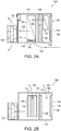
Figs. 2A and 2B are respectively a plan view diagram and a side view diagram showing operation of an air handler in a second operation mode; -
Figs. 3A and 3B are respectively a plan view diagram and a side view diagram showing operation of an air handler in a third operation mode; -
Fig. 4 is a side view cross-sectional diagram of another air handler; and -
Fig. 5 is a schematic diagram illustrating the control system of the air handler. - Exemplary embodiments of the broad principles outlined herein are described with reference to the various drawings.
- The air handler and control system of the invention can use direct evaporative cooling to cool and humidify an enclosed space such a data center. The design described herein can provide a simple, complete and efficient method for cooling a data center while maintaining the humidity of the conditioned space within appropriate limits. Among other advantages, the air handler can achieve optimal energy efficiency, minimization of stratification of supply air, improved control of space temperature and humidity under a variety of different ambient conditions, and elimination of freeze risk during cold ambient operation.
-
Figs. 1A-3B illustrate three operating modes ofair handler 100. Theair handler 100 includeshousing 110,evaporative cooler 120 that is provided withinhousing 110, outdoorair intake port 130 formed on a rear or upstream side ofhousing 110, outdoorair bypass port 140 formed on a side ofhousing 110, firstreturn air port 150 formed on the top side ofhousing 110, secondreturn air port 160 formed on the top side ofhousing 110, andsupply fan 170 that is positioned at a downstream draw-through position of theair handler 100. Building relief fans and/or dampers are typically used as part of a complete building conditioning system and are not shown as part ofFigs. 1A-3B . - The outdoor
air intake port 130 is provided on the rear ofhousing 100 and is positioned upstream, in an air flow direction, of theevaporative cooler 120. The outdoor air flowing throughport 130 proceeds on a flow path that passes throughevaporative cooler 120.Port 130 is provided with adamper 134 that can control the amount of air that flows throughport 130. Theair handler 100 can also includeair filter 136 that filters incoming outdoor air. Thefilters 136 may be installed before or afterdamper 134. - The outdoor
air bypass port 140 is provided on the side of thehousing 110 and is positioned downstream, in an air flow direction, of theevaporative cooler 120 so that air flowing throughport 140 proceeds on a flow path that does not pass throughevaporative cooler 120. Thebypass port 140 can be positioned anywhere on the housing where the outdoor air coming throughport 140 bypasses theevaporative cooler 120.Port 140 is similarly provided withdamper 144 that can control the amount of air that flows throughport 140. Theair handler 100 can also be provided withair filter 146 to filter air entering throughport 140. Thefilters 146 may be installed before or afterdamper 144. For indoor air handling installations,filters ports - The first
return air port 150 allows air that is being returned or recycled from a conditioned space to be returned to theair handler 100. The temperature of return air for most data centers implemented with hot-aisle containment is between 85°F and 105°F. The firstreturn air port 150 is provided on the top side ofhousing 110 and is positioned downstream, in an air flow direction, ofevaporative cooler 120 so that air flowing throughport 150 proceeds on a flow path that does not pass throughevaporative cooler 120. Here also, the firstreturn air port 150 can be positioned anywhere on thehousing 110 where the return air coming throughport 150 does not pass through theevaporative cooler 120.Port 150 is similarly provided withdamper 154 that can control the amount of air that flows throughport 150. - The second
return air port 160 also allows recirculated air that is being returned from a conditioned space to be returned to theair handler 100. The secondreturn air port 160 is provided on the top side ofhousing 110 and is positioned upstream, in an air flow direction, ofevaporative cooler 120 so that air flowing throughport 160 proceeds on a flow path that passes throughevaporative cooler 120.Port 160 can have a smaller air entrance area thanport 150. As can be seen inFigs. 1A ,2A and3A , the secondreturn air port 160 has a length that is about half the width of theair handler 100, andport 150 extends across substantially the entire width of theair handler 100. Theport 160 is positioned so that the center of its air entrance area is positioned proximate to one side of the air handler that is opposite the side of the air handler that includesport 140. Thus,port 160 can be positioned substantially within one half of the air handler 100 (divided along an air flow direction) andport 140 can be positioned substantially in the other half of theair handler 100. As discussed below in greater detail in connection withFigs. 2A and 2B ,positioning port 140 away fromport 160 can prevent freezing of liquid in the evaporative cooler during cold ambient conditions. - The
dampers Fig. 5 ). - The
evaporative cooler 120 can be provided with one or more cooling stages that can include evaporative cooling media. The evaporative media is typically wetted with water, and the air handler can be controlled to wet only a portion of the evaporative media depending on the operation mode. If a plurality of cooling stages are used, they can be positioned in series or parallel, and one or more of the stages can be selectively wetted depending on the operation mode. As can be seen inFig. 1A , in this embodiment theevaporative cooler 120 includes afirst cooling stage 126 that extends over more than half the width of theair handler 100, and further includes asecond cooling stage 128 that extends over the remaining width of theair handler 100. Thesecond cooling stage 128 is smaller than thefirst cooling stage 126. Thesecond cooling stage 128 is positioned proximate to the secondreturn air port 160. - The
supply fan 170 is positioned at a draw-through position of theair handler 100 and operates to draw air through the open ports of the air handler and to mix different air streams before the air is supplied to the conditioned space. Thefan 170 promotes mixing of the air streams and reduces air stratification so that the air entering the conditioned space is very uniform in temperature. Thesupply fan 170 can be a variable speed plenum fan that is controlled in response to a controller 595 (Fig. 5 ) to provide varying quantities of supply air depending on the needs of the conditioned space. For example, in the context of data centers, during times of higher usage the electronic equipment will generate more heat and will require more cooling air. A building management system can measure the amount of supply air that is required, e.g., based on information from air pressure sensors in the data center. The controller can adjust the speed of thesupply fan 170 depending on the amount of air that is required. As an alternative or in addition to thesupply fan 170, theair handler 100 can be provided with any air mixer that is sufficient to mix the different air streams entering the ports prior to being supplied to the conditioned space as supply air.Supply fan 170 may be installed internal to the housing of the air-handler or it may be external (as depicted infigures 1A-3B ) so as to freely discharge air directly into the room. When the fans are external to the housing of the air-handler and freely discharging into the room, the fan wheels of adjacent units may be configured to rotate opposite so as to promote better mixing of the supply air within the room. - A first operation mode of the
air handler 100 is illustrated inFigs. 1A-1B that can be used for supply air temperature control when theevaporative cooler 120 is inactive.Fig. 1A is a plan view ofair handler 100 andFig. 1B is a side view ofair handler 100. In the first operation mode,damper 144 is opened to allowoutside air stream 145 to enter through outdoorair bypass port 140 and proceed along a flow path that does not pass throughevaporative cooler 120.Damper 154 is opened and a return (or recirculation)air stream 155 enters the air handler through firstreturn air port 150 and proceeds along a flow path that does not pass throughevaporative cooler 120. Thereturn air stream 155 mixes withoutdoor air stream 145 and is further mixed bysupply fan 170, which then supplies the mixed air assupply air 175 to the data center. - By modulating
dampers dampers damper 134 can be opened and the remaining dampers can be closed so that the system is operating in 100% outside air (full economizer) mode. - The use of an outdoor
air bypass port 140 allows thesupply fan 170 to operate using minimal power input because the fan does not need to draw as much outdoor air through the evaporative media in theevaporative cooler 120. In this regard, there is a lower pressure drop over the evaporative media, which causes the fan to use less power when it draws air thoughport 130. - A second operation mode of the
air handler 100 is illustrated inFigs. 2A-2B that can be used for supply air temperature and humidity control when theevaporative cooler 120 is active.Fig. 2A is a plan view ofair handler 100 andFig. 2B is a side view ofair handler 100. Similar to the first mode,damper 144 is opened to allowoutside air stream 145 to enter through outdoorair bypass port 140 and proceed along a flow path that does not pass throughevaporative cooler 120.Damper 154 can be opened to allowreturn air stream 155 to enter the air handler through firstreturn air port 150 and proceed along a flow path that does not pass throughevaporative cooler 120. In the second mode, at least the media in thesecond cooling stage 128 is wetted, anddamper 164 is opened to allowreturn air stream 165 to enterport 160 and pass through at least the activatedsecond cooling stage 128 ofevaporative cooler 120. Asreturn air stream 165 passes through the wetted media its dry bulb temperature is lowered and the air stream is humidified. The air streams 145, 155, and 165 are mixed downstream of theevaporative cooler 120 and further mixed bysupply fan 170, which then supplies the mixed air to the data center. - By modulating
dampers return air stream 155, the humidified and cooledreturn air 165, and the cooleroutdoor air stream 145. This mode is useful in severe winter conditions where the outdoor air is very cold (particularly below freezing) and has low absolute moisture content. In this regard, in conventional designs, it is difficult to humidify the supply air when the outdoor air is very cold because passing the outdoor air over the wetted media would result in freezing of the water on the media. Some conventional approaches to this problem include preheating the outdoor air before it passes through the evaporative media. By providing a secondreturn air port 160 upstream of theevaporative cooler 120, water can be added to the supply air by humidifying the relatively warmer return air. - In this embodiment, only the
second stage 128 of theevaporative cooler 120 is wetted, which is positioned on the side of theair handler 100 that isopposite port 140 to prevent the cold outdoor air from freezing the wetted media. Accordingly, as can be seen inFig. 2A , the secondreturn air port 160 can be positioned substantially at one side of theair handler 100 so that thereturn air stream 165 passes through the wettedsecond stage 128 while the coldoutdoor air stream 145 only mixes with return air downstream ofevaporative cooler 120. There is no need to wet thefirst stage 126 of theevaporative cooler 120 in this mode anddamper 134 can be closed. - A third operation mode of the
air handler 100 is illustrated inFigs. 3A-3B that can be used for supply air temperature and humidity control when theevaporative cooler 120 is active.Fig. 3A is a plan view ofair handler 100 andFig. 3B is a side view ofair handler 100.Damper 144 is opened to allowoutside air stream 145 to enter through outdoorair bypass port 140 and proceed along a flow path that does not pass throughevaporative cooler 120. In the third mode, thefirst cooling stage 126 and thesecond cooling stage 128 can be wetted, anddamper 134 is opened to allowoutdoor air stream 135 to enterport 130 and pass through the activatedevaporative cooler 120. Optionally, only one of the cooling stages can be wetted. Asoutdoor air stream 135 passes through the wetted media its dry bulb temperature is lowered and the air stream is humidified. The air streams 135 and 145 are mixed downstream of theevaporative cooler 120 and then further mixed bysupply fan 170, which suppliessupply air 175 to the data center. - By modulating
dampers evaporative cooler 120 with theoutdoor air stream 145 that bypasses theevaporative cooler 120. This mode is useful in warmer weather conditions where the outdoor air temperature is hotter than the desired supply air temperature. In conventional designs that do not mix the bypass outdoor air, the temperature and humidity of the supply air can be difficult to control in warm conditions because the direct evaporative cooler can reduce the temperature beyond the desired temperature and increase the humidity beyond the desired humidity. In this embodiment of the invention, the outdoor air can be cooled with the direct evaporative media, while the temperature can be accurately controlled by mixing in the relatively dryer and warmer bypass air. The cooling may be restricted so as to limit the humidity of the supply air. -
Fig. 4 illustrates another embodiment of an air handler 400. The air handler 400 includes similar features, including ahousing 410,evaporative cooler 420 that is provided withinhousing 410, outdoorair intake port 430 formed on a rear face on the upstream side of air handler 400, outdoorair bypass port 440, first return air port 450 formed on the top side of air handler 400, second return air port 460 formed on the top side of air handler 400, andsupply fan 470 that is positioned at a downstream draw-through position of the air handler 400. Theports Air filters air intake port 430 and the outdoorair bypass port 440. - In this embodiment, the outdoor
air bypass port 440 is positioned on the rear face of the air handler 400 and similarly directs the air in a path that does not pass through theevaporative cooler 420. Amechanical cooling coil 480 is arranged upstream of theevaporative cooler 420 in series, which can provide additional cooling to the outdoor air if needed. In this embodiment,exhaust fan 490 is illustrated, which can exhaust all or a portion of the return air to the outdoors. -
Fig. 5 is a schematic diagram illustrating acontrol system 500 for controllingair handler 501 withcontroller 595. In particular, thecontroller 595 sends control signals to control the outdoorair intake damper 534, outdoorair bypass damper 544, firstreturn air damper 554, and secondreturn air damper 564. As indicated above, the controller can control the operating mode of theair handler 501, and can independently control each of the dampers to modulate the air flow that enters each port of theair handler 501. Thecontroller 595 can also send control signals to control the speed ofvariable speed fan 570 depending on howmuch supply air 575 is required. Thecontroller 595 can also send control signals to control the evaporative cooler so that that the cooler (or particular cooling stages or portions of the cooler) are wetted during different operating modes. - The
controller 595 determines the output control signals based on information it receives frombuilding management system 515, or directly from externally mounted temperature, pressure, or power sensing devices. Thebuilding management system 515 transmits data from various sensors that can measure pressure and temperature conditions in the conditioned indoor space and outdoor ambient conditions. - Although the disclosed devices, systems and methods have been described in conjunction with exemplary embodiments, these embodiments should be viewed as illustrative, not limiting. Various modifications, combinations, substitutes, or the like are possible without departing from the scope of the invention which is defined by the appending claims.
Claims (17)
- A direct evaporative air handler (100) for conditioning an enclosed space with supply air, the air handler comprising:a direct evaporative cooler (120);an outdoor air port (130) positioned upstream of the evaporative cooler (120) in an air flow direction, the outdoor air port (130) including a damper (134) that is configured to selectively allow outdoor air (135) to enter the air handler;a return air port (160) positioned upstream of the evaporative cooler (120) in an air flow direction, the return air port (160) including a damper (164) that is configured to selectively allow recirculated air (165) from the enclosed space to enter the air handler;wherein the air handler is configured so that outdoor air (135) entering the air handler through the outdoor air port (130) passes through the evaporative cooler (120), and the recirculated air (165) entering the air handler through the return air port (160) passes through the evaporative cooler (120), characterized in that the air handler furthermore comprises:an outdoor air bypass port (140) including a damper (144) that is configured to selectively allow outdoor air (145) to enter the air handler at a position where the outdoor air (145) entering the bypass port (140) will not pass through the evaporative cooler (120); anda supply fan (170) positioned downstream of the evaporative cooler (120),wherein the air handler is configured to:(i) operate in a mode in which the supply fan (170) mixes air (145) that has been drawn through the outdoor air bypass port (140) with recirculated air (165) that has been drawn through the return air port (160) and passed through the evaporative cooler (120), and(ii) operate in another mode in which the supply fan (170) mixes air (145) that has been drawn through the outdoor air bypass port (140) with outdoor air (135) that has been drawn through the outdoor air port (130) and passed through the evaporative cooler (120).
- The direct evaporative air handler according to claim 1, wherein each of the dampers (134, 144, 164) is configured to be modulated in response to control signals.
- The direct evaporative air handler according to claim 1, wherein the supply fan (170) is configured to draw air into the air handler, mix the air, and provide the mixed air as the supply air, and wherein the supply fan is preferably a variable speed fan that is configured to change speeds in response to a control signal.
- The direct evaporative air handler according to claim 1, wherein the evaporative cooler (120) includes a plurality of cooling stages (126, 128) that can each be selectively wetted in response to a control signal, wherein one of the plurality of cooling stages (128) is preferably arranged to receive air that enters the air handler through the return air port (160).
- A direct evaporative air handler (100) for conditioning an enclosed space with supply air, the air handler comprising:a direct evaporative cooler (120);an outdoor air port (130) positioned upstream of the evaporative cooler (120) in an air flow direction, the outdoor air port (130) including a damper (134) that is configured to selectively allow outdoor air (135) to enter the air handler and proceed on a flow path that passes through the evaporative cooler (120);an outdoor air bypass port (140) including a damper (144) that is configured to selectively allow outdoor air (145) to enter the air handler and proceed on a flow path that does not pass through the evaporative cooler (120);a first return air port (150) including a damper (154) that is configured to selectively allow recirculated air (155) from the enclosed space to enter the air handler and proceed on a flow path that does not pass through the evaporative cooler (120);a second return air port (160) positioned upstream of the evaporative cooler in an air flow direction, the second return air port (160) including a damper (164) that is configured to selectively allow recirculated air (165) from the enclosed space to enter the air handler and proceed on a flow path that passes through the evaporative cooler (120); anda supply fan (170) positioned downstream of the evaporative cooler (120) that is configured to draw air through the outdoor air port (130), outdoor air bypass port (140), first return air port (150), and second return air port (160), wherein the supply fan is configured to mix air in the air handler and provide the mixed air as the supply air,wherein the air handler is configured to:(i) operate in a mode in which the supply fan (170) mixes air (145) that has been drawn through the outdoor air bypass port (140) with recirculated air (165) that has been drawn through the second return air port (160) and passed through the evaporative cooler (120), and(ii) operate in another mode in which the supply fan (170) mixes air (145) that has been drawn through the outdoor air bypass port (140) with outdoor air (135) that has been drawn through the outdoor air port (130) and passed through the evaporative cooler (120), and(iii) operate in a further mode in which the supply fan (170) mixes air (145) that has been drawn through the outdoor air bypass port (140) with air (155) that has been drawn through the first return air port (150).
- The direct evaporative air handler of claim 5, wherein each damper (134, 144, 154, 164) can be modulated in response to a control signal, and wherein the supply fan (170) is preferably a variable speed supply fan that is configured to change speeds in response to a control signal.
- The direct evaporative air handler of claim 5, wherein the second return air port (160) has an air entrance area that is smaller than an air entrance area of the first return air port (150), wherein the center of the air entrance area of the second return air port is preferably positioned at or proximate to one side of the air handler, and the center of an air entrance area of the outdoor air bypass port is positioned at or proximate to another side of the air handler that is opposite the one side.
- A method of operating the direct evaporative air handler (100) of claim 5, the method comprising:wetting at least a portion of the evaporative cooler (120);drawing recirculated air through the second return air port (160) into the air handler and passing it through the wetted evaporative cooler (120) while drawing outdoor air through the outdoor air bypass port (140) into the air handler;mixing the recirculated air that is passed through the evaporative cooler (120) with the air that is drawn through the outdoor air bypass port (140); andproviding the mixed air as the supply air.
- The method of claim 8, further comprising drawing recirculated air through the first return air port (150) into the air handler while recirculated air is drawn through the second return air port (160) and while outdoor air is drawn through the outdoor air bypass port (140), wherein the method preferably further comprises controlling the temperature and relative humidity of the supply air to be at predetermined levels by (i) controlling the amount of recirculated air that is drawn through the second return air port (160), (ii) controlling the amount of outdoor air that is drawn through the outdoor air bypass port (140), and (iii) controlling the amount of recirculated air that is drawn through the first return air port (150).
- The method of claim 8, wherein the outdoor air port (130) is closed while recirculated air is drawn through the second return air port (160) and while outdoor air is drawn through the outdoor air bypass port (140).
- The method of claim 8, wherein the temperature of the outdoor air that is drawn through the outdoor air bypass port (140) is below the freezing temperature of water.
- A method of operating the direct evaporative air handler (100) of claim 10, the method comprising:drawing recirculated air through the first return air port (150) into the air handler while drawing outdoor air through the outdoor air bypass port (140) into the air handler;closing the outdoor air port (130) and the second return air port (160) so that air does not pass through the evaporative cooler (120) while recirculated air is drawn through the first return air port (150) and while outdoor air is drawn through the outdoor air bypass port (140);mixing the air that is drawn through the first return air port (150) with the air that is drawn through the outdoor air bypass port (140); andproviding the mixed air as the supply air.
- The method of claim 12, wherein the temperature of the outdoor air that is drawn through the outdoor air bypass port (140) is below the temperature of the recirculated air that is drawn through the first return air port (150).
- The method of claim 12, further comprising controlling the temperature of the supply air to be at a predetermined level by (i) controlling the amount of recirculated air that is drawn through the first return air port (150), and (ii) controlling the amount of outdoor air that is drawn through the outdoor air bypass port (140).
- A method of operating the direct evaporative air handler (100) of claim 5, the method comprising:wetting at least a portion of the evaporative cooler (120);drawing outdoor air through the outdoor air port (130) into the air handler and passing it through the wetted evaporative cooler (120) while drawing outdoor air through the outdoor air bypass port (140) into the air handler;mixing the outdoor air that is passed through the evaporative cooler (120) with the air that is drawn through the outdoor air bypass port (140); andproviding the mixed air as the supply air.
- The method of claim 15, wherein the temperature of the outdoor air is higher than the temperature of the supply air.
- The method of claim 15, further comprising controlling the temperature and humidity of the supply air to be at predetermined levels by (i) controlling the amount of outdoor air that is drawn through the outdoor air port (130), and (ii) controlling the amount of outdoor air that is drawn through the outdoor air bypass port (140).
Applications Claiming Priority (2)
| Application Number | Priority Date | Filing Date | Title |
|---|---|---|---|
| US201261655250P | 2012-06-04 | 2012-06-04 | |
| PCT/US2013/044100 WO2013184673A1 (en) | 2012-06-04 | 2013-06-04 | Direct evaporative air handler |
Publications (2)
| Publication Number | Publication Date |
|---|---|
| EP2867588A1 EP2867588A1 (en) | 2015-05-06 |
| EP2867588B1 true EP2867588B1 (en) | 2020-02-19 |
Family
ID=48652342
Family Applications (1)
| Application Number | Title | Priority Date | Filing Date |
|---|---|---|---|
| EP13729873.3A Active EP2867588B1 (en) | 2012-06-04 | 2013-06-04 | Direct evaporative air handler |
Country Status (6)
| Country | Link |
|---|---|
| US (1) | US9121618B2 (en) |
| EP (1) | EP2867588B1 (en) |
| CN (1) | CN104541108B (en) |
| BR (1) | BR112014029959A2 (en) |
| CA (1) | CA2874562C (en) |
| WO (1) | WO2013184673A1 (en) |
Families Citing this family (39)
| Publication number | Priority date | Publication date | Assignee | Title |
|---|---|---|---|---|
| US8523643B1 (en) | 2007-06-14 | 2013-09-03 | Switch Communications Group LLC | Electronic equipment data center or co-location facility designs and methods of making and using the same |
| US9823715B1 (en) | 2007-06-14 | 2017-11-21 | Switch, Ltd. | Data center air handling unit including uninterruptable cooling fan with weighted rotor and method of using the same |
| US11452242B2 (en) | 2007-06-14 | 2022-09-20 | Switch, Ltd. | Air handling unit with a canopy thereover for use with a data center and method of using the same |
| US9693486B1 (en) | 2007-06-14 | 2017-06-27 | Switch, Ltd. | Air handling unit with a canopy thereover for use with a data center and method of using the same |
| US10028415B1 (en) | 2007-06-14 | 2018-07-17 | Switch, Ltd. | Electronic equipment data center and server co-location facility configurations and method of using the same |
| US9788455B1 (en) | 2007-06-14 | 2017-10-10 | Switch, Ltd. | Electronic equipment data center or co-location facility designs and methods of making and using the same |
| US9121620B2 (en) | 2013-10-31 | 2015-09-01 | Robert M. Rohde | Energy efficient HVAC system |
| GB2537724A (en) | 2014-10-09 | 2016-10-26 | Airedale Int Air Conditioning Ltd | Air handling unit and method of operating the same |
| GB201509346D0 (en) * | 2015-05-29 | 2015-07-15 | Bripco Bvba | A method of cooling a data centre and apparatus therefor |
| CN105042737B (en) * | 2015-06-25 | 2018-08-03 | 东华大学 | A kind of air conditioner combined with direct evaporation technique using finned tube |
| GB2567762B (en) * | 2015-07-03 | 2019-12-11 | Ecocooling Ltd | Evaporative cooler apparatus |
| CN106123163B (en) * | 2016-06-27 | 2019-03-05 | 中国科学院长春光学精密机械与物理研究所 | Precision gas control device and optical manufacturing system |
| CN106196351B (en) * | 2016-06-29 | 2019-03-05 | 中国科学院长春光学精密机械与物理研究所 | Optical Manufacturing System |
| US20180077819A1 (en) | 2016-09-14 | 2018-03-15 | Switch, Ltd. | Ventilation and air flow control |
| US10876746B2 (en) * | 2016-10-11 | 2020-12-29 | Innovative Lighting, LLC | Air distribution hub |
| US10663189B2 (en) | 2016-11-19 | 2020-05-26 | Harris Environmental Systems, Inc. | Environmental room with reduced energy consumption |
| US11076509B2 (en) | 2017-01-24 | 2021-07-27 | The Research Foundation for the State University | Control systems and prediction methods for it cooling performance in containment |
| EP3679306B1 (en) * | 2017-09-08 | 2023-08-02 | Nortek Air Solutions Canada, Inc. | Hybrid direct and indirect air cooling system |
| US10767878B2 (en) | 2017-11-21 | 2020-09-08 | Emerson Climate Technologies, Inc. | Humidifier control systems and methods |
| WO2019204789A1 (en) | 2018-04-20 | 2019-10-24 | Emerson Climate Technologies, Inc. | Indoor air quality sensor calibration systems and methods |
| US11486593B2 (en) | 2018-04-20 | 2022-11-01 | Emerson Climate Technologies, Inc. | Systems and methods with variable mitigation thresholds |
| WO2019204785A1 (en) | 2018-04-20 | 2019-10-24 | Emerson Climate Technologies, Inc. | Particulate-matter-size-based fan control system |
| WO2019204779A1 (en) | 2018-04-20 | 2019-10-24 | Emerson Climate Technologies, Inc. | Indoor air quality and occupant monitoring systems and methods |
| US11421901B2 (en) | 2018-04-20 | 2022-08-23 | Emerson Climate Technologies, Inc. | Coordinated control of standalone and building indoor air quality devices and systems |
| US11371726B2 (en) | 2018-04-20 | 2022-06-28 | Emerson Climate Technologies, Inc. | Particulate-matter-size-based fan control system |
| EP3781878B1 (en) | 2018-04-20 | 2024-02-14 | Copeland LP | System and method for adjusting mitigation thresholds |
| EP3781879B1 (en) | 2018-04-20 | 2025-02-12 | Copeland LP | Indoor air quality system and method of operating the same |
| US12259148B2 (en) | 2018-04-20 | 2025-03-25 | Copeland Lp | Computerized HVAC filter evaluation system |
| US12018852B2 (en) | 2018-04-20 | 2024-06-25 | Copeland Comfort Control Lp | HVAC filter usage analysis system |
| US11054170B2 (en) * | 2018-08-24 | 2021-07-06 | Johnson Controls Technology Company | Systems and methods for providing airflows across a heat exchanger |
| CN109882949A (en) * | 2019-01-31 | 2019-06-14 | 上海市建筑科学研究院(集团)有限公司 | Temperature and Humidity Control controls mutually independent extrusion type air-conditioning system with indoor pollutant concentration purification |
| US11946661B2 (en) | 2021-01-29 | 2024-04-02 | Robert M. Rohde | Variable airflow energy efficient HVAC systems and methods |
| WO2022172180A1 (en) * | 2021-02-09 | 2022-08-18 | Tyco Fire & Security Gmbh | Membrane-contactor-based air conditioner |
| US11767992B2 (en) * | 2021-02-09 | 2023-09-26 | Tyco Fire & Security Gmbh | Membrane-contactor-based air conditioner |
| CN113654145B (en) * | 2021-08-24 | 2023-07-14 | 南京佳力图机房环境技术股份有限公司 | Spraying system of indirect evaporative cooling unit and air supply temperature control method |
| CN113757938B (en) * | 2021-09-14 | 2023-04-14 | 山东澳信供热有限公司 | Control method of central air conditioner |
| US11976844B2 (en) | 2021-11-30 | 2024-05-07 | Tyco Fire & Security Gmbh | Shape of an evaporative cooling unit |
| US11821653B2 (en) | 2021-11-30 | 2023-11-21 | Tyco Fire & Security Gmbh | Air conditioner including a plurality of evaporative cooling units |
| WO2024216381A1 (en) * | 2023-04-20 | 2024-10-24 | Flo Energy Solutions Inc. | Secondary outside air path for a heat pump |
Citations (2)
| Publication number | Priority date | Publication date | Assignee | Title |
|---|---|---|---|---|
| US5727394A (en) * | 1996-02-12 | 1998-03-17 | Laroche Industries, Inc. | Air conditioning system having improved indirect evaporative cooler |
| US5890372A (en) * | 1996-02-16 | 1999-04-06 | Novelaire Technologies, L.L.C. | Air conditioning system for cooling warm moisture-laden air |
Family Cites Families (12)
| Publication number | Priority date | Publication date | Assignee | Title |
|---|---|---|---|---|
| US3905205A (en) | 1972-10-16 | 1975-09-16 | Lev Markovich Zusmanovich | Air conditioning installation |
| US4506514A (en) | 1984-04-30 | 1985-03-26 | The Bahnson Company | Controlling energy in an air-conditioning system |
| CN2291607Y (en) * | 1997-05-22 | 1998-09-16 | 杨伟成 | Zoning air conditioner |
| US7322205B2 (en) * | 2003-09-12 | 2008-01-29 | Davis Energy Group, Inc. | Hydronic rooftop cooling systems |
| JP4466306B2 (en) | 2004-09-30 | 2010-05-26 | マックス株式会社 | Ventilator and building |
| US7654307B2 (en) | 2006-01-18 | 2010-02-02 | Delphi Technologies, Inc. | Evaporative cooler assisted automotive air conditioning system |
| CN201225722Y (en) * | 2008-06-05 | 2009-04-22 | 雅士空调(广州)有限公司 | Combined air-conditioner plant unit with bypass air dust |
| CN201218572Y (en) * | 2008-06-16 | 2009-04-08 | 江苏国莱特空调设备有限公司 | Large-spacing collecting-distributing air-conditioning unit |
| CN201285125Y (en) * | 2008-09-28 | 2009-08-05 | 西安工程大学 | Heat pipe and heat pump combined vaporization cooling air-conditioning unit |
| US8151578B1 (en) * | 2009-06-25 | 2012-04-10 | Amazon Technologies, Inc. | Multi-mode cooling system with pre-dehumidification |
| CN201827978U (en) * | 2010-07-23 | 2011-05-11 | 广州同方瑞风空调有限公司 | Energy-saving constant temperature and humidity purified combined air conditioning unit |
| CN202024424U (en) * | 2011-04-19 | 2011-11-02 | 西安工程大学 | Pipe heat recovery type evaporative cooling air conditioning set for equipment room |
-
2013
- 2013-06-04 CA CA2874562A patent/CA2874562C/en active Active
- 2013-06-04 CN CN201380029339.8A patent/CN104541108B/en active Active
- 2013-06-04 US US13/909,616 patent/US9121618B2/en active Active
- 2013-06-04 WO PCT/US2013/044100 patent/WO2013184673A1/en not_active Ceased
- 2013-06-04 EP EP13729873.3A patent/EP2867588B1/en active Active
- 2013-06-04 BR BR112014029959A patent/BR112014029959A2/en not_active Application Discontinuation
Patent Citations (2)
| Publication number | Priority date | Publication date | Assignee | Title |
|---|---|---|---|---|
| US5727394A (en) * | 1996-02-12 | 1998-03-17 | Laroche Industries, Inc. | Air conditioning system having improved indirect evaporative cooler |
| US5890372A (en) * | 1996-02-16 | 1999-04-06 | Novelaire Technologies, L.L.C. | Air conditioning system for cooling warm moisture-laden air |
Also Published As
| Publication number | Publication date |
|---|---|
| EP2867588A1 (en) | 2015-05-06 |
| US9121618B2 (en) | 2015-09-01 |
| CN104541108B (en) | 2017-04-05 |
| WO2013184673A1 (en) | 2013-12-12 |
| CN104541108A (en) | 2015-04-22 |
| BR112014029959A2 (en) | 2017-06-27 |
| CA2874562A1 (en) | 2013-12-12 |
| CA2874562C (en) | 2017-05-09 |
| US20130320573A1 (en) | 2013-12-05 |
Similar Documents
| Publication | Publication Date | Title |
|---|---|---|
| US9121618B2 (en) | Direct evaporative air handler | |
| US10876747B2 (en) | Methods and apparatus for latent heat extraction | |
| US20200288602A1 (en) | Blended operation mode for providing cooling to a heat load | |
| EP3679306B1 (en) | Hybrid direct and indirect air cooling system | |
| CA3010515C (en) | Integrated make-up air system in 100% air recirculation system | |
| JP3545315B2 (en) | Air conditioner and humidity control method | |
| US20160209087A1 (en) | Multi Purpose Multistage Evaporative Cold Water and Cold Air Generating and Supply System | |
| US11792961B2 (en) | Blended operation mode for providing cooling to a heat load | |
| US12044421B2 (en) | Air conditioning with recovery wheel, dehumidification wheel, cooling coil, and secondary direct-expansion circuit | |
| US11976843B2 (en) | Methods and apparatus for latent heat extraction | |
| EP4153921B1 (en) | Blended operation mode for providing cooling to a heat load | |
| JP5044705B2 (en) | Outside air conditioning system | |
| CN115218310B (en) | Temperature-humidity-division control multi-station air conditioning system based on single-machine double-evaporation heat pump unit | |
| CN111089353A (en) | Humidity treatment system and method for air conditioner | |
| CN223106193U (en) | Dehumidification equipment and energy supply system |
Legal Events
| Date | Code | Title | Description |
|---|---|---|---|
| PUAI | Public reference made under article 153(3) epc to a published international application that has entered the european phase |
Free format text: ORIGINAL CODE: 0009012 |
|
| 17P | Request for examination filed |
Effective date: 20141202 |
|
| AK | Designated contracting states |
Kind code of ref document: A1 Designated state(s): AL AT BE BG CH CY CZ DE DK EE ES FI FR GB GR HR HU IE IS IT LI LT LU LV MC MK MT NL NO PL PT RO RS SE SI SK SM TR |
|
| AX | Request for extension of the european patent |
Extension state: BA ME |
|
| RIN1 | Information on inventor provided before grant (corrected) |
Inventor name: FISHER, MARK THOMAS Inventor name: DUNNAVANT, BRYAN KEITH Inventor name: BOUCHER, MICHAEL S. |
|
| DAX | Request for extension of the european patent (deleted) | ||
| STAA | Information on the status of an ep patent application or granted ep patent |
Free format text: STATUS: EXAMINATION IS IN PROGRESS |
|
| 17Q | First examination report despatched |
Effective date: 20171107 |
|
| REG | Reference to a national code |
Ref country code: DE Ref legal event code: R079 Ref document number: 602013066121 Country of ref document: DE Free format text: PREVIOUS MAIN CLASS: F24F0005000000 Ipc: F24F0011770000 |
|
| GRAP | Despatch of communication of intention to grant a patent |
Free format text: ORIGINAL CODE: EPIDOSNIGR1 |
|
| STAA | Information on the status of an ep patent application or granted ep patent |
Free format text: STATUS: GRANT OF PATENT IS INTENDED |
|
| RIC1 | Information provided on ipc code assigned before grant |
Ipc: F24F 5/00 20060101ALI20190813BHEP Ipc: F24F 11/77 20180101AFI20190813BHEP |
|
| INTG | Intention to grant announced |
Effective date: 20190918 |
|
| GRAS | Grant fee paid |
Free format text: ORIGINAL CODE: EPIDOSNIGR3 |
|
| GRAA | (expected) grant |
Free format text: ORIGINAL CODE: 0009210 |
|
| STAA | Information on the status of an ep patent application or granted ep patent |
Free format text: STATUS: THE PATENT HAS BEEN GRANTED |
|
| AK | Designated contracting states |
Kind code of ref document: B1 Designated state(s): AL AT BE BG CH CY CZ DE DK EE ES FI FR GB GR HR HU IE IS IT LI LT LU LV MC MK MT NL NO PL PT RO RS SE SI SK SM TR |
|
| REG | Reference to a national code |
Ref country code: GB Ref legal event code: FG4D |
|
| REG | Reference to a national code |
Ref country code: CH Ref legal event code: EP |
|
| REG | Reference to a national code |
Ref country code: DE Ref legal event code: R096 Ref document number: 602013066121 Country of ref document: DE |
|
| REG | Reference to a national code |
Ref country code: AT Ref legal event code: REF Ref document number: 1235413 Country of ref document: AT Kind code of ref document: T Effective date: 20200315 |
|
| REG | Reference to a national code |
Ref country code: IE Ref legal event code: FG4D |
|
| REG | Reference to a national code |
Ref country code: NL Ref legal event code: MP Effective date: 20200219 |
|
| PG25 | Lapsed in a contracting state [announced via postgrant information from national office to epo] |
Ref country code: FI Free format text: LAPSE BECAUSE OF FAILURE TO SUBMIT A TRANSLATION OF THE DESCRIPTION OR TO PAY THE FEE WITHIN THE PRESCRIBED TIME-LIMIT Effective date: 20200219 Ref country code: NO Free format text: LAPSE BECAUSE OF FAILURE TO SUBMIT A TRANSLATION OF THE DESCRIPTION OR TO PAY THE FEE WITHIN THE PRESCRIBED TIME-LIMIT Effective date: 20200519 Ref country code: RS Free format text: LAPSE BECAUSE OF FAILURE TO SUBMIT A TRANSLATION OF THE DESCRIPTION OR TO PAY THE FEE WITHIN THE PRESCRIBED TIME-LIMIT Effective date: 20200219 |
|
| REG | Reference to a national code |
Ref country code: LT Ref legal event code: MG4D |
|
| PG25 | Lapsed in a contracting state [announced via postgrant information from national office to epo] |
Ref country code: IS Free format text: LAPSE BECAUSE OF FAILURE TO SUBMIT A TRANSLATION OF THE DESCRIPTION OR TO PAY THE FEE WITHIN THE PRESCRIBED TIME-LIMIT Effective date: 20200619 Ref country code: GR Free format text: LAPSE BECAUSE OF FAILURE TO SUBMIT A TRANSLATION OF THE DESCRIPTION OR TO PAY THE FEE WITHIN THE PRESCRIBED TIME-LIMIT Effective date: 20200520 Ref country code: BG Free format text: LAPSE BECAUSE OF FAILURE TO SUBMIT A TRANSLATION OF THE DESCRIPTION OR TO PAY THE FEE WITHIN THE PRESCRIBED TIME-LIMIT Effective date: 20200519 Ref country code: LV Free format text: LAPSE BECAUSE OF FAILURE TO SUBMIT A TRANSLATION OF THE DESCRIPTION OR TO PAY THE FEE WITHIN THE PRESCRIBED TIME-LIMIT Effective date: 20200219 Ref country code: SE Free format text: LAPSE BECAUSE OF FAILURE TO SUBMIT A TRANSLATION OF THE DESCRIPTION OR TO PAY THE FEE WITHIN THE PRESCRIBED TIME-LIMIT Effective date: 20200219 Ref country code: HR Free format text: LAPSE BECAUSE OF FAILURE TO SUBMIT A TRANSLATION OF THE DESCRIPTION OR TO PAY THE FEE WITHIN THE PRESCRIBED TIME-LIMIT Effective date: 20200219 |
|
| PG25 | Lapsed in a contracting state [announced via postgrant information from national office to epo] |
Ref country code: NL Free format text: LAPSE BECAUSE OF FAILURE TO SUBMIT A TRANSLATION OF THE DESCRIPTION OR TO PAY THE FEE WITHIN THE PRESCRIBED TIME-LIMIT Effective date: 20200219 |
|
| PG25 | Lapsed in a contracting state [announced via postgrant information from national office to epo] |
Ref country code: ES Free format text: LAPSE BECAUSE OF FAILURE TO SUBMIT A TRANSLATION OF THE DESCRIPTION OR TO PAY THE FEE WITHIN THE PRESCRIBED TIME-LIMIT Effective date: 20200219 Ref country code: DK Free format text: LAPSE BECAUSE OF FAILURE TO SUBMIT A TRANSLATION OF THE DESCRIPTION OR TO PAY THE FEE WITHIN THE PRESCRIBED TIME-LIMIT Effective date: 20200219 Ref country code: PT Free format text: LAPSE BECAUSE OF FAILURE TO SUBMIT A TRANSLATION OF THE DESCRIPTION OR TO PAY THE FEE WITHIN THE PRESCRIBED TIME-LIMIT Effective date: 20200712 Ref country code: SK Free format text: LAPSE BECAUSE OF FAILURE TO SUBMIT A TRANSLATION OF THE DESCRIPTION OR TO PAY THE FEE WITHIN THE PRESCRIBED TIME-LIMIT Effective date: 20200219 Ref country code: EE Free format text: LAPSE BECAUSE OF FAILURE TO SUBMIT A TRANSLATION OF THE DESCRIPTION OR TO PAY THE FEE WITHIN THE PRESCRIBED TIME-LIMIT Effective date: 20200219 Ref country code: SM Free format text: LAPSE BECAUSE OF FAILURE TO SUBMIT A TRANSLATION OF THE DESCRIPTION OR TO PAY THE FEE WITHIN THE PRESCRIBED TIME-LIMIT Effective date: 20200219 Ref country code: LT Free format text: LAPSE BECAUSE OF FAILURE TO SUBMIT A TRANSLATION OF THE DESCRIPTION OR TO PAY THE FEE WITHIN THE PRESCRIBED TIME-LIMIT Effective date: 20200219 Ref country code: RO Free format text: LAPSE BECAUSE OF FAILURE TO SUBMIT A TRANSLATION OF THE DESCRIPTION OR TO PAY THE FEE WITHIN THE PRESCRIBED TIME-LIMIT Effective date: 20200219 Ref country code: CZ Free format text: LAPSE BECAUSE OF FAILURE TO SUBMIT A TRANSLATION OF THE DESCRIPTION OR TO PAY THE FEE WITHIN THE PRESCRIBED TIME-LIMIT Effective date: 20200219 |
|
| REG | Reference to a national code |
Ref country code: AT Ref legal event code: MK05 Ref document number: 1235413 Country of ref document: AT Kind code of ref document: T Effective date: 20200219 |
|
| REG | Reference to a national code |
Ref country code: DE Ref legal event code: R097 Ref document number: 602013066121 Country of ref document: DE |
|
| PLBE | No opposition filed within time limit |
Free format text: ORIGINAL CODE: 0009261 |
|
| STAA | Information on the status of an ep patent application or granted ep patent |
Free format text: STATUS: NO OPPOSITION FILED WITHIN TIME LIMIT |
|
| REG | Reference to a national code |
Ref country code: DE Ref legal event code: R119 Ref document number: 602013066121 Country of ref document: DE |
|
| 26N | No opposition filed |
Effective date: 20201120 |
|
| PG25 | Lapsed in a contracting state [announced via postgrant information from national office to epo] |
Ref country code: AT Free format text: LAPSE BECAUSE OF FAILURE TO SUBMIT A TRANSLATION OF THE DESCRIPTION OR TO PAY THE FEE WITHIN THE PRESCRIBED TIME-LIMIT Effective date: 20200219 Ref country code: IT Free format text: LAPSE BECAUSE OF FAILURE TO SUBMIT A TRANSLATION OF THE DESCRIPTION OR TO PAY THE FEE WITHIN THE PRESCRIBED TIME-LIMIT Effective date: 20200219 Ref country code: MC Free format text: LAPSE BECAUSE OF FAILURE TO SUBMIT A TRANSLATION OF THE DESCRIPTION OR TO PAY THE FEE WITHIN THE PRESCRIBED TIME-LIMIT Effective date: 20200219 |
|
| REG | Reference to a national code |
Ref country code: CH Ref legal event code: PL |
|
| PG25 | Lapsed in a contracting state [announced via postgrant information from national office to epo] |
Ref country code: PL Free format text: LAPSE BECAUSE OF FAILURE TO SUBMIT A TRANSLATION OF THE DESCRIPTION OR TO PAY THE FEE WITHIN THE PRESCRIBED TIME-LIMIT Effective date: 20200219 Ref country code: SI Free format text: LAPSE BECAUSE OF FAILURE TO SUBMIT A TRANSLATION OF THE DESCRIPTION OR TO PAY THE FEE WITHIN THE PRESCRIBED TIME-LIMIT Effective date: 20200219 |
|
| GBPC | Gb: european patent ceased through non-payment of renewal fee |
Effective date: 20200604 |
|
| PG25 | Lapsed in a contracting state [announced via postgrant information from national office to epo] |
Ref country code: LU Free format text: LAPSE BECAUSE OF NON-PAYMENT OF DUE FEES Effective date: 20200604 |
|
| REG | Reference to a national code |
Ref country code: BE Ref legal event code: MM Effective date: 20200630 |
|
| PG25 | Lapsed in a contracting state [announced via postgrant information from national office to epo] |
Ref country code: GB Free format text: LAPSE BECAUSE OF NON-PAYMENT OF DUE FEES Effective date: 20200604 Ref country code: FR Free format text: LAPSE BECAUSE OF NON-PAYMENT OF DUE FEES Effective date: 20200630 Ref country code: IE Free format text: LAPSE BECAUSE OF NON-PAYMENT OF DUE FEES Effective date: 20200604 Ref country code: LI Free format text: LAPSE BECAUSE OF NON-PAYMENT OF DUE FEES Effective date: 20200630 Ref country code: CH Free format text: LAPSE BECAUSE OF NON-PAYMENT OF DUE FEES Effective date: 20200630 |
|
| PG25 | Lapsed in a contracting state [announced via postgrant information from national office to epo] |
Ref country code: BE Free format text: LAPSE BECAUSE OF NON-PAYMENT OF DUE FEES Effective date: 20200630 Ref country code: DE Free format text: LAPSE BECAUSE OF NON-PAYMENT OF DUE FEES Effective date: 20210101 |
|
| PG25 | Lapsed in a contracting state [announced via postgrant information from national office to epo] |
Ref country code: TR Free format text: LAPSE BECAUSE OF FAILURE TO SUBMIT A TRANSLATION OF THE DESCRIPTION OR TO PAY THE FEE WITHIN THE PRESCRIBED TIME-LIMIT Effective date: 20200219 Ref country code: MT Free format text: LAPSE BECAUSE OF FAILURE TO SUBMIT A TRANSLATION OF THE DESCRIPTION OR TO PAY THE FEE WITHIN THE PRESCRIBED TIME-LIMIT Effective date: 20200219 Ref country code: CY Free format text: LAPSE BECAUSE OF FAILURE TO SUBMIT A TRANSLATION OF THE DESCRIPTION OR TO PAY THE FEE WITHIN THE PRESCRIBED TIME-LIMIT Effective date: 20200219 |
|
| PG25 | Lapsed in a contracting state [announced via postgrant information from national office to epo] |
Ref country code: MK Free format text: LAPSE BECAUSE OF FAILURE TO SUBMIT A TRANSLATION OF THE DESCRIPTION OR TO PAY THE FEE WITHIN THE PRESCRIBED TIME-LIMIT Effective date: 20200219 Ref country code: AL Free format text: LAPSE BECAUSE OF FAILURE TO SUBMIT A TRANSLATION OF THE DESCRIPTION OR TO PAY THE FEE WITHIN THE PRESCRIBED TIME-LIMIT Effective date: 20200219 |