EP2866519A1 - A gasket for a heat-charged cavity of an appliance with microwave heating function - Google Patents
A gasket for a heat-charged cavity of an appliance with microwave heating function Download PDFInfo
- Publication number
- EP2866519A1 EP2866519A1 EP14179025.3A EP14179025A EP2866519A1 EP 2866519 A1 EP2866519 A1 EP 2866519A1 EP 14179025 A EP14179025 A EP 14179025A EP 2866519 A1 EP2866519 A1 EP 2866519A1
- Authority
- EP
- European Patent Office
- Prior art keywords
- gasket
- gasket part
- gap
- interconnecting
- appliance
- Prior art date
- Legal status (The legal status is an assumption and is not a legal conclusion. Google has not performed a legal analysis and makes no representation as to the accuracy of the status listed.)
- Granted
Links
- 238000010438 heat treatment Methods 0.000 title claims abstract description 18
- 239000004020 conductor Substances 0.000 claims abstract description 11
- 239000013013 elastic material Substances 0.000 claims abstract description 11
- 150000001875 compounds Chemical class 0.000 claims abstract description 5
- 239000003365 glass fiber Substances 0.000 claims description 10
- 239000007769 metal material Substances 0.000 claims description 9
- 239000004753 textile Substances 0.000 claims description 7
- 230000004888 barrier function Effects 0.000 claims description 6
- 239000002184 metal Substances 0.000 claims description 3
- 239000013528 metallic particle Substances 0.000 claims description 3
- 238000007789 sealing Methods 0.000 description 6
- 239000007788 liquid Substances 0.000 description 3
- 239000000463 material Substances 0.000 description 3
- 230000009471 action Effects 0.000 description 2
- 230000004048 modification Effects 0.000 description 2
- 238000012986 modification Methods 0.000 description 2
- 238000005406 washing Methods 0.000 description 2
- 238000010276 construction Methods 0.000 description 1
- 238000001035 drying Methods 0.000 description 1
- 230000000694 effects Effects 0.000 description 1
- 238000004519 manufacturing process Methods 0.000 description 1
- 238000000034 method Methods 0.000 description 1
- 230000008569 process Effects 0.000 description 1
- 230000001954 sterilising effect Effects 0.000 description 1
- 238000004659 sterilization and disinfection Methods 0.000 description 1
- 238000010257 thawing Methods 0.000 description 1
Images
Classifications
-
- H—ELECTRICITY
- H05—ELECTRIC TECHNIQUES NOT OTHERWISE PROVIDED FOR
- H05B—ELECTRIC HEATING; ELECTRIC LIGHT SOURCES NOT OTHERWISE PROVIDED FOR; CIRCUIT ARRANGEMENTS FOR ELECTRIC LIGHT SOURCES, IN GENERAL
- H05B6/00—Heating by electric, magnetic or electromagnetic fields
- H05B6/64—Heating using microwaves
- H05B6/76—Prevention of microwave leakage, e.g. door sealings
- H05B6/763—Microwave radiation seals for doors
-
- F—MECHANICAL ENGINEERING; LIGHTING; HEATING; WEAPONS; BLASTING
- F16—ENGINEERING ELEMENTS AND UNITS; GENERAL MEASURES FOR PRODUCING AND MAINTAINING EFFECTIVE FUNCTIONING OF MACHINES OR INSTALLATIONS; THERMAL INSULATION IN GENERAL
- F16J—PISTONS; CYLINDERS; SEALINGS
- F16J15/00—Sealings
- F16J15/02—Sealings between relatively-stationary surfaces
- F16J15/021—Sealings between relatively-stationary surfaces with elastic packing
-
- F—MECHANICAL ENGINEERING; LIGHTING; HEATING; WEAPONS; BLASTING
- F16—ENGINEERING ELEMENTS AND UNITS; GENERAL MEASURES FOR PRODUCING AND MAINTAINING EFFECTIVE FUNCTIONING OF MACHINES OR INSTALLATIONS; THERMAL INSULATION IN GENERAL
- F16J—PISTONS; CYLINDERS; SEALINGS
- F16J15/00—Sealings
- F16J15/02—Sealings between relatively-stationary surfaces
- F16J15/06—Sealings between relatively-stationary surfaces with solid packing compressed between sealing surfaces
- F16J15/064—Sealings between relatively-stationary surfaces with solid packing compressed between sealing surfaces the packing combining the sealing function with other functions
-
- F—MECHANICAL ENGINEERING; LIGHTING; HEATING; WEAPONS; BLASTING
- F16—ENGINEERING ELEMENTS AND UNITS; GENERAL MEASURES FOR PRODUCING AND MAINTAINING EFFECTIVE FUNCTIONING OF MACHINES OR INSTALLATIONS; THERMAL INSULATION IN GENERAL
- F16J—PISTONS; CYLINDERS; SEALINGS
- F16J15/00—Sealings
- F16J15/02—Sealings between relatively-stationary surfaces
- F16J15/06—Sealings between relatively-stationary surfaces with solid packing compressed between sealing surfaces
- F16J15/10—Sealings between relatively-stationary surfaces with solid packing compressed between sealing surfaces with non-metallic packing
- F16J15/102—Sealings between relatively-stationary surfaces with solid packing compressed between sealing surfaces with non-metallic packing characterised by material
-
- F—MECHANICAL ENGINEERING; LIGHTING; HEATING; WEAPONS; BLASTING
- F16—ENGINEERING ELEMENTS AND UNITS; GENERAL MEASURES FOR PRODUCING AND MAINTAINING EFFECTIVE FUNCTIONING OF MACHINES OR INSTALLATIONS; THERMAL INSULATION IN GENERAL
- F16J—PISTONS; CYLINDERS; SEALINGS
- F16J15/00—Sealings
- F16J15/02—Sealings between relatively-stationary surfaces
- F16J15/06—Sealings between relatively-stationary surfaces with solid packing compressed between sealing surfaces
- F16J15/10—Sealings between relatively-stationary surfaces with solid packing compressed between sealing surfaces with non-metallic packing
- F16J15/12—Sealings between relatively-stationary surfaces with solid packing compressed between sealing surfaces with non-metallic packing with metal reinforcement or covering
-
- F—MECHANICAL ENGINEERING; LIGHTING; HEATING; WEAPONS; BLASTING
- F24—HEATING; RANGES; VENTILATING
- F24C—DOMESTIC STOVES OR RANGES ; DETAILS OF DOMESTIC STOVES OR RANGES, OF GENERAL APPLICATION
- F24C15/00—Details
- F24C15/02—Doors specially adapted for stoves or ranges
- F24C15/021—Doors specially adapted for stoves or ranges sealings for doors or transparent panel
-
- H—ELECTRICITY
- H05—ELECTRIC TECHNIQUES NOT OTHERWISE PROVIDED FOR
- H05B—ELECTRIC HEATING; ELECTRIC LIGHT SOURCES NOT OTHERWISE PROVIDED FOR; CIRCUIT ARRANGEMENTS FOR ELECTRIC LIGHT SOURCES, IN GENERAL
- H05B6/00—Heating by electric, magnetic or electromagnetic fields
- H05B6/64—Heating using microwaves
- H05B6/76—Prevention of microwave leakage, e.g. door sealings
Definitions
- the present invention relates to a gasket for a heat-charged cavity of an appliance with microwave heating function. Further, the present invention relates to an appliance with microwave heating function for domestic or professional use, wherein the appliance includes at least one heat-charged cavity enclosed by at least one gap.
- microwave heating function In the near future, further innovative appliances with microwave heating function are expected.
- dish-washers, washing machines, freezers with a fast defrosting system and laundry dryers may be heated up by microwaves.
- the removal of excess liquids, vapours and/or humidity from the heated cavity of the appliance may be improved by the microwave heating function.
- Such an appliance requires a sealing of the gaps around the heated cavity.
- the sealing is realized by one or more gaskets.
- Said gaskets must be heat resistant and impermeable for liquids, vapours, humidity and/or heat.
- a microwave transparency is necessary, while other types of gaps should be sealed against microwaves.
- the gasket is provided for a heat-charged cavity of an appliance with microwave heating function, wherein
- the first gasket part and the second gasket part of the gasket have different functions.
- the first gasket part as well as the second gasket part is heat resistant and impermeable for steam, vapour and/or humidity.
- the first gasket part is made of an elastic material or a compound of elastic materials, while the second gasket part includes at least one electrically conductive material.
- the first gasket part is transparent to microwaves, while the second gasket part cannot be penetrated by microwaves.
- the interconnecting gasket part includes at least one flexible sheet.
- the at least one flexible sheet of the interconnecting gasket part encloses at least partially the first gasket part.
- the at least one flexible sheet of the interconnecting gasket part is partially received by the second gasket part.
- the second gasket part includes a U-shaped cross-section.
- the second gasket part forms a U-shaped profile part.
- the at least one flexible sheet of the interconnecting gasket part is partially received by the legs of the U-shaped cross-section of the second gasket part.
- the first gasket part, the second gasket part and/or the interconnecting gasket part may be made of technical textiles, preferably on the basis of glass fibres.
- the second gasket part includes glass fibres coated by at least one electrically conductive material, preferably metallic material.
- the second gasket part includes glass fibres interwoven with fibres made of at least one electrically conductive material, preferably metallic material.
- the second gasket part may include small metallic particles equally distributed within said second gasket part.
- the second gasket part includes at least one metal grid.
- the present invention relates further to an appliance with microwave heating function for domestic or professional use, wherein the appliance includes at least one heat-charged cavity enclosed by at least one gap, wherein the at least one gap is at least partially filled by a gasket mentioned above.
- the appliance comprises at least two adjacent gaps, wherein a first gap is at least partially filled by the first gasket part and a second gap is at least partially filled by the second gasket part.
- the first gap is arranged between a door at one side and an inner chassis part and/or outer chassis part of the appliance at another side, wherein said first gap occurs in a closed state of the door.
- the inner chassis part may be the cavity
- the outer chassis part may be a front frame.
- the second gap may be arranged between an inner chassis part and an outer chassis part of the appliance, in particular the second gap is arranged between the cavity and the front frame, wherein the second gap forms a thermal barrier.
- the cross-sections of the first gap and the second gap are arranged orthogonal to each other.
- the cross-sections of the first gap and the second gap may be arranged serially to each other.
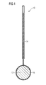
- FIG 1 illustrates a schematic cross-sectional view of as gasket 10 according to a preferred embodiment of the present invention.
- the gasket 10 is elongated, wherein the longitudinal axis of said gasket 10 extends perpendicular to the plane of the drawing in FIG 1 .
- the gasket 10 comprises a first gasket part 12, a second gasket part 14 and an interconnecting gasket part 16.
- the first gasket part 12, the second gasket part 14 and the interconnecting gasket part 16 are also elongated.
- the longitudinal axes of the first gasket part 12, the second gasket part 14 and the interconnecting gasket part 16 extend in parallel to each other.
- the gasket 10 is composed by the first gasket part 12, the second gasket part 14 and the interconnecting gasket part 16 and forms an integral part.
- the first gasket part 12 has a circular cross-section.
- the first gasket part 12 is resistant against high temperatures. Further, the first gasket part 12 is thermally insulating. Moreover, the first gasket part 12 is impermeable for vapour, steam and humidity.
- the first gasket part 12 is transparent to microwaves.
- the interconnecting gasket part 16 connects the first gasket part 12 and the second gasket part 14.
- the interconnecting gasket part 16 is made of one or more flexible sheets. In this example, a central portion of the cross-section of the interconnecting gasket part 16 encloses the first gasket part 12, while both end portions of the cross-section of the interconnecting gasket part 16 are received by the second gasket part 14.
- the second gasket part 14 has a U-shaped cross-section, wherein the end portions of the cross-section of the interconnecting gasket part 16 are received between the legs of said U-shaped cross-section.
- the second gasket part 14 forms a U-shaped profile part.
- the legs of the U-shaped profile part are relative long in view of the width of said U-shaped profile part.
- the second gasket part 14 is also resistant against high temperatures. Furthermore, the second gasket part 14 cannot be penetrated by microwaves.
- the second gasket part 14 is also thermally insulating and impermeable for vapour, steam and humidity.
- the first gasket part 12 blocks heat and is impermeable for vapour, steam and humidity, but transparent to microwaves.
- the first gasket part 12 is made of material including technical textiles.
- said technical textiles base on glass fibres.
- the first gasket part 12 is made of an elastic material or by an elastic compound of materials.
- a gap of variable size can be sealed by the first gasket part 12 made of elastic material.
- said variable size of the gap may be caused by tolerances of production.
- the first gasket part 12 with the elastic material allows the required seal effect along the sealing line of the gasket 10.
- the second gasket part 14 is made of at least one heat temperature resistant material.
- the second gasket part 14 blocks heat and is impermeable for vapour, steam and humidity. Additionally, the second gasket part 14 cannot be penetrated by microwaves.
- the second gasket part 14 or at least an outer layer of said second gasket part 14 includes metallic material or materials.
- the metallic material includes technical textiles.
- said technical textiles base on metallized glass fibres.
- the technical textiles or the fibres may be coated by electrically conductive material.
- the glass fibres may be connected with fibres of electrically conductive material, preferably metallic material.
- the glass fibres may be interwoven with fibres of electrically conductive material, preferably metallic material.
- the second gasket part may include small metallic particles equally distributed within said second gasket part.
- the second gasket part may include at least one metal grid.
- the second gasket part 14 can be connected form-fit and/or force-fit to the surrounding receptacle area of the appliance.
- the gasket 10 blocks humidity, vapour, liquids, steam and/or heat by the first gasket part 12 and the second gasket part 14. Additionally, the gasket 10 shows microwave blockage by the second gasket part 14.
- the gasket 10 is provided for sealing of closed heat-charged cavities of appliance with microwave heating function.
- the gasket 10 may be used for all appliances for domestic and professional use with microwave heating function.
- the gasket 10 is suitable for washing machines, laundry dryers and dish-washers, wherein at least one drying process of dishes, laundry and/or the cavity itself is improved by microwave heating.
- the gasket 10 is also suitable for appliances, wherein the process time is reduced by microwave heating.
- the gasket 10 is suitable for appliances, wherein other functions of said appliances are improved by microwave heating.
- the gasket 10 can be used for appliances, wherein sterilization is performed by microwave heating.
- the gasket 10 may be provided for sealing two independent gaps.
- said gaps are adjacent to each other.
- the cross-section of the gaps may be arranged orthogonal or serial to each other.
- the gasket 10 may be provided for sealing one single gap.
- the first gasket part 12 may be provided for a gap formed between a door at the one side and the cavity and/or a front frame on the other side. More general, the first gasket part 12 may be provided for a gap variable by the action of the user. Such a gap needs to be sealed against dirt, vapour, moist and/or steam. However, said gap must not form a microwave barrier. The microwave barrier in said gap would excessively heat up the first gasket part 12.
- the second gasket part 14 is provided for a gap formed between the cavity and the front frame of the appliance. More general, the second gasket part 14 is provided for a gap formed between an inner chassis part and an outer chassis part of the appliance.
- Such kind of gap is predetermined by the construction of the appliance, but does not depend on the action of the user. Usually, such a gap forms a thermal barrier. A microwave barrier is required in said gap.
Landscapes
- Engineering & Computer Science (AREA)
- General Engineering & Computer Science (AREA)
- Mechanical Engineering (AREA)
- Physics & Mathematics (AREA)
- Electromagnetism (AREA)
- Chemical & Material Sciences (AREA)
- Combustion & Propulsion (AREA)
- Gasket Seals (AREA)
- Constitution Of High-Frequency Heating (AREA)
- Electric Ovens (AREA)
- Cookers (AREA)
Abstract
Description
- The present invention relates to a gasket for a heat-charged cavity of an appliance with microwave heating function. Further, the present invention relates to an appliance with microwave heating function for domestic or professional use, wherein the appliance includes at least one heat-charged cavity enclosed by at least one gap.
- In the near future, further innovative appliances with microwave heating function are expected. For example, dish-washers, washing machines, freezers with a fast defrosting system and laundry dryers may be heated up by microwaves. The removal of excess liquids, vapours and/or humidity from the heated cavity of the appliance may be improved by the microwave heating function.
- Such an appliance requires a sealing of the gaps around the heated cavity. Usually the sealing is realized by one or more gaskets. Said gaskets must be heat resistant and impermeable for liquids, vapours, humidity and/or heat. However, within some types of gaps a microwave transparency is necessary, while other types of gaps should be sealed against microwaves.
- It is an object of the present invention to provide an improved gasket for an appliance with microwave heating function, wherein the properties of the gasket are adapted to the requirements of said appliance by low complexity.
- The object is achieved by the gasket according to claim 1.
- According to the present invention the gasket is provided for a heat-charged cavity of an appliance with microwave heating function, wherein
- the gasket comprises a first gasket part, a second gasket part and an interconnecting gasket part,
- the first gasket part, the second gasket part and the interconnecting gasket part are elongated and their longitudinal axes are arranged parallel to each other,
- the first gasket part and the second gasket part are impermeable for steam, vapour and/or humidity,
- the first gasket part is made of an elastic material or a compound of elastic materials and is resistant against high temperatures,
- the second gasket part is resistant against high temperatures and includes at least one electrically conductive material,
- the interconnecting gasket part is resistant against high temperatures,
- the interconnecting gasket part is permanently or removably connected to the first gasket part at one side and to the second gasket part at another side of said interconnecting gasket part, and
- the gasket is formed as an integral part.
- The first gasket part and the second gasket part of the gasket have different functions. The first gasket part as well as the second gasket part is heat resistant and impermeable for steam, vapour and/or humidity. However, the first gasket part is made of an elastic material or a compound of elastic materials, while the second gasket part includes at least one electrically conductive material. Thus, the first gasket part is transparent to microwaves, while the second gasket part cannot be penetrated by microwaves.
- In particular, the interconnecting gasket part includes at least one flexible sheet.
- Preferably, the at least one flexible sheet of the interconnecting gasket part encloses at least partially the first gasket part.
- Further, the at least one flexible sheet of the interconnecting gasket part is partially received by the second gasket part.
- According to the preferred embodiment of the present invention, the second gasket part includes a U-shaped cross-section. Thus, the second gasket part forms a U-shaped profile part.
- In particular, the at least one flexible sheet of the interconnecting gasket part is partially received by the legs of the U-shaped cross-section of the second gasket part.
- The first gasket part, the second gasket part and/or the interconnecting gasket part may be made of technical textiles, preferably on the basis of glass fibres.
- For example, the second gasket part includes glass fibres coated by at least one electrically conductive material, preferably metallic material.
- According to another example, the second gasket part includes glass fibres interwoven with fibres made of at least one electrically conductive material, preferably metallic material.
- Alternatively or additionally, the second gasket part may include small metallic particles equally distributed within said second gasket part.
- Furthermore, the second gasket part includes at least one metal grid.
- The present invention relates further to an appliance with microwave heating function for domestic or professional use, wherein the appliance includes at least one heat-charged cavity enclosed by at least one gap, wherein the at least one gap is at least partially filled by a gasket mentioned above.
- Preferably, the appliance comprises at least two adjacent gaps, wherein a first gap is at least partially filled by the first gasket part and a second gap is at least partially filled by the second gasket part.
- In particular, the first gap is arranged between a door at one side and an inner chassis part and/or outer chassis part of the appliance at another side, wherein said first gap occurs in a closed state of the door. Thereby, the inner chassis part may be the cavity, while the outer chassis part may be a front frame.
- In contrast, the second gap may be arranged between an inner chassis part and an outer chassis part of the appliance, in particular the second gap is arranged between the cavity and the front frame, wherein the second gap forms a thermal barrier.
- For example, the cross-sections of the first gap and the second gap are arranged orthogonal to each other.
- Alternatively or additionally, the cross-sections of the first gap and the second gap may be arranged serially to each other.
- Novel and inventive features of the present invention are set forth in the appended claims.
- The present invention will be described in further detail with reference to the drawing, in which
- FIG 1
- illustrates a schematic cross-sectional view of as gasket according to a preferred embodiment of the present invention.
-
FIG 1 illustrates a schematic cross-sectional view of asgasket 10 according to a preferred embodiment of the present invention. Thegasket 10 is elongated, wherein the longitudinal axis of saidgasket 10 extends perpendicular to the plane of the drawing inFIG 1 . - The
gasket 10 comprises afirst gasket part 12, asecond gasket part 14 and an interconnectinggasket part 16. Thefirst gasket part 12, thesecond gasket part 14 and the interconnectinggasket part 16 are also elongated. The longitudinal axes of thefirst gasket part 12, thesecond gasket part 14 and the interconnectinggasket part 16 extend in parallel to each other. Thegasket 10 is composed by thefirst gasket part 12, thesecond gasket part 14 and the interconnectinggasket part 16 and forms an integral part. - In this example, the
first gasket part 12 has a circular cross-section. Thefirst gasket part 12 is resistant against high temperatures. Further, thefirst gasket part 12 is thermally insulating. Moreover, thefirst gasket part 12 is impermeable for vapour, steam and humidity. Thefirst gasket part 12 is transparent to microwaves. - The interconnecting
gasket part 16 connects thefirst gasket part 12 and thesecond gasket part 14. The interconnectinggasket part 16 is made of one or more flexible sheets. In this example, a central portion of the cross-section of the interconnectinggasket part 16 encloses thefirst gasket part 12, while both end portions of the cross-section of the interconnectinggasket part 16 are received by thesecond gasket part 14. - In this example, the
second gasket part 14 has a U-shaped cross-section, wherein the end portions of the cross-section of the interconnectinggasket part 16 are received between the legs of said U-shaped cross-section. In other words, thesecond gasket part 14 forms a U-shaped profile part. In this example, the legs of the U-shaped profile part are relative long in view of the width of said U-shaped profile part. Thesecond gasket part 14 is also resistant against high temperatures. Furthermore, thesecond gasket part 14 cannot be penetrated by microwaves. Thesecond gasket part 14 is also thermally insulating and impermeable for vapour, steam and humidity. - The
first gasket part 12 blocks heat and is impermeable for vapour, steam and humidity, but transparent to microwaves. Preferably, thefirst gasket part 12 is made of material including technical textiles. In particular, said technical textiles base on glass fibres. Thefirst gasket part 12 is made of an elastic material or by an elastic compound of materials. A gap of variable size can be sealed by thefirst gasket part 12 made of elastic material. For example, said variable size of the gap may be caused by tolerances of production. Thefirst gasket part 12 with the elastic material allows the required seal effect along the sealing line of thegasket 10. - The
second gasket part 14 is made of at least one heat temperature resistant material. Thesecond gasket part 14 blocks heat and is impermeable for vapour, steam and humidity. Additionally, thesecond gasket part 14 cannot be penetrated by microwaves. Thesecond gasket part 14 or at least an outer layer of saidsecond gasket part 14 includes metallic material or materials. Preferably, the metallic material includes technical textiles. For example, said technical textiles base on metallized glass fibres. The technical textiles or the fibres may be coated by electrically conductive material. Further, the glass fibres may be connected with fibres of electrically conductive material, preferably metallic material. For example, the glass fibres may be interwoven with fibres of electrically conductive material, preferably metallic material. Alternatively or additionally, the second gasket part may include small metallic particles equally distributed within said second gasket part. Furthermore, the second gasket part may include at least one metal grid. Thesecond gasket part 14 can be connected form-fit and/or force-fit to the surrounding receptacle area of the appliance. - The
gasket 10 blocks humidity, vapour, liquids, steam and/or heat by thefirst gasket part 12 and thesecond gasket part 14. Additionally, thegasket 10 shows microwave blockage by thesecond gasket part 14. - In particular, the
gasket 10 is provided for sealing of closed heat-charged cavities of appliance with microwave heating function. Thegasket 10 may be used for all appliances for domestic and professional use with microwave heating function. Further, thegasket 10 is suitable for washing machines, laundry dryers and dish-washers, wherein at least one drying process of dishes, laundry and/or the cavity itself is improved by microwave heating. Thegasket 10 is also suitable for appliances, wherein the process time is reduced by microwave heating. Moreover, thegasket 10 is suitable for appliances, wherein other functions of said appliances are improved by microwave heating. For example, thegasket 10 can be used for appliances, wherein sterilization is performed by microwave heating. - The
gasket 10 may be provided for sealing two independent gaps. In particular, said gaps are adjacent to each other. The cross-section of the gaps may be arranged orthogonal or serial to each other. Further, thegasket 10 may be provided for sealing one single gap. - For example, the
first gasket part 12 may be provided for a gap formed between a door at the one side and the cavity and/or a front frame on the other side. More general, thefirst gasket part 12 may be provided for a gap variable by the action of the user. Such a gap needs to be sealed against dirt, vapour, moist and/or steam. However, said gap must not form a microwave barrier. The microwave barrier in said gap would excessively heat up thefirst gasket part 12. - For example, the
second gasket part 14 is provided for a gap formed between the cavity and the front frame of the appliance. More general, thesecond gasket part 14 is provided for a gap formed between an inner chassis part and an outer chassis part of the appliance. Such kind of gap is predetermined by the construction of the appliance, but does not depend on the action of the user. Usually, such a gap forms a thermal barrier. A microwave barrier is required in said gap. - Although an illustrative embodiment of the present invention has been described herein with reference to the accompanying drawing, it is to be understood that the present invention is not limited to that precise embodiment, and that various other changes and modifications may be affected therein by one skilled in the art without departing from the scope or spirit of the invention. All such changes and modifications are intended to be included within the scope of the invention as defined by the appended claims.
-
- 10
- gasket
- 12
- first gasket part
- 14
- second gasket part
- 16
- interconnecting gasket part
Claims (15)
- A gasket (10) for a heat-charged cavity of an appliance with microwave heating function, wherein- the gasket (12) comprises a first gasket part (12), a second gasket part (14) and an interconnecting gasket part (16),- the first gasket part (12), the second gasket part (14) and the interconnecting gasket part (16) are elongated and their longitudinal axes are arranged parallel to each other,- the first gasket part (12) and the second gasket part (14) are impermeable for steam, vapour and/or humidity,- the first gasket part (12) is made of an elastic material or a compound of elastic materials and is resistant against high temperatures,- the second gasket part (14) is resistant against high temperatures and includes at least one electrically conductive material,- the interconnecting gasket part (16) is resistant against high temperatures,- the interconnecting gasket part (16) is permanently or removably connected to the first gasket part (12) at one side and to the second gasket part (14) at another side of said interconnecting gasket part (16), and- the gasket (12) is formed as an integral part.
- The gasket (10) according to claim 1,
characterized in that
the interconnecting gasket part (16) includes at least one flexible sheet. - The gasket (10) according to claim 2,
characterized in that
the at least one flexible sheet of the interconnecting gasket part (16) encloses at least partially the first gasket part (12) and/or is partially received by the second gasket part (14). - The gasket (10) according to claim 2,
characterized in that
the second gasket part (14) includes a U-shaped cross-section, wherein the at least one flexible sheet of the interconnecting gasket part (16) is partially received by the legs of the U-shaped cross-section of the second gasket part (14). - The gasket (10) according to any one of the preceding claims,
characterized in that
the first gasket part (12), the second gasket part (14) and/or the interconnecting gasket part (16) are made of technical textiles, preferably on the basis of glass fibres. - The gasket (10) according to any one of the preceding claims,
characterized in that
the second gasket part (14) includes glass fibres coated by at least one electrically conductive material, preferably metallic material. - The gasket (10) according to any one of the preceding claims,
characterized in that
the second gasket part (14) includes glass fibres interwoven with fibres made of at least one electrically conductive material, preferably metallic material. - The gasket (10) according to any one of the preceding claims,
characterized in that
the second gasket part (14) includes small metallic particles equally distributed within said second gasket part (14). - The gasket (10) according to any one of the preceding claims,
characterized in that
the second gasket part (14) includes at least one metal grid. - An appliance with microwave heating function for domestic or professional use, wherein the appliance includes at least one heat-charged cavity enclosed by at least one gap, characterized in that
the at least one gap is at least partially filled by a gasket (10) according to any one of the claims 1 to 9. - The appliance according to claim 10,
characterized in that
the appliance comprises at least two adjacent gaps, wherein a first gap is at least partially filled by the first gasket part (12) and a second gap is at least partially filled by the second gasket part (14). - The appliance according to claim 11,
characterized in that
the first gap is arranged between a door at one side and the cavity and/or a front frame at another side, wherein said first gap occurs in a closed state of the door. - The appliance according to claim 11 or 12,
characterized in that
the second gap is arranged between an inner chassis part and an outer chassis part of the appliance, in particular the second gap is arranged between the cavity and the front frame, wherein the second gap forms a thermal barrier. - The appliance according to any one of the claims 11 to 13,
characterized in that
the cross-sections of the first gap and the second gap are arranged orthogonal to each other. - The appliance according to any one of the claims 11 to 14,
characterized in that
the cross-sections of the first gap and the second gap are arranged serially to each other.
Priority Applications (6)
| Application Number | Priority Date | Filing Date | Title |
|---|---|---|---|
| EP14179025.3A EP2866519B1 (en) | 2013-10-23 | 2014-07-30 | A gasket for a heat-charged cavity of an appliance with microwave heating function |
| AU2014339165A AU2014339165B2 (en) | 2013-10-23 | 2014-10-13 | A gasket for a heat-charged cavity of an appliance with microwave heating function |
| CN201480052134.6A CN105557067A (en) | 2013-10-23 | 2014-10-13 | A gasket for a heat-charged cavity of an appliance with microwave heating function |
| BR112016008985-5A BR112016008985B1 (en) | 2013-10-23 | 2014-10-13 | GASKET FOR A THERMALLY LOADED CAVITY OF AN APPLIANCE WITH MICROWAVE HEATING FUNCTION AND APPLIANCE WITH MICROWAVE HEATING FUNCTION |
| PCT/EP2014/071869 WO2015058989A1 (en) | 2013-10-23 | 2014-10-13 | A gasket for a heat-charged cavity of an appliance with microwave heating function |
| US14/915,391 US20160219657A1 (en) | 2013-10-23 | 2014-10-13 | Gasket for a heat-charged cavity of an appliance with microwave heating function |
Applications Claiming Priority (3)
| Application Number | Priority Date | Filing Date | Title |
|---|---|---|---|
| PCT/EP2013/072149 WO2014114371A1 (en) | 2013-01-25 | 2013-10-23 | A microwave oven or a multifunctional oven with microwave heating function |
| PCT/EP2014/051487 WO2014114783A1 (en) | 2013-01-25 | 2014-01-27 | A gasket adapted for a microwave oven or a cooking oven with microwave heating function and a microwave oven or a cooking oven with microwave heating function comprising the same |
| EP14179025.3A EP2866519B1 (en) | 2013-10-23 | 2014-07-30 | A gasket for a heat-charged cavity of an appliance with microwave heating function |
Publications (2)
| Publication Number | Publication Date |
|---|---|
| EP2866519A1 true EP2866519A1 (en) | 2015-04-29 |
| EP2866519B1 EP2866519B1 (en) | 2016-11-30 |
Family
ID=51260636
Family Applications (1)
| Application Number | Title | Priority Date | Filing Date |
|---|---|---|---|
| EP14179025.3A Not-in-force EP2866519B1 (en) | 2013-10-23 | 2014-07-30 | A gasket for a heat-charged cavity of an appliance with microwave heating function |
Country Status (6)
| Country | Link |
|---|---|
| US (1) | US20160219657A1 (en) |
| EP (1) | EP2866519B1 (en) |
| CN (1) | CN105557067A (en) |
| AU (1) | AU2014339165B2 (en) |
| BR (1) | BR112016008985B1 (en) |
| WO (1) | WO2015058989A1 (en) |
Cited By (1)
| Publication number | Priority date | Publication date | Assignee | Title |
|---|---|---|---|---|
| EP3139097A3 (en) * | 2015-09-02 | 2017-05-03 | Lg Electronics Inc. | Cooker with gasket |
Citations (4)
| Publication number | Priority date | Publication date | Assignee | Title |
|---|---|---|---|---|
| GB1351457A (en) * | 1970-03-20 | 1974-05-01 | Tibbs C E M | Electrical heating devices |
| US3846608A (en) * | 1974-02-11 | 1974-11-05 | Litton Systems Inc | High temperature resistant door seal for a microwave oven |
| US4512331A (en) * | 1984-05-24 | 1985-04-23 | The Maytag Company | Oven seal arrangement |
| WO2009156613A1 (en) * | 2008-06-02 | 2009-12-30 | Federal Mogul Systems Protection | Seal, furnace part provided with such a seal, and furnace including such a seal |
Family Cites Families (5)
| Publication number | Priority date | Publication date | Assignee | Title |
|---|---|---|---|---|
| US2219962A (en) * | 1939-09-18 | 1940-10-29 | Reynolds Edward Bert | Gasket |
| US3812316A (en) * | 1973-03-28 | 1974-05-21 | Gen Electric | Door seal gasket for combined microwave and self-cleaning oven |
| US4081647A (en) * | 1976-05-10 | 1978-03-28 | Roper Corporation | Energy seal for a microwave oven |
| US5066028A (en) * | 1989-05-30 | 1991-11-19 | Davlyn Manufacturing Co. | Gasket assembly |
| FR2896677B1 (en) * | 2006-02-01 | 2010-08-20 | Seb Sa | COOKING APPARATUS WITH MEANS OF REMUTING AND METHOD THEREOF |
-
2014
- 2014-07-30 EP EP14179025.3A patent/EP2866519B1/en not_active Not-in-force
- 2014-10-13 CN CN201480052134.6A patent/CN105557067A/en active Pending
- 2014-10-13 AU AU2014339165A patent/AU2014339165B2/en not_active Ceased
- 2014-10-13 US US14/915,391 patent/US20160219657A1/en not_active Abandoned
- 2014-10-13 WO PCT/EP2014/071869 patent/WO2015058989A1/en not_active Ceased
- 2014-10-13 BR BR112016008985-5A patent/BR112016008985B1/en not_active IP Right Cessation
Patent Citations (4)
| Publication number | Priority date | Publication date | Assignee | Title |
|---|---|---|---|---|
| GB1351457A (en) * | 1970-03-20 | 1974-05-01 | Tibbs C E M | Electrical heating devices |
| US3846608A (en) * | 1974-02-11 | 1974-11-05 | Litton Systems Inc | High temperature resistant door seal for a microwave oven |
| US4512331A (en) * | 1984-05-24 | 1985-04-23 | The Maytag Company | Oven seal arrangement |
| WO2009156613A1 (en) * | 2008-06-02 | 2009-12-30 | Federal Mogul Systems Protection | Seal, furnace part provided with such a seal, and furnace including such a seal |
Cited By (3)
| Publication number | Priority date | Publication date | Assignee | Title |
|---|---|---|---|---|
| EP3139097A3 (en) * | 2015-09-02 | 2017-05-03 | Lg Electronics Inc. | Cooker with gasket |
| US10376098B2 (en) | 2015-09-02 | 2019-08-13 | Lg Electronics Inc. | Cooker with gasket |
| US11045045B2 (en) | 2015-09-02 | 2021-06-29 | Lg Electronics Inc. | Cooker with gasket |
Also Published As
| Publication number | Publication date |
|---|---|
| US20160219657A1 (en) | 2016-07-28 |
| CN105557067A (en) | 2016-05-04 |
| EP2866519B1 (en) | 2016-11-30 |
| BR112016008985B1 (en) | 2022-05-31 |
| AU2014339165B2 (en) | 2018-09-20 |
| BR112016008985A2 (en) | 2017-08-01 |
| AU2014339165A1 (en) | 2016-03-10 |
| WO2015058989A1 (en) | 2015-04-30 |
Similar Documents
| Publication | Publication Date | Title |
|---|---|---|
| EP2949179B1 (en) | An oven door and a chassis for a microwave oven or an appliance with microwave heating function | |
| EP1890085A2 (en) | Cooking oven with anti-condensation door | |
| US20100308034A1 (en) | Microwave oven door with a waves chokes system | |
| CA2461794C (en) | Methods and apparatus for operating a speedcooking oven | |
| AU2014339165B2 (en) | A gasket for a heat-charged cavity of an appliance with microwave heating function | |
| EP2815629B1 (en) | A microwave oven or a multifunctional oven with microwave heating function | |
| US10690391B2 (en) | Appliance using heated glass panels | |
| US20210348768A1 (en) | Sealing system for an oven cavity | |
| US9016270B2 (en) | Window mounting for thermal expansion in an oven appliance | |
| CN202908542U (en) | Electric oven | |
| WO2015096865A1 (en) | Door for use in a household appliance and household appliance having the same | |
| KR102207470B1 (en) | Oven | |
| CN110753413A (en) | Enclosed door, microwave oven, oven and dryer | |
| CN203841532U (en) | Door seal structure of electric steamer or oven | |
| EP3340739B1 (en) | Oven door for a microwave oven | |
| KR100697417B1 (en) | Oven Cavity Temperature Sensor | |
| CN210493774U (en) | cooking appliances | |
| CN201533777U (en) | Cooking heating appliance | |
| ITTO20100615A1 (en) | INSULATED GLASS DOOR, PERFECTLY FOR REFRIGERANT APPLIANCES. | |
| WO2019129440A1 (en) | Profile assembly and electrical connections in a transparent cooker | |
| KR20130139005A (en) | Cooker | |
| EP1260771A1 (en) | Cooking oven with anti-condensation ventilation apertures | |
| KR20120079358A (en) | Heater unit and cooking appliance comprising the same |
Legal Events
| Date | Code | Title | Description |
|---|---|---|---|
| PUAI | Public reference made under article 153(3) epc to a published international application that has entered the european phase |
Free format text: ORIGINAL CODE: 0009012 |
|
| 17P | Request for examination filed |
Effective date: 20140730 |
|
| AK | Designated contracting states |
Kind code of ref document: A1 Designated state(s): AL AT BE BG CH CY CZ DE DK EE ES FI FR GB GR HR HU IE IS IT LI LT LU LV MC MK MT NL NO PL PT RO RS SE SI SK SM TR |
|
| AX | Request for extension of the european patent |
Extension state: BA ME |
|
| RBV | Designated contracting states (corrected) |
Designated state(s): AL AT BE BG CH CY CZ DE DK EE ES FI FR GB GR HR HU IE IS IT LI LT LU LV MC MK MT NL NO PL PT RO RS SE SI SK SM TR |
|
| R17P | Request for examination filed (corrected) |
Effective date: 20151028 |
|
| GRAP | Despatch of communication of intention to grant a patent |
Free format text: ORIGINAL CODE: EPIDOSNIGR1 |
|
| RIC1 | Information provided on ipc code assigned before grant |
Ipc: F24C 15/02 20060101ALI20160622BHEP Ipc: H05B 6/76 20060101AFI20160622BHEP |
|
| INTG | Intention to grant announced |
Effective date: 20160714 |
|
| GRAS | Grant fee paid |
Free format text: ORIGINAL CODE: EPIDOSNIGR3 |
|
| GRAA | (expected) grant |
Free format text: ORIGINAL CODE: 0009210 |
|
| AK | Designated contracting states |
Kind code of ref document: B1 Designated state(s): AL AT BE BG CH CY CZ DE DK EE ES FI FR GB GR HR HU IE IS IT LI LT LU LV MC MK MT NL NO PL PT RO RS SE SI SK SM TR |
|
| REG | Reference to a national code |
Ref country code: CH Ref legal event code: EP Ref country code: GB Ref legal event code: FG4D |
|
| REG | Reference to a national code |
Ref country code: AT Ref legal event code: REF Ref document number: 850863 Country of ref document: AT Kind code of ref document: T Effective date: 20161215 |
|
| REG | Reference to a national code |
Ref country code: IE Ref legal event code: FG4D |
|
| REG | Reference to a national code |
Ref country code: DE Ref legal event code: R096 Ref document number: 602014005144 Country of ref document: DE |
|
| PG25 | Lapsed in a contracting state [announced via postgrant information from national office to epo] |
Ref country code: LV Free format text: LAPSE BECAUSE OF FAILURE TO SUBMIT A TRANSLATION OF THE DESCRIPTION OR TO PAY THE FEE WITHIN THE PRESCRIBED TIME-LIMIT Effective date: 20161130 |
|
| REG | Reference to a national code |
Ref country code: LT Ref legal event code: MG4D |
|
| REG | Reference to a national code |
Ref country code: NL Ref legal event code: MP Effective date: 20161130 |
|
| REG | Reference to a national code |
Ref country code: AT Ref legal event code: MK05 Ref document number: 850863 Country of ref document: AT Kind code of ref document: T Effective date: 20161130 |
|
| PG25 | Lapsed in a contracting state [announced via postgrant information from national office to epo] |
Ref country code: GR Free format text: LAPSE BECAUSE OF FAILURE TO SUBMIT A TRANSLATION OF THE DESCRIPTION OR TO PAY THE FEE WITHIN THE PRESCRIBED TIME-LIMIT Effective date: 20170301 Ref country code: LT Free format text: LAPSE BECAUSE OF FAILURE TO SUBMIT A TRANSLATION OF THE DESCRIPTION OR TO PAY THE FEE WITHIN THE PRESCRIBED TIME-LIMIT Effective date: 20161130 Ref country code: SE Free format text: LAPSE BECAUSE OF FAILURE TO SUBMIT A TRANSLATION OF THE DESCRIPTION OR TO PAY THE FEE WITHIN THE PRESCRIBED TIME-LIMIT Effective date: 20161130 Ref country code: NO Free format text: LAPSE BECAUSE OF FAILURE TO SUBMIT A TRANSLATION OF THE DESCRIPTION OR TO PAY THE FEE WITHIN THE PRESCRIBED TIME-LIMIT Effective date: 20170228 |
|
| PG25 | Lapsed in a contracting state [announced via postgrant information from national office to epo] |
Ref country code: FI Free format text: LAPSE BECAUSE OF FAILURE TO SUBMIT A TRANSLATION OF THE DESCRIPTION OR TO PAY THE FEE WITHIN THE PRESCRIBED TIME-LIMIT Effective date: 20161130 Ref country code: HR Free format text: LAPSE BECAUSE OF FAILURE TO SUBMIT A TRANSLATION OF THE DESCRIPTION OR TO PAY THE FEE WITHIN THE PRESCRIBED TIME-LIMIT Effective date: 20161130 Ref country code: AT Free format text: LAPSE BECAUSE OF FAILURE TO SUBMIT A TRANSLATION OF THE DESCRIPTION OR TO PAY THE FEE WITHIN THE PRESCRIBED TIME-LIMIT Effective date: 20161130 Ref country code: PT Free format text: LAPSE BECAUSE OF FAILURE TO SUBMIT A TRANSLATION OF THE DESCRIPTION OR TO PAY THE FEE WITHIN THE PRESCRIBED TIME-LIMIT Effective date: 20170330 Ref country code: RS Free format text: LAPSE BECAUSE OF FAILURE TO SUBMIT A TRANSLATION OF THE DESCRIPTION OR TO PAY THE FEE WITHIN THE PRESCRIBED TIME-LIMIT Effective date: 20161130 Ref country code: PL Free format text: LAPSE BECAUSE OF FAILURE TO SUBMIT A TRANSLATION OF THE DESCRIPTION OR TO PAY THE FEE WITHIN THE PRESCRIBED TIME-LIMIT Effective date: 20161130 Ref country code: ES Free format text: LAPSE BECAUSE OF FAILURE TO SUBMIT A TRANSLATION OF THE DESCRIPTION OR TO PAY THE FEE WITHIN THE PRESCRIBED TIME-LIMIT Effective date: 20161130 |
|
| PG25 | Lapsed in a contracting state [announced via postgrant information from national office to epo] |
Ref country code: NL Free format text: LAPSE BECAUSE OF FAILURE TO SUBMIT A TRANSLATION OF THE DESCRIPTION OR TO PAY THE FEE WITHIN THE PRESCRIBED TIME-LIMIT Effective date: 20161130 |
|
| PG25 | Lapsed in a contracting state [announced via postgrant information from national office to epo] |
Ref country code: EE Free format text: LAPSE BECAUSE OF FAILURE TO SUBMIT A TRANSLATION OF THE DESCRIPTION OR TO PAY THE FEE WITHIN THE PRESCRIBED TIME-LIMIT Effective date: 20161130 Ref country code: SK Free format text: LAPSE BECAUSE OF FAILURE TO SUBMIT A TRANSLATION OF THE DESCRIPTION OR TO PAY THE FEE WITHIN THE PRESCRIBED TIME-LIMIT Effective date: 20161130 Ref country code: RO Free format text: LAPSE BECAUSE OF FAILURE TO SUBMIT A TRANSLATION OF THE DESCRIPTION OR TO PAY THE FEE WITHIN THE PRESCRIBED TIME-LIMIT Effective date: 20161130 Ref country code: DK Free format text: LAPSE BECAUSE OF FAILURE TO SUBMIT A TRANSLATION OF THE DESCRIPTION OR TO PAY THE FEE WITHIN THE PRESCRIBED TIME-LIMIT Effective date: 20161130 Ref country code: CZ Free format text: LAPSE BECAUSE OF FAILURE TO SUBMIT A TRANSLATION OF THE DESCRIPTION OR TO PAY THE FEE WITHIN THE PRESCRIBED TIME-LIMIT Effective date: 20161130 |
|
| PG25 | Lapsed in a contracting state [announced via postgrant information from national office to epo] |
Ref country code: SM Free format text: LAPSE BECAUSE OF FAILURE TO SUBMIT A TRANSLATION OF THE DESCRIPTION OR TO PAY THE FEE WITHIN THE PRESCRIBED TIME-LIMIT Effective date: 20161130 Ref country code: BG Free format text: LAPSE BECAUSE OF FAILURE TO SUBMIT A TRANSLATION OF THE DESCRIPTION OR TO PAY THE FEE WITHIN THE PRESCRIBED TIME-LIMIT Effective date: 20170228 Ref country code: BE Free format text: LAPSE BECAUSE OF FAILURE TO SUBMIT A TRANSLATION OF THE DESCRIPTION OR TO PAY THE FEE WITHIN THE PRESCRIBED TIME-LIMIT Effective date: 20161130 |
|
| REG | Reference to a national code |
Ref country code: DE Ref legal event code: R097 Ref document number: 602014005144 Country of ref document: DE |
|
| PLBE | No opposition filed within time limit |
Free format text: ORIGINAL CODE: 0009261 |
|
| STAA | Information on the status of an ep patent application or granted ep patent |
Free format text: STATUS: NO OPPOSITION FILED WITHIN TIME LIMIT |
|
| 26N | No opposition filed |
Effective date: 20170831 |
|
| PG25 | Lapsed in a contracting state [announced via postgrant information from national office to epo] |
Ref country code: SI Free format text: LAPSE BECAUSE OF FAILURE TO SUBMIT A TRANSLATION OF THE DESCRIPTION OR TO PAY THE FEE WITHIN THE PRESCRIBED TIME-LIMIT Effective date: 20161130 |
|
| REG | Reference to a national code |
Ref country code: CH Ref legal event code: PL |
|
| REG | Reference to a national code |
Ref country code: FR Ref legal event code: ST Effective date: 20180330 |
|
| PG25 | Lapsed in a contracting state [announced via postgrant information from national office to epo] |
Ref country code: LI Free format text: LAPSE BECAUSE OF NON-PAYMENT OF DUE FEES Effective date: 20170731 Ref country code: CH Free format text: LAPSE BECAUSE OF NON-PAYMENT OF DUE FEES Effective date: 20170731 |
|
| REG | Reference to a national code |
Ref country code: IE Ref legal event code: MM4A |
|
| PG25 | Lapsed in a contracting state [announced via postgrant information from national office to epo] |
Ref country code: FR Free format text: LAPSE BECAUSE OF NON-PAYMENT OF DUE FEES Effective date: 20170731 |
|
| PG25 | Lapsed in a contracting state [announced via postgrant information from national office to epo] |
Ref country code: LU Free format text: LAPSE BECAUSE OF NON-PAYMENT OF DUE FEES Effective date: 20170730 |
|
| PG25 | Lapsed in a contracting state [announced via postgrant information from national office to epo] |
Ref country code: IE Free format text: LAPSE BECAUSE OF NON-PAYMENT OF DUE FEES Effective date: 20170730 |
|
| PG25 | Lapsed in a contracting state [announced via postgrant information from national office to epo] |
Ref country code: MT Free format text: LAPSE BECAUSE OF NON-PAYMENT OF DUE FEES Effective date: 20170730 |
|
| GBPC | Gb: european patent ceased through non-payment of renewal fee |
Effective date: 20180730 |
|
| PG25 | Lapsed in a contracting state [announced via postgrant information from national office to epo] |
Ref country code: GB Free format text: LAPSE BECAUSE OF NON-PAYMENT OF DUE FEES Effective date: 20180730 |
|
| PG25 | Lapsed in a contracting state [announced via postgrant information from national office to epo] |
Ref country code: MC Free format text: LAPSE BECAUSE OF FAILURE TO SUBMIT A TRANSLATION OF THE DESCRIPTION OR TO PAY THE FEE WITHIN THE PRESCRIBED TIME-LIMIT Effective date: 20161130 Ref country code: HU Free format text: LAPSE BECAUSE OF FAILURE TO SUBMIT A TRANSLATION OF THE DESCRIPTION OR TO PAY THE FEE WITHIN THE PRESCRIBED TIME-LIMIT; INVALID AB INITIO Effective date: 20140730 |
|
| PG25 | Lapsed in a contracting state [announced via postgrant information from national office to epo] |
Ref country code: CY Free format text: LAPSE BECAUSE OF FAILURE TO SUBMIT A TRANSLATION OF THE DESCRIPTION OR TO PAY THE FEE WITHIN THE PRESCRIBED TIME-LIMIT Effective date: 20161130 |
|
| PG25 | Lapsed in a contracting state [announced via postgrant information from national office to epo] |
Ref country code: MK Free format text: LAPSE BECAUSE OF FAILURE TO SUBMIT A TRANSLATION OF THE DESCRIPTION OR TO PAY THE FEE WITHIN THE PRESCRIBED TIME-LIMIT Effective date: 20161130 |
|
| PG25 | Lapsed in a contracting state [announced via postgrant information from national office to epo] |
Ref country code: TR Free format text: LAPSE BECAUSE OF FAILURE TO SUBMIT A TRANSLATION OF THE DESCRIPTION OR TO PAY THE FEE WITHIN THE PRESCRIBED TIME-LIMIT Effective date: 20161130 |
|
| PG25 | Lapsed in a contracting state [announced via postgrant information from national office to epo] |
Ref country code: AL Free format text: LAPSE BECAUSE OF FAILURE TO SUBMIT A TRANSLATION OF THE DESCRIPTION OR TO PAY THE FEE WITHIN THE PRESCRIBED TIME-LIMIT Effective date: 20161130 Ref country code: IS Free format text: LAPSE BECAUSE OF FAILURE TO SUBMIT A TRANSLATION OF THE DESCRIPTION OR TO PAY THE FEE WITHIN THE PRESCRIBED TIME-LIMIT Effective date: 20170330 |
|
| PGFP | Annual fee paid to national office [announced via postgrant information from national office to epo] |
Ref country code: IT Payment date: 20220726 Year of fee payment: 9 Ref country code: DE Payment date: 20220720 Year of fee payment: 9 |
|
| P01 | Opt-out of the competence of the unified patent court (upc) registered |
Effective date: 20230625 |
|
| REG | Reference to a national code |
Ref country code: DE Ref legal event code: R119 Ref document number: 602014005144 Country of ref document: DE |
|
| PG25 | Lapsed in a contracting state [announced via postgrant information from national office to epo] |
Ref country code: DE Free format text: LAPSE BECAUSE OF NON-PAYMENT OF DUE FEES Effective date: 20240201 |
|
| PG25 | Lapsed in a contracting state [announced via postgrant information from national office to epo] |
Ref country code: IT Free format text: LAPSE BECAUSE OF NON-PAYMENT OF DUE FEES Effective date: 20230730 |