EP2866491B1 - Slow MAC-E for autonomous transmission in high speed uplink packet access (HSUPA) along with service specific transmission time control - Google Patents
Slow MAC-E for autonomous transmission in high speed uplink packet access (HSUPA) along with service specific transmission time control Download PDFInfo
- Publication number
- EP2866491B1 EP2866491B1 EP14197908.8A EP14197908A EP2866491B1 EP 2866491 B1 EP2866491 B1 EP 2866491B1 EP 14197908 A EP14197908 A EP 14197908A EP 2866491 B1 EP2866491 B1 EP 2866491B1
- Authority
- EP
- European Patent Office
- Prior art keywords
- mac
- transmission
- tti
- packet
- packets
- Prior art date
- Legal status (The legal status is an assumption and is not a legal conclusion. Google has not performed a legal analysis and makes no representation as to the accuracy of the status listed.)
- Revoked
Links
- 230000005540 biological transmission Effects 0.000 title claims description 90
- 238000000034 method Methods 0.000 claims description 49
- 230000001965 increasing effect Effects 0.000 claims description 8
- 238000012545 processing Methods 0.000 claims description 6
- 239000000872 buffer Substances 0.000 description 11
- 230000011664 signaling Effects 0.000 description 8
- 230000008901 benefit Effects 0.000 description 5
- 238000010586 diagram Methods 0.000 description 5
- 238000004891 communication Methods 0.000 description 4
- 230000003111 delayed effect Effects 0.000 description 4
- 101000665442 Homo sapiens Serine/threonine-protein kinase TBK1 Proteins 0.000 description 2
- 102100038192 Serine/threonine-protein kinase TBK1 Human genes 0.000 description 2
- 238000007796 conventional method Methods 0.000 description 2
- 230000001360 synchronised effect Effects 0.000 description 2
- 208000037918 transfusion-transmitted disease Diseases 0.000 description 2
- 101000741965 Homo sapiens Inactive tyrosine-protein kinase PRAG1 Proteins 0.000 description 1
- 102100038659 Inactive tyrosine-protein kinase PRAG1 Human genes 0.000 description 1
- 230000003044 adaptive effect Effects 0.000 description 1
- 238000013459 approach Methods 0.000 description 1
- 230000001413 cellular effect Effects 0.000 description 1
- 230000001419 dependent effect Effects 0.000 description 1
- 238000011161 development Methods 0.000 description 1
- 230000008030 elimination Effects 0.000 description 1
- 238000003379 elimination reaction Methods 0.000 description 1
- 238000005516 engineering process Methods 0.000 description 1
- 230000002708 enhancing effect Effects 0.000 description 1
- 238000013507 mapping Methods 0.000 description 1
- 238000005259 measurement Methods 0.000 description 1
- 238000005457 optimization Methods 0.000 description 1
- 230000002441 reversible effect Effects 0.000 description 1
- 238000006467 substitution reaction Methods 0.000 description 1
- 238000012546 transfer Methods 0.000 description 1
Images

Classifications
-
- H—ELECTRICITY
- H04—ELECTRIC COMMUNICATION TECHNIQUE
- H04J—MULTIPLEX COMMUNICATION
- H04J3/00—Time-division multiplex systems
- H04J3/16—Time-division multiplex systems in which the time allocation to individual channels within a transmission cycle is variable, e.g. to accommodate varying complexity of signals, to vary number of channels transmitted
-
- H—ELECTRICITY
- H04—ELECTRIC COMMUNICATION TECHNIQUE
- H04L—TRANSMISSION OF DIGITAL INFORMATION, e.g. TELEGRAPHIC COMMUNICATION
- H04L1/00—Arrangements for detecting or preventing errors in the information received
- H04L1/12—Arrangements for detecting or preventing errors in the information received by using return channel
- H04L1/16—Arrangements for detecting or preventing errors in the information received by using return channel in which the return channel carries supervisory signals, e.g. repetition request signals
- H04L1/18—Automatic repetition systems, e.g. Van Duuren systems
- H04L1/1812—Hybrid protocols; Hybrid automatic repeat request [HARQ]
-
- H—ELECTRICITY
- H04—ELECTRIC COMMUNICATION TECHNIQUE
- H04L—TRANSMISSION OF DIGITAL INFORMATION, e.g. TELEGRAPHIC COMMUNICATION
- H04L1/00—Arrangements for detecting or preventing errors in the information received
- H04L1/12—Arrangements for detecting or preventing errors in the information received by using return channel
- H04L1/16—Arrangements for detecting or preventing errors in the information received by using return channel in which the return channel carries supervisory signals, e.g. repetition request signals
- H04L1/18—Automatic repetition systems, e.g. Van Duuren systems
- H04L1/1867—Arrangements specially adapted for the transmitter end
- H04L1/1887—Scheduling and prioritising arrangements
-
- H—ELECTRICITY
- H04—ELECTRIC COMMUNICATION TECHNIQUE
- H04W—WIRELESS COMMUNICATION NETWORKS
- H04W28/00—Network traffic management; Network resource management
- H04W28/02—Traffic management, e.g. flow control or congestion control
-
- H—ELECTRICITY
- H04—ELECTRIC COMMUNICATION TECHNIQUE
- H04W—WIRELESS COMMUNICATION NETWORKS
- H04W80/00—Wireless network protocols or protocol adaptations to wireless operation
- H04W80/02—Data link layer protocols
Definitions
- the invention is related to the 3 rd Generation Partnership Project (3GPP) radio access network (RAN) standards, high speed uplink packet access (HSUPA) and high speed downlink packet access (HSDPA), and 3GPP Core Network and Speech Codecs and, more particularly, to a system and methods for slow medium access control entity (MAC-e) for autonomous transmission during HSUPA, an for service specific transmission time control in HSUPA.
- 3GPP 3rd Generation Partnership Project
- RAN radio access network
- HSUPA high speed uplink packet access
- HSDPA high speed downlink packet access
- MAC-e slow medium access control entity
- the Third Generation Partnership Project (3GPP) Technical Specification (TS) 25.309, "Frequency Division Duplex (FDD) Enhanced Uplink; Overall description; Stage 2 TS” has established that some level of enhanced dedicated channel (E-DCH) minimum set support is required to provide backward system compatibility.
- E-DCH enhanced dedicated channel
- a minimum set autonomous transmission of data packets can occur in an uplink signal without prior allocation of resources by a base station (i.e., Node B) scheduler.
- the minimum set defines a set of transport formats (TFs) for which a valid scheduling grant is not required in order for packets to be transmitted.
- the Node B allocates a share of an uplink resource to the UE via a scheduling grant. Only after this allocation of resources occurs is it possible for the UE to transmit packets in the uplink signal.
- the defined minimum set always guarantees a minimum bit rate, which is typically used for signaling purposes.
- the possibility for non-scheduled UEs to autonomously transmit a set of TFs has implications on Node B processing resources, because Node Bs must be continuously ready to process transmissions made from all such UEs, irrespective of the number of UEs that actually perform an autonomous transmission.
- the ability of the Node Bs to optimize the use of available Node B processing resources via scheduling becomes limited. Consequently, the complexity of the Node B for processing a given number of TFs may become increased.
- RoT RoT over Thermal
- TTI transmission time interval
- MAC-e medium access control entity
- PDU protocol data unit
- n non-scheduled UEs the worst case combined data rate in the cell due to autonomous transmission is n * 45 kb/sec for a fixed total number of retransmissions of 4.
- an assumption is made that the 45 kb/sec rate is achieved by transmitting at 180 kb/sec four times, at a reduced power level.
- the required RoT margin may become significant, which would then degrade the performance of the scheduled transmissions.
- the R1-041069 specification “Signaling Radio Bearer (SRB) Mapping, E-DCH Minimum Set and Node B Complexity Issues", developed by Motorola, Inc., includes proposed solutions to the foregoing problems, such as restricting the scenarios in which the minimum set applies to cases where, for example, there is no dedicated physical data channel (DPDCH).
- DPDCH dedicated physical data channel
- the technique disclosed uses a TDM based solution, where autonomous transmissions are only allowed in a subset of TTIs.
- E-DCH enhanced dedicated channels
- a grant is required, i.e., a non-scheduled grant is required for non-scheduled medium access control dedicated (MAC-d) flows and a serving grant is required for a scheduled transmission.
- the Node B controls when the UE is allowed to transmit packets and the maximum enhanced dedicated physical data channel (E-DPDCH) to dedicated physical control channel (DPCCH) power ratio that the UE is allowed to use for scheduled data in the following transmission.
- E-DPDCH enhanced dedicated physical data channel
- DPCCH dedicated physical control channel
- the network is permitted to define a maximum number of bits that can be included in a MAC-e PDU for specific MAC-d flows.
- each non-scheduled grant is applicable for the specific set of HARQ processes indicated by radio resource control (RRC), where the RRC can also restrict the set of HARQ processes for which scheduled grants are applicable.
- RRC radio resource control
- the data mapped on non-scheduled MAC-d flows is transmitted as soon as possible by the possible HARQ process restrictions and the possible available power restrictions, with the rate defined by the non-scheduled grant.
- the Universal Telecommunication Radio Access Network is limited in its ability to control the uplink (UL) transmission interval on an E-DCH.
- the UTRAN can select the TTI to be either 2 ms or 10 ms, when 2 ms TTI is supported by the UE.
- the UTRAN can define the permitted processes for scheduled MAC-d flows and non-scheduled MAC-d flows.
- BTS base transceiver station
- the transmission of a low bit rate service over E-DCH introduces the requirement for large control overhead due to several control channels in the uplink (UL) and the downlink (DL), and because the amount of control bits per TTI is the same for all packet sizes.
- an acknowledge/non-acknowledge (ACK/NACK) is transmitted in the DL and the enhanced transport format combination indicator (E-TFCI), in a robust secure network (RSN), and a 'Happy bit' is transmitted in the UL. It is possible to reduce the control overhead by transmitting more packets in the same transport block but less often. However, the payload in the TB and the TTI would be increased.
- the UTRAN could increase the transmission interval for specific services (e.g. voice over Internet protocol (VoIP)) in the UTRAN in order to increase transmission capacity.
- VoIP voice over Internet protocol
- the UTRAN should take into account the characteristics of the service, e.g. an assumed or known bit rate, delay requirement, possibly known service data unit (SDU) arrival rates, etc, when defining the transmission interval.
- SDU service data unit
- the service tolerates some additional delay in the radio interface.
- the packets could be sent once in every 40 or 60 ms in order to improve transmission capacity.
- the additional transmission delay of 20 to 40 ms has an unnoticeable impact in the speech quality.
- US 2004/160914 A1 discloses a congestion control method in which transmission rate is controlled with busy signal.
- the present invention relates to a method at a user equipment for slow medium access control (MAC) entity autonomous uplink transmission according to appended claim 1. Preferred embodiments of this method are defined in the dependent claims.
- MAC medium access control
- the present invention relates to enhancing the uplink discrete channel (E-DCH) for packet data traffic during Third Generation Partnership Project (3GPP) High Speed Uplink Packet Access (HSUPA), the 3FPP TR 25.808, specification "frequency division duplex (FDD) Enhanced Uplink; Physical Layer Aspects " and during the 3GPP TS 25.309, “Frequency Division Duplex (FDD) Enhanced Uplink; Overall description; Stage 2 ".
- E-DCH uplink discrete channel
- HSUPA High Speed Uplink Packet Access
- a check is made to determine whether the transmission is autonomous. If the transmission is not autonomous, a check is continually performed until an autonomous transmission occurs. That is, a continuous loop is performed. If an autonomous transmission is detected, then the exchange rate between the MAC-e and the physical layer (layer one) is slowed down, i.e. the exchange rate is decelerated. In accordance with the present invention, the slow down of the exchange rate between the MAC-e and the physical layer occurs when the MAC-e layer, i.e., the sub-layer of Layer Two sends a MAC-e PDU to the Layer One (i.e., the physical layer). The MAC-e PDU is sent to the physical layer every n * TTI, instead of once every transmission time interval (TTI).
- TTI transmission time interval
- the rate at which the MAC-e sends protocol data units (PDUs) to the physical layer for the transport format (TF(s)) belonging to a minimum set may be decelerated so as to reduce the impact of the minimum set over a "Rise over Thermal" (RoT).
- the minimum set defines a set of transport formats (TFs) for which a valid scheduling grant is not required in order for packets to be transmitted.
- a Node B i.e., a base station
- n As the value of n is increased, the effective bit rate and the impact of the autonomous transmission on the RoT become smaller. Synchronous HARQ may be used. As a result, it becomes possible to always use the same hybrid automatic repeat request (HARQ) process if n is selected as a multiple of the number of HARQ processes. In addition, different HARQ processes can be used based on a different value of n.
- the value of n may be selected by specification, signaled to UEs (i.e., a common value is signaled to the UEs) or UE dependant (i.e., a specific value that is signaled to a specific UE).
- the method of the invention is advantageously simpler than conventional methods for performing scheduling grants for scheduled transmissions.
- the present invention may be transparent to Layer One, and provide a minimum impact on Layer Two.
- a new control parameter is implemented in either a packet data protocol (PDP) context/radio access bearer (RAB) layer or in the MAC layer.
- PDP packet data protocol
- RAB radio access bearer
- a new PDP context/ quality of signal (QoS) parameter is used.
- the new parameter is a "service data unit (SDU) inter-arrival rate" that establishes the minimum required time interval between consecutive SDUs that are transmitted on a specific RAB.
- the parameter is signaled in different interfaces than the existing PDP context/RAB QoS parameters.
- the application does not deliver SDUs to the MAC layer at a higher rate than the rate specified by the parameter. If the data source produces several packets within this time interval, the packets are grouped into a single SDU. Grouping the packets in the MAC layer provides the ability to obtain the benefits associated with optimizing the packet header overhead, such as more efficiently sharing the uplink power resource between packet data users.
- the new parameter is a "virtual TTI" that defines the minimum time interval between subsequent new transmissions for a MAC-d flow.
- a first transmission would be permitted only once, during the virtual TTI.
- the virtual TTI could be signaled to the UE by the radio network controller (RNC). The UE could then implement the virtual TTI in the MAC-d layer.
- RNC radio network controller
- the present invention relates to a system and methods for slow medium access control entity (MAC-e) for autonomous transmission in HSUPA, along with service specific transmission time control.
- MAC-e slow medium access control entity
- MAC-e slow medium access control entity
- a control parameter that is independent from the air interface transmission time interval (TTI), hybrid automatic repeat request (HARQ) processes or enhanced dedicated transport channel (E-DCH) scheduling is used.
- TTI air interface transmission time interval
- HARQ hybrid automatic repeat request
- E-DCH enhanced dedicated transport channel
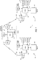
- FIG. 1 shows an exemplary network operator 2 having, for example, a mobile switching center (MSC) 3 for connecting to a telecommunications network, such as the Public Switched Telephone Network (PSTN), at least one base station controller (BSC) 4, and a plurality of base transceiver stations (BTS) 5 that transmit in a forward or downlink direction both physical and logical channels to the mobile stations 10 in accordance with a predetermined air interface standard.
- PSTN Public Switched Telephone Network
- BSC base station controller
- BTS base transceiver stations
- the BTSs 5 define cells, which can be different sizes, different frequencies and so forth.
- the air interface standard may conform to a Time Division Multiple Access (TDMA) air interface, and the network may be a Universal Mobile Telecommunications System (UMTS) network or other type of network.
- TDMA Time Division Multiple Access
- UMTS Universal Mobile Telecommunications System
- CDMA Code Division Multiple Access
- the network operator 2 can include a Message Service Center (MSCT) 6 that receives and forwards messages for the MS 10, such as Short Message Service (SMS) messages, or any wireless messaging technique including e-mail and Supplementary Data Services.
- SMS Short Message Service
- MMS Multimedia Messaging Service
- the mobile station (MS) 10 typically includes a micro-control unit (MCU) 12 having an output coupled to an input of a display 14 and an input coupled to an output of a keyboard or keypad 16.
- the MS 10 may be considered a handheld radiotelephone, such as a cellular, mobile telephone or a personal digital assistant (PDA), and may have a microphone and a speaker (not shown) for conducting voice communications.
- the MS 10 could also be contained within a card or module that is connected during use to another device.
- the MS 10 could be contained within a PCMCIA or similar type of card or module that is installed during use within a portable data processor, such as a laptop or notebook computer, or even a computer that is wearable by the user.
- the MCU 12 is assumed to include or be coupled to some type of a memory 13, including a read-only memory (ROM) for storing an operating program, as well as a random access memory (RAM) for temporarily storing required data, scratchpad memory, received data packets and data packets prepared for transmission, etc.
- ROM read-only memory
- RAM random access memory
- the memory 13 is assumed to store the various parameters that are used by the MS 10 for performing cell reselection.
- SIM storing, for example, a preferred Public Land Mobile Network (PLMN) list and other subscriber-related information.
- PLMN Public Land Mobile Network
- the ROM is assumed to store a program enabling the MCU 12 to execute the software routines required to operate in accordance with the preferred embodiments of the present invention.
- the MS 10 also contains a wireless section that includes a digital signal processor (DSP) 18, or equivalent high speed processor, as well as a wireless transceiver comprised of a transmitter 20 and a receiver 22, both of which are coupled to an antenna 24 for communication with the network operator 2.
- DSP digital signal processor
- the receiver 22 is used for making signal measurements used in the cell reselection process.
- packet schedulers are located in the Radio Network Controller (RNC) (not shown).
- RNC Radio Network Controller
- RRC Radio Resource
- UE user equipment
- the packet scheduler is limited in its ability to adapt to instantaneous traffic changes.
- the packet scheduler must conservatively allocate uplink power to take into account the influence from inactive users during a subsequent scheduling period.
- this solution is spectrally inefficient for high allocated data-rates and long-release timer values.
- the present invention utilizes the Node B (i.e., the base station) to handle the allocation of uplink resources, i.e. it performs Node B scheduling.
- the UE selects a transport channel combination (TFC) that is optimal for the amount of data to be transmitted in the radio link control (RLC) buffer of the UE in order to transmit data.
- TFC transport channel combination
- RLC radio link control
- the selection of the TFC is subject to constraints on the maximum transmission power of the UE and the maximum allowed TFC.
- the UE can request a higher bit rate, and the Node B will then decide whether to grant additional resources.
- the Node B may adjust the resources allocated to all UEs based on the current cell load.
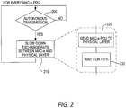
- FIG. 2 is an illustration of the steps associated with the method of the present invention. For every MAC-e PDU, a check is made to determine whether the transmission is autonomous, as indicated in step 200 . If the transmission is not autonomous, a check is continually performed until an autonomous transmission occurs, that is the method continues in a loop. If an autonomous transmission is detected, then the exchange rate between the MAC-e and the physical layer (layer one) is slowed down, i.e. the exchange rate is decelerated, as indicated in step 210 .
- the slow down of the exchange rate between the MAC-e and the physical layer occurs when the MAC-e layer, i.e., the sub-layer of Layer Two as described in the 3GPP IS 25.309 specification, "frequency division duplex (FDD) Enhanced Uplink; Overall description; Stage 2", sends a MAC-e PDU to the layer one (i.e., the physical layer), as indicated in step 220 .
- the MAC-e PDU is sent to the physical layer every n * TTI, instead of once every transmission time interval (TTI), as indicated in step 230 .
- the rate at which the MAC-e sends protocol data units (PDUs) to the physical layer for the transport format (TF(s)) belonging to a minimum set is decelerated so as to reduce the impact of the minimum set over a "Rise over Thermal" (RoT).
- the minimum set defines a set of transport formats (TFs) for which a valid scheduling grant is not required in order for packets to be transmitted.
- the Node B allocates a share of an uplink resource to the UE via a scheduling grant. From the perspective of layer one, the method of the invention is transparent, i.e., it appears that packets are only sent occasionally (e.g. once in a while).
- n As the value of n is increased, the effective bit rate and the impact of the autonomous transmission on the RoT become smaller.
- Synchronous HARQ as defined in the 3FPP TR 25.808, specification "frequency division duplex (FDD) Enhanced Uplink; Physical Layer Aspects " is used.
- FDD frequency division duplex
- Physical Layer Aspects As a result, it becomes possible to always use the same hybrid automatic repeat request (HARQ) process if n is selected as a multiple of the number of HARQ processes.
- different HARQ processes can be used based on a different value of n.
- n may be selected by specification, signaled to UEs (i.e., a common value is signaled to the UEs) or UE dependant (i.e., a specific value that is signaled to a specific UE).
- the method of the invention is advantageously simpler than conventional methods for performing scheduling grants for scheduled transmissions.
- the present invention is transparent to Layer One, and provides a minimum impact on Layer Two.
- the method of the invention is implemented as a new control parameter in either a packet data protocol (PDP) context/radio access bearer (RAB) layer or in the MAC layer.
- PDP packet data protocol
- RAB radio access bearer
- a new PDP context/ quality of signal (QoS) parameter is used.
- the new parameter is a "service data unit (SDU) inter-arrival rate" that establishes the minimum required time interval between consecutive SDUs that are transmitted on a specific RAB.
- the parameter is signaled in different interfaces than the existing PDP context/RAB QoS parameters.
- the application does not deliver SDUs to the MAC layer at a higher rate than the rate specified by the parameter. If the data source produces several packets within this time interval, the packets are grouped into a single SDU. Grouping the packets in the MAC layer provides the ability to obtain the benefits associated with optimizing the packet header overhead, such as more efficiently sharing the uplink power resource between packet data users.
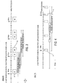
- FIGS. 3 and 4 are exemplary timing diagrams associated with the introduction of a packet data protocol (PDP) context/radio access bearer (RAB) Quality of Signal (QoS) parameter in the PDP context/RAB layer for a 10 ms and 2 ms air interface transmission time interval (TTI), respectively.
- PDP packet data protocol
- RAB radio access bearer
- QoS Quality of Signal
- 2 VoIP packets (i.e., 1 RLC SDU) are transmitted every 40 ms.
- a single VoIP packet is transmitted from the source every 20 ms. That is, the data source produces several (i.e. two) data packets within the 40 ms SDU inter-arrival rate that are grouped into the single SDU.
- One retransmission is shown for RLC SDUs #1 and #2, both containing 2 VoIP packets.
- the SDU inter-arrival rate of 40 ms ensures that the subsequent new RLC SDU #2 ( B ) will be transmitted after a delay of at least 40 ms after the RLC SDU #1 ( A ), and that the 2 VoIP packets produced by the source during the 40 ms period are grouped into single RLC SDU #2 ( B ). Due to retransmission (C) of the RLC SDU #1 ( A ), the delay for the first generated packet in the RLC SDU #1 (A) is 70 ms and the delay for the packet in the RLC SDU #1 ( A ) that is subsequently generated 20 ms later is 50 ms, i.e., both packets in the single RLC SDU are retransmitted.
- a packet refers to a VoIP packet from the source (e.g., voice codec) and the numbers with the boxes (A, B) refers to RLC SDU numbers. As shown in FIG.
- the delay for the first generated packet in the RLC SDU #1 (A) is 70 ms and the delay for the VoIP packet in the RLC SDU #1 (A) that is subsequently generated 20 ms later is 50 ms, i.e., both packets in the single RLC SDU are retransmitted 3 times.
- the preferred transmission interval would be an optimization for radio access network purposes and depends on, for example, the transport channel that is used. Consequently, the PDP context/RAB QoS parameter may not be the best place in which to define the transmission interval.
- the new parameter is a "virtual TTI" that defines the minimum time interval between subsequent new transmissions for a MAC-d flow.
- a first transmission would be permitted only once, during the virtual TTI.
- the virtual TTI could be signaled to the UE by the radio network controller (RNC). The UE could then implement the virtual TTI in the MAC-d layer.
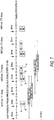
- VoIP packets are transmitted every 20 ms.
- a 40 ms virtual TTI in MAC-d 2 VoIP packets are transmitted in the same air interface TTI every 40 ms.
- a single packet is transmitted from the source every 20 ms and each RLC SDU contains one VoIP packet. That is, RLC SDUs, each containing a single VoIP packet, are delivered from the application to MAC every 20 ms.
- packets #1 ( A ) and packets #2 ( B ) are delivered to MAC layer in their own separate RLC SDUs with a 20 ms time difference, and grouped at MAC-d layer for transmittal in the same single 10 ms air interface TTI.
- the subsequent new packets #3 and #4 are grouped together in MAC-d for transmittal in the same 10 ms air interface TTI, because the 40 ms virtual TTI prevents this transmission before 40 ms after the start of the previous transmission has elapsed.
- the packets #1 ( A ) and #2 ( B ) are retransmitted ( C and D ).
- the packet #1 ( A ) is transmitted from the source 20 ms earlier than packet #2 (B), but is not allowed to be transmitted before the 40 ms virtual TTI has elapsed after the start of the previous packet first transmission.
- the delay for the packet #1 ( A ) with one retransmission ( C ) is 70 ms and the delay for the packet #2 ( B ) with one retransmission ( D ) is 50 ms.
- packet #3 ( A ) is delayed 80 ms and packet #4 ( B ) is delayed 60 ms, where the additional one air interface TTI (i.e., 10ms) delay, in comparison to packets #1 ( A ) and #2 ( B ) with the same number of retransmissions, is due to the retransmissions of the packets #1 ( A ) and #2 ( B ) occurring when the transmission of the packets #3 ( C ) and #4 ( D ) would first be allowed.
- TTI i.e. 10ms
- a packet refers to a VoIP packet from the source (e.g., voice codec) and the numbers with the boxes ( A, B , C , D ) refers to both packet and RLC SDU numbers.
- packets #1 ( A ) and #2 (B ) are transmitted in the same 2 ms air interface TTI and are retransmitted 3 times.
- the delay for packet #1 ( A ) is 70 ms and the delay for packet #2 ( B ) is 50 ms.
- the first transmission for the packet #1 (A) is allowed only 40 ms later than the previous packet first transmission and is thus, delayed an additional 20 ms in comparison to packet #2 ( B ) that can be transmitted without additional delay.
- the packets #3 ( C ) and #4 ( D ) are transmitted at the 40 ms virtual TTI later than the first transmission of the packets #1 ( A ) and #2 ( B ).
- Defining the parameter in the MAC layer advantageously supports the elimination of the dependency on the radio access network, as compared to the case where the transmission interval is defined in the PDP context/RAB parameter. If several radio bearers (RB) are multiplexed into the same transport channel, it should be possible to separately define a "virtual TTI" for each RB.
- the RNC uses the parameters delivered by the serving general packet radio service (GPRS) support node (SGSN) to identify the specific services.
- GPRS general packet radio service
- SGSN serving general packet radio service support node
- the control i.e., the calculated delay
- the QoS values such as "source statistics descriptor” (SSD), "traffic class”, and "transfer delay” can be used to calculate the delay.
- SSD source statistics descriptor
- traffic class traffic class
- transfer delay can be used to calculate the delay.
- the virtual TTI is determined to be 40 ms.
- the load in the radio access network can be included as another criterion for determining the most optimal virtual TTI length.
- the lower the load level the shorter the virtual TTI that is used.
- the present invention is not to be limited to the examples based on the QoS and the like, i.e., the general approach regarding RNC algorithms in 3GPP. It is to be appreciated that other specific implementations are possible, which are based on specific RNC algorithms as required be each specific implementation.
- the invention is implemented in a high speed downlink shared transport channel (HS-DSCH).
- HS-DSCH high speed downlink shared transport channel
- the RAB attribute 'SDU inter-arrival rate' in the DL would permit the UTRAN to optimize its DL resources.
- the UTRAN is permitted to determine whether to use a 'virtual TTI' in the DL in the MAC layer.
- the advantage of signaling the 'virtual TTI' to the UE in the DL is that the UE can switch the receiver off during the inter-arrival period, even though it is possible to provide this functionality in the DL without signaling it to the UE.
- an alternative periodicity parameter T can be used to define the HS-SCCH decoding period instead of the HS-DSCH decoding period.
- the radio network controller (RNC) and base station (i.e., Node B), as defined in the current 3GPP specified network are exemplary. Therefore, the present invention is not to be limited to such a device. Rather, the present invention may be implemented in other packet switched (PS) networks, e.g., in an evolved 3GPP network depending on their frame structure and flexibility of the structure.
- PS packet switched
- the UE decides whether to use a 40 ms virtual TTI when it detects that the underlying RAN network is HSUPA. i.e., signalling of the parameters (i.e., the transmission interval) is not performed by the network, but is implemented internally in the UE.
- the UE may decide to use the 40 ms virtual TTI when it detects that the underlying RAN network is HSUPA.
- the virtual TTI is signalled by the network, and used on the MAC level as describe above.
- the information pertaining to the virtual TTI is conveyed to a unit that controls the packetization of packets from the data source into SDUs, for example, packetization of speech frames (in real-time transport protocol (RTP) payload).
- RTP real-time transport protocol
- based on the length of the virtual TTI it is possible to modify the packetizing rules so as to optimise the speech connection to the virtual TTI. For example, in the default operation, one 20 ms speech frame is placed into one user datagram protocol/real-time transport protocol/Internet protocol (UDP/RTP/IP) packet.
- UDP/RTP/IP user datagram protocol/real-time transport protocol/Internet protocol
- the virtual TTI is known to have a length of 40 ms, it is possible to insert two 20 ms frames into one UDP/RTP/IP packet and thus, reduce the UDP/RTP/IP protocol overhead and processing load in UE and the network.
- a single speech packet per radio link control (RLC) service data unit (SDU) or UDP/RTP/IP packet potentially provides a greater level of flexibility than embodiments in which several speech packets are combined into one RTP/UDP/IP packet.
- RLC radio link control
- SDU radio link control
- UDP/RTP/IP packet potentially provides a greater level of flexibility than embodiments in which several speech packets are combined into one RTP/UDP/IP packet.
- HSDPA highspeed download packet access
- each speech packet in separate RLC SDUs permits the sending of only one speech packet per air interface TTI of 2 ms or 10 ms.
- RLC radio link control
- SRB signalling radio bearer
- the UE power limitations in bad radio conditions such as the UE running out of transmission power, are taken into account so that it then becomes possible to send a single speech packet per air interface TTI of 2 ms or 10 ms.
- the MAC-d would check the RLC buffer of the UE once per virtual TTI, i.e., at the same interval as a normal TTI as defined in the 3GPP IS 25.309 specification. As a result, packets received during the virtual TTI would be buffered at the RLC level.
- the MAC is permitted to check the RLC buffer more frequently in certain special cases, such as when it is not possible to clear the RLC buffer due to power limitations, the transmission of higher priority packets from other RLC buffer (e.g. SRB) or if there are bigger RLC SDUs (e.g., non-compressed headers or real time control protocol (RTCP) packets) that cannot be transmitted within one air interface TTI.
- RLC SDUs e.g., non-compressed headers or real time control protocol (RTCP) packets
- Examples of the operation of the UE MAC under such conditions are as follows: (i) if the MAC is able to empty the RLC buffer during this air interface TTI, then the MAC will check the RLC buffer at the next predetermined subsequent time interval after the virtual TTI; (ii) if the MAC is not able to empty the buffer, then the MAC will also check the RLC buffer for the next air interface TTI. This permits rapid clearing of the RLC buffers when required, i.e., when large SDUs are utilized. However, the frequency of transmissions during normal operation remains limited.
- the implementation of the present contemplated embodiment is permitted based on the configuration of the network, e.g., the network is configured to restrict the transmissions only to instances of times that are established by the virtual TTI or the network is configured to permit the above previously described operations.
- the transmission can be limited by controlling HARQ processes only up to every 16 ms, and in case of a 10 ms TTI up to 40 ms. It is also possible to control the TTI of scheduled transmissions by scheduling. However, this introduces large control overhead, i.e., two scheduled grants per single transmission occur.
- the present invention advantageously conserves control overhead. Specifically, the downlink E-DCH HARQ Indicator Channel (HICH) (i.e., the HARQ ACK/NAK is sent on E-HICH) overhead can be reduced because ACK/NAKs are needed less frequently. Also, the E-DCH dedicated physical control channel (E-DPCCH) overhead is reduced. In addition, a further savings in overhead is possible if the uplink dedicated physical control channel (UL DPCCH) gating is introduced. In this case, the DPCCH is not transmitted continuously but only when other UL channels are transmitted. In addition to the savings in system capacity, another advantage of the present invention is that battery power of the UE is conserved, since the UE needs to transmit and receive less often when a virtual TTI is used.
- HICH E-DCH HARQ Indicator Channel
- E-DPCCH E-DCH dedicated physical control channel
- UL DPCCH uplink dedicated physical control channel
- another advantage of the present invention is that battery power of the UE is conserve
Landscapes
- Engineering & Computer Science (AREA)
- Computer Networks & Wireless Communication (AREA)
- Signal Processing (AREA)
- Mobile Radio Communication Systems (AREA)
Description
- The invention is related to the 3rd Generation Partnership Project (3GPP) radio access network (RAN) standards, high speed uplink packet access (HSUPA) and high speed downlink packet access (HSDPA), and 3GPP Core Network and Speech Codecs and, more particularly, to a system and methods for slow medium access control entity (MAC-e) for autonomous transmission during HSUPA, an for service specific transmission time control in HSUPA.
- The Third Generation Partnership Project (3GPP) Technical Specification (TS) 25.309, "Frequency Division Duplex (FDD) Enhanced Uplink; Overall description;
Stage 2 TS" has established that some level of enhanced dedicated channel (E-DCH) minimum set support is required to provide backward system compatibility. With a minimum set, autonomous transmission of data packets can occur in an uplink signal without prior allocation of resources by a base station (i.e., Node B) scheduler. In other words, for each user equipment (UE), the minimum set defines a set of transport formats (TFs) for which a valid scheduling grant is not required in order for packets to be transmitted. In normal conditions, the Node B allocates a share of an uplink resource to the UE via a scheduling grant. Only after this allocation of resources occurs is it possible for the UE to transmit packets in the uplink signal. The defined minimum set always guarantees a minimum bit rate, which is typically used for signaling purposes. - From the perspective of the Node B scheduler, the possibility for non-scheduled UEs to autonomously transmit a set of TFs has implications on Node B processing resources, because Node Bs must be continuously ready to process transmissions made from all such UEs, irrespective of the number of UEs that actually perform an autonomous transmission. As a result, the ability of the Node Bs to optimize the use of available Node B processing resources via scheduling becomes limited. Consequently, the complexity of the Node B for processing a given number of TFs may become increased.
- The potential for a number of UEs to perform unscheduled autonomous transmissions may require the reservation of a "Rise over Thermal" (RoT) margin for these UEs. In the case of a 2 ms transmission time interval (TTI), a medium access control entity (MAC-e) protocol data unit (PDU) size of 360 bits, and n non-scheduled UEs, the worst case combined data rate in the cell due to autonomous transmission is n * 45 kb/sec for a fixed total number of retransmissions of 4. Here, an assumption is made that the 45 kb/sec rate is achieved by transmitting at 180 kb/sec four times, at a reduced power level. With a large number of UEs, the required RoT margin may become significant, which would then degrade the performance of the scheduled transmissions.
- The R1-041069 specification, "Signaling Radio Bearer (SRB) Mapping, E-DCH Minimum Set and Node B Complexity Issues", developed by Motorola, Inc., includes proposed solutions to the foregoing problems, such as restricting the scenarios in which the minimum set applies to cases where, for example, there is no dedicated physical data channel (DPDCH). In the R1-041087 specification, "Autonomous Transmission with Time Division Multiplex (TDM)", developed by Samsung, the technique disclosed uses a TDM based solution, where autonomous transmissions are only allowed in a subset of TTIs. Another solution proposed in the R1-041211 specification, "Support of Low Minimum Rate for E-DCH", developed by Lucent Technologies, involves increasing the permitted number of hybrid automatic repeat request (HARQ) transmissions for autonomous transmission rates, or restricting the number of HARQ processes that the UE is permitted to use for autonomous transmissions. However, each of these solutions is less than optimal because they all require a high level of complexity.
- The concept of enhanced dedicated channels (E-DCH) support was introduced in 3GPP Rel-6. For an E-DCH transmission, a grant is required, i.e., a non-scheduled grant is required for non-scheduled medium access control dedicated (MAC-d) flows and a serving grant is required for a scheduled transmission. For the scheduled MAC-d data flows, the Node B controls when the UE is allowed to transmit packets and the maximum enhanced dedicated physical data channel (E-DPDCH) to dedicated physical control channel (DPCCH) power ratio that the UE is allowed to use for scheduled data in the following transmission. For the non-scheduled MAC-d flows, the network is permitted to define a maximum number of bits that can be included in a MAC-e PDU for specific MAC-d flows.
- In the case of a 2 ms E-DCH TTI, each non-scheduled grant is applicable for the specific set of HARQ processes indicated by radio resource control (RRC), where the RRC can also restrict the set of HARQ processes for which scheduled grants are applicable. Here, the data mapped on non-scheduled MAC-d flows is transmitted as soon as possible by the possible HARQ process restrictions and the possible available power restrictions, with the rate defined by the non-scheduled grant.
- The Universal Telecommunication Radio Access Network (UTRAN) is limited in its ability to control the uplink (UL) transmission interval on an E-DCH. The UTRAN can select the TTI to be either 2 ms or 10 ms, when 2 ms TTI is supported by the UE. In the case of a 2 ms TTI, the UTRAN can define the permitted processes for scheduled MAC-d flows and non-scheduled MAC-d flows. Here, it is the base transceiver station (BTS) that decides the scheduling grants of scheduled transmission.
- The transmission of a low bit rate service over E-DCH introduces the requirement for large control overhead due to several control channels in the uplink (UL) and the downlink (DL), and because the amount of control bits per TTI is the same for all packet sizes. For example, for each transport block (TB) that is transmitted on an E-DCH, an acknowledge/non-acknowledge (ACK/NACK) is transmitted in the DL and the enhanced transport format combination indicator (E-TFCI), in a robust secure network (RSN), and a 'Happy bit' is transmitted in the UL. It is possible to reduce the control overhead by transmitting more packets in the same transport block but less often. However, the payload in the TB and the TTI would be increased.
- Preferably, the UTRAN could increase the transmission interval for specific services (e.g. voice over Internet protocol (VoIP)) in the UTRAN in order to increase transmission capacity. Here, the UTRAN should take into account the characteristics of the service, e.g. an assumed or known bit rate, delay requirement, possibly known service data unit (SDU) arrival rates, etc, when defining the transmission interval.
- For example, according to rules set forth in chapter 5.1.1. of TS 26.236, in the case of 3GPP adaptive multi-rate (AMR) and AMR-Wideband (WB) codecs in conversational voice over (VoIP) connections, there is one user datagram protocol/real-time transport protocol/Internet protocol (UDP/RTP/IP) packet per speech frame, i.e., one packet in 20 ms. On E-DCH, this leads to a rate of one transport block (TB) transmission per 20 ms because the current MAC specification requires the UE to maximize the throughput of the highest priority data. Speech is typically high priority and thus, MAC tries to send the speech packet as soon as possible when received from the higher layers. However, the service tolerates some additional delay in the radio interface. As a result, the packets could be sent once in every 40 or 60 ms in order to improve transmission capacity. Here, it is possible to assume the additional transmission delay of 20 to 40 ms has an unnoticeable impact in the speech quality.
-
US 2004/160914 A1 discloses a congestion control method in which transmission rate is controlled with busy signal. - The present invention relates to a method at a user equipment for slow medium access control (MAC) entity autonomous uplink transmission according to appended
claim 1. Preferred embodiments of this method are defined in the dependent claims. - The embodiments and/or examples of the following description which are not covered by the appended claims are considered as not being part of the present invention.
- The present invention relates to enhancing the uplink discrete channel (E-DCH) for packet data traffic during Third Generation Partnership Project (3GPP) High Speed Uplink Packet Access (HSUPA), the 3FPP TR 25.808, specification "frequency division duplex (FDD) Enhanced Uplink; Physical Layer Aspects" and during the 3GPP TS 25.309, "Frequency Division Duplex (FDD) Enhanced Uplink; Overall description; ".
- For every MAC-e PDU, a check is made to determine whether the transmission is autonomous. If the transmission is not autonomous, a check is continually performed until an autonomous transmission occurs. That is, a continuous loop is performed. If an autonomous transmission is detected, then the exchange rate between the MAC-e and the physical layer (layer one) is slowed down, i.e. the exchange rate is decelerated. In accordance with the present invention, the slow down of the exchange rate between the MAC-e and the physical layer occurs when the MAC-e layer, i.e., the sub-layer of Layer Two sends a MAC-e PDU to the Layer One (i.e., the physical layer). The MAC-e PDU is sent to the physical layer every n * TTI, instead of once every transmission time interval (TTI).
- The rate at which the MAC-e sends protocol data units (PDUs) to the physical layer for the transport format (TF(s)) belonging to a minimum set may be decelerated so as to reduce the impact of the minimum set over a "Rise over Thermal" (RoT). For each user equipment (UE), the minimum set defines a set of transport formats (TFs) for which a valid scheduling grant is not required in order for packets to be transmitted. In normal conditions, a Node B (i.e., a base station) allocates a share of an uplink resource to the UE via a scheduling grant. From the perspective of layer one, the method of the invention is transparent, i.e., it appears that packets are only sent occasionally (e.g. once in a while).
- As the value of n is increased, the effective bit rate and the impact of the autonomous transmission on the RoT become smaller. Synchronous HARQ may be used. As a result, it becomes possible to always use the same hybrid automatic repeat request (HARQ) process if n is selected as a multiple of the number of HARQ processes. In addition, different HARQ processes can be used based on a different value of n. Here, the value of n may be selected by specification, signaled to UEs (i.e., a common value is signaled to the UEs) or UE dependant (i.e., a specific value that is signaled to a specific UE). The method of the invention is advantageously simpler than conventional methods for performing scheduling grants for scheduled transmissions. Moreover, the present invention may be transparent to Layer One, and provide a minimum impact on Layer Two.
- In an embodiment of the invention, a new control parameter is implemented in either a packet data protocol (PDP) context/radio access bearer (RAB) layer or in the MAC layer. When the invention is implemented in the PDP context/radio access RAB layer, a new PDP context/ quality of signal (QoS) parameter is used. In the preferred embodiment, the new parameter is a "service data unit (SDU) inter-arrival rate" that establishes the minimum required time interval between consecutive SDUs that are transmitted on a specific RAB. In accordance with the present embodiment, the parameter is signaled in different interfaces than the existing PDP context/RAB QoS parameters. As a result, the application does not deliver SDUs to the MAC layer at a higher rate than the rate specified by the parameter. If the data source produces several packets within this time interval, the packets are grouped into a single SDU. Grouping the packets in the MAC layer provides the ability to obtain the benefits associated with optimizing the packet header overhead, such as more efficiently sharing the uplink power resource between packet data users.
- Alternatively, it is possible to introduce a new MAC parameter in the MAC-d layer. In the preferred embodiment, the new parameter is a "virtual TTI" that defines the minimum time interval between subsequent new transmissions for a MAC-d flow. A first transmission would be permitted only once, during the virtual TTI. The virtual TTI could be signaled to the UE by the radio network controller (RNC). The UE could then implement the virtual TTI in the MAC-d layer.
- Other objects and features of the present invention will become apparent from the following detailed description considered in conjunction with the accompanying drawings. It is to be understood, however, that the drawings are designed solely for purposes of illustration and not as a definition of the limits of the invention, for which reference should be made to the appended claims. It should be further understood that the drawings are merely intended to conceptually illustrate the structures and procedures described herein.
- The foregoing and other advantages and features of the invention will become more apparent from the detailed description of the preferred embodiments of the invention given below with reference to the accompanying drawing in which:
-
FIG. 1 is an exemplary block diagram of a wireless communication system in which the method of the invention is implemented; -
FIG. 2 is an exemplary flow chart illustrating the steps of the method of the invention; -
FIGS. 3 and 4 are exemplary timing diagrams associated with the introduction of a packet data protocol (PDP) context/ radio access bearer (RAB) Quality of Signal (QoS) parameter in the PDP context/RAB layer for a 10 ms and 2 ms transmission time interval (TTI), respectively; -
FIGS. 5 and 6 are exemplary timing diagrams associated with the introduction of a new medium access control (MAC) parameter can be introduced in the medium access control dedicated (MAC-d) layer for a 10 ms and 2 ms transmission time interval, respectively; and -
FIG. 7 is an exemplary timing diagram associated with the example ofFIG. 5 . - The present invention relates to a system and methods for slow medium access control entity (MAC-e) for autonomous transmission in HSUPA, along with service specific transmission time control. In accordance with the invention, a control parameter that is independent from the air interface transmission time interval (TTI), hybrid automatic repeat request (HARQ) processes or enhanced dedicated transport channel (E-DCH) scheduling is used. This control defines the minimum time interval between subsequent new transmissions. The control has no impact on retransmissions, which are performed normally.
-
FIG. 1 shows anexemplary network operator 2 having, for example, a mobile switching center (MSC) 3 for connecting to a telecommunications network, such as the Public Switched Telephone Network (PSTN), at least one base station controller (BSC) 4, and a plurality of base transceiver stations (BTS) 5 that transmit in a forward or downlink direction both physical and logical channels to themobile stations 10 in accordance with a predetermined air interface standard. It is assumed that a reverse or uplink communication path exists from themobile station 10 to the network operator, which conveys mobile originated access requests and traffic, as well as signaling for implementing the invention. TheBTSs 5 define cells, which can be different sizes, different frequencies and so forth. - The air interface standard may conform to a Time Division Multiple Access (TDMA) air interface, and the network may be a Universal Mobile Telecommunications System (UMTS) network or other type of network. However, the teachings of the present invention apply equally to Code Division Multiple Access (CDMA) networks, as well as to other network types.
- The
network operator 2 can include a Message Service Center (MSCT) 6 that receives and forwards messages for theMS 10, such as Short Message Service (SMS) messages, or any wireless messaging technique including e-mail and Supplementary Data Services. Furthermore, enhancements to SMS can be used, such as one under development and known as Multimedia Messaging Service (MMS), wherein image messages, video messages, audio messages, text messages, executables and the like, and combinations thereof, can be transferred between a network and a mobile station. - The mobile station (MS) 10 typically includes a micro-control unit (MCU) 12 having an output coupled to an input of a
display 14 and an input coupled to an output of a keyboard orkeypad 16. TheMS 10 may be considered a handheld radiotelephone, such as a cellular, mobile telephone or a personal digital assistant (PDA), and may have a microphone and a speaker (not shown) for conducting voice communications. TheMS 10 could also be contained within a card or module that is connected during use to another device. For example, theMS 10 could be contained within a PCMCIA or similar type of card or module that is installed during use within a portable data processor, such as a laptop or notebook computer, or even a computer that is wearable by the user. - The
MCU 12 is assumed to include or be coupled to some type of amemory 13, including a read-only memory (ROM) for storing an operating program, as well as a random access memory (RAM) for temporarily storing required data, scratchpad memory, received data packets and data packets prepared for transmission, etc. Thememory 13 is assumed to store the various parameters that are used by theMS 10 for performing cell reselection. - A separate, removable SIM (not shown) can be also be provided, the SIM storing, for example, a preferred Public Land Mobile Network (PLMN) list and other subscriber-related information. The ROM is assumed to store a program enabling the
MCU 12 to execute the software routines required to operate in accordance with the preferred embodiments of the present invention. - The
MS 10 also contains a wireless section that includes a digital signal processor (DSP) 18, or equivalent high speed processor, as well as a wireless transceiver comprised of atransmitter 20 and areceiver 22, both of which are coupled to anantenna 24 for communication with thenetwork operator 2. Thereceiver 22 is used for making signal measurements used in the cell reselection process. - In conventional system architectures, packet schedulers are located in the Radio Network Controller (RNC) (not shown). In addition, the Radio Resource (RRC) signaling interface between the RNC and the user equipment (UE) has bandwidth constraints. As a result, the packet scheduler is limited in its ability to adapt to instantaneous traffic changes. Hence, to accommodate this variation in network traffic, the packet scheduler must conservatively allocate uplink power to take into account the influence from inactive users during a subsequent scheduling period. However, this solution is spectrally inefficient for high allocated data-rates and long-release timer values.
- Along with enhanced dedicated channel (E-DCH), the present invention utilizes the Node B (i.e., the base station) to handle the allocation of uplink resources, i.e. it performs Node B scheduling. Here, the UE selects a transport channel combination (TFC) that is optimal for the amount of data to be transmitted in the radio link control (RLC) buffer of the UE in order to transmit data. However, the selection of the TFC is subject to constraints on the maximum transmission power of the UE and the maximum allowed TFC. However, if needed, the UE can request a higher bit rate, and the Node B will then decide whether to grant additional resources. In certain embodiments, the Node B may adjust the resources allocated to all UEs based on the current cell load.
-
FIG. 2 is an illustration of the steps associated with the method of the present invention. For every MAC-e PDU, a check is made to determine whether the transmission is autonomous, as indicated instep 200. If the transmission is not autonomous, a check is continually performed until an autonomous transmission occurs, that is the method continues in a loop. If an autonomous transmission is detected, then the exchange rate between the MAC-e and the physical layer (layer one) is slowed down, i.e. the exchange rate is decelerated, as indicated instep 210. In accordance with the invention, the slow down of the exchange rate between the MAC-e and the physical layer occurs when the MAC-e layer, i.e., the sub-layer of Layer Two as described in the 3GPP IS 25.309 specification, "frequency division duplex (FDD) Enhanced Uplink; Overall description;Stage 2", sends a MAC-e PDU to the layer one (i.e., the physical layer), as indicated instep 220. The MAC-e PDU is sent to the physical layer every n * TTI, instead of once every transmission time interval (TTI), as indicated instep 230. - Alternatively, the rate at which the MAC-e sends protocol data units (PDUs) to the physical layer for the transport format (TF(s)) belonging to a minimum set is decelerated so as to reduce the impact of the minimum set over a "Rise over Thermal" (RoT). For each user equipment (UE), the minimum set defines a set of transport formats (TFs) for which a valid scheduling grant is not required in order for packets to be transmitted. In normal conditions, the Node B allocates a share of an uplink resource to the UE via a scheduling grant. From the perspective of layer one, the method of the invention is transparent, i.e., it appears that packets are only sent occasionally (e.g. once in a while).
- As the value of n is increased, the effective bit rate and the impact of the autonomous transmission on the RoT become smaller. Synchronous HARQ as defined in the 3FPP TR 25.808, specification "frequency division duplex (FDD) Enhanced Uplink; Physical Layer Aspects " is used. As a result, it becomes possible to always use the same hybrid automatic repeat request (HARQ) process if n is selected as a multiple of the number of HARQ processes. In addition, different HARQ processes can be used based on a different value of n. Here, the value of n may be selected by specification, signaled to UEs (i.e., a common value is signaled to the UEs) or UE dependant (i.e., a specific value that is signaled to a specific UE). The method of the invention is advantageously simpler than conventional methods for performing scheduling grants for scheduled transmissions. Moreover, the present invention is transparent to Layer One, and provides a minimum impact on Layer Two.
- In an embodiment of the present invention, the method of the invention is implemented as a new control parameter in either a packet data protocol (PDP) context/radio access bearer (RAB) layer or in the MAC layer. When the invention is implemented in the PDP context/radio access RAB layer, a new PDP context/ quality of signal (QoS) parameter is used. In the preferred embodiment, the new parameter is a "service data unit (SDU) inter-arrival rate" that establishes the minimum required time interval between consecutive SDUs that are transmitted on a specific RAB. In accordance with the present embodiment, the parameter is signaled in different interfaces than the existing PDP context/RAB QoS parameters. As a result, the application does not deliver SDUs to the MAC layer at a higher rate than the rate specified by the parameter. If the data source produces several packets within this time interval, the packets are grouped into a single SDU. Grouping the packets in the MAC layer provides the ability to obtain the benefits associated with optimizing the packet header overhead, such as more efficiently sharing the uplink power resource between packet data users.
- When larger sized SDUs are used instead of more frequently transmitted smaller sized SDUs, it becomes possible to decrease the processing load in the UE, the core network and the radio access network. However, it may not always be possible to consider the SDU inter-arrival rate parameter and perform such a grouping within the application layer, depending on how transparent the radio network is to the application layer.
FIGS. 3 and 4 are exemplary timing diagrams associated with the introduction of a packet data protocol (PDP) context/radio access bearer (RAB) Quality of Signal (QoS) parameter in the PDP context/RAB layer for a 10 ms and 2 ms air interface transmission time interval (TTI), respectively. In each case, the SDU inter-arrival rate is 40 ms. - With reference to
FIG. 3 , for a 10 ms air interface TTI of 10 ms, 2 VoIP packets (i.e., 1 RLC SDU) are transmitted every 40 ms. In this case, a single VoIP packet is transmitted from the source every 20 ms. That is, the data source produces several (i.e. two) data packets within the 40 ms SDU inter-arrival rate that are grouped into the single SDU. One retransmission is shown forRLC SDUs # 1 and #2, both containing 2 VoIP packets. The SDU inter-arrival rate of 40 ms ensures that the subsequent new RLC SDU #2 (B) will be transmitted after a delay of at least 40 ms after the RLC SDU #1 (A), and that the 2 VoIP packets produced by the source during the 40 ms period are grouped into single RLC SDU #2 (B). Due to retransmission (C) of the RLC SDU #1 (A), the delay for the first generated packet in the RLC SDU #1 (A) is 70 ms and the delay for the packet in the RLC SDU #1 (A) that is subsequently generated 20 ms later is 50 ms, i.e., both packets in the single RLC SDU are retransmitted. Here, a retransmission of RLC SDU #2 (B) has also occurred. As a result, the 2 VoIP packets in B are delayed 80 ms and 60 ms, where the additional one air interface TTI (10ms) delay is due to the retransmission (C) of the RLC SDU #1 (A) occurring when the RLC SDU #2 (B) would first be allowed. In accordance with the contemplated embodiments, a packet refers to a VoIP packet from the source (e.g., voice codec) and the numbers with the boxes (A, B) refers to RLC SDU numbers. As shown inFIG. 4 for a 2 ms air interface TTI, there is no additional delay for the RLC SDU #2 (B) due to retransmissions of RLC SDU #1 (A), and the RLC SDU #2 (B) is transmitted 40 ms later than RLC SDU #1 (A) since the retransmissions RLC SDU #1 (A) occur in different HARQ processes than the transmission of RLC SDU #2 (B). Due to 3 retransmissions of the RLC SDU #1 (A), the delay for the first generated packet in the RLC SDU #1 (A) is 70 ms and the delay for the VoIP packet in the RLC SDU #1 (A) that is subsequently generated 20 ms later is 50 ms, i.e., both packets in the single RLC SDU are retransmitted 3 times. - The preferred transmission interval would be an optimization for radio access network purposes and depends on, for example, the transport channel that is used. Consequently, the PDP context/RAB QoS parameter may not be the best place in which to define the transmission interval. Alternatively, it is possible to introduce a new MAC parameter in the MAC-d layer. In the preferred embodiment, the new parameter is a "virtual TTI" that defines the minimum time interval between subsequent new transmissions for a MAC-d flow. A first transmission would be permitted only once, during the virtual TTI. The virtual TTI could be signaled to the UE by the radio network controller (RNC). The UE could then implement the virtual TTI in the MAC-d layer.
- With reference to
FIG. 5 , for a 10 ms air interface and a TTI of 10 ms, VoIP packets are transmitted every 20 ms. With a 40 ms virtual TTI in MAC-d, 2 VoIP packets are transmitted in the same air interface TTI every 40 ms. In this case, a single packet is transmitted from the source every 20 ms and each RLC SDU contains one VoIP packet. That is, RLC SDUs, each containing a single VoIP packet, are delivered from the application to MAC every 20 ms. Here, packets #1 (A) and packets #2 (B) are delivered to MAC layer in their own separate RLC SDUs with a 20 ms time difference, and grouped at MAC-d layer for transmittal in the same single 10 ms air interface TTI. - The subsequent
new packets # 3 and #4 are grouped together in MAC-d for transmittal in the same 10 ms air interface TTI, because the 40 ms virtual TTI prevents this transmission before 40 ms after the start of the previous transmission has elapsed. The packets #1 (A) and #2 (B) are retransmitted (C and D). The packet #1 (A) is transmitted from thesource 20 ms earlier than packet #2 (B), but is not allowed to be transmitted before the 40 ms virtual TTI has elapsed after the start of the previous packet first transmission. As a result, the delay for the packet #1 (A) with one retransmission (C) is 70 ms and the delay for the packet #2 (B) with one retransmission (D) is 50 ms. - Here, a retransmission of packets #1 (A) and #2 (B) has occurred. As a result, packet #3 (A) is delayed 80 ms and packet #4 (B) is delayed 60 ms, where the additional one air interface TTI (i.e., 10ms) delay, in comparison to packets #1 (A) and #2 (B) with the same number of retransmissions, is due to the retransmissions of the packets #1 (A) and #2 (B) occurring when the transmission of the packets #3 (C) and #4 (D) would first be allowed. In accordance with the contemplated embodiments, a packet refers to a VoIP packet from the source (e.g., voice codec) and the numbers with the boxes (A, B, C, D) refers to both packet and RLC SDU numbers.
- In
FIG. 6 , for a 2 ms air interface TTI, packets #1 (A) and #2 (B) are transmitted in the same 2 ms air interface TTI and are retransmitted 3 times. The delay for packet #1 (A) is 70 ms and the delay for packet #2 (B) is 50 ms. Here, the first transmission for the packet #1 (A) is allowed only 40 ms later than the previous packet first transmission and is thus, delayed an additional 20 ms in comparison to packet #2 (B) that can be transmitted without additional delay. The packets #3 (C) and #4 (D) are transmitted at the 40 ms virtual TTI later than the first transmission of the packets #1 (A) and #2 (B). - Additionally, it is possible to take into account the "virtual TTI" in the application layer to optimize the protocol header overhead, as discussed below. Defining the parameter in the MAC layer advantageously supports the elimination of the dependency on the radio access network, as compared to the case where the transmission interval is defined in the PDP context/RAB parameter. If several radio bearers (RB) are multiplexed into the same transport channel, it should be possible to separately define a "virtual TTI" for each RB.
- In the latter case, the RNC uses the parameters delivered by the serving general packet radio service (GPRS) support node (SGSN) to identify the specific services. It should be noted, however, the control (i.e., the calculated delay) is not based on the specific service, but rather the delay is based on the QoS parameters of the service. In addition, other available information can be used to determine the most optimal virtual TTI length. For example, the QoS values such as "source statistics descriptor" (SSD), "traffic class", and "transfer delay" can be used to calculate the delay. In certain embodiments, if SSD has value indicative of "speech" and the traffic class is conversational, then the virtual TTI is determined to be 40 ms. In addition, the load in the radio access network (RAN) can be included as another criterion for determining the most optimal virtual TTI length. In this case, the lower the load level, the shorter the virtual TTI that is used. The present invention is not to be limited to the examples based on the QoS and the like, i.e., the general approach regarding RNC algorithms in 3GPP. It is to be appreciated that other specific implementations are possible, which are based on specific RNC algorithms as required be each specific implementation.
- In the downlink direction (DL), the invention is implemented in a high speed downlink shared transport channel (HS-DSCH). Here, the RAB attribute 'SDU inter-arrival rate' in the DL would permit the UTRAN to optimize its DL resources. In addition, the UTRAN is permitted to determine whether to use a 'virtual TTI' in the DL in the MAC layer. The advantage of signaling the 'virtual TTI' to the UE in the DL is that the UE can switch the receiver off during the inter-arrival period, even though it is possible to provide this functionality in the DL without signaling it to the UE. As a result, an alternative periodicity parameter T can be used to define the HS-SCCH decoding period instead of the HS-DSCH decoding period.
- The radio network controller (RNC) and base station (i.e., Node B), as defined in the current 3GPP specified network are exemplary. Therefore, the present invention is not to be limited to such a device. Rather, the present invention may be implemented in other packet switched (PS) networks, e.g., in an evolved 3GPP network depending on their frame structure and flexibility of the structure.
- In an alternative embodiment, the UE decides whether to use a 40 ms virtual TTI when it detects that the underlying RAN network is HSUPA. i.e., signalling of the parameters (i.e., the transmission interval) is not performed by the network, but is implemented internally in the UE. In accordance with the present embodiment, the UE may decide to use the 40 ms virtual TTI when it detects that the underlying RAN network is HSUPA.
- In another embodiment, the virtual TTI is signalled by the network, and used on the MAC level as describe above. In addition, the information pertaining to the virtual TTI is conveyed to a unit that controls the packetization of packets from the data source into SDUs, for example, packetization of speech frames (in real-time transport protocol (RTP) payload). In accordance with the present embodiment, based on the length of the virtual TTI, it is possible to modify the packetizing rules so as to optimise the speech connection to the virtual TTI. For example, in the default operation, one 20 ms speech frame is placed into one user datagram protocol/real-time transport protocol/Internet protocol (UDP/RTP/IP) packet. If the virtual TTI is known to have a length of 40 ms, it is possible to insert two 20 ms frames into one UDP/RTP/IP packet and thus, reduce the UDP/RTP/IP protocol overhead and processing load in UE and the network.
- A single speech packet per radio link control (RLC) service data unit (SDU) or UDP/RTP/IP packet potentially provides a greater level of flexibility than embodiments in which several speech packets are combined into one RTP/UDP/IP packet. For example, if the downlink portion of a call uses highspeed download packet access (HSDPA) that has different speech packets in separate RLC SDUs, then a greater level of flexibility is provided for the HSDPA scheduler. In addition, for high speed uplink access (HSUPA), each speech packet in separate RLC SDUs permits the sending of only one speech packet per air interface TTI of 2 ms or 10 ms. This would be the case if, e.g., the transmission of higher priority packets from another radio link control (RLC) buffer, such as the signalling radio bearer (SRB), prohibits the transmittal of large transport block (TB) that contains several speech packets. Moreover, the size of the RLC SDU is more regular and predictable if only one speech frame is included into one RLC SDU.
- In accordance with the present contemplated embodiments, the UE power limitations in bad radio conditions, such as the UE running out of transmission power, are taken into account so that it then becomes possible to send a single speech packet per air interface TTI of 2 ms or 10 ms. Here, the MAC-d would check the RLC buffer of the UE once per virtual TTI, i.e., at the same interval as a normal TTI as defined in the 3GPP IS 25.309 specification. As a result, packets received during the virtual TTI would be buffered at the RLC level. In addition, the MAC is permitted to check the RLC buffer more frequently in certain special cases, such as when it is not possible to clear the RLC buffer due to power limitations, the transmission of higher priority packets from other RLC buffer (e.g. SRB) or if there are bigger RLC SDUs (e.g., non-compressed headers or real time control protocol (RTCP) packets) that cannot be transmitted within one air interface TTI.
- With reference to
FIG. 7 , for a 10 ms air interface and a virtual TTI of 40 ms, two VoIP packets are transmitted every 40 ms. Here, packets #1 (A) and packets #2 (B) are grouped together into a single SDU since the subsequent new packet #2 (B) is transmitted within the 40 ms time period. A single transmission for packets #1 (C) and #2 (F) and #3 (D) and #4 (E) is shown. However, it is not possible to transmit subsequent new packets #3 (D) and #4 (E) during a single TTI. As a result, these packets are grouped together and transmitted in separate TTIs. - Examples of the operation of the UE MAC under such conditions are as follows: (i) if the MAC is able to empty the RLC buffer during this air interface TTI, then the MAC will check the RLC buffer at the next predetermined subsequent time interval after the virtual TTI; (ii) if the MAC is not able to empty the buffer, then the MAC will also check the RLC buffer for the next air interface TTI. This permits rapid clearing of the RLC buffers when required, i.e., when large SDUs are utilized. However, the frequency of transmissions during normal operation remains limited. In certain embodiments, the implementation of the present contemplated embodiment is permitted based on the configuration of the network, e.g., the network is configured to restrict the transmissions only to instances of times that are established by the virtual TTI or the network is configured to permit the above previously described operations.
- Conventional systems and methods require either limiting the number of available HARQ processes or the scheduling of scheduled transmissions. With the conventional TTI, the transmission interval can be limited only up to 10 ms, and the TTI will impact all the MAC-d flows and all the services. Therefore, limiting the TTI is not a viable service specific solution per se. Limiting the available HARQ processes has the negative impact of eliminating the flexibility associated with HARQ process handling in multi-service cases. In the case of packet retransmissions, the number of available HARQ processes should be increased. If this increase does not occur, the transmission interval for new transmissions will become increased from what was originally intended. In case of a 2 ms TTI, the transmission can be limited by controlling HARQ processes only up to every 16 ms, and in case of a 10 ms TTI up to 40 ms. It is also possible to control the TTI of scheduled transmissions by scheduling. However, this introduces large control overhead, i.e., two scheduled grants per single transmission occur.
- The present invention advantageously conserves control overhead. Specifically, the downlink E-DCH HARQ Indicator Channel (HICH) (i.e., the HARQ ACK/NAK is sent on E-HICH) overhead can be reduced because ACK/NAKs are needed less frequently. Also, the E-DCH dedicated physical control channel (E-DPCCH) overhead is reduced. In addition, a further savings in overhead is possible if the uplink dedicated physical control channel (UL DPCCH) gating is introduced. In this case, the DPCCH is not transmitted continuously but only when other UL channels are transmitted. In addition to the savings in system capacity, another advantage of the present invention is that battery power of the UE is conserved, since the UE needs to transmit and receive less often when a virtual TTI is used.
- While there have shown and described and pointed out fundamental novel features of the invention as applied to presently preferred embodiments thereof, it will be understood that various omissions and substitutions and changes in the form and details of the components illustrated, and in their operation may be made by those skilled in the art without departing from the scope of the claimed invention.
Claims (9)
- A method at a user equipment for slow medium access control, MAC, entity autonomous uplink transmission, comprising the steps of:checking (200) to determine for all received MAC-e protocol data units, PDUs, whether their transmitting by a MAC entity is autonomous; andif autonomous transmission is detected, decelerating (210) packet transmission rates between the MAC entity and a physical layer to a rate that is a multiple of a transmission time interval.
- The method of claim 1, wherein said decelerating step comprises:sending (220) the MAC-e PDU to the physical layer; andwaiting (230) for a predetermined time period.
- The method of claim 2, wherein an effective bit rate and an impact of the autonomous transmission on a rise over thermal becomes smaller when the multiple is increased.
- The method of claim 2, wherein an identical hybrid automatic repeat request, HARO, process is used if the multiple of a transmission time interval is selected as a multiple of a number of HARQ processes.
- The method of claim 1, said decelerating step comprises implementing a new MAC parameter in the MAC entity.
- The method of claim 5, wherein the new parameter is a virtual transmission time interval, TTI, wherein the virtual TTI is optionally signalled by a network.
- The method of claim 6, wherein the virtual TTI establishes a minimum time interval between subsequent newtransmissions of packets.
- The method of claim 7, wherein the minimum time interval TTI is n times the transmission time interval.
- The method of claim 8, wherein a plurality of frames are inserted into a single user datagram protocol/real-time transport protocol/Internet protocol, UDP/RTP/IP, packet to reduce a UDP/RTP/IP protocol overhead and processing load in user equipment and the network.
Priority Applications (2)
| Application Number | Priority Date | Filing Date | Title |
|---|---|---|---|
| EP19191148.6A EP3634032A1 (en) | 2004-10-01 | 2005-09-30 | Configuring a decoding period in a hsdpa radio access network |
| EP17188939.7A EP3300421B1 (en) | 2004-10-01 | 2005-09-30 | Slow mac-e for autonomous transmission in high speed uplink packet access (hsupa) along with service specific transmission time control |
Applications Claiming Priority (4)
| Application Number | Priority Date | Filing Date | Title |
|---|---|---|---|
| US61537704P | 2004-10-01 | 2004-10-01 | |
| US70636005P | 2005-08-08 | 2005-08-08 | |
| EP05805638.3A EP1797659B1 (en) | 2004-10-01 | 2005-09-30 | Slow mac-e for autonomous transmission in high speed uplink packet access (hsupa) along with service specific transmission time control |
| PCT/IB2005/002907 WO2006038078A2 (en) | 2004-10-01 | 2005-09-30 | Slow mac-e for autonomous transmission in high speed uplink packet access (hsupa) along with service specific transmission time control |
Related Parent Applications (2)
| Application Number | Title | Priority Date | Filing Date |
|---|---|---|---|
| EP05805638.3A Division EP1797659B1 (en) | 2004-10-01 | 2005-09-30 | Slow mac-e for autonomous transmission in high speed uplink packet access (hsupa) along with service specific transmission time control |
| EP05805638.3A Division-Into EP1797659B1 (en) | 2004-10-01 | 2005-09-30 | Slow mac-e for autonomous transmission in high speed uplink packet access (hsupa) along with service specific transmission time control |
Related Child Applications (3)
| Application Number | Title | Priority Date | Filing Date |
|---|---|---|---|
| EP17188939.7A Division-Into EP3300421B1 (en) | 2004-10-01 | 2005-09-30 | Slow mac-e for autonomous transmission in high speed uplink packet access (hsupa) along with service specific transmission time control |
| EP17188939.7A Division EP3300421B1 (en) | 2004-10-01 | 2005-09-30 | Slow mac-e for autonomous transmission in high speed uplink packet access (hsupa) along with service specific transmission time control |
| EP19191148.6A Division EP3634032A1 (en) | 2004-10-01 | 2005-09-30 | Configuring a decoding period in a hsdpa radio access network |
Publications (2)
| Publication Number | Publication Date |
|---|---|
| EP2866491A1 EP2866491A1 (en) | 2015-04-29 |
| EP2866491B1 true EP2866491B1 (en) | 2019-02-27 |
Family
ID=36142911
Family Applications (4)
| Application Number | Title | Priority Date | Filing Date |
|---|---|---|---|
| EP17188939.7A Revoked EP3300421B1 (en) | 2004-10-01 | 2005-09-30 | Slow mac-e for autonomous transmission in high speed uplink packet access (hsupa) along with service specific transmission time control |
| EP14197908.8A Revoked EP2866491B1 (en) | 2004-10-01 | 2005-09-30 | Slow MAC-E for autonomous transmission in high speed uplink packet access (HSUPA) along with service specific transmission time control |
| EP05805638.3A Expired - Lifetime EP1797659B1 (en) | 2004-10-01 | 2005-09-30 | Slow mac-e for autonomous transmission in high speed uplink packet access (hsupa) along with service specific transmission time control |
| EP19191148.6A Withdrawn EP3634032A1 (en) | 2004-10-01 | 2005-09-30 | Configuring a decoding period in a hsdpa radio access network |
Family Applications Before (1)
| Application Number | Title | Priority Date | Filing Date |
|---|---|---|---|
| EP17188939.7A Revoked EP3300421B1 (en) | 2004-10-01 | 2005-09-30 | Slow mac-e for autonomous transmission in high speed uplink packet access (hsupa) along with service specific transmission time control |
Family Applications After (2)
| Application Number | Title | Priority Date | Filing Date |
|---|---|---|---|
| EP05805638.3A Expired - Lifetime EP1797659B1 (en) | 2004-10-01 | 2005-09-30 | Slow mac-e for autonomous transmission in high speed uplink packet access (hsupa) along with service specific transmission time control |
| EP19191148.6A Withdrawn EP3634032A1 (en) | 2004-10-01 | 2005-09-30 | Configuring a decoding period in a hsdpa radio access network |
Country Status (8)
| Country | Link |
|---|---|
| US (1) | US7804850B2 (en) |
| EP (4) | EP3300421B1 (en) |
| JP (1) | JP4527779B2 (en) |
| KR (1) | KR100929145B1 (en) |
| CN (2) | CN101238659B (en) |
| AU (1) | AU2005290975B9 (en) |
| ES (1) | ES2534995T3 (en) |
| WO (1) | WO2006038078A2 (en) |
Families Citing this family (53)
| Publication number | Priority date | Publication date | Assignee | Title |
|---|---|---|---|---|
| KR101141649B1 (en) * | 2004-11-09 | 2012-05-17 | 엘지전자 주식회사 | method of transmitting and receiving control information for enhanced uplink data channel |
| AU2006204192B2 (en) * | 2005-01-06 | 2008-08-14 | Lg Electronics Inc. | Improvements to high speed uplink packet access scheme |
| JP4538357B2 (en) * | 2005-03-29 | 2010-09-08 | 株式会社エヌ・ティ・ティ・ドコモ | Transmission rate control method, mobile station, radio base station, and radio network controller |
| ATE515165T1 (en) * | 2005-04-01 | 2011-07-15 | Panasonic Corp | HAPPY BIT SETTING IN A MOBILE COMMUNICATION SYSTEM |
| US7408895B2 (en) | 2005-04-20 | 2008-08-05 | Interdigital Technology Corporation | Method and apparatus for scheduling transmissions via an enhanced dedicated channel |
| US8179836B2 (en) * | 2005-04-20 | 2012-05-15 | Interdigital Technology Corporation | Method and apparatus for controlling transmissions via an enhanced dedicated channel |
| TWI379605B (en) * | 2005-04-26 | 2012-12-11 | Nokia Corp | Method, system, apparatus and software product for combination of uplink dedicated physical control channel gating and enhanced uplink dedicated channel to improve capacity |
| EP1878177B2 (en) | 2005-04-26 | 2022-01-26 | Conversant Wireless Licensing S.à r.l. | Fixed hs-dsch or e-dch allocation for voip (or hs-dsch without hs-scch/e-dch without e-dpcch) |
| US8116292B2 (en) * | 2005-04-29 | 2012-02-14 | Interdigital Technology Corporation | MAC multiplexing and TFC selection procedure for enhanced uplink |
| TWI481241B (en) | 2005-04-29 | 2015-04-11 | Interdigital Tech Corp | Wireless transmission receiving unit and method for multiplex processing enhanced dedicated channel (E-DCH) data |
| EP2120382B1 (en) * | 2005-07-25 | 2012-10-24 | Panasonic Corporation | HARQ process restriction and transmission of non-scheduled control data via uplink channels |
| US20070025345A1 (en) * | 2005-07-27 | 2007-02-01 | Bachl Rainer W | Method of increasing the capacity of enhanced data channel on uplink in a wireless communications systems |
| JP4763058B2 (en) * | 2005-11-02 | 2011-08-31 | ノキア コーポレイション | APPARATUS, METHOD, AND COMPUTER PROGRAM FOR PROVIDING UPDATE OF RADIO LINK PARAMETERS FOR REALlocation OF HARQ PROCESS TO 2ms NST / ST |
| EP1989794B1 (en) * | 2006-02-27 | 2014-05-14 | Samsung Electronics Co., Ltd. | Method and apparatus for non-scheduled transmission for packet service in a mobile communication system |
| US8204005B2 (en) * | 2006-03-09 | 2012-06-19 | Intel Corporation | Wireless communication device and method for dynamic bidirectional aggregation of MAC frames with delayed channel access in a wireless network |
| JP4818803B2 (en) * | 2006-05-01 | 2011-11-16 | 株式会社エヌ・ティ・ティ・ドコモ | Radio communication method and radio communication apparatus based on variable TTI length control |
| EP1853011A1 (en) * | 2006-05-02 | 2007-11-07 | Alcatel Lucent | Method for transmission of high speed uplink packet access data information in a cellular communications system |
| MX2009000252A (en) | 2006-07-06 | 2009-02-05 | Interdigital Tech Corp | WIRELESS COMMUNICATION METHOD FOR SELECTING AN IMPROVED LINK TRANSPORTATION FORMAT COMBINATION BY ESTABLISHING USEFUL PROGRAMMING GRANTING INFORMATION TO THE HIGHEST USEFUL INFORMATION THAT CAN BE TRANSMITTED. |
| JP4703513B2 (en) * | 2006-08-22 | 2011-06-15 | 株式会社エヌ・ティ・ティ・ドコモ | Radio base station and method used in mobile communication system |
| CN100440807C (en) * | 2006-08-28 | 2008-12-03 | 华为技术有限公司 | Method and device for performance statistics of HSUPA process in wireless network controller |
| EP1906691B1 (en) * | 2006-09-29 | 2017-05-17 | Innovative Sonic Limited | Method and apparatus for performing radio bearer mapping in a wireless communications system |
| EP1909449A1 (en) * | 2006-10-02 | 2008-04-09 | Nokia Siemens Networks Gmbh & Co. Kg | Method for the transmission of VoIP frames |
| JP4504410B2 (en) * | 2006-10-20 | 2010-07-14 | イノヴァティヴ ソニック リミテッド | Method and apparatus for setting uplink transmission channel configuration in a wireless communication system |
| KR100957420B1 (en) | 2006-12-15 | 2010-05-11 | 삼성전자주식회사 | Signal transmission and reception method in wireless communication system and system therefor |
| US8145127B2 (en) * | 2007-08-14 | 2012-03-27 | Motorola Mobility, Inc. | Method and apparatus for transmit power calibration in a frequency division multiplexed wireless system |
| US8140102B2 (en) | 2007-08-14 | 2012-03-20 | Motorola Mobility, Inc. | Method and apparatus for transmit power calibration in a frequency division multiplexed wireless system |
| KR101433834B1 (en) * | 2007-09-21 | 2014-08-29 | 삼성전자주식회사 | Apparatus and method for reconfiguring transmission time intervals in a mobile communication system |
| JP5030730B2 (en) * | 2007-10-04 | 2012-09-19 | 株式会社エヌ・ティ・ティ・ドコモ | Wireless communication system, wireless communication method, and base station |
| WO2009076650A1 (en) * | 2007-12-12 | 2009-06-18 | Mogreet, Inc. | Methods and systems for transmitting video messages to mobile communication devices |
| WO2009086667A1 (en) * | 2007-12-29 | 2009-07-16 | Alcatel Shanghai Bell Co., Ltd. | Persistent scheduling method and apparatus based on semi-grouping and statistically multiplexing |
| WO2009096746A2 (en) * | 2008-02-01 | 2009-08-06 | Lg Electronics Inc. | Method for sending rlc pdu and allocating radio resource in mobile communications system and rlc entity of mobile communications |
| KR101531419B1 (en) | 2008-02-01 | 2015-06-24 | 엘지전자 주식회사 | Operation Method of Uplink HARQ at Expiration of Time Synchronization Timer |
| KR101375936B1 (en) * | 2008-02-01 | 2014-03-18 | 엘지전자 주식회사 | Method of a downlink harq operation at an expiry of time alignment timer |
| EP2249599B1 (en) | 2008-02-01 | 2019-08-28 | Optis Wireless Technology, LLC | Communication terminal and base station |
| WO2010017376A1 (en) | 2008-08-08 | 2010-02-11 | Interdigital Patent Holdings, Inc. | Mac reset and reconfiguration |
| ES2353779B1 (en) * | 2008-08-26 | 2012-01-26 | Vodafone España, S.A.U. | PROCEDURE, SYSTEM AND DEVICE TO TRANSFER TRAFFIC IN COMMUNICATIONS POINT TO POINT. |
| WO2010127725A1 (en) * | 2009-05-07 | 2010-11-11 | Telefonaktiebolaget Lm Ericsson (Publ) | Managing a power consumption of a mobile communication device |
| WO2010131608A1 (en) * | 2009-05-12 | 2010-11-18 | 三菱電機株式会社 | Terminal switching method, base station and communication system |
| US9025497B2 (en) * | 2009-07-10 | 2015-05-05 | Qualcomm Incorporated | Media forwarding for a group communication session in a wireless communications system |
| US9088630B2 (en) | 2009-07-13 | 2015-07-21 | Qualcomm Incorporated | Selectively mixing media during a group communication session within a wireless communications system |
| KR20120115295A (en) * | 2009-12-01 | 2012-10-17 | 스파이더클라우드 와이어리스, 인크. | Method, system and device for high speed uplink packet access scheduling |
| US20110257964A1 (en) * | 2010-04-16 | 2011-10-20 | Rathonyi Bela | Minimizing Speech Delay in Communication Devices |
| FR2961054A1 (en) * | 2010-06-08 | 2011-12-09 | Sigfox Wireless | METHOD FOR USING SHARED FREQUENCY RESOURCE, METHOD FOR CONFIGURING TERMINALS, TERMINALS, AND TELECOMMUNICATIONS SYSTEM |
| US9173229B2 (en) * | 2012-11-26 | 2015-10-27 | Apple Inc. | QoS based buffering while TTI bundling is enabled |
| US9247529B2 (en) * | 2013-07-30 | 2016-01-26 | Qualcomm Incorporated | Apparatus and methods of managing signaling radio bearer transmissions at a user equipment |
| KR20170064537A (en) * | 2014-09-24 | 2017-06-09 | 후아웨이 테크놀러지 컴퍼니 리미티드 | Communication device and discontinuous transmission method |
| US9953655B2 (en) * | 2014-09-29 | 2018-04-24 | Qualcomm Incorporated | Optimizing frequent in-band signaling in dual SIM dual active devices by comparing signal level (RxLev) and quality (RxQual) against predetermined thresholds |
| EP3500037B1 (en) | 2016-11-04 | 2024-05-01 | Guangdong Oppo Mobile Telecommunications Corp., Ltd. | Data transmission method, terminal device and network device |
| US10484144B2 (en) * | 2016-11-11 | 2019-11-19 | Qualcomm Incorporated | Hybrid automatic repeat request management for low latency communications |
| US10652169B2 (en) * | 2017-02-10 | 2020-05-12 | Qualcomm Incorporated | Hybrid automatic repeat request management for differing types of hybrid automatic repeat request processes |
| US10313928B2 (en) * | 2017-03-13 | 2019-06-04 | Texas Instruments Incorporated | System and method for multi-mode communication based on power consumption corresponds to utilization factor and transmission time |
| EP3603175B1 (en) * | 2017-03-24 | 2023-04-19 | Telefonaktiebolaget LM Ericsson (publ) | Apparatus and method for transmitting packet data units |
| US11038567B2 (en) * | 2018-01-23 | 2021-06-15 | Qualcomm Incorporated | Adaptive autonomous uplink communication design |
Citations (3)
| Publication number | Priority date | Publication date | Assignee | Title |
|---|---|---|---|---|
| WO2003034599A2 (en) | 2001-10-19 | 2003-04-24 | Interdigital Technology Corporation | System for improved power savings during full dtx mode of operation in the downlink |
| US20040160914A1 (en) | 2003-02-18 | 2004-08-19 | Sandip Sarkar | Congestion control in a wireless data network |
| WO2004080086A2 (en) | 2003-03-06 | 2004-09-16 | Nortel Networks Limited | Autonomous mode transmission from a mobile station |
Family Cites Families (16)
| Publication number | Priority date | Publication date | Assignee | Title |
|---|---|---|---|---|
| SE514635C2 (en) | 1999-07-02 | 2001-03-26 | Ericsson Telefon Ab L M | Methods and means for transmitting and receiving packet data units in a cellular radio communication system |
| JP3961829B2 (en) * | 1999-10-02 | 2007-08-22 | サムスン エレクトロニクス カンパニー リミテッド | Apparatus and method for intermittent transmission / reception of control channel signal in code division multiple access communication system |
| US6996083B1 (en) * | 1999-12-10 | 2006-02-07 | Lucent Technologies Inc. | Burst based access and assignment method for providing real-time services |
| US20020082033A1 (en) | 2000-12-21 | 2002-06-27 | Anit Lohtia | Method and apparatus for efficient packet-based communications over a wireless network |
| EP1811804B1 (en) * | 2001-02-12 | 2011-04-27 | LG Electronics Inc. | Controlling data transmission rate on the reverse link for each mobile station in a dedicated manner |
| JP3886795B2 (en) | 2001-12-10 | 2007-02-28 | 株式会社エヌ・ティ・ティ・ドコモ | Mobile communication system, mobile communication method, mobile terminal, and communication base station |
| KR100876730B1 (en) * | 2002-07-08 | 2008-12-31 | 삼성전자주식회사 | Efficient Initial Transmission Format Coupling Factor Setting Method for Wideband Code Division Multiple Access |
| JP3655610B2 (en) | 2002-11-26 | 2005-06-02 | アサステック・コンピューター・インコーポレイテッド | Method for handling unexpected transmission interruptions in wireless communication systems |
| JP2004187237A (en) * | 2002-12-06 | 2004-07-02 | Matsushita Electric Ind Co Ltd | Base station apparatus and packet transmission scheduling method |
| US20040228349A1 (en) * | 2003-01-10 | 2004-11-18 | Sophie Vrzic | Semi-distributed scheduling scheme for the reverse link of wireless systems |
| CN100442907C (en) * | 2003-01-23 | 2008-12-10 | 富士通株式会社 | communication resource management device |
| US7385951B2 (en) | 2003-02-15 | 2008-06-10 | Lucent Technologies Inc. | Methods of transmitting and signaling over a reverse link in wireless systems |
| TW595145B (en) * | 2003-03-21 | 2004-06-21 | Benq Corp | Method and related apparatus for reducing cell phone transmission power consumption by longer discrete receiving time interval |
| MXPA06013211A (en) | 2004-05-13 | 2007-03-01 | Qualcomm Inc | Method and apparatus for allocation of information to channels of a communication system. |
| KR20060006725A (en) | 2004-07-16 | 2006-01-19 | 삼성전자주식회사 | Method and apparatus for parameter determination for autonomous transmission in mobile communication system supporting enhanced uplink dedicated channel |
| EP2120382B1 (en) | 2005-07-25 | 2012-10-24 | Panasonic Corporation | HARQ process restriction and transmission of non-scheduled control data via uplink channels |
-
2005
- 2005-09-29 US US11/239,706 patent/US7804850B2/en active Active
- 2005-09-30 AU AU2005290975A patent/AU2005290975B9/en not_active Ceased
- 2005-09-30 KR KR1020077009704A patent/KR100929145B1/en not_active Expired - Lifetime
- 2005-09-30 EP EP17188939.7A patent/EP3300421B1/en not_active Revoked
- 2005-09-30 CN CN200580038621.8A patent/CN101238659B/en not_active Expired - Lifetime
- 2005-09-30 JP JP2007534106A patent/JP4527779B2/en not_active Expired - Lifetime
- 2005-09-30 ES ES05805638.3T patent/ES2534995T3/en not_active Expired - Lifetime
- 2005-09-30 WO PCT/IB2005/002907 patent/WO2006038078A2/en not_active Ceased
- 2005-09-30 EP EP14197908.8A patent/EP2866491B1/en not_active Revoked
- 2005-09-30 CN CN201610182839.0A patent/CN105743622B/en not_active Ceased
- 2005-09-30 EP EP05805638.3A patent/EP1797659B1/en not_active Expired - Lifetime
- 2005-09-30 EP EP19191148.6A patent/EP3634032A1/en not_active Withdrawn
Patent Citations (3)
| Publication number | Priority date | Publication date | Assignee | Title |
|---|---|---|---|---|
| WO2003034599A2 (en) | 2001-10-19 | 2003-04-24 | Interdigital Technology Corporation | System for improved power savings during full dtx mode of operation in the downlink |
| US20040160914A1 (en) | 2003-02-18 | 2004-08-19 | Sandip Sarkar | Congestion control in a wireless data network |
| WO2004080086A2 (en) | 2003-03-06 | 2004-09-16 | Nortel Networks Limited | Autonomous mode transmission from a mobile station |
Non-Patent Citations (5)
| Title |
|---|
| LUCENT: "Support of low minimum rate for EDCH", R1-041211, 3GPP TSG RAN WG1 MEETING #38BIS, 20 September 2004 (2004-09-20), Seoul, Südkorea, XP050099406 |
| MITSUBISHI ELECTRIC: "Consideration to Autonomous Transmission on E-DCH", R1-041137, 3GPP TSG RAN WG1 MEETING #38BIS, 20 September 2004 (2004-09-20), Seoul, Südkorea, XP050099339 |
| MOTOROLA: "SRB mapping, E-DCH minimum set and Node B com- plexity issues", R1-041069, 3GPP TSG RAN WG1 MEETING #38BIS, 20 September 2004 (2004-09-20), Seoul, Südkorea, XP050099277 |
| SAMSUNG: "Autonomous transmission with TDM approach", R1- 040861, 3GPP TSG RAN WG1 MEETING #38, 16 August 2004 (2004-08-16), Prag, Tschechien, XP050099068 |
| SAMSUNG: "Autonomous transmission with TDM approach", R1- 041087, 3GPP TSG RAN WG1 MEETING #38BIS, 20 September 2004 (2004-09-20), Seoul, Südkorea, XP050099293 |
Also Published As
| Publication number | Publication date |
|---|---|
| WO2006038078A3 (en) | 2008-01-03 |
| EP3634032A1 (en) | 2020-04-08 |
| CN101238659A (en) | 2008-08-06 |
| US20060120404A1 (en) | 2006-06-08 |
| US7804850B2 (en) | 2010-09-28 |
| AU2005290975A1 (en) | 2006-04-13 |
| KR20070065412A (en) | 2007-06-22 |
| EP1797659B1 (en) | 2015-02-18 |
| EP1797659A4 (en) | 2011-12-28 |
| EP2866491A1 (en) | 2015-04-29 |
| CN101238659B (en) | 2016-04-20 |
| EP1797659A2 (en) | 2007-06-20 |
| WO2006038078A2 (en) | 2006-04-13 |
| EP3300421A1 (en) | 2018-03-28 |
| CN105743622B (en) | 2019-10-11 |
| JP4527779B2 (en) | 2010-08-18 |
| ES2534995T3 (en) | 2015-05-04 |
| JP2008517492A (en) | 2008-05-22 |
| AU2005290975B9 (en) | 2010-03-11 |
| AU2005290975B2 (en) | 2009-11-19 |
| CN105743622A (en) | 2016-07-06 |
| EP3300421B1 (en) | 2019-08-21 |
| KR100929145B1 (en) | 2009-12-01 |
Similar Documents
| Publication | Publication Date | Title |
|---|---|---|
| EP2866491B1 (en) | Slow MAC-E for autonomous transmission in high speed uplink packet access (HSUPA) along with service specific transmission time control | |
| CN102395211B (en) | The method and apparatus of the control information of sending/receiving uplink data transmission | |
| EP1639789B1 (en) | Apparatus and method for transmitting control information in mobile communication system | |
| US7756087B2 (en) | Method and apparatus for performing non-scheduled transmission in a mobile communication system for supporting an enhanced uplink data channel | |
| EP3709704A1 (en) | Method for transmitting pdcp status report | |
| EP1655907A1 (en) | Method and apparatus for scheduling uplink data transmission for a mobile station in soft handover region in a mobile communication system | |
| EP1594267A2 (en) | Method and apparatus for setting power for transmitting signaling information on an e-dch | |
| JP2007535270A (en) | Method and apparatus for improving uplink dedicated channel scheduling in mobile communication system | |
| EP1622413A2 (en) | Method and apparatus for scheduling user equipment in a soft handover region for uplink packet transmission | |
| EP1677457B1 (en) | Method and apparatus for signalling control information of uplink packet data service in mobile telecommunication system | |
| RU2372724C2 (en) | Transmission rate control method, mobile station and radio network controller | |
| US20090245272A1 (en) | Method and arrangement for improving media transmission quality using robust representation of media frames | |
| KR100866348B1 (en) | Method and apparatus for scheduling of mobile station in soft handoff area for uplink packet transmission | |
| KR20060091559A (en) | Non-scheduled data transmission / reception method of reverse link in mobile communication system | |
| EP4109962A1 (en) | Method for transmitting pdcp status report | |
| KR20060054658A (en) | Method and apparatus for signaling control information of terminal for reverse packet transmission |
Legal Events
| Date | Code | Title | Description |
|---|---|---|---|
| PUAI | Public reference made under article 153(3) epc to a published international application that has entered the european phase |
Free format text: ORIGINAL CODE: 0009012 |
|
| 17P | Request for examination filed |
Effective date: 20141215 |
|
| AC | Divisional application: reference to earlier application |
Ref document number: 1797659 Country of ref document: EP Kind code of ref document: P |
|
| AK | Designated contracting states |
Kind code of ref document: A1 Designated state(s): AT BE BG CH CY CZ DE DK EE ES FI FR GB GR HU IE IS IT LI LT LU LV MC NL PL PT RO SE SI SK TR |
|
| R17P | Request for examination filed (corrected) |
Effective date: 20151029 |
|
| RBV | Designated contracting states (corrected) |
Designated state(s): AT BE BG CH CY CZ DE DK EE ES FI FR GB GR HU IE IS IT LI LT LU LV MC NL PL PT RO SE SI SK TR |
|
| STAA | Information on the status of an ep patent application or granted ep patent |
Free format text: STATUS: EXAMINATION IS IN PROGRESS |
|
| 17Q | First examination report despatched |
Effective date: 20170627 |
|
| RAP1 | Party data changed (applicant data changed or rights of an application transferred) |
Owner name: CONVERSANT WIRELESS LICENSING S.A R.L. |
|
| GRAP | Despatch of communication of intention to grant a patent |
Free format text: ORIGINAL CODE: EPIDOSNIGR1 |
|
| STAA | Information on the status of an ep patent application or granted ep patent |
Free format text: STATUS: GRANT OF PATENT IS INTENDED |
|
| RIC1 | Information provided on ipc code assigned before grant |
Ipc: H04W 28/02 20090101AFI20180810BHEP Ipc: H04L 1/18 20060101ALI20180810BHEP Ipc: H04W 80/02 20090101ALN20180810BHEP |
|
| RIC1 | Information provided on ipc code assigned before grant |
Ipc: H04L 1/18 20060101ALI20180903BHEP Ipc: H04W 80/02 20090101ALN20180903BHEP Ipc: H04W 28/02 20090101AFI20180903BHEP |
|
| INTG | Intention to grant announced |
Effective date: 20180917 |
|
| GRAS | Grant fee paid |
Free format text: ORIGINAL CODE: EPIDOSNIGR3 |
|
| GRAA | (expected) grant |
Free format text: ORIGINAL CODE: 0009210 |
|
| STAA | Information on the status of an ep patent application or granted ep patent |
Free format text: STATUS: THE PATENT HAS BEEN GRANTED |
|
| AC | Divisional application: reference to earlier application |
Ref document number: 1797659 Country of ref document: EP Kind code of ref document: P |
|
| AK | Designated contracting states |
Kind code of ref document: B1 Designated state(s): AT BE BG CH CY CZ DE DK EE ES FI FR GB GR HU IE IS IT LI LT LU LV MC NL PL PT RO SE SI SK TR |
|
| REG | Reference to a national code |
Ref country code: GB Ref legal event code: FG4D |
|
| REG | Reference to a national code |
Ref country code: CH Ref legal event code: EP |
|
| REG | Reference to a national code |
Ref country code: AT Ref legal event code: REF Ref document number: 1103169 Country of ref document: AT Kind code of ref document: T Effective date: 20190315 |
|
| REG | Reference to a national code |
Ref country code: IE Ref legal event code: FG4D |
|
| REG | Reference to a national code |
Ref country code: DE Ref legal event code: R096 Ref document number: 602005055454 Country of ref document: DE |
|
| REG | Reference to a national code |
Ref country code: NL Ref legal event code: MP Effective date: 20190227 |
|
| REG | Reference to a national code |
Ref country code: LT Ref legal event code: MG4D |
|
| PG25 | Lapsed in a contracting state [announced via postgrant information from national office to epo] |
Ref country code: LT Free format text: LAPSE BECAUSE OF FAILURE TO SUBMIT A TRANSLATION OF THE DESCRIPTION OR TO PAY THE FEE WITHIN THE PRESCRIBED TIME-LIMIT Effective date: 20190227 Ref country code: NL Free format text: LAPSE BECAUSE OF FAILURE TO SUBMIT A TRANSLATION OF THE DESCRIPTION OR TO PAY THE FEE WITHIN THE PRESCRIBED TIME-LIMIT Effective date: 20190227 Ref country code: PT Free format text: LAPSE BECAUSE OF FAILURE TO SUBMIT A TRANSLATION OF THE DESCRIPTION OR TO PAY THE FEE WITHIN THE PRESCRIBED TIME-LIMIT Effective date: 20190627 Ref country code: SE Free format text: LAPSE BECAUSE OF FAILURE TO SUBMIT A TRANSLATION OF THE DESCRIPTION OR TO PAY THE FEE WITHIN THE PRESCRIBED TIME-LIMIT Effective date: 20190227 Ref country code: FI Free format text: LAPSE BECAUSE OF FAILURE TO SUBMIT A TRANSLATION OF THE DESCRIPTION OR TO PAY THE FEE WITHIN THE PRESCRIBED TIME-LIMIT Effective date: 20190227 |
|
| PG25 | Lapsed in a contracting state [announced via postgrant information from national office to epo] |
Ref country code: BG Free format text: LAPSE BECAUSE OF FAILURE TO SUBMIT A TRANSLATION OF THE DESCRIPTION OR TO PAY THE FEE WITHIN THE PRESCRIBED TIME-LIMIT Effective date: 20190527 Ref country code: IS Free format text: LAPSE BECAUSE OF FAILURE TO SUBMIT A TRANSLATION OF THE DESCRIPTION OR TO PAY THE FEE WITHIN THE PRESCRIBED TIME-LIMIT Effective date: 20190627 Ref country code: GR Free format text: LAPSE BECAUSE OF FAILURE TO SUBMIT A TRANSLATION OF THE DESCRIPTION OR TO PAY THE FEE WITHIN THE PRESCRIBED TIME-LIMIT Effective date: 20190528 Ref country code: LV Free format text: LAPSE BECAUSE OF FAILURE TO SUBMIT A TRANSLATION OF THE DESCRIPTION OR TO PAY THE FEE WITHIN THE PRESCRIBED TIME-LIMIT Effective date: 20190227 |
|
| REG | Reference to a national code |
Ref country code: AT Ref legal event code: MK05 Ref document number: 1103169 Country of ref document: AT Kind code of ref document: T Effective date: 20190227 |
|
| PG25 | Lapsed in a contracting state [announced via postgrant information from national office to epo] |
Ref country code: SK Free format text: LAPSE BECAUSE OF FAILURE TO SUBMIT A TRANSLATION OF THE DESCRIPTION OR TO PAY THE FEE WITHIN THE PRESCRIBED TIME-LIMIT Effective date: 20190227 Ref country code: CZ Free format text: LAPSE BECAUSE OF FAILURE TO SUBMIT A TRANSLATION OF THE DESCRIPTION OR TO PAY THE FEE WITHIN THE PRESCRIBED TIME-LIMIT Effective date: 20190227 Ref country code: RO Free format text: LAPSE BECAUSE OF FAILURE TO SUBMIT A TRANSLATION OF THE DESCRIPTION OR TO PAY THE FEE WITHIN THE PRESCRIBED TIME-LIMIT Effective date: 20190227 Ref country code: ES Free format text: LAPSE BECAUSE OF FAILURE TO SUBMIT A TRANSLATION OF THE DESCRIPTION OR TO PAY THE FEE WITHIN THE PRESCRIBED TIME-LIMIT Effective date: 20190227 Ref country code: DK Free format text: LAPSE BECAUSE OF FAILURE TO SUBMIT A TRANSLATION OF THE DESCRIPTION OR TO PAY THE FEE WITHIN THE PRESCRIBED TIME-LIMIT Effective date: 20190227 Ref country code: EE Free format text: LAPSE BECAUSE OF FAILURE TO SUBMIT A TRANSLATION OF THE DESCRIPTION OR TO PAY THE FEE WITHIN THE PRESCRIBED TIME-LIMIT Effective date: 20190227 |
|
| REG | Reference to a national code |
Ref country code: DE Ref legal event code: R026 Ref document number: 602005055454 Country of ref document: DE |
|
| PG25 | Lapsed in a contracting state [announced via postgrant information from national office to epo] |
Ref country code: PL Free format text: LAPSE BECAUSE OF FAILURE TO SUBMIT A TRANSLATION OF THE DESCRIPTION OR TO PAY THE FEE WITHIN THE PRESCRIBED TIME-LIMIT Effective date: 20190227 |
|
| PLBI | Opposition filed |
Free format text: ORIGINAL CODE: 0009260 |
|
| PLAX | Notice of opposition and request to file observation + time limit sent |
Free format text: ORIGINAL CODE: EPIDOSNOBS2 |
|
| PG25 | Lapsed in a contracting state [announced via postgrant information from national office to epo] |
Ref country code: AT Free format text: LAPSE BECAUSE OF FAILURE TO SUBMIT A TRANSLATION OF THE DESCRIPTION OR TO PAY THE FEE WITHIN THE PRESCRIBED TIME-LIMIT Effective date: 20190227 |
|
| 26 | Opposition filed |
Opponent name: ROBERT BOSCH GMBH Effective date: 20191127 |
|
| PG25 | Lapsed in a contracting state [announced via postgrant information from national office to epo] |
Ref country code: SI Free format text: LAPSE BECAUSE OF FAILURE TO SUBMIT A TRANSLATION OF THE DESCRIPTION OR TO PAY THE FEE WITHIN THE PRESCRIBED TIME-LIMIT Effective date: 20190227 |
|
| PG25 | Lapsed in a contracting state [announced via postgrant information from national office to epo] |
Ref country code: TR Free format text: LAPSE BECAUSE OF FAILURE TO SUBMIT A TRANSLATION OF THE DESCRIPTION OR TO PAY THE FEE WITHIN THE PRESCRIBED TIME-LIMIT Effective date: 20190227 |
|
| PLBB | Reply of patent proprietor to notice(s) of opposition received |
Free format text: ORIGINAL CODE: EPIDOSNOBS3 |
|
| PG25 | Lapsed in a contracting state [announced via postgrant information from national office to epo] |
Ref country code: MC Free format text: LAPSE BECAUSE OF FAILURE TO SUBMIT A TRANSLATION OF THE DESCRIPTION OR TO PAY THE FEE WITHIN THE PRESCRIBED TIME-LIMIT Effective date: 20190227 |
|
| REG | Reference to a national code |
Ref country code: CH Ref legal event code: PL |
|
| PG25 | Lapsed in a contracting state [announced via postgrant information from national office to epo] |
Ref country code: IE Free format text: LAPSE BECAUSE OF NON-PAYMENT OF DUE FEES Effective date: 20190930 Ref country code: LU Free format text: LAPSE BECAUSE OF NON-PAYMENT OF DUE FEES Effective date: 20190930 Ref country code: CH Free format text: LAPSE BECAUSE OF NON-PAYMENT OF DUE FEES Effective date: 20190930 Ref country code: LI Free format text: LAPSE BECAUSE OF NON-PAYMENT OF DUE FEES Effective date: 20190930 |
|
| REG | Reference to a national code |
Ref country code: BE Ref legal event code: MM Effective date: 20190930 |
|
| PG25 | Lapsed in a contracting state [announced via postgrant information from national office to epo] |
Ref country code: BE Free format text: LAPSE BECAUSE OF NON-PAYMENT OF DUE FEES Effective date: 20190930 |
|
| PGFP | Annual fee paid to national office [announced via postgrant information from national office to epo] |
Ref country code: DE Payment date: 20200916 Year of fee payment: 16 |
|
| PGFP | Annual fee paid to national office [announced via postgrant information from national office to epo] |
Ref country code: IT Payment date: 20200812 Year of fee payment: 16 |
|
| PLAB | Opposition data, opponent's data or that of the opponent's representative modified |
Free format text: ORIGINAL CODE: 0009299OPPO |
|
| R26 | Opposition filed (corrected) |
Opponent name: ROBERT BOSCH GMBH Effective date: 20191127 |
|
| RDAF | Communication despatched that patent is revoked |
Free format text: ORIGINAL CODE: EPIDOSNREV1 |
|
| REG | Reference to a national code |
Ref country code: DE Ref legal event code: R103 Ref document number: 602005055454 Country of ref document: DE Ref country code: DE Ref legal event code: R064 Ref document number: 602005055454 Country of ref document: DE |
|
| PG25 | Lapsed in a contracting state [announced via postgrant information from national office to epo] |
Ref country code: CY Free format text: LAPSE BECAUSE OF FAILURE TO SUBMIT A TRANSLATION OF THE DESCRIPTION OR TO PAY THE FEE WITHIN THE PRESCRIBED TIME-LIMIT Effective date: 20190227 |
|
| PG25 | Lapsed in a contracting state [announced via postgrant information from national office to epo] |
Ref country code: HU Free format text: LAPSE BECAUSE OF FAILURE TO SUBMIT A TRANSLATION OF THE DESCRIPTION OR TO PAY THE FEE WITHIN THE PRESCRIBED TIME-LIMIT; INVALID AB INITIO Effective date: 20050930 |
|
| RDAG | Patent revoked |
Free format text: ORIGINAL CODE: 0009271 |
|
| STAA | Information on the status of an ep patent application or granted ep patent |
Free format text: STATUS: PATENT REVOKED |
|
| REG | Reference to a national code |
Ref country code: CH Ref legal event code: PL |
|
| REG | Reference to a national code |
Ref country code: FI Ref legal event code: MGE |
|
| 27W | Patent revoked |
Effective date: 20210529 |
|
| GBPR | Gb: patent revoked under art. 102 of the ep convention designating the uk as contracting state |
Effective date: 20210529 |
|
| PGFP | Annual fee paid to national office [announced via postgrant information from national office to epo] |
Ref country code: FR Payment date: 20210812 Year of fee payment: 17 |
|
| PGFP | Annual fee paid to national office [announced via postgrant information from national office to epo] |
Ref country code: GB Payment date: 20210825 Year of fee payment: 17 |