EP2866463A1 - Multi-channel audio capture in an apparatus with changeable microphone configurations - Google Patents
Multi-channel audio capture in an apparatus with changeable microphone configurations Download PDFInfo
- Publication number
- EP2866463A1 EP2866463A1 EP20140189823 EP14189823A EP2866463A1 EP 2866463 A1 EP2866463 A1 EP 2866463A1 EP 20140189823 EP20140189823 EP 20140189823 EP 14189823 A EP14189823 A EP 14189823A EP 2866463 A1 EP2866463 A1 EP 2866463A1
- Authority
- EP
- European Patent Office
- Prior art keywords
- microphone
- configuration
- microphone configuration
- audio
- optimal
- Prior art date
- Legal status (The legal status is an assumption and is not a legal conclusion. Google has not performed a legal analysis and makes no representation as to the accuracy of the status listed.)
- Granted
Links
Images


Classifications
-
- H—ELECTRICITY
- H04—ELECTRIC COMMUNICATION TECHNIQUE
- H04S—STEREOPHONIC SYSTEMS
- H04S7/00—Indicating arrangements; Control arrangements, e.g. balance control
- H04S7/30—Control circuits for electronic adaptation of the sound field
- H04S7/301—Automatic calibration of stereophonic sound system, e.g. with test microphone
-
- H—ELECTRICITY
- H04—ELECTRIC COMMUNICATION TECHNIQUE
- H04R—LOUDSPEAKERS, MICROPHONES, GRAMOPHONE PICK-UPS OR LIKE ACOUSTIC ELECTROMECHANICAL TRANSDUCERS; ELECTRIC HEARING AIDS; PUBLIC ADDRESS SYSTEMS
- H04R1/00—Details of transducers, loudspeakers or microphones
- H04R1/02—Casings; Cabinets ; Supports therefor; Mountings therein
- H04R1/028—Casings; Cabinets ; Supports therefor; Mountings therein associated with devices performing functions other than acoustics, e.g. electric candles
-
- H—ELECTRICITY
- H04—ELECTRIC COMMUNICATION TECHNIQUE
- H04R—LOUDSPEAKERS, MICROPHONES, GRAMOPHONE PICK-UPS OR LIKE ACOUSTIC ELECTROMECHANICAL TRANSDUCERS; ELECTRIC HEARING AIDS; PUBLIC ADDRESS SYSTEMS
- H04R1/00—Details of transducers, loudspeakers or microphones
- H04R1/08—Mouthpieces; Microphones; Attachments therefor
-
- H—ELECTRICITY
- H04—ELECTRIC COMMUNICATION TECHNIQUE
- H04R—LOUDSPEAKERS, MICROPHONES, GRAMOPHONE PICK-UPS OR LIKE ACOUSTIC ELECTROMECHANICAL TRANSDUCERS; ELECTRIC HEARING AIDS; PUBLIC ADDRESS SYSTEMS
- H04R1/00—Details of transducers, loudspeakers or microphones
- H04R1/20—Arrangements for obtaining desired frequency or directional characteristics
- H04R1/32—Arrangements for obtaining desired frequency or directional characteristics for obtaining desired directional characteristic only
- H04R1/40—Arrangements for obtaining desired frequency or directional characteristics for obtaining desired directional characteristic only by combining a number of identical transducers
- H04R1/406—Arrangements for obtaining desired frequency or directional characteristics for obtaining desired directional characteristic only by combining a number of identical transducers microphones
-
- H—ELECTRICITY
- H04—ELECTRIC COMMUNICATION TECHNIQUE
- H04R—LOUDSPEAKERS, MICROPHONES, GRAMOPHONE PICK-UPS OR LIKE ACOUSTIC ELECTROMECHANICAL TRANSDUCERS; ELECTRIC HEARING AIDS; PUBLIC ADDRESS SYSTEMS
- H04R3/00—Circuits for transducers
- H04R3/005—Circuits for transducers for combining the signals of two or more microphones
-
- H—ELECTRICITY
- H04—ELECTRIC COMMUNICATION TECHNIQUE
- H04R—LOUDSPEAKERS, MICROPHONES, GRAMOPHONE PICK-UPS OR LIKE ACOUSTIC ELECTROMECHANICAL TRANSDUCERS; ELECTRIC HEARING AIDS; PUBLIC ADDRESS SYSTEMS
- H04R5/00—Stereophonic arrangements
- H04R5/027—Spatial or constructional arrangements of microphones, e.g. in dummy heads
-
- H—ELECTRICITY
- H04—ELECTRIC COMMUNICATION TECHNIQUE
- H04M—TELEPHONIC COMMUNICATION
- H04M1/00—Substation equipment, e.g. for use by subscribers
- H04M1/02—Constructional features of telephone sets
- H04M1/03—Constructional features of telephone transmitters or receivers, e.g. telephone hand-sets
-
- H—ELECTRICITY
- H04—ELECTRIC COMMUNICATION TECHNIQUE
- H04R—LOUDSPEAKERS, MICROPHONES, GRAMOPHONE PICK-UPS OR LIKE ACOUSTIC ELECTROMECHANICAL TRANSDUCERS; ELECTRIC HEARING AIDS; PUBLIC ADDRESS SYSTEMS
- H04R2201/00—Details of transducers, loudspeakers or microphones covered by H04R1/00 but not provided for in any of its subgroups
- H04R2201/40—Details of arrangements for obtaining desired directional characteristic by combining a number of identical transducers covered by H04R1/40 but not provided for in any of its subgroups
-
- H—ELECTRICITY
- H04—ELECTRIC COMMUNICATION TECHNIQUE
- H04R—LOUDSPEAKERS, MICROPHONES, GRAMOPHONE PICK-UPS OR LIKE ACOUSTIC ELECTROMECHANICAL TRANSDUCERS; ELECTRIC HEARING AIDS; PUBLIC ADDRESS SYSTEMS
- H04R2499/00—Aspects covered by H04R or H04S not otherwise provided for in their subgroups
- H04R2499/10—General applications
- H04R2499/11—Transducers incorporated or for use in hand-held devices, e.g. mobile phones, PDA's, camera's
-
- H—ELECTRICITY
- H04—ELECTRIC COMMUNICATION TECHNIQUE
- H04R—LOUDSPEAKERS, MICROPHONES, GRAMOPHONE PICK-UPS OR LIKE ACOUSTIC ELECTROMECHANICAL TRANSDUCERS; ELECTRIC HEARING AIDS; PUBLIC ADDRESS SYSTEMS
- H04R2499/00—Aspects covered by H04R or H04S not otherwise provided for in their subgroups
- H04R2499/10—General applications
- H04R2499/15—Transducers incorporated in visual displaying devices, e.g. televisions, computer displays, laptops
-
- H—ELECTRICITY
- H04—ELECTRIC COMMUNICATION TECHNIQUE
- H04S—STEREOPHONIC SYSTEMS
- H04S2400/00—Details of stereophonic systems covered by H04S but not provided for in its groups
- H04S2400/15—Aspects of sound capture and related signal processing for recording or reproduction
Definitions
- the exemplary and non-limiting embodiments described herein relate generally to the detection and capture of audio signals and, more particularly, to the analysis of directional information of audio signals detected and captured by a mobile device.
- Spatial audio capture involves the capture of sound for the subsequent reproduction and artificial re-creation of the sound.
- One type of spatial audio capture is binaural audio capture, in which microphones capture directional information as sound in a horizontal plane for the re-creation of the sound via speakers arranged to produce a three-dimensional (3-D) audio sensation through headphones.
- Another type of spatial audio capture is multichannel 5.1 audio capture, in which microphones capture directional information as sound in the horizontal plane and re-create that sound through five full-bandwidth channels and one low frequency effect channel to produce a 3-D audio sensation.
- an apparatus comprises: at least one processor, and at least one memory including computer program code, the at least one memory and the computer program code configured to, with the at least one processor, cause the apparatus to: provide an audio capture event wherein one or more microphone configurations are configured to provide one or more audio signals based on at least one acoustic signal from at least one acoustic source, at least one of the one or more microphone configurations being defined by a first position of a first microphone configuration on a first portion and a second position of a second microphone configuration on a second portion, the second portion being movable relative to the first portion.
- a method comprises providing an audio capture event wherein one or more microphone configurations are configured to provide one or more audio signals based on at least one acoustic signal from at least one acoustic source, at least one of the one or more microphone configurations being defined by a first position of a first microphone configuration on a first portion and a second position of a second microphone configuration on a second portion, the second portion being movable relative to the first portion.
- Directional detection of sounds from one or more sound sources is optimal when the sound sources are arranged on the same plane with three or more directional microphones. In detecting the direction of sounds through such microphones, whether the sound source is located above or below a horizontal plane cannot be discerned. Nevertheless, when the microphone plane is horizontal, knowing whether the sound source was above or below the plane is of little value, since playback of the sound in a multichannel 5.1 audio format cannot reproduce sounds from above or below the horizontal plane. Furthermore, knowing whether the sound is above or below the horizontal plane is not very useful for playback in a binaural format.
- the microphone plane is vertical, then “above the plane” can refer to “in front of the device” and “below the plane” can refer to “behind the device” (or vice versa). In vertical orientations of the microphone plane, whether the sound emanates from in front of or behind the device is useful information.
- Stereo audio can be recorded with two omni-directional microphones that are separated from each other in a horizontal direction.
- Directional microphones generally cannot be used for recording stereo audio in such a configuration because of their directionality, which facilitates their operability only in certain orientations.
- the microphones provide for an audio capture event such as a pure audio capture (receipt of audio without further processing), audio recording, audio/visual recording, or any other use case associated with receiving an audio signal.
- a mobile device may be used in different physical orientations depending on the use scenario.
- Video is usually recorded on a mobile device when the mobile device is in a landscape orientation.
- the mobile device which is generally a mobile phone, is usually laid flat on a table or other surface.
- the mobile device is usually held in a user's hand or placed on a surface so as to remain in a portrait orientation.
- more microphones are needed than is required to make the device work in only one orientation.
- additional microphones have been incorporated into mobile devices to render the mobile devices operable in multiple orientations.
- audio capture parameters in real time can be optimized by adjusting the locations of microphones relative to other microphones.
- the microphones are located on a moving part of a mobile device (e.g., a slidable, foldable, or otherwise operable part), or the mobile device itself may be bendable or otherwise configurable by the user.
- microphones may be intentionally located on moving parts of the mobile device such that when the parts are moved, various effects may be realized. For example, upon moving parts of the mobile device, an application may be triggered to start, a microphone may move to a location that provides for the optimal capture of audio for the application, and/or another sensor may be revealed (e.g., a camera or additional microphone may be revealed from behind the moving part).
- an application may be triggered to start, a microphone may move to a location that provides for the optimal capture of audio for the application, and/or another sensor may be revealed (e.g., a camera or additional microphone may be revealed from behind the moving part).
- a microphone may be located on a moving part of the mobile device such that in one position of the moving part the microphone is optimal for recording in one orientation of the mobile device and in another position of the moving part the microphone is optimal for another orientation of the mobile device.
- a moving part of the mobile device may be used to open and close microphone ports so that the effective microphone position varies.
- the moving part may simultaneously start an application for which the new effective microphone position is preferred over the previous microphone position.
- the moving part may reveal another sensor or a camera.
- a user interface may prompt a user to move the moving part so that microphones are moved to an optimal position for a current application. This can be done, for example, by providing audio output to the user through a headphone audio system where quality problems caused by suboptimal microphone locations are exaggerated or, for example, cause the illumination of a light near the microphone that should be moved.
- a mobile device is designated generally by the reference number 100 and is hereinafter referred to as "device 100."
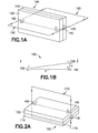
- Device 100 comprises a handset 110 having a slidable cover 120. As shown, a first microphone 130 is located on the handset 110, and a second microphone 140 and a third microphone 150 are located on the slidable cover 120.
- a horizontal plane 160 is generally perpendicular to the device 100.
- the microphones 130, 140, 150 are positioned relative to each other on the horizontal plane as shown in Figure 1B in which the first microphone 130 is separated from the second microphone 140 by a distance h and the second microphone 140 is separated from the third microphone by a distance d. In this mode, the microphones 130, 140, 150 are in optimal recording positions for video recording.
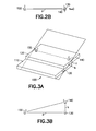
- a vertical plane 170 is generally perpendicular to the device 100.
- the same microphones 130, 140, 150 are positioned on the vertical plane 170 and thus generally cannot be used for detecting sound source directions since the distance h ⁇ 0, as shown in Figure 2B .
- the microphones 130, 140, 150 are moved to optimal positions.
- the distances d and h can be used for the capture of spatial audio directly from the microphones 130, 140, 150.
- the small elevation distance z ( Figure 3A ) denoting the distance between the second microphone 140 located on the slidable cover 120 and the first microphone 130 located on the handset 110 is negligible as long as h is approximately greater than z.
- the presence of a non-zero distance h enables the microphones 130, 140, 150 of the device 100 to discern whether a sound is arriving from in front of or behind the device 100.
- a method of directional analysis which is directly based on a correlation between audio channels defined by positions of the microphones 130, 140, 150 is selected.
- the direction of arriving sound is estimated independently for B frequency domain subbands in an effort to find the direction of a perceptually dominating sound source for every subband.
- DFT discrete Fourier transform
- ms milliseconds
- D max corresponds to the maximum delay in samples between the microphones.
- D HRTF is the maximum delay caused to the signal by head-related transfer function (HRTF) processing.
- N is the total length of the window considering the sinusoidal window (length N s ) and the additional D tot zeroes.
- the widths of the subbands can follow, for example, the equivalent rectangular bandwidth (ERB) scale.
- the directional analysis is performed. In doing so, the direction in which a sound source is located is estimated using two audio channels (for example, the channels defined by the positions of the second microphone 140 and the third microphone 150).
- the task is to find delay ⁇ b that maximizes the correlation between two channels for subband b.
- Re indicates the real part of the result
- * denotes the complex conjugate.
- X 2 , ⁇ b b and X 3 b are considered vectors with length of n b+ 1 - n b samples. Resolution of one sample is generally suitable for the search of the delay.
- ⁇ ⁇ b ⁇ cos - 1 ⁇ ⁇ 23 2 + 2 ⁇ b ⁇ ⁇ 23 - d 2 2 d b
- d is the distance between the second microphone 140 and the third microphone 150
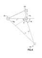
- b is the estimated distance between the source 180 and the nearest microphone (the second microphone 140, as shown in Figure 4 ).
- ⁇ b ⁇ ⁇ ⁇ b ⁇ b ⁇ 0 - ⁇ ⁇ b ⁇ b ⁇ 0 .
- a slidable camera lens cover can be used to optimize microphone positions in different applications.
- One microphone may be placed on a camera lens cover over a camera lens in a mobile device.
- the microphone positions in the device body and the lens cover may be such that when the lens cover is closed the microphone positions are optimal for recording speech for voice communications, and when the cover is open the microphone positions are optimal for recording stereo video.
- a device 200 for high quality noise cancellation for voice communications, a device 200 (such as a camera) has a first microphone 230 on a body portion 210 and a second microphone 240 on a slidable cover 220.
- the device 200 is configured such that the microphones 230, 240 are arranged to be close to each other.
- the microphones 230, 240 are also located so that they are close to the user's mouth when the device 200 is held in a normal talking position. If the microphones 230, 240 are close and aligned as shown in Figure 5A , beamforming may be used to obtain optimal voice quality in noisy environments. However, the same positioning may be less than desirable with regard to obtaining stereo recording in a video recording using the device 200 since the distance d in Figure 5B is essentially zero.
- a mobile device 300 may be configured to have four microphones, namely, a first microphone 310, a second microphone 320, a third microphone 330, and a fourth microphone 340, arranged as shown in Figure 7 .
- the first microphone 310 is located on a slidable member such as a slidable lens cover 350, which is located adjacent to a display 360 on a surface of the mobile device 300.
- a slidable member such as a slidable lens cover 350
- Such an arrangement of microphones on the mobile device 300 is optimal for noise cancellation with beamforming in normal voice communications and also for multichannel audio capture during videography using the mobile device in a landscape orientation.
- Figure 7 may not be optimal for video calls, where the mobile device 300 is held in a portrait orientation and where stereo audio is desired, as shown in Figure 8 .
- the slidable lens cover 350 is not moved to an open position to expose a lens 355, a distance D separating the first microphone 310 and the second microphone 320 (when both microphones are located on a plane 370) would be zero, as shown in Figure 7 .
- the third microphone 330 and the fourth microphone 340 would be blocked by the user's hand.
- the slidable member on a mobile device 400 is not limited to being a slidable lens cover, as it may be a slidable switch 450 or the like.
- Moving the slidable switch 450 may open an application where a new position of a microphone 410 (after sliding) improves quality of the captured audio. In doing so, the actual position of the microphone 410 may not change.
- Moving the slidable switch 450 may open and cover ports 420 through which sound can be transmitted, such ports 420 connecting the microphone 450 to the environment 460 outside the mobile device 400.
- a mobile device 500 it may be possible to move the apparent location of a video sensor 510 upon manipulation of a slidable cover 550 without moving the video sensor 510 itself.
- moving the apparent location of the video sensor 510 may be beneficial when depth maps are created with two cameras. If one of the cameras can be moved, then the apparent distance (which determines the optimum range for depth map calculation) between the two cameras is changed, and the depth maps can be made to work for a larger range of depths.
- this is not limited to an arrangement using two cameras, as it is possible to take two consecutive pictures with a single camera such that the apparent position of the camera is changed between the two pictures. If the two consecutive pictures are taken in quick succession from the same camera with a small but minimal movement of the camera, a depth map may then be calculated from the two pictures.
- a user may be notified to change microphone locations to achieve optimal performance. For example, if a device is oriented in a landscape mode and is in an open position or is on a table in a closed position, then the microphones of the device are likely in suboptimal positions. Device orientation can be detected using accelerometers inside the device. In such embodiments, the device notifies the user of a need to slide the device open or closed for optimal performance. This can be performed by a number of different methods.
- the device may show a video or moving graphic of a cover sliding to an open position or to a closed position; the device may play a sound that corresponds to a sound that comes from opening or closing the cover; the device may show a text such as "please open/close cover”; or the device may provide an audio instruction such as "please open/close cover.”
- Another method may be such that if audio is monitored during a video capture (e.g., from headphones or the like), the device could exaggerate a low quality audio signal caused by the moving parts of the device being in suboptimal positions for the current audio recording use case.
- the device could play back the audio signal to the monitoring headphones in mono and switch back to stereo once the microphone positions are changed to the optimal position.
- Still another method may be to show a red light next to a microphone that is in a suboptimal position. The light gradually turns green when the moving part with the microphone is moved to the optimal position. Combinations of the foregoing methods are also possible.
- the device operates under the existing parameters. For example, if the height h of the triangle in Figures 1-3 is too small, the device can either switch to recording stereo instead of multichannel 5.1 audio or binaural sound; the angle of the arriving sound (in Equation (7) above) can always be chosen to be positive, indicating that all directional sounds are rendered from the front of the device; or the device can record stereo but can use a blind surround upmixing algorithm (e.g., DOLBY PROLOGIC or the like) to create multichannel 5.1 audio from the stereo.
- a blind surround upmixing algorithm e.g., DOLBY PROLOGIC or the like
- the microphone locations with respect to each other may change continuously.
- the parameters d and h in the above equations are constantly updated.
- the bendable mobile phone may calculate new d and h values for the multichannel 5.1 audio or binaural capture algorithm once for every window. These values are used for that window only and the next window may have different values.
- Information regarding the directions of the sound sources may be used for applications other than multichannel 5.1 audio capture or binaural audio capture.
- sound directions may be used in the control of games.
- method 1100 one exemplary method of optimizing audio capture parameters in real time for a mobile device is designated generally by the reference number 1100 and is hereinafter referred to as "method 1100."
- input is designated regarding either a purely audio capture or a combination of audio and video capture. This input is embodied in an input step 1110.
- An analysis step 1120 is then executed in which directional analysis is performed to determine the optimal positions for microphones.
- the analysis step 1120 is carried out by a controller 1122 having a memory 1124 and a processor 1126.
- the feedback may comprise instructions to the user as to whether a slidable cover should be open or closed, whether the mobile device should be arranged in a landscape or portrait orientation, and/or the like. Audio capture is then carried out in an audio capture step 1140.
- An apparatus comprises at least one processor, and at least one memory including computer program code, the at least one memory and the computer program code configured to, with the at least one processor, cause the apparatus to: provide an audio capture event wherein one or more microphone configurations are configured to provide one or more audio signals based on at least one acoustic signal from at least one acoustic source, at least one of the one or more microphone configurations being defined by a first position of a first microphone configuration on a first portion and a second position of a second microphone configuration on a second portion, the second portion being movable relative to the first portion.
- the apparatus may be further caused to determine an optimal microphone configuration for the audio capture event using a directional analysis based on a correlation between audio channels defined by the first position of the first microphone configuration and the second position of the second microphone configuration.
- the apparatus may be further caused to provide a feedback regarding optimal positions for the first microphone configuration and the second microphone configuration for subsequent adjustment of the positions of the first microphone configuration and the second microphone configuration.
- the apparatus may be further caused to determine relative positions of the first microphone configuration and the second microphone configuration and configure the first microphone configuration and the second microphone configuration for optimal performance.
- the apparatus may be further caused to provide an indication to a user for the user to configure the first microphone configuration and the second microphone configuration for optimal performance.
- the second portion may be a cover, a slidable cover, a foldable portion, or a bendable portion of the apparatus.
- the first portion may include a camera and the second portion may be a slidable lens cover.
- the apparatus may further comprise a third microphone configuration. When the apparatus is positioned flat, a vertical plane through the first microphone configuration, the second microphone configuration, and the third microphone configuration may define a horizontal distance of zero between the first microphone configuration and the second microphone configuration when the apparatus is in the first position, and an optimal position for the audio capture event may comprise a horizontal non-zero distance between the first microphone configuration and the second microphone configuration when the apparatus is in the second position.
- the first microphone configuration and the second microphone configuration may comprise directional microphones.
- At least one of the first and second microphone configurations may comprise at least one of a microphone, one or more sound channels, and one or more sound inlets through which sound can be transmitted, the microphone being acoustically coupled to the one or more sound channels and the one or more sound inlets. At least one of the first and second microphone configurations may be modified by the movement of the second portion relative to the first portion.
- An electronic mobile device may comprise the apparatus.
- a method comprises providing an audio capture event wherein one or more microphone configurations are configured to provide one or more audio signals based on at least one acoustic signal from at least one acoustic source, at least one of the one or more microphone configurations being defined by a first position of a first microphone configuration on a first portion and a second position of a second microphone configuration on a second portion, the second portion being movable relative to the first portion.
- the method may further comprise determining an optimal microphone configuration for the audio capture event using a directional analysis based on a correlation between audio channels defined by the first position of the first microphone configuration and the second position of the second microphone configuration.
- Using a directional analysis may further comprise transforming a plurality of input channels to a frequency domain using discrete Fourier transform.
- the method may further comprise dividing the frequency domain into subbands.
- the method may further comprise providing a feedback regarding optimal positions for the first microphone configuration and the second microphone configuration for subsequent adjustment of the first position of the first microphone configuration and the second position of the second microphone configuration.
- the method may further comprise determining relative positions of the first microphone configuration and the second microphone configuration and configuring the first and second microphone configurations for optimal performance.
- An indication may be provided to a user for the user to configure the microphone configurations for optimal performance.
- the microphone configuration may be further defined by a third microphone configuration on the first portion or the second portion.
- Providing a feedback regarding optimal positions for the plurality of microphones may comprise one or more of exaggerating a low quality audio output to the user, illuminating a light, providing a text graphic, and providing an audio instruction.
- a process comprises providing an audio capture event wherein one or more microphone configurations are configured to provide one or more audio signals based on at least one acoustic signal from at least one acoustic source, at least one of the one or more microphone configurations being defined by a first position of a first microphone configuration on a first portion and a second microphone configuration on a second portion, the second portion being movable relative to the first portion between the first position and a second position.
Landscapes
- Physics & Mathematics (AREA)
- Engineering & Computer Science (AREA)
- Acoustics & Sound (AREA)
- Signal Processing (AREA)
- Health & Medical Sciences (AREA)
- Otolaryngology (AREA)
- General Health & Medical Sciences (AREA)
- Circuit For Audible Band Transducer (AREA)
- Obtaining Desirable Characteristics In Audible-Bandwidth Transducers (AREA)
Abstract
Description
- The exemplary and non-limiting embodiments described herein relate generally to the detection and capture of audio signals and, more particularly, to the analysis of directional information of audio signals detected and captured by a mobile device.
- Spatial audio capture involves the capture of sound for the subsequent reproduction and artificial re-creation of the sound. One type of spatial audio capture is binaural audio capture, in which microphones capture directional information as sound in a horizontal plane for the re-creation of the sound via speakers arranged to produce a three-dimensional (3-D) audio sensation through headphones. Another type of spatial audio capture is multichannel 5.1 audio capture, in which microphones capture directional information as sound in the horizontal plane and re-create that sound through five full-bandwidth channels and one low frequency effect channel to produce a 3-D audio sensation.
- The following summary is merely intended to be exemplary. The summary is not intended to limit the scope of the claims. In accordance with one aspect, an apparatus comprises: at least one processor, and at least one memory including computer program code, the at least one memory and the computer program code configured to, with the at least one processor, cause the apparatus to: provide an audio capture event wherein one or more microphone configurations are configured to provide one or more audio signals based on at least one acoustic signal from at least one acoustic source, at least one of the one or more microphone configurations being defined by a first position of a first microphone configuration on a first portion and a second position of a second microphone configuration on a second portion, the second portion being movable relative to the first portion.
- In accordance with another aspect, a method comprises providing an audio capture event wherein one or more microphone configurations are configured to provide one or more audio signals based on at least one acoustic signal from at least one acoustic source, at least one of the one or more microphone configurations being defined by a first position of a first microphone configuration on a first portion and a second position of a second microphone configuration on a second portion, the second portion being movable relative to the first portion.
- The foregoing aspects and other features are explained in the following description, taken in connection with the accompanying drawings, wherein:
-
Figure 1A is a perspective view of a mobile device in a video capture orientation; -
Figure 1B is a schematic representation of positions of microphones in the mobile device in the orientation ofFigure 1A ; -
Figure 2A is a perspective view of the mobile device with a cover thereof closed; -
Figure 2B is a schematic representation of positions of microphones in the mobile device in the orientation ofFigure 2A ; -
Figure 3A is a perspective view of the mobile device in an audio capture orientation; -
Figure 3B is a schematic representation of positions of microphones in the mobile device in the orientation ofFigure 3A ; -
Figure 4 is a graphical representation of the calculation of an angle of sound arriving at a device having a plurality of microphones; -
Figure 5A is a perspective view of a camera with a lens cover in a closed position; -
Figure 5B is a top view of the camera ofFigure 5A showing positions of microphones in the camera; -
Figure 6A is a perspective view of a camera with a lens cover in an open position; -
Figure 6B is a top view of the camera ofFigure 6A showing positions of microphones in the camera; -
Figure 7 is a perspective view of a camera in a landscape orientation showing locations of four microphones; -
Figure 8 is a perspective view of a camera in a video call orientation showing locations of four microphones; -
Figure 9 is a schematic view of a device showing a part that is moved to open and close a port in which a microphone is located; -
Figure 10 is a schematic view of a device showing a part that is moved to open and close a port to move an apparent location of a sensor in the device; and -
Figure 11 is a flow of one exemplary method of optimizing audio capture parameters in real time for a mobile device. - Directional detection of sounds from one or more sound sources is optimal when the sound sources are arranged on the same plane with three or more directional microphones. In detecting the direction of sounds through such microphones, whether the sound source is located above or below a horizontal plane cannot be discerned. Nevertheless, when the microphone plane is horizontal, knowing whether the sound source was above or below the plane is of little value, since playback of the sound in a multichannel 5.1 audio format cannot reproduce sounds from above or below the horizontal plane. Furthermore, knowing whether the sound is above or below the horizontal plane is not very useful for playback in a binaural format. On the other hand, if the microphone plane is vertical, then "above the plane" can refer to "in front of the device" and "below the plane" can refer to "behind the device" (or vice versa). In vertical orientations of the microphone plane, whether the sound emanates from in front of or behind the device is useful information.
- Stereo audio can be recorded with two omni-directional microphones that are separated from each other in a horizontal direction. Directional microphones generally cannot be used for recording stereo audio in such a configuration because of their directionality, which facilitates their operability only in certain orientations.
- However, there are many uses for directional microphones in mobile devices. Such uses include, for example, surround sound capture for video recordings and surround sound teleconferencing. In any use, however, the microphones provide for an audio capture event such as a pure audio capture (receipt of audio without further processing), audio recording, audio/visual recording, or any other use case associated with receiving an audio signal.
- A mobile device may be used in different physical orientations depending on the use scenario. Video is usually recorded on a mobile device when the mobile device is in a landscape orientation. In teleconferencing in which multiple people are providing audio input without video, however, the mobile device, which is generally a mobile phone, is usually laid flat on a table or other surface. During teleconferencing that includes video, the mobile device is usually held in a user's hand or placed on a surface so as to remain in a portrait orientation. In order to make the device work in different orientations (both landscape and portrait), more microphones are needed than is required to make the device work in only one orientation. In the past, additional microphones have been incorporated into mobile devices to render the mobile devices operable in multiple orientations. Referring now to the Figures, in some embodiments described herein, audio capture parameters in real time can be optimized by adjusting the locations of microphones relative to other microphones. To do so, the microphones are located on a moving part of a mobile device (e.g., a slidable, foldable, or otherwise operable part), or the mobile device itself may be bendable or otherwise configurable by the user.
- In other embodiments, microphones may be intentionally located on moving parts of the mobile device such that when the parts are moved, various effects may be realized. For example, upon moving parts of the mobile device, an application may be triggered to start, a microphone may move to a location that provides for the optimal capture of audio for the application, and/or another sensor may be revealed (e.g., a camera or additional microphone may be revealed from behind the moving part).
- In still other embodiments, a microphone may be located on a moving part of the mobile device such that in one position of the moving part the microphone is optimal for recording in one orientation of the mobile device and in another position of the moving part the microphone is optimal for another orientation of the mobile device.
- In still other embodiments, a moving part of the mobile device may be used to open and close microphone ports so that the effective microphone position varies. In such embodiments, the moving part may simultaneously start an application for which the new effective microphone position is preferred over the previous microphone position. Additionally, or in the alternative, the moving part may reveal another sensor or a camera.
- In still other embodiments, a user interface (UI) may prompt a user to move the moving part so that microphones are moved to an optimal position for a current application. This can be done, for example, by providing audio output to the user through a headphone audio system where quality problems caused by suboptimal microphone locations are exaggerated or, for example, cause the illumination of a light near the microphone that should be moved.
- Referring more specifically now to
Figure 1A , a mobile device is designated generally by thereference number 100 and is hereinafter referred to as "device 100."Device 100 comprises ahandset 110 having aslidable cover 120. As shown, afirst microphone 130 is located on thehandset 110, and asecond microphone 140 and athird microphone 150 are located on theslidable cover 120. When thedevice 100 is positioned in a landscape mode for video recording, ahorizontal plane 160 is generally perpendicular to thedevice 100. When thehorizontal plane 160 is generally perpendicular to thedevice 100, themicrophones Figure 1B in which thefirst microphone 130 is separated from thesecond microphone 140 by a distance h and thesecond microphone 140 is separated from the third microphone by a distance d. In this mode, themicrophones - However, when the
device 100 is closed and positioned flat on a table or other surface as shown inFigure 2A in preparation for an audio teleconferencing application, avertical plane 170 is generally perpendicular to thedevice 100. In this configuration of the microphones, thesame microphones vertical plane 170 and thus generally cannot be used for detecting sound source directions since the distance h ≈ 0, as shown inFigure 2B . - Referring now to
Figure 3A , when theslidable cover 120 is opened for the audio teleconferencing application, themicrophones Figure 3B , the distances d and h can be used for the capture of spatial audio directly from themicrophones Figure 3A ) denoting the distance between thesecond microphone 140 located on theslidable cover 120 and thefirst microphone 130 located on thehandset 110 is negligible as long as h is approximately greater than z. - Referring to
Figures 1A-3B , the presence of a non-zero distance h enables themicrophones device 100 to discern whether a sound is arriving from in front of or behind thedevice 100. - To determine the optimal positions for the
microphones microphones - In such a method of directional analysis, every input channel k = 1, ..., 3 is transformed to a frequency domain using discrete Fourier transform (DFT). Sinusoidal windows with 50% overlap and an effective length of 20 milliseconds (ms) are used. Before the DFT transform Dtot=Dmax+DHRTF, zeroes are added to the end of the window. Dmax corresponds to the maximum delay in samples between the microphones. In the microphone setup presented in
Figures 1A and 1B , the maximum delay is obtained as:
where Fs is the sampling rate of signal and v is the speed of the sound in the air. DHRTF is the maximum delay caused to the signal by head-related transfer function (HRTF) processing. - After the DFT transform, the frequency domain representation Xk(n) of all three channels, k = 1, ..., 3, n = 0, ..., N-1, is presented. N is the total length of the window considering the sinusoidal window (length Ns ) and the additional Dtot zeroes. Frequency domain representation is divided into B subbands:

where nb is the first index of the bth subband. The widths of the subbands can follow, for example, the equivalent rectangular bandwidth (ERB) scale. - For every subband, the directional analysis is performed. In doing so, the direction in which a sound source is located is estimated using two audio channels (for example, the channels defined by the positions of the
second microphone 140 and the third microphone 150). The task is to find delay τb that maximizes the correlation between two channels for subband b. Frequency domain representation of, e.g.,

- Now the optimal delay is obtained from:

where Re indicates the real part of the result and * denotes the complex conjugate.

- In the sum signal, the content of the channel in which an event occurs first is added as such, whereas the channel in which the event occurs later is shifted to obtain the best match. Shift τb indicates how much closer the sound source is to the
second microphone 140 than thethird microphone 150. The actual distance can be calculated as:
- Utilizing basic geometry on the setup in
Figures 1A and 1B , and referring now toFigure 4 , it can be calculated that the angle of the arriving sound from asource 180 is equal to:
where d is the distance between thesecond microphone 140 and thethird microphone 150 and where b is the estimated distance between thesource 180 and the nearest microphone (thesecond microphone 140, as shown inFigure 4 ). Typically b can be set to a fixed value. For example, b = 2 meters has been found to provide stable results. - There are two alternatives for the direction of the arriving sound as the exact direction cannot be determined with only two microphones. One is from the front and the other is from behind the microphones. The third microphone is utilized to define which of the signs in equation (7) is correct:

where δb is the delay between first and second channels (X1 and X2), the first channel being shifted relative to the second channel to achieve maximum correlation, and the delay being calculated for each frequency band b. If δb is positive, then thesource 180 is closer to thesecond microphone 140 than thefirst microphone 130 and thus αb is positive:
- Thus, it can be determined for each frequency band which direction the sound is coming from. In particular, h is the height of the triangle and depends on whether the cover is open or closed and in which orientation the phone is placed. This h can be calculated when the microphone placement and the cover position are known. For example:
H (meters) 0.01 Landscape orientation, cover closed, device thickness = 10 millimeters (mm) 0.0001 Teleconference orientation, cover closed 0.0199 Teleconference orientation, cover open, slide distance = 20 mm - In other exemplary embodiments, a slidable camera lens cover can be used to optimize microphone positions in different applications. One microphone may be placed on a camera lens cover over a camera lens in a mobile device. The microphone positions in the device body and the lens cover may be such that when the lens cover is closed the microphone positions are optimal for recording speech for voice communications, and when the cover is open the microphone positions are optimal for recording stereo video.
- Referring now to
Figures 5 and 6 , an example of such an arrangement is shown. As shown inFigures 5A and 5B , for high quality noise cancellation for voice communications, a device 200 (such as a camera) has afirst microphone 230 on abody portion 210 and asecond microphone 240 on a slidable cover 220. Thedevice 200 is configured such that themicrophones microphones device 200 is held in a normal talking position. If themicrophones Figure 5A , beamforming may be used to obtain optimal voice quality in noisy environments. However, the same positioning may be less than desirable with regard to obtaining stereo recording in a video recording using thedevice 200 since the distance d inFigure 5B is essentially zero. - As shown in
Figure 6A , when thesecond microphone 240 is on the slidable cover 220 of the device 200 (when thedevice 200 is a camera and the slidable cover 220 is a lens cover over a lens 265), then the slidable cover 220 is moved when the camera is used for video recording. The position to which thesecond microphone 240 moves when the slidable cover 220 is opened is more suitable for stereo recording since, as shown inFigure 6B , the distance d is greatly increased relative to the distance d as shown inFigure 5B . - Referring now to
Figures 7 and 8 , another example of such an arrangement is shown. Amobile device 300 may be configured to have four microphones, namely, afirst microphone 310, asecond microphone 320, athird microphone 330, and afourth microphone 340, arranged as shown inFigure 7 . Thefirst microphone 310 is located on a slidable member such as aslidable lens cover 350, which is located adjacent to adisplay 360 on a surface of themobile device 300. Such an arrangement of microphones on themobile device 300 is optimal for noise cancellation with beamforming in normal voice communications and also for multichannel audio capture during videography using the mobile device in a landscape orientation. - However, the arrangement of
Figure 7 may not be optimal for video calls, where themobile device 300 is held in a portrait orientation and where stereo audio is desired, as shown inFigure 8 . In particular, if theslidable lens cover 350 is not moved to an open position to expose alens 355, a distance D separating thefirst microphone 310 and the second microphone 320 (when both microphones are located on a plane 370) would be zero, as shown inFigure 7 . In such a configuration of the microphones, stereo recording would be impossible. Also, in holding themobile device 300 in the portrait orientation, as shown inFigure 8 , thethird microphone 330 and thefourth microphone 340 would be blocked by the user's hand. - As shown in
Figure 9 , the slidable member on amobile device 400 is not limited to being a slidable lens cover, as it may be aslidable switch 450 or the like. Moving theslidable switch 450 may open an application where a new position of a microphone 410 (after sliding) improves quality of the captured audio. In doing so, the actual position of the microphone 410 may not change. Moving theslidable switch 450 may open and coverports 420 through which sound can be transmitted,such ports 420 connecting themicrophone 450 to theenvironment 460 outside themobile device 400. - Referring now to
Figure 10 , in some exemplary embodiments of amobile device 500, it may be possible to move the apparent location of avideo sensor 510 upon manipulation of aslidable cover 550 without moving thevideo sensor 510 itself. For example, moving the apparent location of the video sensor 510 (when thevideo sensor 510 is a camera lens) may be beneficial when depth maps are created with two cameras. If one of the cameras can be moved, then the apparent distance (which determines the optimum range for depth map calculation) between the two cameras is changed, and the depth maps can be made to work for a larger range of depths. However, this is not limited to an arrangement using two cameras, as it is possible to take two consecutive pictures with a single camera such that the apparent position of the camera is changed between the two pictures. If the two consecutive pictures are taken in quick succession from the same camera with a small but minimal movement of the camera, a depth map may then be calculated from the two pictures. - In any of the exemplary embodiments disclosed herein, a user may be notified to change microphone locations to achieve optimal performance. For example, if a device is oriented in a landscape mode and is in an open position or is on a table in a closed position, then the microphones of the device are likely in suboptimal positions. Device orientation can be detected using accelerometers inside the device. In such embodiments, the device notifies the user of a need to slide the device open or closed for optimal performance. This can be performed by a number of different methods. For example, the device may show a video or moving graphic of a cover sliding to an open position or to a closed position; the device may play a sound that corresponds to a sound that comes from opening or closing the cover; the device may show a text such as "please open/close cover"; or the device may provide an audio instruction such as "please open/close cover." Another method may be such that if audio is monitored during a video capture (e.g., from headphones or the like), the device could exaggerate a low quality audio signal caused by the moving parts of the device being in suboptimal positions for the current audio recording use case. For example, if the current position of the microphones causes the stereo image to be very narrow, the device could play back the audio signal to the monitoring headphones in mono and switch back to stereo once the microphone positions are changed to the optimal position. Still another method may be to show a red light next to a microphone that is in a suboptimal position. The light gradually turns green when the moving part with the microphone is moved to the optimal position. Combinations of the foregoing methods are also possible.
- To improve suboptimal microphone locations, in some cases the user may choose to ignore the prompting to slide the cover open or closed. In this case, the device operates under the existing parameters. For example, if the height h of the triangle in
Figures 1-3 is too small, the device can either switch to recording stereo instead of multichannel 5.1 audio or binaural sound; the angle of the arriving sound (in Equation (7) above) can always be chosen to be positive, indicating that all directional sounds are rendered from the front of the device; or the device can record stereo but can use a blind surround upmixing algorithm (e.g., DOLBY PROLOGIC or the like) to create multichannel 5.1 audio from the stereo. In other efforts to improve suboptimal microphone locations, adaptations may be made when the microphone locations are constantly changing. In bendable products such as a bendable mobile phone, the microphone locations with respect to each other may change continuously. With such devices the parameters d and h in the above equations are constantly updated. For example, the bendable mobile phone may calculate new d and h values for the multichannel 5.1 audio or binaural capture algorithm once for every window. These values are used for that window only and the next window may have different values. - Information regarding the directions of the sound sources may be used for applications other than multichannel 5.1 audio capture or binaural audio capture. For example, sound directions may be used in the control of games.
- In any of the exemplary embodiments described above, it is possible to use a mobile device for audio recording in more orientations without incorporating additional microphones. Referring now to
Figure 11 , one exemplary method of optimizing audio capture parameters in real time for a mobile device is designated generally by thereference number 1100 and is hereinafter referred to as "method 1100." In themethod 1100, input is designated regarding either a purely audio capture or a combination of audio and video capture. This input is embodied in aninput step 1110. Ananalysis step 1120 is then executed in which directional analysis is performed to determine the optimal positions for microphones. Theanalysis step 1120 is carried out by acontroller 1122 having amemory 1124 and aprocessor 1126. Feedback regarding optimal positions for the microphone(s) is then provided in afeedback step 1130. The feedback may comprise instructions to the user as to whether a slidable cover should be open or closed, whether the mobile device should be arranged in a landscape or portrait orientation, and/or the like. Audio capture is then carried out in anaudio capture step 1140. - An apparatus comprises at least one processor, and at least one memory including computer program code, the at least one memory and the computer program code configured to, with the at least one processor, cause the apparatus to: provide an audio capture event wherein one or more microphone configurations are configured to provide one or more audio signals based on at least one acoustic signal from at least one acoustic source, at least one of the one or more microphone configurations being defined by a first position of a first microphone configuration on a first portion and a second position of a second microphone configuration on a second portion, the second portion being movable relative to the first portion. The apparatus may be further caused to determine an optimal microphone configuration for the audio capture event using a directional analysis based on a correlation between audio channels defined by the first position of the first microphone configuration and the second position of the second microphone configuration. The apparatus may be further caused to provide a feedback regarding optimal positions for the first microphone configuration and the second microphone configuration for subsequent adjustment of the positions of the first microphone configuration and the second microphone configuration. The apparatus may be further caused to determine relative positions of the first microphone configuration and the second microphone configuration and configure the first microphone configuration and the second microphone configuration for optimal performance. The apparatus may be further caused to provide an indication to a user for the user to configure the first microphone configuration and the second microphone configuration for optimal performance. The second portion may be a cover, a slidable cover, a foldable portion, or a bendable portion of the apparatus. The first portion may include a camera and the second portion may be a slidable lens cover. The apparatus may further comprise a third microphone configuration. When the apparatus is positioned flat, a vertical plane through the first microphone configuration, the second microphone configuration, and the third microphone configuration may define a horizontal distance of zero between the first microphone configuration and the second microphone configuration when the apparatus is in the first position, and an optimal position for the audio capture event may comprise a horizontal non-zero distance between the first microphone configuration and the second microphone configuration when the apparatus is in the second position. The first microphone configuration and the second microphone configuration may comprise directional microphones. At least one of the first and second microphone configurations may comprise at least one of a microphone, one or more sound channels, and one or more sound inlets through which sound can be transmitted, the microphone being acoustically coupled to the one or more sound channels and the one or more sound inlets. At least one of the first and second microphone configurations may be modified by the movement of the second portion relative to the first portion. An electronic mobile device may comprise the apparatus.
- A method comprises providing an audio capture event wherein one or more microphone configurations are configured to provide one or more audio signals based on at least one acoustic signal from at least one acoustic source, at least one of the one or more microphone configurations being defined by a first position of a first microphone configuration on a first portion and a second position of a second microphone configuration on a second portion, the second portion being movable relative to the first portion. The method may further comprise determining an optimal microphone configuration for the audio capture event using a directional analysis based on a correlation between audio channels defined by the first position of the first microphone configuration and the second position of the second microphone configuration. Using a directional analysis may further comprise transforming a plurality of input channels to a frequency domain using discrete Fourier transform. The method may further comprise dividing the frequency domain into subbands. The method may further comprise providing a feedback regarding optimal positions for the first microphone configuration and the second microphone configuration for subsequent adjustment of the first position of the first microphone configuration and the second position of the second microphone configuration. The method may further comprise determining relative positions of the first microphone configuration and the second microphone configuration and configuring the first and second microphone configurations for optimal performance. An indication may be provided to a user for the user to configure the microphone configurations for optimal performance. The microphone configuration may be further defined by a third microphone configuration on the first portion or the second portion. Providing a feedback regarding optimal positions for the plurality of microphones may comprise one or more of exaggerating a low quality audio output to the user, illuminating a light, providing a text graphic, and providing an audio instruction.
- In a non-transitory computer readable storage medium encoded with instructions that, if executed by a computer, perform a process, the process comprises providing an audio capture event wherein one or more microphone configurations are configured to provide one or more audio signals based on at least one acoustic signal from at least one acoustic source, at least one of the one or more microphone configurations being defined by a first position of a first microphone configuration on a first portion and a second microphone configuration on a second portion, the second portion being movable relative to the first portion between the first position and a second position.
- It should be understood that the foregoing description is only illustrative. Various alternatives and modifications can be devised by those skilled in the art. For example, features recited in the various dependent claims could be combined with each other in any suitable combination(s). In addition, features from different embodiments described above could be selectively combined into a new embodiment. Accordingly, the description is intended to embrace all such alternatives, modifications and variances which fall within the scope of the appended claims.
Claims (15)
- A method, comprising:providing an audio capture event wherein one or more microphone configurations are configured to provide one or more audio signals based on at least one acoustic signal from at least one acoustic source, at least one of the one or more microphone configurations being defined by a first position of a first microphone configuration on a first portion and a second position of a second microphone configuration on a second portion, the second portion being movable relative to the first portion.
- The method as claimed in claim 1, further comprising determining an optimal microphone configuration for the audio capture event using a directional analysis based on a correlation between audio channels defined by the first position of the first microphone configuration and the second position of the second microphone configuration.
- The method as claimed in any of claim 1 or 2, wherein using a directional analysis further comprises transforming a plurality of input channels to a frequency domain using discrete Fourier transform.
- The method as claimed in any preceding claim, further comprising providing a feedback regarding optimal positions for the first microphone configuration and the second microphone configuration for subsequent adjustment of the first position of the first microphone configuration and the second position of the second microphone configuration.
- The method as claimed in claim 4, further comprising determining relative positions of the first microphone configuration and the second microphone configuration and configuring the first microphone configuration and the second microphone configuration for optimal performance.
- The method as claimed in any of claim 4 or 5, further comprising providing an indication to a user for the user to configure the first microphone configuration and the second microphone configuration for optimal performance.
- The method as claimed in any preceding claim, wherein the microphone configuration is further defined by a third microphone configuration on the first portion or the second portion.
- The method of any of claims 4 to 7, wherein providing a feedback regarding optimal positions for a plurality of microphones comprises one or more of exaggerating a low quality audio output to the user, illuminating a light, providing a text graphic, and providing an audio instruction.
- The method as claimed in any preceding claim, wherein the second portion is one of a cover, a slidable cover, a foldable portion, an operable section, or a bendable portion of an apparatus.
- The method as claimed in claim 9, wherein when the apparatus is positioned flat, a vertical plane through the first microphone configuration, the second microphone configuration, and the third microphone configuration define a horizontal distance of zero between the first microphone configuration and the second microphone configuration when the apparatus is in the first position.
- The method as claimed in claim 10, wherein an optimal position for the audio capture event comprises a horizontal non-zero distance between a first microphone and a second microphone when the apparatus is in the second position.
- The method as claimed in any preceding claim, wherein the at least one of the first and second microphone configurations is modified by the movement of the second portion relative to the first portion.
- The method as claimed in any preceding claim, wherein at least one of the first and second microphone configurations comprise at least one of,
a microphone,
one or more sound channels, and
one or more sound inlets through which sound can be transmitted,
wherein the microphone is acoustically coupled to the one or more sound channels and the one or more sound inlets. - The method as claimed in claim 13, wherein the microphone is located on one of the first and second portions such that one of the first and second portions is moved in one position wherein the microphone is optimal for recording and the microphone is optimal in another position based on the position of one of the first and second portions.
- An apparatus configured to perform the actions of the method of any of claims 1 to 14.
Applications Claiming Priority (1)
| Application Number | Priority Date | Filing Date | Title |
|---|---|---|---|
| US14/061,041 US9894454B2 (en) | 2013-10-23 | 2013-10-23 | Multi-channel audio capture in an apparatus with changeable microphone configurations |
Publications (2)
| Publication Number | Publication Date |
|---|---|
| EP2866463A1 true EP2866463A1 (en) | 2015-04-29 |
| EP2866463B1 EP2866463B1 (en) | 2021-04-07 |
Family
ID=51786840
Family Applications (1)
| Application Number | Title | Priority Date | Filing Date |
|---|---|---|---|
| EP14189823.9A Active EP2866463B1 (en) | 2013-10-23 | 2014-10-22 | Multi-channel audio capture in an apparatus with changeable microphone configurations |
Country Status (2)
| Country | Link |
|---|---|
| US (1) | US9894454B2 (en) |
| EP (1) | EP2866463B1 (en) |
Families Citing this family (14)
| Publication number | Priority date | Publication date | Assignee | Title |
|---|---|---|---|---|
| JP6204618B2 (en) * | 2014-02-10 | 2017-09-27 | ボーズ・コーポレーションBose Corporation | Conversation support system |
| US9788109B2 (en) | 2015-09-09 | 2017-10-10 | Microsoft Technology Licensing, Llc | Microphone placement for sound source direction estimation |
| WO2017143067A1 (en) | 2016-02-19 | 2017-08-24 | Dolby Laboratories Licensing Corporation | Sound capture for mobile devices |
| GB201607455D0 (en) * | 2016-04-29 | 2016-06-15 | Nokia Technologies Oy | An apparatus, electronic device, system, method and computer program for capturing audio signals |
| GB2556093A (en) * | 2016-11-18 | 2018-05-23 | Nokia Technologies Oy | Analysis of spatial metadata from multi-microphones having asymmetric geometry in devices |
| US10127920B2 (en) | 2017-01-09 | 2018-11-13 | Google Llc | Acoustic parameter adjustment |
| US9820073B1 (en) | 2017-05-10 | 2017-11-14 | Tls Corp. | Extracting a common signal from multiple audio signals |
| US10129648B1 (en) * | 2017-05-11 | 2018-11-13 | Microsoft Technology Licensing, Llc | Hinged computing device for binaural recording |
| US10419853B2 (en) | 2018-02-21 | 2019-09-17 | Apple Inc. | Binaural audio capture using untethered wireless headset |
| CN109462800A (en) * | 2018-12-28 | 2019-03-12 | 北京小米移动软件有限公司 | A kind of electronic equipment with two-channel |
| KR102588489B1 (en) | 2019-05-23 | 2023-10-12 | 삼성전자주식회사 | A foldable electronic device including a plurality of acoustical input units |
| EP3827875B1 (en) | 2019-11-27 | 2023-07-05 | ONWARD Medical N.V. | Neuromodulation system |
| US20250080904A1 (en) * | 2023-09-01 | 2025-03-06 | Google Llc | Capturing Spatial Sound on Unmodified Mobile Devices with the Aid of an Inertial Measurement Unit |
| CN120748448B (en) * | 2025-09-03 | 2025-12-12 | 上海浩宜信息科技有限公司 | AI-based intelligent badge collection and analysis method and system |
Citations (3)
| Publication number | Priority date | Publication date | Assignee | Title |
|---|---|---|---|---|
| JP2005286718A (en) * | 2004-03-30 | 2005-10-13 | Casio Comput Co Ltd | IMAGING DEVICE, VOICE INPUT CONTROL METHOD AND PROGRAM USED FOR THIS IMAGING DEVICE |
| US20120224716A1 (en) * | 2011-03-02 | 2012-09-06 | Panasonic Corporation | Sound pickup device |
| US20130202114A1 (en) * | 2010-11-19 | 2013-08-08 | Nokia Corporation | Controllable Playback System Offering Hierarchical Playback Options |
Family Cites Families (15)
| Publication number | Priority date | Publication date | Assignee | Title |
|---|---|---|---|---|
| US8947347B2 (en) | 2003-08-27 | 2015-02-03 | Sony Computer Entertainment Inc. | Controlling actions in a video game unit |
| JP3918730B2 (en) | 2002-12-20 | 2007-05-23 | 富士ゼロックス株式会社 | Microphone array and sound pressure distribution analysis system |
| ATE339757T1 (en) | 2003-06-17 | 2006-10-15 | Sony Ericsson Mobile Comm Ab | METHOD AND DEVICE FOR VOICE ACTIVITY DETECTION |
| US7099821B2 (en) * | 2003-09-12 | 2006-08-29 | Softmax, Inc. | Separation of target acoustic signals in a multi-transducer arrangement |
| JP2005341384A (en) * | 2004-05-28 | 2005-12-08 | Sony Corp | Sound field correction apparatus and sound field correction method |
| US7920698B1 (en) | 2006-10-17 | 2011-04-05 | At&T Mobility Ii Llc | Microphone systems for telephones |
| US9445193B2 (en) | 2008-07-31 | 2016-09-13 | Nokia Technologies Oy | Electronic device directional audio capture |
| CA2765116C (en) * | 2009-06-23 | 2020-06-16 | Nokia Corporation | Method and apparatus for processing audio signals |
| RU2529591C2 (en) | 2009-06-30 | 2014-09-27 | Нокиа Корпорейшн | Elimination of position uncertainty when generating surround sound |
| JP5407848B2 (en) | 2009-12-25 | 2014-02-05 | 富士通株式会社 | Microphone directivity control device |
| US20120013750A1 (en) * | 2010-07-16 | 2012-01-19 | Gn Netcom A/S | Sound Optimization Via Camera |
| US9313599B2 (en) | 2010-11-19 | 2016-04-12 | Nokia Technologies Oy | Apparatus and method for multi-channel signal playback |
| US9456289B2 (en) | 2010-11-19 | 2016-09-27 | Nokia Technologies Oy | Converting multi-microphone captured signals to shifted signals useful for binaural signal processing and use thereof |
| US9654609B2 (en) * | 2011-12-16 | 2017-05-16 | Qualcomm Incorporated | Optimizing audio processing functions by dynamically compensating for variable distances between speaker(s) and microphone(s) in an accessory device |
| US9236050B2 (en) * | 2013-03-14 | 2016-01-12 | Vocollect Inc. | System and method for improving speech recognition accuracy in a work environment |
-
2013
- 2013-10-23 US US14/061,041 patent/US9894454B2/en not_active Expired - Fee Related
-
2014
- 2014-10-22 EP EP14189823.9A patent/EP2866463B1/en active Active
Patent Citations (3)
| Publication number | Priority date | Publication date | Assignee | Title |
|---|---|---|---|---|
| JP2005286718A (en) * | 2004-03-30 | 2005-10-13 | Casio Comput Co Ltd | IMAGING DEVICE, VOICE INPUT CONTROL METHOD AND PROGRAM USED FOR THIS IMAGING DEVICE |
| US20130202114A1 (en) * | 2010-11-19 | 2013-08-08 | Nokia Corporation | Controllable Playback System Offering Hierarchical Playback Options |
| US20120224716A1 (en) * | 2011-03-02 | 2012-09-06 | Panasonic Corporation | Sound pickup device |
Also Published As
| Publication number | Publication date |
|---|---|
| EP2866463B1 (en) | 2021-04-07 |
| US20150110275A1 (en) | 2015-04-23 |
| US9894454B2 (en) | 2018-02-13 |
Similar Documents
| Publication | Publication Date | Title |
|---|---|---|
| EP2866463B1 (en) | Multi-channel audio capture in an apparatus with changeable microphone configurations | |
| US12061835B2 (en) | Binaural rendering for headphones using metadata processing | |
| US9854378B2 (en) | Audio spatial rendering apparatus and method | |
| US10818300B2 (en) | Spatial audio apparatus | |
| EP3520216B1 (en) | Gain control in spatial audio systems | |
| JP6121481B2 (en) | 3D sound acquisition and playback using multi-microphone | |
| EP2824663B1 (en) | Audio processing apparatus | |
| CN102859584B (en) | Device and method for converting a first parametric spatial audio signal into a second parametric spatial audio signal | |
| US10397722B2 (en) | Distributed audio capture and mixing | |
| EP3320692B1 (en) | Spatial audio processing apparatus | |
| EP2589231B1 (en) | Facilitating communications using a portable communication device and directed sound output | |
| CN105264911B (en) | Audio frequency apparatus | |
| EP3238461B1 (en) | Audio processing based upon camera selection | |
| Kowalczyk et al. | Parametric spatial sound processing: A flexible and efficient solution to sound scene acquisition, modification, and reproduction | |
| JP2010206451A (en) | Speaker with camera, signal processing apparatus, and av system | |
| JP2015019371A5 (en) | ||
| GB2587335A (en) | Direction estimation enhancement for parametric spatial audio capture using broadband estimates | |
| JP2024502732A (en) | Post-processing of binaural signals | |
| JP2025148391A (en) | Spatial Audio Filtering within Spatial Audio Capture | |
| US20250008263A1 (en) | Audio Transducer Implementation Enhancements |
Legal Events
| Date | Code | Title | Description |
|---|---|---|---|
| PUAI | Public reference made under article 153(3) epc to a published international application that has entered the european phase |
Free format text: ORIGINAL CODE: 0009012 |
|
| 17P | Request for examination filed |
Effective date: 20141022 |
|
| AK | Designated contracting states |
Kind code of ref document: A1 Designated state(s): AL AT BE BG CH CY CZ DE DK EE ES FI FR GB GR HR HU IE IS IT LI LT LU LV MC MK MT NL NO PL PT RO RS SE SI SK SM TR |
|
| AX | Request for extension of the european patent |
Extension state: BA ME |
|
| RAP1 | Party data changed (applicant data changed or rights of an application transferred) |
Owner name: NOKIA TECHNOLOGIES OY |
|
| R17P | Request for examination filed (corrected) |
Effective date: 20151029 |
|
| RBV | Designated contracting states (corrected) |
Designated state(s): AL AT BE BG CH CY CZ DE DK EE ES FI FR GB GR HR HU IE IS IT LI LT LU LV MC MK MT NL NO PL PT RO RS SE SI SK SM TR |
|
| STAA | Information on the status of an ep patent application or granted ep patent |
Free format text: STATUS: EXAMINATION IS IN PROGRESS |
|
| 17Q | First examination report despatched |
Effective date: 20171020 |
|
| REG | Reference to a national code |
Ref country code: DE Ref legal event code: R079 Ref document number: 602014076320 Country of ref document: DE Free format text: PREVIOUS MAIN CLASS: H04R0001020000 Ipc: H04R0001080000 |
|
| GRAP | Despatch of communication of intention to grant a patent |
Free format text: ORIGINAL CODE: EPIDOSNIGR1 |
|
| STAA | Information on the status of an ep patent application or granted ep patent |
Free format text: STATUS: GRANT OF PATENT IS INTENDED |
|
| RIC1 | Information provided on ipc code assigned before grant |
Ipc: H04R 1/02 20060101ALI20190510BHEP Ipc: H04R 3/00 20060101ALI20190510BHEP Ipc: H04R 1/08 20060101AFI20190510BHEP Ipc: H04R 5/027 20060101ALI20190510BHEP Ipc: H04S 7/00 20060101ALI20190510BHEP Ipc: H04R 1/40 20060101ALI20190510BHEP Ipc: H04M 1/03 20060101ALI20190510BHEP |
|
| INTG | Intention to grant announced |
Effective date: 20190528 |
|
| RAP1 | Party data changed (applicant data changed or rights of an application transferred) |
Owner name: NOKIA TECHNOLOGIES OY |
|
| GRAS | Grant fee paid |
Free format text: ORIGINAL CODE: EPIDOSNIGR3 |
|
| GRAJ | Information related to disapproval of communication of intention to grant by the applicant or resumption of examination proceedings by the epo deleted |
Free format text: ORIGINAL CODE: EPIDOSDIGR1 |
|
| GRAL | Information related to payment of fee for publishing/printing deleted |
Free format text: ORIGINAL CODE: EPIDOSDIGR3 |
|
| STAA | Information on the status of an ep patent application or granted ep patent |
Free format text: STATUS: EXAMINATION IS IN PROGRESS |
|
| GRAP | Despatch of communication of intention to grant a patent |
Free format text: ORIGINAL CODE: EPIDOSNIGR1 |
|
| STAA | Information on the status of an ep patent application or granted ep patent |
Free format text: STATUS: GRANT OF PATENT IS INTENDED |
|
| INTC | Intention to grant announced (deleted) | ||
| INTG | Intention to grant announced |
Effective date: 20191105 |
|
| GRAJ | Information related to disapproval of communication of intention to grant by the applicant or resumption of examination proceedings by the epo deleted |
Free format text: ORIGINAL CODE: EPIDOSDIGR1 |
|
| GRAL | Information related to payment of fee for publishing/printing deleted |
Free format text: ORIGINAL CODE: EPIDOSDIGR3 |
|
| STAA | Information on the status of an ep patent application or granted ep patent |
Free format text: STATUS: EXAMINATION IS IN PROGRESS |
|
| INTC | Intention to grant announced (deleted) | ||
| GRAP | Despatch of communication of intention to grant a patent |
Free format text: ORIGINAL CODE: EPIDOSNIGR1 |
|
| STAA | Information on the status of an ep patent application or granted ep patent |
Free format text: STATUS: GRANT OF PATENT IS INTENDED |
|
| INTG | Intention to grant announced |
Effective date: 20200430 |
|
| GRAJ | Information related to disapproval of communication of intention to grant by the applicant or resumption of examination proceedings by the epo deleted |
Free format text: ORIGINAL CODE: EPIDOSDIGR1 |
|
| STAA | Information on the status of an ep patent application or granted ep patent |
Free format text: STATUS: EXAMINATION IS IN PROGRESS |
|
| INTC | Intention to grant announced (deleted) | ||
| GRAP | Despatch of communication of intention to grant a patent |
Free format text: ORIGINAL CODE: EPIDOSNIGR1 |
|
| STAA | Information on the status of an ep patent application or granted ep patent |
Free format text: STATUS: GRANT OF PATENT IS INTENDED |
|
| INTG | Intention to grant announced |
Effective date: 20201026 |
|
| GRAS | Grant fee paid |
Free format text: ORIGINAL CODE: EPIDOSNIGR3 |
|
| GRAA | (expected) grant |
Free format text: ORIGINAL CODE: 0009210 |
|
| STAA | Information on the status of an ep patent application or granted ep patent |
Free format text: STATUS: THE PATENT HAS BEEN GRANTED |
|
| AK | Designated contracting states |
Kind code of ref document: B1 Designated state(s): AL AT BE BG CH CY CZ DE DK EE ES FI FR GB GR HR HU IE IS IT LI LT LU LV MC MK MT NL NO PL PT RO RS SE SI SK SM TR |
|
| REG | Reference to a national code |
Ref country code: GB Ref legal event code: FG4D |
|
| REG | Reference to a national code |
Ref country code: AT Ref legal event code: REF Ref document number: 1381239 Country of ref document: AT Kind code of ref document: T Effective date: 20210415 Ref country code: CH Ref legal event code: EP |
|
| REG | Reference to a national code |
Ref country code: DE Ref legal event code: R096 Ref document number: 602014076320 Country of ref document: DE |
|
| REG | Reference to a national code |
Ref country code: IE Ref legal event code: FG4D |
|
| REG | Reference to a national code |
Ref country code: LT Ref legal event code: MG9D |
|
| REG | Reference to a national code |
Ref country code: NL Ref legal event code: MP Effective date: 20210407 Ref country code: AT Ref legal event code: MK05 Ref document number: 1381239 Country of ref document: AT Kind code of ref document: T Effective date: 20210407 |
|
| PG25 | Lapsed in a contracting state [announced via postgrant information from national office to epo] |
Ref country code: LT Free format text: LAPSE BECAUSE OF FAILURE TO SUBMIT A TRANSLATION OF THE DESCRIPTION OR TO PAY THE FEE WITHIN THE PRESCRIBED TIME-LIMIT Effective date: 20210407 Ref country code: NL Free format text: LAPSE BECAUSE OF FAILURE TO SUBMIT A TRANSLATION OF THE DESCRIPTION OR TO PAY THE FEE WITHIN THE PRESCRIBED TIME-LIMIT Effective date: 20210407 Ref country code: FI Free format text: LAPSE BECAUSE OF FAILURE TO SUBMIT A TRANSLATION OF THE DESCRIPTION OR TO PAY THE FEE WITHIN THE PRESCRIBED TIME-LIMIT Effective date: 20210407 Ref country code: BG Free format text: LAPSE BECAUSE OF FAILURE TO SUBMIT A TRANSLATION OF THE DESCRIPTION OR TO PAY THE FEE WITHIN THE PRESCRIBED TIME-LIMIT Effective date: 20210707 Ref country code: AT Free format text: LAPSE BECAUSE OF FAILURE TO SUBMIT A TRANSLATION OF THE DESCRIPTION OR TO PAY THE FEE WITHIN THE PRESCRIBED TIME-LIMIT Effective date: 20210407 Ref country code: HR Free format text: LAPSE BECAUSE OF FAILURE TO SUBMIT A TRANSLATION OF THE DESCRIPTION OR TO PAY THE FEE WITHIN THE PRESCRIBED TIME-LIMIT Effective date: 20210407 |
|
| PG25 | Lapsed in a contracting state [announced via postgrant information from national office to epo] |
Ref country code: LV Free format text: LAPSE BECAUSE OF FAILURE TO SUBMIT A TRANSLATION OF THE DESCRIPTION OR TO PAY THE FEE WITHIN THE PRESCRIBED TIME-LIMIT Effective date: 20210407 Ref country code: IS Free format text: LAPSE BECAUSE OF FAILURE TO SUBMIT A TRANSLATION OF THE DESCRIPTION OR TO PAY THE FEE WITHIN THE PRESCRIBED TIME-LIMIT Effective date: 20210807 Ref country code: GR Free format text: LAPSE BECAUSE OF FAILURE TO SUBMIT A TRANSLATION OF THE DESCRIPTION OR TO PAY THE FEE WITHIN THE PRESCRIBED TIME-LIMIT Effective date: 20210708 Ref country code: NO Free format text: LAPSE BECAUSE OF FAILURE TO SUBMIT A TRANSLATION OF THE DESCRIPTION OR TO PAY THE FEE WITHIN THE PRESCRIBED TIME-LIMIT Effective date: 20210707 Ref country code: PL Free format text: LAPSE BECAUSE OF FAILURE TO SUBMIT A TRANSLATION OF THE DESCRIPTION OR TO PAY THE FEE WITHIN THE PRESCRIBED TIME-LIMIT Effective date: 20210407 Ref country code: PT Free format text: LAPSE BECAUSE OF FAILURE TO SUBMIT A TRANSLATION OF THE DESCRIPTION OR TO PAY THE FEE WITHIN THE PRESCRIBED TIME-LIMIT Effective date: 20210809 Ref country code: ES Free format text: LAPSE BECAUSE OF FAILURE TO SUBMIT A TRANSLATION OF THE DESCRIPTION OR TO PAY THE FEE WITHIN THE PRESCRIBED TIME-LIMIT Effective date: 20210407 Ref country code: RS Free format text: LAPSE BECAUSE OF FAILURE TO SUBMIT A TRANSLATION OF THE DESCRIPTION OR TO PAY THE FEE WITHIN THE PRESCRIBED TIME-LIMIT Effective date: 20210407 Ref country code: SE Free format text: LAPSE BECAUSE OF FAILURE TO SUBMIT A TRANSLATION OF THE DESCRIPTION OR TO PAY THE FEE WITHIN THE PRESCRIBED TIME-LIMIT Effective date: 20210407 |
|
| REG | Reference to a national code |
Ref country code: DE Ref legal event code: R097 Ref document number: 602014076320 Country of ref document: DE |
|
| PG25 | Lapsed in a contracting state [announced via postgrant information from national office to epo] |
Ref country code: RO Free format text: LAPSE BECAUSE OF FAILURE TO SUBMIT A TRANSLATION OF THE DESCRIPTION OR TO PAY THE FEE WITHIN THE PRESCRIBED TIME-LIMIT Effective date: 20210407 Ref country code: SM Free format text: LAPSE BECAUSE OF FAILURE TO SUBMIT A TRANSLATION OF THE DESCRIPTION OR TO PAY THE FEE WITHIN THE PRESCRIBED TIME-LIMIT Effective date: 20210407 Ref country code: SK Free format text: LAPSE BECAUSE OF FAILURE TO SUBMIT A TRANSLATION OF THE DESCRIPTION OR TO PAY THE FEE WITHIN THE PRESCRIBED TIME-LIMIT Effective date: 20210407 Ref country code: EE Free format text: LAPSE BECAUSE OF FAILURE TO SUBMIT A TRANSLATION OF THE DESCRIPTION OR TO PAY THE FEE WITHIN THE PRESCRIBED TIME-LIMIT Effective date: 20210407 Ref country code: DK Free format text: LAPSE BECAUSE OF FAILURE TO SUBMIT A TRANSLATION OF THE DESCRIPTION OR TO PAY THE FEE WITHIN THE PRESCRIBED TIME-LIMIT Effective date: 20210407 Ref country code: CZ Free format text: LAPSE BECAUSE OF FAILURE TO SUBMIT A TRANSLATION OF THE DESCRIPTION OR TO PAY THE FEE WITHIN THE PRESCRIBED TIME-LIMIT Effective date: 20210407 |
|
| PLBE | No opposition filed within time limit |
Free format text: ORIGINAL CODE: 0009261 |
|
| STAA | Information on the status of an ep patent application or granted ep patent |
Free format text: STATUS: NO OPPOSITION FILED WITHIN TIME LIMIT |
|
| 26N | No opposition filed |
Effective date: 20220110 |
|
| REG | Reference to a national code |
Ref country code: CH Ref legal event code: PL |
|
| PG25 | Lapsed in a contracting state [announced via postgrant information from national office to epo] |
Ref country code: IS Free format text: LAPSE BECAUSE OF FAILURE TO SUBMIT A TRANSLATION OF THE DESCRIPTION OR TO PAY THE FEE WITHIN THE PRESCRIBED TIME-LIMIT Effective date: 20210807 Ref country code: AL Free format text: LAPSE BECAUSE OF FAILURE TO SUBMIT A TRANSLATION OF THE DESCRIPTION OR TO PAY THE FEE WITHIN THE PRESCRIBED TIME-LIMIT Effective date: 20210407 |
|
| REG | Reference to a national code |
Ref country code: BE Ref legal event code: MM Effective date: 20211031 |
|
| PG25 | Lapsed in a contracting state [announced via postgrant information from national office to epo] |
Ref country code: MC Free format text: LAPSE BECAUSE OF FAILURE TO SUBMIT A TRANSLATION OF THE DESCRIPTION OR TO PAY THE FEE WITHIN THE PRESCRIBED TIME-LIMIT Effective date: 20210407 |
|
| PG25 | Lapsed in a contracting state [announced via postgrant information from national office to epo] |
Ref country code: LU Free format text: LAPSE BECAUSE OF NON-PAYMENT OF DUE FEES Effective date: 20211022 Ref country code: IT Free format text: LAPSE BECAUSE OF FAILURE TO SUBMIT A TRANSLATION OF THE DESCRIPTION OR TO PAY THE FEE WITHIN THE PRESCRIBED TIME-LIMIT Effective date: 20210407 Ref country code: BE Free format text: LAPSE BECAUSE OF NON-PAYMENT OF DUE FEES Effective date: 20211031 |
|
| PG25 | Lapsed in a contracting state [announced via postgrant information from national office to epo] |
Ref country code: CH Free format text: LAPSE BECAUSE OF NON-PAYMENT OF DUE FEES Effective date: 20211031 Ref country code: LI Free format text: LAPSE BECAUSE OF NON-PAYMENT OF DUE FEES Effective date: 20211031 |
|
| PG25 | Lapsed in a contracting state [announced via postgrant information from national office to epo] |
Ref country code: FR Free format text: LAPSE BECAUSE OF NON-PAYMENT OF DUE FEES Effective date: 20211031 |
|
| PG25 | Lapsed in a contracting state [announced via postgrant information from national office to epo] |
Ref country code: IE Free format text: LAPSE BECAUSE OF NON-PAYMENT OF DUE FEES Effective date: 20211022 |
|
| PGFP | Annual fee paid to national office [announced via postgrant information from national office to epo] |
Ref country code: GB Payment date: 20220901 Year of fee payment: 9 |
|
| PGFP | Annual fee paid to national office [announced via postgrant information from national office to epo] |
Ref country code: DE Payment date: 20220831 Year of fee payment: 9 |
|
| PG25 | Lapsed in a contracting state [announced via postgrant information from national office to epo] |
Ref country code: HU Free format text: LAPSE BECAUSE OF FAILURE TO SUBMIT A TRANSLATION OF THE DESCRIPTION OR TO PAY THE FEE WITHIN THE PRESCRIBED TIME-LIMIT; INVALID AB INITIO Effective date: 20141022 |
|
| PG25 | Lapsed in a contracting state [announced via postgrant information from national office to epo] |
Ref country code: CY Free format text: LAPSE BECAUSE OF FAILURE TO SUBMIT A TRANSLATION OF THE DESCRIPTION OR TO PAY THE FEE WITHIN THE PRESCRIBED TIME-LIMIT Effective date: 20210407 |
|
| P01 | Opt-out of the competence of the unified patent court (upc) registered |
Effective date: 20230527 |
|
| PG25 | Lapsed in a contracting state [announced via postgrant information from national office to epo] |
Ref country code: MK Free format text: LAPSE BECAUSE OF FAILURE TO SUBMIT A TRANSLATION OF THE DESCRIPTION OR TO PAY THE FEE WITHIN THE PRESCRIBED TIME-LIMIT Effective date: 20210407 |
|
| REG | Reference to a national code |
Ref country code: DE Ref legal event code: R119 Ref document number: 602014076320 Country of ref document: DE |
|
| GBPC | Gb: european patent ceased through non-payment of renewal fee |
Effective date: 20231022 |
|
| PG25 | Lapsed in a contracting state [announced via postgrant information from national office to epo] |
Ref country code: TR Free format text: LAPSE BECAUSE OF FAILURE TO SUBMIT A TRANSLATION OF THE DESCRIPTION OR TO PAY THE FEE WITHIN THE PRESCRIBED TIME-LIMIT Effective date: 20210407 |
|
| PG25 | Lapsed in a contracting state [announced via postgrant information from national office to epo] |
Ref country code: GB Free format text: LAPSE BECAUSE OF NON-PAYMENT OF DUE FEES Effective date: 20231022 |
|
| PG25 | Lapsed in a contracting state [announced via postgrant information from national office to epo] |
Ref country code: GB Free format text: LAPSE BECAUSE OF NON-PAYMENT OF DUE FEES Effective date: 20231022 Ref country code: DE Free format text: LAPSE BECAUSE OF NON-PAYMENT OF DUE FEES Effective date: 20240501 |
|
| PG25 | Lapsed in a contracting state [announced via postgrant information from national office to epo] |
Ref country code: MT Free format text: LAPSE BECAUSE OF FAILURE TO SUBMIT A TRANSLATION OF THE DESCRIPTION OR TO PAY THE FEE WITHIN THE PRESCRIBED TIME-LIMIT Effective date: 20210407 |