EP2866424A1 - Speaker back cavity - Google Patents
Speaker back cavity Download PDFInfo
- Publication number
- EP2866424A1 EP2866424A1 EP20140188583 EP14188583A EP2866424A1 EP 2866424 A1 EP2866424 A1 EP 2866424A1 EP 20140188583 EP20140188583 EP 20140188583 EP 14188583 A EP14188583 A EP 14188583A EP 2866424 A1 EP2866424 A1 EP 2866424A1
- Authority
- EP
- European Patent Office
- Prior art keywords
- back cavity
- housing member
- dividing structure
- air mass
- sound transducer
- Prior art date
- Legal status (The legal status is an assumption and is not a legal conclusion. Google has not performed a legal analysis and makes no representation as to the accuracy of the status listed.)
- Granted
Links
Images



Classifications
-
- H—ELECTRICITY
- H04—ELECTRIC COMMUNICATION TECHNIQUE
- H04M—TELEPHONIC COMMUNICATION
- H04M1/00—Substation equipment, e.g. for use by subscribers
- H04M1/02—Constructional features of telephone sets
- H04M1/03—Constructional features of telephone transmitters or receivers, e.g. telephone hand-sets
- H04M1/035—Improving the acoustic characteristics by means of constructional features of the housing, e.g. ribs, walls, resonating chambers or cavities
-
- H—ELECTRICITY
- H04—ELECTRIC COMMUNICATION TECHNIQUE
- H04M—TELEPHONIC COMMUNICATION
- H04M1/00—Substation equipment, e.g. for use by subscribers
- H04M1/02—Constructional features of telephone sets
- H04M1/0202—Portable telephone sets, e.g. cordless phones, mobile phones or bar type handsets
- H04M1/026—Details of the structure or mounting of specific components
- H04M1/0262—Details of the structure or mounting of specific components for a battery compartment
-
- H—ELECTRICITY
- H04—ELECTRIC COMMUNICATION TECHNIQUE
- H04M—TELEPHONIC COMMUNICATION
- H04M1/00—Substation equipment, e.g. for use by subscribers
- H04M1/02—Constructional features of telephone sets
- H04M1/0202—Portable telephone sets, e.g. cordless phones, mobile phones or bar type handsets
- H04M1/026—Details of the structure or mounting of specific components
- H04M1/0277—Details of the structure or mounting of specific components for a printed circuit board assembly
-
- H—ELECTRICITY
- H04—ELECTRIC COMMUNICATION TECHNIQUE
- H04R—LOUDSPEAKERS, MICROPHONES, GRAMOPHONE PICK-UPS OR LIKE ACOUSTIC ELECTROMECHANICAL TRANSDUCERS; ELECTRIC HEARING AIDS; PUBLIC ADDRESS SYSTEMS
- H04R1/00—Details of transducers, loudspeakers or microphones
- H04R1/20—Arrangements for obtaining desired frequency or directional characteristics
- H04R1/22—Arrangements for obtaining desired frequency or directional characteristics for obtaining desired frequency characteristic only
- H04R1/28—Transducer mountings or enclosures modified by provision of mechanical or acoustic impedances, e.g. resonator, damping means
- H04R1/2807—Enclosures comprising vibrating or resonating arrangements
- H04R1/2815—Enclosures comprising vibrating or resonating arrangements of the bass reflex type
- H04R1/2819—Enclosures comprising vibrating or resonating arrangements of the bass reflex type for loudspeaker transducers
-
- H—ELECTRICITY
- H04—ELECTRIC COMMUNICATION TECHNIQUE
- H04R—LOUDSPEAKERS, MICROPHONES, GRAMOPHONE PICK-UPS OR LIKE ACOUSTIC ELECTROMECHANICAL TRANSDUCERS; ELECTRIC HEARING AIDS; PUBLIC ADDRESS SYSTEMS
- H04R1/00—Details of transducers, loudspeakers or microphones
- H04R1/20—Arrangements for obtaining desired frequency or directional characteristics
- H04R1/22—Arrangements for obtaining desired frequency or directional characteristics for obtaining desired frequency characteristic only
- H04R1/28—Transducer mountings or enclosures modified by provision of mechanical or acoustic impedances, e.g. resonator, damping means
- H04R1/2807—Enclosures comprising vibrating or resonating arrangements
- H04R1/2838—Enclosures comprising vibrating or resonating arrangements of the bandpass type
- H04R1/2846—Vents, i.e. ports, e.g. shape thereof or tuning thereof with damping material
- H04R1/2849—Vents, i.e. ports, e.g. shape thereof or tuning thereof with damping material for loudspeaker transducers
-
- H—ELECTRICITY
- H04—ELECTRIC COMMUNICATION TECHNIQUE
- H04M—TELEPHONIC COMMUNICATION
- H04M1/00—Substation equipment, e.g. for use by subscribers
- H04M1/60—Substation equipment, e.g. for use by subscribers including speech amplifiers
- H04M1/6033—Substation equipment, e.g. for use by subscribers including speech amplifiers for providing handsfree use or a loudspeaker mode in telephone sets
- H04M1/6041—Portable telephones adapted for handsfree use
-
- H—ELECTRICITY
- H04—ELECTRIC COMMUNICATION TECHNIQUE
- H04R—LOUDSPEAKERS, MICROPHONES, GRAMOPHONE PICK-UPS OR LIKE ACOUSTIC ELECTROMECHANICAL TRANSDUCERS; ELECTRIC HEARING AIDS; PUBLIC ADDRESS SYSTEMS
- H04R2499/00—Aspects covered by H04R or H04S not otherwise provided for in their subgroups
- H04R2499/10—General applications
- H04R2499/11—Transducers incorporated or for use in hand-held devices, e.g. mobile phones, PDA's, camera's
Definitions
- the exemplary and non-limiting embodiments relate generally to a sound transducer and, more particularly, to a back cavity for a sound transducer.
- a speaker in a portable electronic device such as a mobile phone for example, often has a back cavity for acoustic purposes.
- an example embodiment in an apparatus including a sound transducer; and a housing having the sound transducer connected thereto.
- the housing forms a substantially sealed air space back cavity acoustically coupled to the sound transducer.
- the housing includes a housing member having a first dividing structure located in the back cavity to connect two adjacent air mass sections of the back cavity, where the dividing structure includes at least one aperture to permit travel of sound waves through the at least one aperture between the air mass sections.
- an example method comprises providing a sound transducer; connecting a housing member to the sound transducer, where the housing member comprises a wall establishing a perimeter of a back cavity area for the sound transducer, where the wall forms the back cavity area on a single first side of the housing member, where the housing member comprises a first dividing structure located in the back cavity area connecting two adjacent air mass sections of the back cavity area; and connecting the first side of the housing member to at least one second member to substantially close the back cavity area, where the wall and the first dividing structure attach to the at least one second member to form a substantially sealed air space back cavity acoustically coupled to the sound transducer.
- FIG. 1 there is shown a front view of an apparatus 10 incorporating features of an example embodiment.
- a front view of an apparatus 10 incorporating features of an example embodiment.
- the features will be described with reference to the example embodiments shown in the drawings, it should be understood that features can be embodied in many alternate forms of embodiments.
- any suitable size, shape or type of elements or materials could be used.
- the apparatus 10 may be a hand-held portable apparatus, such as a communications device which includes a telephone application for example.
- the apparatus 10 is a smartphone which includes a camera and a camera application.
- the apparatus 10 may additionally or alternatively comprise an Internet browser application, a video recorder application, a music player and recorder application, an email application, a navigation application, a gaming application, and/or any other suitable electronic device application.
- the apparatus might not be a smartphone.
- the apparatus 10 in this example embodiment, comprises a housing 12, a touchscreen 14, a receiver 16, a transmitter 18, a controller 20, a rechargeable battery 26 and a camera 30.
- the controller 20 may include at least one processor 22, at least one memory 24, and software 28.
- the electronic circuitry inside the housing 12 may comprise at least one printed wiring board (PWB) 21 having components such as the controller 20 thereon.
- PWB printed wiring board
- the receiver 16 and transmitter 18 form a primary communications system to allow the apparatus 10 to communicate with a wireless telephone system, such as a mobile telephone base station for example.
- the apparatus 10 includes the camera 30 which is located at the rear side 13 of the apparatus, a front camera 32, an LED 34, and a flash system 36.
- the LED 34 and the flash system 36 are also visible at the rear side of the apparatus, and are provided for the camera 30.
- the cameras 30, 32, the LED 34 and the flash system 36 are connected to the controller 20 such that the controller 20 may control their operation.
- the rear side may comprise more than one camera, and/or the front side could comprise more than one camera.
- the apparatus 10 includes a sound transducer provided as a microphone 38.
- the apparatus may comprise more than one microphone.
- the apparatus 10 includes a sound transducer provided as an earpiece 40, and a sound transducer provided as a speaker 42. More or less than one speaker may be provided.
- features as described herein relate to audio reproduction, such as in a mobile communication device for example. More specifically, features may relate to an enclosure for an integrated hands-free (IHF) loudspeaker, such as the speaker 42 for example.
- IHF integrated hands-free
- Such a loudspeaker most commonly has one side enclosed in a sealed air space, hereafter known as the back cavity, while the other side of the loudspeaker is coupled to a sound outlet in the outer cover of the mobile communication device.
- the back cover 13 comprises sound holes 44 for the speaker 42.
- the sound holes and speaker could be located at any suitable location on the apparatus.
- the speaker 42 is provided in the form with a speaker box.
- the speaker 42 comprises a housing component 46, a yoke 48, a magnet 50, a plate 52, metal inserts 54, a electromagnetic coil 56, a membrane 58, a done 60 and a liner or protective film 62.
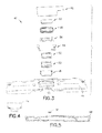
- Fig. 4 shows a front gasket 64 rather than use of the protective film 62.
- Fig. 5 also shows a microphone seal 66 and a printed circuit board (PCB) gasket 68 which could be used with the housing component 46.
- the housing component 46 such as made of molded plastic for example, is configured to have the other components attached thereto, such as including the printed circuit board 21 for example, to close the back cavity of the speaker box.
- the housing component 46 helps to form a speaker box which is located inside the housing 12.
- a same or similar cavity structure provided by the speaker box may be designed inside an electronic device where the electronic device also comprises a speaker transducer so that such cavity structure can be acoustically coupled to the speaker transducer.
- the apparatus could be a standalone speaker box, so that it could be placed inside the electronic device, or alternatively the apparatus may have such a cavity arrangement created inside the electronic device without accommodating any removable/attachable speaker box.
- the housing could be a speaker box, but such air space could be formed by different sections of the electronic device. Therefore, the housing 12 of the electronic apparatus 10 could form such cavity; entirely or at least partially.
- the housing component 46 has a receiving area 70 which is configured to receive the components 48-60.
- the housing component 46 is a one-piece member having integrally formed cavities 72, 74 which, along with an area directly under the transducer, form the back cavity for the speaker. In this example the two cavities 72, 74 are separated by the area directly under the sound transducer.
- the upstanding ribs or walls 76 surrounding the cavities 72, 74 are attached to another component, such as the PCB 21 as shown in Fig. 6A for example, to close the cavities 72, 74.
- the PCB may function as a housing member to form the back cavity with the housing component 46.
- the housing member 46 could be used with the housing member 46 to close the back cavity, or the housing member could provide the closed back cavity itself as a one piece member.
- the components 48-62 close off the aperture into the receiving area 70.
- the cavities 72, 74 form a sealed air space to function as the back cavity for the speaker.
- Features as described herein comprise providing one or more dividing structures (walls) 78, 79 having one or more apertures 80, 81 in the cavities 72, 74.
- Fig. 7 shows the housing member 46 without the dividing structures 78, 79.
- the cavities 72, 74 for the back cavity have a relatively simple generally block shape.
- the back cavity formed by the relatively simple, block shaped cavities 72, 74 provides a concentrated area, but would still be elongated enough to cause higher modes.
- the dividing structures are added to thereby provide a compact shape without elongated parts to provide better audio performance than a back cavity having an elongated shape.
- the first dividing structure 78 is a straight wall with a plurality of the apertures 80 therethrough.
- the first dividing structure 78 in the first cavity 72 because of the apertures 80, has a general grid or lattice shape.
- the ends or surfaces 82 of the dividing structure 78 are at the same plane as the ends of the walls 76.
- the surfaces 82 may be sealed onto the PCB with the walls 76. This is illustrated by Fig. 6A .
- a little gap may be provided between 82 and the PCB in order to cause a small leak; which usually has the effect of providing some acoustic damping.
- Pressure waves must travel through the apertures 80 in order to travel between the two cavity sections 72a, 72b of the cavity 72.
- the cavity sections 72a, 72b form two adjacent air mass holding sections of the back cavity.
- the size, location and shape of the apertures 80 may be selected so as to provide a tuning function, so as to attenuate and/or shift the modes to have a less detrimental effect on the frequency response, sound quality and loudspeaker lifetime.
- the second dividing structure 79 has two straight walls 84 forming a conduit therebetween by the aperture 81.
- the conduit may be considered a tuned pipe, or port or channel.
- the ends or surfaces 86 of the dividing structure 79 are at the same plane as the ends of the walls 76. Thus, the surfaces 86 may be sealed onto the PCB with the walls 76.
- the cavity sections 74a, 74b are still at the same plane as the ends of the walls 76.
- Pressure waves must travel through the aperture 81 in order to travel between the two cavity sections 74a, 74b of the cavity 74.
- the two cavity sections 74a, 74b form two adjacent air mass holding sections of the back cavity.
- the size, location and shape of the aperture 81 may be selected so as to provide a tuning function, so as to attenuate and/or shift the modes to have a less detrimental effect on the frequency response, sound quality and loudspeaker lifetime.
- the length of each half 72, 74 of the back cavity is about 24 mm, and has a width of about 9 mm.
- the ratio of length to width is about 2.67:1 or about 37.5%.
- the ratio may be about 4:1, or 3:1, or less.
- the height in this example is about 2.5 mm. The dimensions may vary along the length of the cavity.
- the first divider 78 has three slots 80, each may have the same height as the cavity (perhaps with a slight gap for dampening as mentioned above), with a width of about 0.6 mm, and a length (in air flow direction) of about 0.9 mm.
- the second divider 79 is, in effect, a rectangular tube having again the same height as the cavity, a width of about 0.8 mm, and a physical length of about 4.5 mm (the effective acoustical length is perhaps 8 mm, because of the walls close to the ends of the tube).
- the total acoustic volumes for the respective cavities are:
- the size of the section 72a relative to the size of the section 72b is about 50 percent or smaller, but it may be greater.
- the size of the section 74a relative to the size of the section 74b is about 50 percent or smaller, but it may be greater.
- the slots and wall locations could also be different as long as they still work for the given case.
- the sections 72a, 72b and 74a, 74b are all located in a same plane, side-by-side, and not stacked one on top of the other. In an alternate example the tube may also be shorter than the cavity in order to provide a small gap for damping.
- the angles 88, 89 of the dividing structures may be varied (or other shapes provided) to tune the reflections and pressure flows. The angle typically has only a negligible or non-existent effect on reflections; when dimensions are as small as here. However, the structures may be angled such as to merely avoid injection gates in the mold chamber, and components on the PWB for example.
- a tuned pipe effect is provided by the addition of the dividing structures, as a tuned expansion chamber, while still keeping the general block shape of the back chamber shown in Fig. 6 .
- a wall and aperture may be provided just to slightly shift a mode (from the loudspeaker's point of view) to a less risky frequency, to avoid failures of, for example, lead wires.
- a wall and aperture may be tuned to act as an acoustic low-pass filter that decouples an outer part of the cavity from an inner part of the cavity adjacent to the loudspeaker 42, above a given frequency, as a means of avoiding one or more higher modes.
- the end result may just be several weaker modes instead of one or a couple of strong modes, to help to flatten the frequency response and/or fit it inside given specification limits.
- the back cavity consists of two or more separate parts (branches), such as 72 and 74 for example, each of them may have its own dividing structure(s), or there may be two or more dividing structures in series; one after the other for example.
- the angles 88, 89 of the dividing structures and location of dividing structures might not be determined purely by acoustics, but may also have to be adjusted such as according to locations of other intervening components inside the back cavity and/or injection gates in the mold for example. In the example embodiment shown in Fig.
- the right side dividing structure 79 effectively consists of a tube (in order to produce a higher acoustic mass) whereas the left side dividing structure 78 instead has three slits (producing a lower acoustic mass and somewhat higher acoustic resistance in this case, with these dimensions).
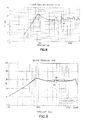
- the graph shows an example of a measured effect of having the above-mentioned dividing structures in the back cavity.
- Speaker frequency response at 1 V is shown.
- Line 90 shows the response for the back cavity shown in Fig. 7 which does not have the dividing structures.
- Line 92 shows the improved performance with the dividing structures 78, 79 in place in accordance with the example shown in Fig. 6 .
- the smaller difference between minimum and maximum sound pressure levels for the line 92 versus line 90, especially in the 4-6 kHz range, should be noted.
- damping elements may or may not be added.
- one or more dividing structures may be deliberately made slightly shorter than the surrounding walls in order to produce a small leakage acting as an additional acoustic resistance, or additional damping foam may be added to one or more dividing structures.
- An embodiment may have merely one dividing structure, two dividing structures, or more than two dividing structures.
- Fig. 9 frequency responses obtained from simulations for the back cavity of Fig. 6 (having two dividing structures) versus a back cavity having only one dividing structure is shown.
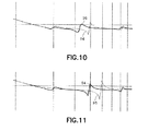
- Line 94 represents when one divider is used, and line 96 represents when two dividers are used.
- Fig. 10 shows an enlarged view of the lines 94, 96 between 1000-8000 Hz.
- frequency responses obtained from simulations for the back cavity having only one dividing structure is shown by line 94, and line 98 represents when no dividers are used as in the back cavity of Fig. 7 .
- a speaker will ordinarily be designed to fit within certain upper and lower speaker limits 100, 102 of frequency response.
- Fig. 12 shows samples of speaker frequency response at 700 mW for using the back cavity shown in Fig. 7 which does not have any dividing structures in the back cavity. As can be seen, some of the frequencies of the samples 104 exceed the limits for the speaker. By exceeding the limits, this results in reduced frequency response, sound quality and perhaps loudspeaker lifetime.
- Fig. 13 the same limits are shown for the same speaker, but with use of the back cavity having the dividing structures of Fig. 6 .
- the frequency response of the new samples 104' has been changed to no longer exceed the limits 100, 102.
- Frequency response has been flattened and shifted from the response with no dividing structures ( Fig. 12 ) versus the response with two dividing structures ( Fig. 13 ).
- the overall shape (without the dividing structures) is still too elongated, but rather than having one strong mode, with the addition of the dividing structures provides several weaker modes.
- Inside the generally block shaped back cavity are one or more dividing structures with aperture(s) which have been tuned to change the frequency response of the speaker.
- the back cavity formed by the relatively simple, block shaped cavities 72, 74 provides a compact shape without elongated parts to provide better audio performance than a back cavity having an elongated shape.
- artifacts such as higher modes that result in peaks and dips in the frequency response of the IHF are avoided.
- problematic pronounced peaks and dips, which otherwise would reduce sound quality, are avoided, perceived sound quality is improved, and a likelihood of premature failure is reduced.
- a dividing structure decouples an outer part of the back cavity from an inner one at higher frequencies and, thus, effectively reduces the cavity size at higher frequencies, meaning that the cavity at higher frequencies effectively becomes more compact.
- the back cavity need not be coupled to ambient air through an acoustic opening(s).
- the other side of the loudspeaker need not be coupled to the ambient air through acoustic opening(s).
- the back cavity (which is divided by the added constrictions 78, 79) is not coupled to ambient air (except perhaps for a small pressure-equalizing leak that has no appreciable direct effect on the acoustic performance), and only one side of the loudspeaker is coupled to the ambient air.
- a substantially sealed back cavity acoustically coupled to a speaker component, wherein pre-determined dividing walls (or a tube structure) are able to smooth the frequency response by trying to eliminate the effect of unwanted notches. It could be considered that these dividing structures may be constructed for optimizing a tuned frequency response rather than a tuning of the frequency response based on the cavity, aperture combinations.
- An example apparatus 10 may comprise a sound transducer 42; and a housing 12 having the sound transducer connected thereto (or otherwise positioned, integrated, placed, located, provided with the housing), where the housing forms a substantially sealed air space back cavity with the sound transducer, where the housing comprises a one-piece housing member 46 including a first dividing structure 78 or 79 located in the back cavity to separate two adjacent air mass holding sections of the back cavity, where the dividing structure comprises at least one aperture to limit travel of pressure waves through the at least one aperture between the sections.
- the housing member may be a one-piece housing member with the first dividing structure integrally formed with the one-piece housing member at a first side of the one-piece housing member, where the two adjacent air mass holding sections are located at the first side of the one-piece housing member.
- the one-piece housing member may comprise a second dividing structure located in the back cavity to separate two other adjacent air mass holding sections of the back cavity.
- the first dividing structure may comprise a wall having a plurality of apertures therethrough.
- the first dividing structure may comprise two spaced elongate walls with an aperture therebetween forming an elongate tuned pipe area.
- the first dividing structure may comprise an angled elongate wall. A size of the two adjacent air mass holding sections relative to each other may be about 50 percent or greater.
- the apparatus may further comprise a printed circuit board 21 connected to a first side of the one-piece housing member to substantially seal the back cavity.
- the apparatus may further comprise a printed circuit board connected to the sound transducer; at least one processor connected to the printed circuit board; at least one memory connected to the printed circuit board; at least one electronic display connected to the printed circuit board; and at least one battery connected to the printed circuit board.
- the apparatus may further comprise means for smoothing frequency response of the sound transducer, where the means for smoothing frequency response comprises the first dividing structure.
- An example method may comprise providing a sound transducer; connecting a housing member to the sound transducer, where the housing member comprises a wall establishing a perimeter of a back cavity area for the sound transducer, where the wall forms the back cavity area on a single first side of the housing member, where the housing member comprises a first dividing structure located in the back cavity area separating two adjacent air mass holding sections of the back cavity area; and connecting the first side of the housing member to at least one second member to substantially close the back cavity area, where the wall and the first dividing structure attach to the at least one second member to form a substantially sealed air space back cavity with the sound transducer.
- the first dividing structure may be integrally formed with the housing member, and where the two adjacent air mass holding sections are located at a same exterior first side of the one-piece housing member.
- the housing member may comprise a second dividing structure located in the back cavity to separate two other adjacent air mass holding sections of the back cavity, where free ends of the first and second dividing structures are attached to the at least one second member.
- the first dividing structure may comprise a wall having a plurality of apertures therethrough, where a free end of the wall is attached to the at least one second member.
- the first dividing structure may comprise two spaced elongate walls with an aperture therebetween forming an elongate tuned pipe area, where free ends of the two walls are attached to the at least one second member.
- the first dividing structure may comprise an angled elongate wall forming an angled joint between the two air mass holding sections.
- a size of the two adjacent air mass holding sections relative to each other, after the housing member is attached to the at least one second member, may be about 50 percent or greater.
- the two air mass holding sections of the back cavity may be located in a same plane along a first side of the housing member, where the first side is attached to the at least one second member.
- the at least one second member may comprise a printed circuit board connected to a first side of the one-piece housing member to substantially seal the back cavity area.
Landscapes
- Engineering & Computer Science (AREA)
- Signal Processing (AREA)
- Physics & Mathematics (AREA)
- Acoustics & Sound (AREA)
- Health & Medical Sciences (AREA)
- Otolaryngology (AREA)
- Obtaining Desirable Characteristics In Audible-Bandwidth Transducers (AREA)
- Details Of Audible-Bandwidth Transducers (AREA)
Abstract
Description
- The exemplary and non-limiting embodiments relate generally to a sound transducer and, more particularly, to a back cavity for a sound transducer.
- A speaker in a portable electronic device, such as a mobile phone for example, often has a back cavity for acoustic purposes.
- The following summary is merely intended to be exemplary. The summary is not intended to limit the scope of the claims.
- In accordance with one aspect, an example embodiment is provided in an apparatus including a sound transducer; and a housing having the sound transducer connected thereto. The housing forms a substantially sealed air space back cavity acoustically coupled to the sound transducer. The housing includes a housing member having a first dividing structure located in the back cavity to connect two adjacent air mass sections of the back cavity, where the dividing structure includes at least one aperture to permit travel of sound waves through the at least one aperture between the air mass sections.
- In accordance with another aspect, an example method comprises providing a sound transducer; connecting a housing member to the sound transducer, where the housing member comprises a wall establishing a perimeter of a back cavity area for the sound transducer, where the wall forms the back cavity area on a single first side of the housing member, where the housing member comprises a first dividing structure located in the back cavity area connecting two adjacent air mass sections of the back cavity area; and connecting the first side of the housing member to at least one second member to substantially close the back cavity area, where the wall and the first dividing structure attach to the at least one second member to form a substantially sealed air space back cavity acoustically coupled to the sound transducer.
- The foregoing aspects and other features are explained in the following description, taken in connection with the accompanying drawings, wherein:
-
Fig. 1 is a front view of an example embodiment of an apparatus comprising features as described herein; -
Fig. 2 is a rear view of the apparatus shown inFig. 1 ; -
Fig. 3 is an exploded perspective view of components of the speaker and its housing member shown inFig. 2 ; -
Fig. 4 is a perspective view of an alternate embodiment of one of the components shown inFig. 3 ; -
Fig. 5 is a perspective view of other possible components of the apparatus shown inFigs. 1-3 ; -
Fig. 6 is a bottom plan view of the housing member shown inFig. 3 ; -
Fig. 6A is a schematic cross section view of the speaker and housing member shown inFigs. 3 and6 attached to a printed circuit board of the apparatus shown inFigs. 1-2 ; -
Fig. 7 is a bottom plan view of the housing member shown inFig. 6 , but without the dividing structures; -
Fig. 8 is a graph of speaker frequency response at 1 Volt for use with the housing member shown inFig. 6 versus the housing member shown inFig. 7 ; -
Fig. 9 is a graph of simulated speaker frequency response at 700 mV for use with the housing member shown inFig. 6 versus a housing member similar to that shown inFig. 6 but having only one dividing structure rather than two dividing structures; -
Fig. 10 is an enlarged view of a portion of the graph shown inFig. 9 ; -
Fig. 11 is a view as inFig. 10 of simulated speaker frequency response at 700 mV with use of the housing member shown inFig. 7 versus a housing member at inFig. 6 but having only one dividing structure; -
Fig. 12 is a graph illustrating design limits for a speaker and sample speaker frequency responses for a speaker using the housing member shown inFig. 7 ; and -
Fig. 13 is a graph similar tofig. 12 illustrating the design limits and sample speaker frequency responses for a speaker using the housing member shown inFig. 6 . - Referring to
Fig. 1 , there is shown a front view of anapparatus 10 incorporating features of an example embodiment. Although the features will be described with reference to the example embodiments shown in the drawings, it should be understood that features can be embodied in many alternate forms of embodiments. In addition, any suitable size, shape or type of elements or materials could be used. - The
apparatus 10 may be a hand-held portable apparatus, such as a communications device which includes a telephone application for example. In the example shown theapparatus 10 is a smartphone which includes a camera and a camera application. Theapparatus 10 may additionally or alternatively comprise an Internet browser application, a video recorder application, a music player and recorder application, an email application, a navigation application, a gaming application, and/or any other suitable electronic device application. In an alternate example embodiment the apparatus might not be a smartphone. - Referring also to
Fig. 2 , theapparatus 10, in this example embodiment, comprises ahousing 12, atouchscreen 14, areceiver 16, atransmitter 18, acontroller 20, arechargeable battery 26 and acamera 30. However, all of these features are not necessary to implement the features described below. Thecontroller 20 may include at least oneprocessor 22, at least onememory 24, andsoftware 28. The electronic circuitry inside thehousing 12 may comprise at least one printed wiring board (PWB) 21 having components such as thecontroller 20 thereon. Thereceiver 16 andtransmitter 18 form a primary communications system to allow theapparatus 10 to communicate with a wireless telephone system, such as a mobile telephone base station for example. - In this example, the
apparatus 10 includes thecamera 30 which is located at therear side 13 of the apparatus, afront camera 32, anLED 34, and aflash system 36. TheLED 34 and theflash system 36 are also visible at the rear side of the apparatus, and are provided for thecamera 30. Thecameras LED 34 and theflash system 36 are connected to thecontroller 20 such that thecontroller 20 may control their operation. In an alternate example embodiment the rear side may comprise more than one camera, and/or the front side could comprise more than one camera. Theapparatus 10 includes a sound transducer provided as amicrophone 38. In an alternate example the apparatus may comprise more than one microphone. Theapparatus 10 includes a sound transducer provided as anearpiece 40, and a sound transducer provided as aspeaker 42. More or less than one speaker may be provided. - Features as described herein relate to audio reproduction, such as in a mobile communication device for example. More specifically, features may relate to an enclosure for an integrated hands-free (IHF) loudspeaker, such as the
speaker 42 for example. Such a loudspeaker most commonly has one side enclosed in a sealed air space, hereafter known as the back cavity, while the other side of the loudspeaker is coupled to a sound outlet in the outer cover of the mobile communication device. In the embodiment shown inFig. 2 , theback cover 13 comprisessound holes 44 for thespeaker 42. However, in alternate embodiments the sound holes and speaker could be located at any suitable location on the apparatus. - Mobile devices usually have severely constrained spaces inside them. In spite of this, a back cavity must be arranged for the IHF loudspeaker. This means that the back cavity often has to have an elongated shape. For good audio performance, the opposite (i.e. a compact shape without elongated parts) is better. Elongated shapes of such cavities usually cause artifacts such as higher modes that result in peaks and dips in the frequency response of the IHF. Pronounced peaks and dips are problematic not only because they reduce sound quality, but also because they may keep the IHF from passing audio reproduction requirements, and furthermore because they may lead to physical failure of the speaker. Physical failure can happen such as if a mode happens to coincide with a vibration mode in the lead wires of the loudspeaker for example. Even if the frequency response of an IHF does fit inside given specification limits, high peaks and dips are undesirable as they leave less margin for inevitable variation in performance due to tolerances.
- Referring also to
Fig. 3 , in this example thespeaker 42 is provided in the form with a speaker box. In particular, for this example thespeaker 42 comprises ahousing component 46, ayoke 48, amagnet 50, aplate 52,metal inserts 54, aelectromagnetic coil 56, amembrane 58, a done 60 and a liner orprotective film 62. This is merely an example of some of the components. In alternate embodiments other types of components may be used. For example,Fig. 4 shows afront gasket 64 rather than use of theprotective film 62.Fig. 5 also shows amicrophone seal 66 and a printed circuit board (PCB)gasket 68 which could be used with thehousing component 46. Thehousing component 46, such as made of molded plastic for example, is configured to have the other components attached thereto, such as including the printedcircuit board 21 for example, to close the back cavity of the speaker box. - In this example the
housing component 46 helps to form a speaker box which is located inside thehousing 12. In an alternate example a same or similar cavity structure provided by the speaker box may be designed inside an electronic device where the electronic device also comprises a speaker transducer so that such cavity structure can be acoustically coupled to the speaker transducer. In this regard the apparatus could be a standalone speaker box, so that it could be placed inside the electronic device, or alternatively the apparatus may have such a cavity arrangement created inside the electronic device without accommodating any removable/attachable speaker box. Basically the housing could be a speaker box, but such air space could be formed by different sections of the electronic device. Therefore, thehousing 12 of theelectronic apparatus 10 could form such cavity; entirely or at least partially. - Referring also to
Fig. 6 , the opposite side of thehousing component 46 is shown. Thehousing component 46 has a receivingarea 70 which is configured to receive the components 48-60. Thehousing component 46 is a one-piece member having integrally formedcavities cavities walls 76 surrounding thecavities PCB 21 as shown inFig. 6A for example, to close thecavities housing component 46. In an alternate example, another member(s) could be used with thehousing member 46 to close the back cavity, or the housing member could provide the closed back cavity itself as a one piece member. The components 48-62 close off the aperture into the receivingarea 70. Thus, thecavities more apertures cavities Fig. 7 shows thehousing member 46 without the dividingstructures cavities cavities - In this example embodiment, the
first dividing structure 78 is a straight wall with a plurality of theapertures 80 therethrough. Thefirst dividing structure 78 in thefirst cavity 72, because of theapertures 80, has a general grid or lattice shape. The ends or surfaces 82 of the dividingstructure 78 are at the same plane as the ends of thewalls 76. Thus, thesurfaces 82 may be sealed onto the PCB with thewalls 76. This is illustrated byFig. 6A . In an alternate example, a little gap may be provided between 82 and the PCB in order to cause a small leak; which usually has the effect of providing some acoustic damping. Pressure waves must travel through theapertures 80 in order to travel between the twocavity sections cavity 72. Thecavity sections apertures 80 may be selected so as to provide a tuning function, so as to attenuate and/or shift the modes to have a less detrimental effect on the frequency response, sound quality and loudspeaker lifetime. - In this example embodiment, the
second dividing structure 79 has twostraight walls 84 forming a conduit therebetween by theaperture 81. The conduit may be considered a tuned pipe, or port or channel. The ends or surfaces 86 of the dividingstructure 79 are at the same plane as the ends of thewalls 76. Thus, thesurfaces 86 may be sealed onto the PCB with thewalls 76. In the alternate example where a small gap is provided between theends 86 and the PCB, thecavity sections walls 76. Pressure waves must travel through theaperture 81 in order to travel between the twocavity sections cavity 74. The twocavity sections aperture 81 may be selected so as to provide a tuning function, so as to attenuate and/or shift the modes to have a less detrimental effect on the frequency response, sound quality and loudspeaker lifetime. - In one example embodiment, the length of each
half first divider 78 has threeslots 80, each may have the same height as the cavity (perhaps with a slight gap for dampening as mentioned above), with a width of about 0.6 mm, and a length (in air flow direction) of about 0.9 mm. Thesecond divider 79 is, in effect, a rectangular tube having again the same height as the cavity, a width of about 0.8 mm, and a physical length of about 4.5 mm (the effective acoustical length is perhaps 8 mm, because of the walls close to the ends of the tube). In this example embodiment the total acoustic volumes for the respective cavities are: -
Cavity 72 having 3 slots = about 0.55 cm3, -
Cavity 74 having tube = about 0.43 cm3. - The size of the
section 72a relative to the size of thesection 72b is about 50 percent or smaller, but it may be greater. The size of thesection 74a relative to the size of thesection 74b is about 50 percent or smaller, but it may be greater. Please note that the specific specification numbers and dimensions given above these are merely for an example, and should not be considered as limiting. The slots and wall locations could also be different as long as they still work for the given case. Thesections - There is no principal difference between how a series of slots, or a single tube, work. Both produce an additional acoustic mass at the given location, and it may be tuned according to the cavity shape and volume. One must also consider what dimensions are achievable by molding plastic. The
angles 88, 89 of the dividing structures may be varied (or other shapes provided) to tune the reflections and pressure flows. The angle typically has only a negligible or non-existent effect on reflections; when dimensions are as small as here. However, the structures may be angled such as to merely avoid injection gates in the mold chamber, and components on the PWB for example. A tuned pipe effect is provided by the addition of the dividing structures, as a tuned expansion chamber, while still keeping the general block shape of the back chamber shown inFig. 6 . There are many possible ways to tune the dividing structures. In one example, a wall and aperture may be provided just to slightly shift a mode (from the loudspeaker's point of view) to a less risky frequency, to avoid failures of, for example, lead wires. In another example, a wall and aperture may be tuned to act as an acoustic low-pass filter that decouples an outer part of the cavity from an inner part of the cavity adjacent to theloudspeaker 42, above a given frequency, as a means of avoiding one or more higher modes. In yet another example, the end result may just be several weaker modes instead of one or a couple of strong modes, to help to flatten the frequency response and/or fit it inside given specification limits. - If the back cavity consists of two or more separate parts (branches), such as 72 and 74 for example, each of them may have its own dividing structure(s), or there may be two or more dividing structures in series; one after the other for example. The
angles 88, 89 of the dividing structures and location of dividing structures might not be determined purely by acoustics, but may also have to be adjusted such as according to locations of other intervening components inside the back cavity and/or injection gates in the mold for example. In the example embodiment shown inFig. 6 , the rightside dividing structure 79 effectively consists of a tube (in order to produce a higher acoustic mass) whereas the leftside dividing structure 78 instead has three slits (producing a lower acoustic mass and somewhat higher acoustic resistance in this case, with these dimensions). - Referring also to
Fig. 8 , the graph shows an example of a measured effect of having the above-mentioned dividing structures in the back cavity. Speaker frequency response at 1 V is shown.Line 90 shows the response for the back cavity shown inFig. 7 which does not have the dividing structures.Line 92 shows the improved performance with the dividingstructures Fig. 6 . The smaller difference between minimum and maximum sound pressure levels for theline 92 versusline 90, especially in the 4-6 kHz range, should be noted. - To this implementation, further damping elements may or may not be added. For example, one or more dividing structures may be deliberately made slightly shorter than the surrounding walls in order to produce a small leakage acting as an additional acoustic resistance, or additional damping foam may be added to one or more dividing structures.
- An embodiment may have merely one dividing structure, two dividing structures, or more than two dividing structures. Referring also to
Fig. 9 , frequency responses obtained from simulations for the back cavity ofFig. 6 (having two dividing structures) versus a back cavity having only one dividing structure is shown.Line 94 represents when one divider is used, andline 96 represents when two dividers are used.Fig. 10 shows an enlarged view of thelines Fig. 11 , frequency responses obtained from simulations for the back cavity having only one dividing structure is shown byline 94, andline 98 represents when no dividers are used as in the back cavity ofFig. 7 . These figures help to clarify the effect of one divider versus use of two dividers and versus when no dividers are used. - Referring also to
Fig. 12 , a speaker will ordinarily be designed to fit within certain upper and lower speaker limits 100, 102 of frequency response.Fig. 12 shows samples of speaker frequency response at 700 mW for using the back cavity shown inFig. 7 which does not have any dividing structures in the back cavity. As can be seen, some of the frequencies of thesamples 104 exceed the limits for the speaker. By exceeding the limits, this results in reduced frequency response, sound quality and perhaps loudspeaker lifetime. - Referring also to
Fig. 13 , the same limits are shown for the same speaker, but with use of the back cavity having the dividing structures ofFig. 6 . As can be seen, the frequency response of the new samples 104' has been changed to no longer exceed thelimits Fig. 12 ) versus the response with two dividing structures (Fig. 13 ). Compare also line 98 (no dividing structures) to line 94 (one dividing structure) to line 96 (two dividing structures). Features as described herein allow for a compact back cavity having a relatively simple, generally block shape without elongated parts. The overall shape (without the dividing structures) is still too elongated, but rather than having one strong mode, with the addition of the dividing structures provides several weaker modes. Inside the generally block shaped back cavity are one or more dividing structures with aperture(s) which have been tuned to change the frequency response of the speaker. - For audio performance, the back cavity formed by the relatively simple, block shaped
cavities - With features as described herein, the back cavity need not be coupled to ambient air through an acoustic opening(s). Also, the other side of the loudspeaker need not be coupled to the ambient air through acoustic opening(s). In an example embodiment, the back cavity (which is divided by the added
constrictions 78, 79) is not coupled to ambient air (except perhaps for a small pressure-equalizing leak that has no appreciable direct effect on the acoustic performance), and only one side of the loudspeaker is coupled to the ambient air. - In an example embodiment, there may be provided a substantially sealed back cavity, acoustically coupled to a speaker component, wherein pre-determined dividing walls (or a tube structure) are able to smooth the frequency response by trying to eliminate the effect of unwanted notches. It could be considered that these dividing structures may be constructed for optimizing a tuned frequency response rather than a tuning of the frequency response based on the cavity, aperture combinations.
- An
example apparatus 10 may comprise asound transducer 42; and ahousing 12 having the sound transducer connected thereto (or otherwise positioned, integrated, placed, located, provided with the housing), where the housing forms a substantially sealed air space back cavity with the sound transducer, where the housing comprises a one-piece housing member 46 including afirst dividing structure - The housing member may be a one-piece housing member with the first dividing structure integrally formed with the one-piece housing member at a first side of the one-piece housing member, where the two adjacent air mass holding sections are located at the first side of the one-piece housing member. The one-piece housing member may comprise a second dividing structure located in the back cavity to separate two other adjacent air mass holding sections of the back cavity. The first dividing structure may comprise a wall having a plurality of apertures therethrough. The first dividing structure may comprise two spaced elongate walls with an aperture therebetween forming an elongate tuned pipe area. The first dividing structure may comprise an angled elongate wall. A size of the two adjacent air mass holding sections relative to each other may be about 50 percent or greater. Two air mass holding sections of the back cavity may be located in a same plane along a
first side 76 of the one-piece housing member. The apparatus may further comprise a printedcircuit board 21 connected to a first side of the one-piece housing member to substantially seal the back cavity. The apparatus may further comprise a printed circuit board connected to the sound transducer; at least one processor connected to the printed circuit board; at least one memory connected to the printed circuit board; at least one electronic display connected to the printed circuit board; and at least one battery connected to the printed circuit board. The apparatus may further comprise means for smoothing frequency response of the sound transducer, where the means for smoothing frequency response comprises the first dividing structure. - An example method may comprise providing a sound transducer; connecting a housing member to the sound transducer, where the housing member comprises a wall establishing a perimeter of a back cavity area for the sound transducer, where the wall forms the back cavity area on a single first side of the housing member, where the housing member comprises a first dividing structure located in the back cavity area separating two adjacent air mass holding sections of the back cavity area; and connecting the first side of the housing member to at least one second member to substantially close the back cavity area, where the wall and the first dividing structure attach to the at least one second member to form a substantially sealed air space back cavity with the sound transducer.
- The first dividing structure may be integrally formed with the housing member, and where the two adjacent air mass holding sections are located at a same exterior first side of the one-piece housing member. The housing member may comprise a second dividing structure located in the back cavity to separate two other adjacent air mass holding sections of the back cavity, where free ends of the first and second dividing structures are attached to the at least one second member. The first dividing structure may comprise a wall having a plurality of apertures therethrough, where a free end of the wall is attached to the at least one second member. The first dividing structure may comprise two spaced elongate walls with an aperture therebetween forming an elongate tuned pipe area, where free ends of the two walls are attached to the at least one second member. The first dividing structure may comprise an angled elongate wall forming an angled joint between the two air mass holding sections. A size of the two adjacent air mass holding sections relative to each other, after the housing member is attached to the at least one second member, may be about 50 percent or greater. The two air mass holding sections of the back cavity may be located in a same plane along a first side of the housing member, where the first side is attached to the at least one second member. The at least one second member may comprise a printed circuit board connected to a first side of the one-piece housing member to substantially seal the back cavity area.
- It should be understood that the foregoing description is only illustrative. Various alternatives and modifications can be devised by those skilled in the art. For example, features recited in the various dependent claims could be combined with each other in any suitable combination(s). In addition, features from different embodiments described above could be selectively combined into a new embodiment. Accordingly, the description is intended to embrace all such alternatives, modifications and variances which fall within the scope of the appended claims.
Claims (15)
- An apparatus comprising:a sound transducer; anda housing having the sound transducer connected thereto,where the housing forms a substantially sealed air space back cavity acoustically coupled to the sound transducer,where the housing comprises a housing member including a first dividing structure located in the back cavity to connect two adjacent air mass holding sections of the back cavity, where the dividing structure comprises at least one aperture to permit travel of sound waves through the at least one aperture between the air mass holding sections.
- The apparatus as claimed in claim 1, wherein the housing member is a one-piece housing member having the first dividing structure integrally formed with the one-piece housing member at a first side of the one-piece housing member, where the two adjacent air mass holding sections are located at the first side of the one-piece housing member.
- The apparatus as in any of claim 1 or 2, wherein the one-piece housing member comprises a second dividing structure located in the back cavity to connect two other adjacent air mass holding sections of the back cavity.
- The apparatus as claimed in any preceding claim, where the first dividing structure comprises a wall having a plurality of apertures therethrough.
- The apparatus as claimed in any of claims 1 to 3, wherein the first dividing structure comprises one of:two spaced elongate walls with an aperture therebetween forming an elongate tuned conduit area; andan angled elongate wall.
- The apparatus as claimed in any preceding claim, wherein a size of the two adjacent air mass holding sections relative to each other is about 50 percent or less.
- The apparatus as claimed in any preceding claim, wherein the two air mass holding sections of the back cavity are located in a same plane along a first side of the housing member.
- The apparatus as claimed in any preceding claim, further comprising:a printed circuit board connected to the sound transducer;at least one processor connected to the printed circuit board;at least one memory connected to the printed circuit board;at least one electronic display connected to the printed circuit board; andat least one battery connected to the printed circuit board.
- The apparatus as claimed in any preceding claim, further comprising means for smoothing frequency response of the sound transducer, where the means for smoothing frequency response comprises the first dividing structure.
- A method comprising:providing a sound transducer;connecting a housing member to the sound transducer, where the housing member comprises a wall establishing a perimeter of a back cavity area for the sound transducer,where the wall forms the back cavity area on a single first side of the housing member, where the housing member comprises a first dividing structure located in the back cavity area connecting two adjacent air mass sections of the back cavity area; andconnecting the first side of the housing member to at least one second member to substantially close the back cavity area, where the wall and the first dividing structure attach to the at least one second member to form a substantially sealed air space back cavity acoustically coupled to the sound transducer.
- The method as claimed in claim 10, wherein the first dividing structure is integrally formed with the housing member, and where the two adjacent air mass sections are located at a same exterior first side of the housing member.
- The method as claimed in any of claim 10 or 11, wherein the housing member comprises a second dividing structure located in the back cavity to connect two other adjacent air mass sections of the back cavity, where free ends of the first and second dividing structures are attached to the at least one second member.
- The method as claimed in any preceding claim, wherein the first dividing structure comprises a wall having a plurality of apertures therethrough, where a free end of the wall is attached to the at least one second member.
- The method as claimed in any of claims 10 to 12, wherein the first dividing structure comprises one of:two spaced elongate walls with an aperture therebetween forming an elongate tuned conduit area, where free ends of the two walls are attached to the at least one second member; andan angled elongate wall forming an angled joint between the two air mass sections.
- The method as claimed in any preceding claim, wherein the two air mass sections of the back cavity are located in a same plane along a first side of the housing member, where the first side is attached to the at least one second member.
Priority Applications (1)
| Application Number | Priority Date | Filing Date | Title |
|---|---|---|---|
| EP15194872.6A EP3021560B1 (en) | 2013-10-22 | 2014-10-13 | Speaker back cavity |
Applications Claiming Priority (1)
| Application Number | Priority Date | Filing Date | Title |
|---|---|---|---|
| US14/059,975 US9386134B2 (en) | 2013-10-22 | 2013-10-22 | Speaker back cavity |
Related Child Applications (2)
| Application Number | Title | Priority Date | Filing Date |
|---|---|---|---|
| EP15194872.6A Division EP3021560B1 (en) | 2013-10-22 | 2014-10-13 | Speaker back cavity |
| EP15194872.6A Division-Into EP3021560B1 (en) | 2013-10-22 | 2014-10-13 | Speaker back cavity |
Publications (2)
| Publication Number | Publication Date |
|---|---|
| EP2866424A1 true EP2866424A1 (en) | 2015-04-29 |
| EP2866424B1 EP2866424B1 (en) | 2017-11-22 |
Family
ID=51687951
Family Applications (2)
| Application Number | Title | Priority Date | Filing Date |
|---|---|---|---|
| EP14188583.0A Active EP2866424B1 (en) | 2013-10-22 | 2014-10-13 | Speaker back cavity |
| EP15194872.6A Active EP3021560B1 (en) | 2013-10-22 | 2014-10-13 | Speaker back cavity |
Family Applications After (1)
| Application Number | Title | Priority Date | Filing Date |
|---|---|---|---|
| EP15194872.6A Active EP3021560B1 (en) | 2013-10-22 | 2014-10-13 | Speaker back cavity |
Country Status (2)
| Country | Link |
|---|---|
| US (3) | US9386134B2 (en) |
| EP (2) | EP2866424B1 (en) |
Families Citing this family (9)
| Publication number | Priority date | Publication date | Assignee | Title |
|---|---|---|---|---|
| KR102384503B1 (en) * | 2015-08-11 | 2022-04-12 | 삼성전자주식회사 | Slim-type portable electronic device |
| CN108307285A (en) * | 2017-12-12 | 2018-07-20 | 努比亚技术有限公司 | Mike's seal assembly and mobile terminal and its assembly method for mobile terminal |
| CN108235195A (en) * | 2018-01-05 | 2018-06-29 | 瑞声科技(新加坡)有限公司 | Loudspeaker enclosure |
| CN108430014B (en) * | 2018-02-11 | 2019-07-05 | 瑞声科技(新加坡)有限公司 | speaker box |
| JP7180671B2 (en) * | 2018-05-31 | 2022-11-30 | 株式会社ソシオネクスト | In-vehicle device |
| WO2021134292A1 (en) * | 2019-12-30 | 2021-07-08 | 瑞声声学科技(深圳)有限公司 | Loudspeaker box and electronic device applying same |
| US11659677B2 (en) | 2020-09-21 | 2023-05-23 | Google Llc | Structural midframe for an electronic device having a camera and a speaker |
| US11265632B1 (en) | 2021-01-21 | 2022-03-01 | Google Llc | Speaker-integration system for an electronic device, and associated devices and systems |
| CN113099014B (en) * | 2021-04-26 | 2023-03-21 | 维沃移动通信有限公司 | Electronic device |
Citations (3)
| Publication number | Priority date | Publication date | Assignee | Title |
|---|---|---|---|---|
| EP1389032A2 (en) * | 2002-07-29 | 2004-02-11 | Hosiden Corporation | Receiver unit |
| US20040142731A1 (en) * | 2003-01-21 | 2004-07-22 | San-Chi Ho | Speaker module design |
| US20080130931A1 (en) * | 2006-11-30 | 2008-06-05 | Motorola, Inc. | Attachable external acoustic chamber for a mobile device |
Family Cites Families (15)
| Publication number | Priority date | Publication date | Assignee | Title |
|---|---|---|---|---|
| JPH03130700U (en) * | 1990-04-10 | 1991-12-27 | ||
| JP3144230B2 (en) | 1994-09-01 | 2001-03-12 | 松下電器産業株式会社 | Bass reproduction speaker |
| JP3946117B2 (en) | 2002-10-07 | 2007-07-18 | シチズン電子株式会社 | Sound structure |
| TWI244303B (en) * | 2004-02-03 | 2005-11-21 | Benq Corp | Resonation chambers within a cell phone |
| US7409058B2 (en) * | 2004-06-01 | 2008-08-05 | Research In Motion Limited | Display cover for a communication device |
| US7280666B2 (en) | 2004-10-26 | 2007-10-09 | Guyot Nicolas E | Moveable device component with acoustic porting |
| KR101196953B1 (en) | 2005-10-06 | 2012-11-05 | 삼성전자주식회사 | Speaker device for portable terminal |
| US7578368B2 (en) | 2007-03-07 | 2009-08-25 | Foxconn Technology Co., Ltd. | Speaker set for electronic product |
| CN101500185A (en) | 2008-01-30 | 2009-08-05 | 深圳富泰宏精密工业有限公司 | Loudspeaker assembly |
| US8238595B2 (en) * | 2009-01-07 | 2012-08-07 | Hewlett-Packard Development Company, L.P. | Speaker component for a portable electronic device |
| US8913738B2 (en) * | 2009-06-30 | 2014-12-16 | Nokia Corporation | Apparatus with wideband earpiece response |
| CN102045625B (en) | 2010-09-20 | 2013-09-18 | 瑞声声学科技(深圳)有限公司 | Magnetic loudspeaker |
| JP2013120958A (en) | 2011-12-06 | 2013-06-17 | Nec Casio Mobile Communications Ltd | Mobile type electronic apparatus |
| CN202979074U (en) | 2013-01-09 | 2013-06-05 | 广东欧珀移动通信有限公司 | Sound cavity sealing structure of mobile phone microphone |
| CN103220608B (en) * | 2013-04-16 | 2016-08-24 | 歌尔声学股份有限公司 | Speaker module |
-
2013
- 2013-10-22 US US14/059,975 patent/US9386134B2/en active Active
-
2014
- 2014-10-13 EP EP14188583.0A patent/EP2866424B1/en active Active
- 2014-10-13 EP EP15194872.6A patent/EP3021560B1/en active Active
-
2016
- 2016-03-22 US US15/077,073 patent/US9800969B2/en active Active
-
2017
- 2017-04-05 US US15/479,396 patent/US10027784B2/en active Active
Patent Citations (3)
| Publication number | Priority date | Publication date | Assignee | Title |
|---|---|---|---|---|
| EP1389032A2 (en) * | 2002-07-29 | 2004-02-11 | Hosiden Corporation | Receiver unit |
| US20040142731A1 (en) * | 2003-01-21 | 2004-07-22 | San-Chi Ho | Speaker module design |
| US20080130931A1 (en) * | 2006-11-30 | 2008-06-05 | Motorola, Inc. | Attachable external acoustic chamber for a mobile device |
Also Published As
| Publication number | Publication date |
|---|---|
| US20150110327A1 (en) | 2015-04-23 |
| US20170208162A1 (en) | 2017-07-20 |
| EP3021560B1 (en) | 2023-06-28 |
| US9386134B2 (en) | 2016-07-05 |
| US9800969B2 (en) | 2017-10-24 |
| US20160205465A1 (en) | 2016-07-14 |
| EP2866424B1 (en) | 2017-11-22 |
| US10027784B2 (en) | 2018-07-17 |
| EP3021560A1 (en) | 2016-05-18 |
Similar Documents
| Publication | Publication Date | Title |
|---|---|---|
| US9800969B2 (en) | Speaker back cavity | |
| US10085086B2 (en) | Resonance damping for audio transducer systems | |
| US10397719B2 (en) | Ported headphones and related methods | |
| KR101691362B1 (en) | Ultrathin loudspeaker module | |
| CN102687489B (en) | Electronic apparatus | |
| US11317195B2 (en) | Miniature loudspeaker module | |
| US10567858B2 (en) | Loudspeaker module and terminal device | |
| CN101170311B (en) | Mobile communication device | |
| EP2278777A2 (en) | Apparatus with adjustable speaker arrangement | |
| US11064287B2 (en) | Speaker | |
| EP4246999A1 (en) | Audio device | |
| CN1748440A (en) | Mobile device with improved acoustic porting | |
| CN104685902B (en) | Acoustic back cavity system for sound transducer | |
| US11166092B2 (en) | Head phone structure having two chambers | |
| US9065892B2 (en) | Receiver and mobile communication terminal including the receiver | |
| CN210016620U (en) | Loudspeaker box | |
| CN209964290U (en) | Loudspeaker box | |
| CN209823927U (en) | Loudspeaker box | |
| CN201750522U (en) | Loudspeaker system | |
| TW200926863A (en) | Speaker assembly |
Legal Events
| Date | Code | Title | Description |
|---|---|---|---|
| PUAI | Public reference made under article 153(3) epc to a published international application that has entered the european phase |
Free format text: ORIGINAL CODE: 0009012 |
|
| 17P | Request for examination filed |
Effective date: 20141013 |
|
| AK | Designated contracting states |
Kind code of ref document: A1 Designated state(s): AL AT BE BG CH CY CZ DE DK EE ES FI FR GB GR HR HU IE IS IT LI LT LU LV MC MK MT NL NO PL PT RO RS SE SI SK SM TR |
|
| AX | Request for extension of the european patent |
Extension state: BA ME |
|
| RAP1 | Party data changed (applicant data changed or rights of an application transferred) |
Owner name: NOKIA TECHNOLOGIES OY |
|
| R17P | Request for examination filed (corrected) |
Effective date: 20151029 |
|
| RBV | Designated contracting states (corrected) |
Designated state(s): AL AT BE BG CH CY CZ DE DK EE ES FI FR GB GR HR HU IE IS IT LI LT LU LV MC MK MT NL NO PL PT RO RS SE SI SK SM TR |
|
| GRAP | Despatch of communication of intention to grant a patent |
Free format text: ORIGINAL CODE: EPIDOSNIGR1 |
|
| INTG | Intention to grant announced |
Effective date: 20160623 |
|
| GRAJ | Information related to disapproval of communication of intention to grant by the applicant or resumption of examination proceedings by the epo deleted |
Free format text: ORIGINAL CODE: EPIDOSDIGR1 |
|
| STAA | Information on the status of an ep patent application or granted ep patent |
Free format text: STATUS: REQUEST FOR EXAMINATION WAS MADE |
|
| GRAP | Despatch of communication of intention to grant a patent |
Free format text: ORIGINAL CODE: EPIDOSNIGR1 |
|
| STAA | Information on the status of an ep patent application or granted ep patent |
Free format text: STATUS: GRANT OF PATENT IS INTENDED |
|
| INTC | Intention to grant announced (deleted) | ||
| INTG | Intention to grant announced |
Effective date: 20161130 |
|
| GRAJ | Information related to disapproval of communication of intention to grant by the applicant or resumption of examination proceedings by the epo deleted |
Free format text: ORIGINAL CODE: EPIDOSDIGR1 |
|
| STAA | Information on the status of an ep patent application or granted ep patent |
Free format text: STATUS: REQUEST FOR EXAMINATION WAS MADE |
|
| GRAP | Despatch of communication of intention to grant a patent |
Free format text: ORIGINAL CODE: EPIDOSNIGR1 |
|
| STAA | Information on the status of an ep patent application or granted ep patent |
Free format text: STATUS: GRANT OF PATENT IS INTENDED |
|
| INTC | Intention to grant announced (deleted) | ||
| INTG | Intention to grant announced |
Effective date: 20170508 |
|
| GRAS | Grant fee paid |
Free format text: ORIGINAL CODE: EPIDOSNIGR3 |
|
| GRAA | (expected) grant |
Free format text: ORIGINAL CODE: 0009210 |
|
| STAA | Information on the status of an ep patent application or granted ep patent |
Free format text: STATUS: THE PATENT HAS BEEN GRANTED |
|
| AK | Designated contracting states |
Kind code of ref document: B1 Designated state(s): AL AT BE BG CH CY CZ DE DK EE ES FI FR GB GR HR HU IE IS IT LI LT LU LV MC MK MT NL NO PL PT RO RS SE SI SK SM TR |
|
| REG | Reference to a national code |
Ref country code: GB Ref legal event code: FG4D |
|
| REG | Reference to a national code |
Ref country code: CH Ref legal event code: EP |
|
| REG | Reference to a national code |
Ref country code: IE Ref legal event code: FG4D |
|
| REG | Reference to a national code |
Ref country code: AT Ref legal event code: REF Ref document number: 949383 Country of ref document: AT Kind code of ref document: T Effective date: 20171215 |
|
| REG | Reference to a national code |
Ref country code: DE Ref legal event code: R096 Ref document number: 602014017490 Country of ref document: DE |
|
| REG | Reference to a national code |
Ref country code: NL Ref legal event code: FP |
|
| REG | Reference to a national code |
Ref country code: LT Ref legal event code: MG4D |
|
| REG | Reference to a national code |
Ref country code: AT Ref legal event code: MK05 Ref document number: 949383 Country of ref document: AT Kind code of ref document: T Effective date: 20171122 |
|
| PG25 | Lapsed in a contracting state [announced via postgrant information from national office to epo] |
Ref country code: FI Free format text: LAPSE BECAUSE OF FAILURE TO SUBMIT A TRANSLATION OF THE DESCRIPTION OR TO PAY THE FEE WITHIN THE PRESCRIBED TIME-LIMIT Effective date: 20171122 Ref country code: ES Free format text: LAPSE BECAUSE OF FAILURE TO SUBMIT A TRANSLATION OF THE DESCRIPTION OR TO PAY THE FEE WITHIN THE PRESCRIBED TIME-LIMIT Effective date: 20171122 Ref country code: SE Free format text: LAPSE BECAUSE OF FAILURE TO SUBMIT A TRANSLATION OF THE DESCRIPTION OR TO PAY THE FEE WITHIN THE PRESCRIBED TIME-LIMIT Effective date: 20171122 Ref country code: NO Free format text: LAPSE BECAUSE OF FAILURE TO SUBMIT A TRANSLATION OF THE DESCRIPTION OR TO PAY THE FEE WITHIN THE PRESCRIBED TIME-LIMIT Effective date: 20180222 Ref country code: LT Free format text: LAPSE BECAUSE OF FAILURE TO SUBMIT A TRANSLATION OF THE DESCRIPTION OR TO PAY THE FEE WITHIN THE PRESCRIBED TIME-LIMIT Effective date: 20171122 |
|
| PG25 | Lapsed in a contracting state [announced via postgrant information from national office to epo] |
Ref country code: AT Free format text: LAPSE BECAUSE OF FAILURE TO SUBMIT A TRANSLATION OF THE DESCRIPTION OR TO PAY THE FEE WITHIN THE PRESCRIBED TIME-LIMIT Effective date: 20171122 Ref country code: BG Free format text: LAPSE BECAUSE OF FAILURE TO SUBMIT A TRANSLATION OF THE DESCRIPTION OR TO PAY THE FEE WITHIN THE PRESCRIBED TIME-LIMIT Effective date: 20180222 Ref country code: HR Free format text: LAPSE BECAUSE OF FAILURE TO SUBMIT A TRANSLATION OF THE DESCRIPTION OR TO PAY THE FEE WITHIN THE PRESCRIBED TIME-LIMIT Effective date: 20171122 Ref country code: GR Free format text: LAPSE BECAUSE OF FAILURE TO SUBMIT A TRANSLATION OF THE DESCRIPTION OR TO PAY THE FEE WITHIN THE PRESCRIBED TIME-LIMIT Effective date: 20180223 Ref country code: LV Free format text: LAPSE BECAUSE OF FAILURE TO SUBMIT A TRANSLATION OF THE DESCRIPTION OR TO PAY THE FEE WITHIN THE PRESCRIBED TIME-LIMIT Effective date: 20171122 Ref country code: RS Free format text: LAPSE BECAUSE OF FAILURE TO SUBMIT A TRANSLATION OF THE DESCRIPTION OR TO PAY THE FEE WITHIN THE PRESCRIBED TIME-LIMIT Effective date: 20171122 |
|
| PG25 | Lapsed in a contracting state [announced via postgrant information from national office to epo] |
Ref country code: CY Free format text: LAPSE BECAUSE OF FAILURE TO SUBMIT A TRANSLATION OF THE DESCRIPTION OR TO PAY THE FEE WITHIN THE PRESCRIBED TIME-LIMIT Effective date: 20171122 Ref country code: CZ Free format text: LAPSE BECAUSE OF FAILURE TO SUBMIT A TRANSLATION OF THE DESCRIPTION OR TO PAY THE FEE WITHIN THE PRESCRIBED TIME-LIMIT Effective date: 20171122 Ref country code: SK Free format text: LAPSE BECAUSE OF FAILURE TO SUBMIT A TRANSLATION OF THE DESCRIPTION OR TO PAY THE FEE WITHIN THE PRESCRIBED TIME-LIMIT Effective date: 20171122 Ref country code: EE Free format text: LAPSE BECAUSE OF FAILURE TO SUBMIT A TRANSLATION OF THE DESCRIPTION OR TO PAY THE FEE WITHIN THE PRESCRIBED TIME-LIMIT Effective date: 20171122 Ref country code: DK Free format text: LAPSE BECAUSE OF FAILURE TO SUBMIT A TRANSLATION OF THE DESCRIPTION OR TO PAY THE FEE WITHIN THE PRESCRIBED TIME-LIMIT Effective date: 20171122 |
|
| REG | Reference to a national code |
Ref country code: DE Ref legal event code: R097 Ref document number: 602014017490 Country of ref document: DE |
|
| PG25 | Lapsed in a contracting state [announced via postgrant information from national office to epo] |
Ref country code: RO Free format text: LAPSE BECAUSE OF FAILURE TO SUBMIT A TRANSLATION OF THE DESCRIPTION OR TO PAY THE FEE WITHIN THE PRESCRIBED TIME-LIMIT Effective date: 20171122 Ref country code: SM Free format text: LAPSE BECAUSE OF FAILURE TO SUBMIT A TRANSLATION OF THE DESCRIPTION OR TO PAY THE FEE WITHIN THE PRESCRIBED TIME-LIMIT Effective date: 20171122 Ref country code: PL Free format text: LAPSE BECAUSE OF FAILURE TO SUBMIT A TRANSLATION OF THE DESCRIPTION OR TO PAY THE FEE WITHIN THE PRESCRIBED TIME-LIMIT Effective date: 20171122 Ref country code: IT Free format text: LAPSE BECAUSE OF FAILURE TO SUBMIT A TRANSLATION OF THE DESCRIPTION OR TO PAY THE FEE WITHIN THE PRESCRIBED TIME-LIMIT Effective date: 20171122 |
|
| PLBE | No opposition filed within time limit |
Free format text: ORIGINAL CODE: 0009261 |
|
| STAA | Information on the status of an ep patent application or granted ep patent |
Free format text: STATUS: NO OPPOSITION FILED WITHIN TIME LIMIT |
|
| 26N | No opposition filed |
Effective date: 20180823 |
|
| PG25 | Lapsed in a contracting state [announced via postgrant information from national office to epo] |
Ref country code: SI Free format text: LAPSE BECAUSE OF FAILURE TO SUBMIT A TRANSLATION OF THE DESCRIPTION OR TO PAY THE FEE WITHIN THE PRESCRIBED TIME-LIMIT Effective date: 20171122 |
|
| REG | Reference to a national code |
Ref country code: CH Ref legal event code: PL |
|
| REG | Reference to a national code |
Ref country code: BE Ref legal event code: MM Effective date: 20181031 |
|
| PG25 | Lapsed in a contracting state [announced via postgrant information from national office to epo] |
Ref country code: MC Free format text: LAPSE BECAUSE OF FAILURE TO SUBMIT A TRANSLATION OF THE DESCRIPTION OR TO PAY THE FEE WITHIN THE PRESCRIBED TIME-LIMIT Effective date: 20171122 Ref country code: LU Free format text: LAPSE BECAUSE OF NON-PAYMENT OF DUE FEES Effective date: 20181013 |
|
| REG | Reference to a national code |
Ref country code: IE Ref legal event code: MM4A |
|
| PG25 | Lapsed in a contracting state [announced via postgrant information from national office to epo] |
Ref country code: LI Free format text: LAPSE BECAUSE OF NON-PAYMENT OF DUE FEES Effective date: 20181031 Ref country code: BE Free format text: LAPSE BECAUSE OF NON-PAYMENT OF DUE FEES Effective date: 20181031 Ref country code: FR Free format text: LAPSE BECAUSE OF NON-PAYMENT OF DUE FEES Effective date: 20181031 Ref country code: CH Free format text: LAPSE BECAUSE OF NON-PAYMENT OF DUE FEES Effective date: 20181031 |
|
| PG25 | Lapsed in a contracting state [announced via postgrant information from national office to epo] |
Ref country code: IE Free format text: LAPSE BECAUSE OF NON-PAYMENT OF DUE FEES Effective date: 20181013 |
|
| PG25 | Lapsed in a contracting state [announced via postgrant information from national office to epo] |
Ref country code: MT Free format text: LAPSE BECAUSE OF NON-PAYMENT OF DUE FEES Effective date: 20181013 |
|
| PG25 | Lapsed in a contracting state [announced via postgrant information from national office to epo] |
Ref country code: TR Free format text: LAPSE BECAUSE OF FAILURE TO SUBMIT A TRANSLATION OF THE DESCRIPTION OR TO PAY THE FEE WITHIN THE PRESCRIBED TIME-LIMIT Effective date: 20171122 |
|
| PG25 | Lapsed in a contracting state [announced via postgrant information from national office to epo] |
Ref country code: PT Free format text: LAPSE BECAUSE OF FAILURE TO SUBMIT A TRANSLATION OF THE DESCRIPTION OR TO PAY THE FEE WITHIN THE PRESCRIBED TIME-LIMIT Effective date: 20171122 |
|
| PG25 | Lapsed in a contracting state [announced via postgrant information from national office to epo] |
Ref country code: HU Free format text: LAPSE BECAUSE OF FAILURE TO SUBMIT A TRANSLATION OF THE DESCRIPTION OR TO PAY THE FEE WITHIN THE PRESCRIBED TIME-LIMIT; INVALID AB INITIO Effective date: 20141013 Ref country code: MK Free format text: LAPSE BECAUSE OF NON-PAYMENT OF DUE FEES Effective date: 20171122 |
|
| PG25 | Lapsed in a contracting state [announced via postgrant information from national office to epo] |
Ref country code: AL Free format text: LAPSE BECAUSE OF FAILURE TO SUBMIT A TRANSLATION OF THE DESCRIPTION OR TO PAY THE FEE WITHIN THE PRESCRIBED TIME-LIMIT Effective date: 20171122 Ref country code: IS Free format text: LAPSE BECAUSE OF FAILURE TO SUBMIT A TRANSLATION OF THE DESCRIPTION OR TO PAY THE FEE WITHIN THE PRESCRIBED TIME-LIMIT Effective date: 20180322 |
|
| P01 | Opt-out of the competence of the unified patent court (upc) registered |
Effective date: 20230527 |
|
| PGFP | Annual fee paid to national office [announced via postgrant information from national office to epo] |
Ref country code: NL Payment date: 20250912 Year of fee payment: 12 |
|
| PGFP | Annual fee paid to national office [announced via postgrant information from national office to epo] |
Ref country code: GB Payment date: 20250904 Year of fee payment: 12 |
|
| PGFP | Annual fee paid to national office [announced via postgrant information from national office to epo] |
Ref country code: DE Payment date: 20250902 Year of fee payment: 12 |