EP2866357A1 - Method of identifying a wireless power receiver in a wireless power system - Google Patents
Method of identifying a wireless power receiver in a wireless power system Download PDFInfo
- Publication number
- EP2866357A1 EP2866357A1 EP20140190267 EP14190267A EP2866357A1 EP 2866357 A1 EP2866357 A1 EP 2866357A1 EP 20140190267 EP20140190267 EP 20140190267 EP 14190267 A EP14190267 A EP 14190267A EP 2866357 A1 EP2866357 A1 EP 2866357A1
- Authority
- EP
- European Patent Office
- Prior art keywords
- wireless power
- mobile device
- identity
- communication interface
- base station
- Prior art date
- Legal status (The legal status is an assumption and is not a legal conclusion. Google has not performed a legal analysis and makes no representation as to the accuracy of the status listed.)
- Withdrawn
Links
Images



Classifications
-
- H—ELECTRICITY
- H04—ELECTRIC COMMUNICATION TECHNIQUE
- H04B—TRANSMISSION
- H04B5/00—Near-field transmission systems, e.g. inductive or capacitive transmission systems
- H04B5/70—Near-field transmission systems, e.g. inductive or capacitive transmission systems specially adapted for specific purposes
- H04B5/79—Near-field transmission systems, e.g. inductive or capacitive transmission systems specially adapted for specific purposes for data transfer in combination with power transfer
-
- H—ELECTRICITY
- H04—ELECTRIC COMMUNICATION TECHNIQUE
- H04W—WIRELESS COMMUNICATION NETWORKS
- H04W4/00—Services specially adapted for wireless communication networks; Facilities therefor
- H04W4/80—Services using short range communication, e.g. near-field communication [NFC], radio-frequency identification [RFID] or low energy communication
-
- H—ELECTRICITY
- H04—ELECTRIC COMMUNICATION TECHNIQUE
- H04B—TRANSMISSION
- H04B5/00—Near-field transmission systems, e.g. inductive or capacitive transmission systems
- H04B5/40—Near-field transmission systems, e.g. inductive or capacitive transmission systems characterised by components specially adapted for near-field transmission
- H04B5/45—Transponders
-
- H—ELECTRICITY
- H04—ELECTRIC COMMUNICATION TECHNIQUE
- H04B—TRANSMISSION
- H04B5/00—Near-field transmission systems, e.g. inductive or capacitive transmission systems
- H04B5/70—Near-field transmission systems, e.g. inductive or capacitive transmission systems specially adapted for specific purposes
- H04B5/77—Near-field transmission systems, e.g. inductive or capacitive transmission systems specially adapted for specific purposes for interrogation
-
- H—ELECTRICITY
- H04—ELECTRIC COMMUNICATION TECHNIQUE
- H04B—TRANSMISSION
- H04B5/00—Near-field transmission systems, e.g. inductive or capacitive transmission systems
- H04B5/20—Near-field transmission systems, e.g. inductive or capacitive transmission systems characterised by the transmission technique; characterised by the transmission medium
- H04B5/24—Inductive coupling
Definitions
- the present invention relates to a method used in a wireless power system, and more particularly, to a method of identifying a wireless power receiver in a wireless power system.
- wireless charging in which portable electronic device(s) comprising a wire less power receiver is placed on and charged through a wireless power base station (e.g. a power base station comprising a wireless power transmitter).
- a wireless power base station e.g. a power base station comprising a wireless power transmitter
- WPC Wireless Power Consortium
- PTX wireless power transmitter
- PRX wireless power receiver
- the WPC is starting to define a new wireless power standard based on resonant technology, which is also known as Out-of-Band communication technology, wherein a communication interface based on the technologies with higher data rate such as Bluetooth Low Energy (BLE) and Near Field Communication (NFC) is discussed.
- BLE Bluetooth Low Energy
- NFC Near Field Communication
- the BLE can reach one Mbps data rate and the NFC can have four hundred Kbps data rate, which implies more applications become possible if such Out-of-Band communication technologies are adopted.
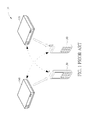
- FIG.1 is a schematic diagram of a wireless power system 10.
- the wireless power system includes two wireless power base stations 120 and 140 and two mobile devices 100 and 130.
- the wireless power base station 120 is supplying power to the mobile device 100 while the wireless power base station 140 is supplying power to the mobile device 130 (denoted with a blank arrow).
- the mobile device 100 mistakenly connects to the wireless power base station 140instead of the wireless power base station 120 (denoted with a dashed arrow).
- the mobile device 130 which shall connect to the wireless power base station 140 now connects to the wireless power base station 120.
- the mobile device 100 connects to (and thus communicates with) the wireless power base station 140 which is not the wireless power base station 120 supplying power to this mobile device 100.
- the wireless power base stations 120 and 140 cannot identify the mobile devices 100 and 130 to which they are supplying power to get correct feedback information from the mobile devices 100 and 130. Due to the mismatch, the information sent from either the wireless power base station or the mobile device may go to wrong destination.For example, the wireless power base stations 120 and 140may provide wrong, e.g. excess or deficient, charging power to the mobile devices 100 and 130.
- An objective of the present invention is to provide a method of identifying wireless power receiver in wireless power system.
- the present invention discloses a method of identifying a wireless power receiver for a mobile device in a wireless power system includes transmitting a first identity of the mobile device to a wireless power base station of the wireless power system via a first wireless communication interface, receiving a first message including the first identity from the wireless power base station via a second wireless communication interface, and identifying the first message is destined for the mobile device according to the first identity included in the first message.
- the present invention further discloses a method of identifying wireless power receiver for a wireless power base station in a wireless power system includes receiving a first identity from a mobile device of the wireless power system via a first wireless communication interface, and transmitting a first message including the first identity to the mobile device via a second wireless communication interface, such that the mobile device is able to identify that the first message is destined for the mobile device according to the first identity included in the first message.
- FIG. 2 illustrates a schematic diagram of a wireless power system 20 according to an embodiment of the present invention.
- a wireless power system may include a plurality of mobile devices and at least one wireless power base stationwhichis able toprovide wireless power to one or more of the mobile devices.
- the wireless power system 20 is briefly composed of a wireless power base station 220 and two mobile devices200 and 230.
- the wireless power base station 220 may include a wireless power transmitter or a wireless power transmitting module with digital/analog chip(s), to supply wireless power to the mobile devices 200 and 230.
- the wireless power base station 220 only supplies wireless power to the mobile device 200 (denoted with a blank arrow).
- the mobile devices200 and 230 may be any portable mobile device such as a mobile device (MD), a mobile phone, a laptop, a tablet computer, an electronic book, a portable computer system, or at least one wireless power receiver or wireless power receiving module.
- the mobile devices200and 230 may be any mobile device using battery as its power supply, such as a wearable computing device, a wearable medical device, a portable MP3 player, etc.
- the mobile device200 may directly attach to the wireless power base station 220 or keep within a distance from the wireless power base station 220 for wireless charging.
- the mobile device 200 may receive wireless power from the wireless power base station 220 by electromagnetic induction so that the battery of the mobile device200 is charged without using any wire connection.
- the mobile device 200 may utilize a first communication technology as a first communication interface to help the power transmitter of the wireless power base station 220 to identify the targeted wireless power receiver of the mobile device 200 through a second communication interface.
- the wireless power receiver of the mobile device 200 may report its identity to the wireless power transmitter of the wireless power base station 220 via the first communication interface (denoted with a slashed arrow) in advance, and then the wireless power transmitter of the wireless power base station 220 mayuse the identity to identify the desired wireless power receiver via the second communication interface (denoted with a dashed line).
- the wireless power base station 220 may transit a first message including the identity and a command to the mobile devices 200 and 230 to instruct actions that the mobile device having the identity should execute. Then, the mobile device 200 may receive the first message including the identity and the command from the wireless power base station 220 via the second communication interface after the identity of itself is identified. The mobile device 230 may understand that the first message from the wireless power base station 220 via the second communication interface is not destined for it according to the identity, and react accordingly, e.g. stop receiving wireless power or not start to receive wireless power.
- the mobile devices 200 may transmit a second message including the identity and feedback information in response to the first message to the wireless power base station 220 via the second communication interface, such that the wireless power base station 220 may obtain the feedback information from the mobile device 200 via the second communication interface after the identity of the mobile device 200 is identified from the second message.
- the power transmitter of the wireless power base station 220 and the wireless power receiver of the mobile device 200 may use the identity to communicate with each other via the second communication interface, which ensures that the wireless power base station 220 is correctly connected to the mobile device 200, so as to prevent the mismatchissue.
- FIG. 3 is a functional block diagram of the wireless power system 20 shown in FIG. 2 according to an embodiment of the present invention. Since the mobile devices 200 and 230 may be functionally identical, there are the mobile device 200 and the wireless power base station 220 shown in FIG. 3 for simplicity.
- the mobile device 200 includes a battery unit 201 and a wireless power receiver 206.
- the wireless power receiver 206 may include a power pick-up unit 202 used for receiving wireless power to charge the battery unit 201 and a communication and control unit 203 used for communicating, i.e. sending/receiving signals or packets, with the wireless power base station 220 via the power signals and controlling the operation of the power pick-up unit 202.
- the communication and control unit 203 may include first and second communication interfacing units204and 205.
- the first communication interfacing unit 204 is used for transmitting an identity or messages associated with the identity to the wireless power base station 220 by using In-Band communication channel, in which communication channels are attached on wireless power signal.
- the first communication interface may be uni-directional.
- the communication from the mobile device 200 to the wireless power base station 220 may be carried out by using Load modulation (LM) on wireless power signal.
- LM Load modulation
- FSK frequency-shift keying
- the second communication interfacing unit 205 is used for communicating by using Out-of-Band communication channel.
- the second communication interface may be bi-directional.
- the communication between the mobile device 200 and the wireless power base station 220 may be implemented by radio transceivers that transmit and receive radio signals (e.g., messages, emails, or packets) in an Out-of-Band communication channel (e.g. a short-range communication protocol such as Bluetooth, Bluetooth Low Energy (BLE), Wi-Fi, Zigbee, Near Field Communication (NFC), Device-to-Device (D2D) or Machine-to-Machine (M2M) communication defined by 3rd generation partnership project (3GPP)).
- radio signals e.g., messages, emails, or packets
- an Out-of-Band communication channel e.g. a short-range communication protocol such as Bluetooth, Bluetooth Low Energy (BLE), Wi-Fi, Zigbee, Near Field Communication (NFC), Device-to-Device (D2D) or Machine-to-Machine (M2M) communication defined by 3rd generation partnership project (3GPP)
- BLE Bluetooth
- the wireless power base station 220 includes a wireless power transmitter 226 and a system unit 222.
- the wireless power transmitter 226 may include a power conversion unit 221 used for supplying wireless power and a communication and a control unit 223 used for communicating, i.e., sending/receiving signals or packets, with the mobile device 200 and controlling the operation of the power conversion unit 221.
- the communication and control unit 223 may include first and second communication interfacing units 224 and 225.
- the first communication interfacing unit 224 is used for communicating with the first communication interfacing unit 204 of the mobile device 200 by using In-Band communication channel.
- the second communication interfacing unit 225 is used for communicating with the second communication interfacing unit 205 by using Out-of-Band communication channel.
- the first and/or second communication interfacing units 204, 205, 224 and 225 may include definitions of bits, bytes and packets with header and payload, as long as the communication interfacing units have the same understanding to realize messages sent from each other.
- the system unit 222 may include a processing means such as a microcontroller, microprocessor or an Application Specific Integrated Circuit (ASIC), for handling wireless charging authentication function activated by a processing result of the wireless power transmitter 226.
- a processing means such as a microcontroller, microprocessor or an Application Specific Integrated Circuit (ASIC)
- ASIC Application Specific Integrated Circuit
- the wireless power base station 220 contains one wireless power transmitter 226.
- the wireless power base station may contain multiple wireless power transmitters for supplying wireless power to multiple portable mobile devices.
- the wireless power base station 220 including the wireless power transmitter 226 and the mobile device 200 including the wireless power receiver 206
- the first communication interface is In-Band and is based on Load Modulation of wireless power signal from the wireless power transmitter 226 to the wireless power receiver 206
- the first communication interface is auni-directional interface from mobile device 200 to wireless power base station 220.
- the second communication interface is Out-band and is based on Bluetooth Low Energy (BLE).
- BLE Bluetooth Low Energy
- the unique identity includes Manufacture Code and Basic Device Identifier, wherein the Manufacture Code is used to identify the manufacturer of the wireless power receiver 206 while the Basic Device Identifier is used to identify the wireless power receiver 206 produced by this manufacturer.
- the mobile device 200 When the mobile device 200 comes closed to the wireless power base station 220 and finds the wireless power signal, the mobile device 200transmits a firstidentityof itself to the wireless power base station 220 via the communication interface based on Load Modulation. After the wireless power base station 220 receives the first identity and when the wireless power base station 220 wants to know the desired charging voltage of the mobile device 200, the wireless power base station 220 transmits a request to the mobile device 200 via the BLE, in which the first identity of the mobile device 200 is included. Then,each of the mobile devices 200 and 230 receiving the request mayunderstand whether it is the targeted mobile device by comparing the first identity included in the request with the identity of itsown.
- the mobile device 200 may further transmit a second message including its desired charging voltage to the wireless power base station 220 through BLE.
- the first identity of the mobile device 200 is also included such that the wireless power base station 220 can understand whether the desired charging voltage in the received second message is from the targeted mobile device 200.
- the wireless power base station 220 and the mobile device 200 may use the first identity to communicate with each other via BLE, which ensures that the wireless power base station 220 is correctly connected to the mobile device 200, so as to prevent the mismatchissue.
- FIG. 4 is a flowchart of a process 40 according to an embodiment of the present invention.
- the process 40 may be utilized for a mobile device, such as the mobile device200 or 230 shown in FIG. 2 , to realize identifying wireless power receiver in the wireless power system 20.
- the process 40 includes the following steps:
- the mobile device 200 is configured to transmit a first identityto the wireless power base station 220 via a first communication interface.
- the mobile device 200 receives a first message associated with the first identity from the wireless power base station via a second communication interface, and identify that the first message is destined for itself according to the first identity included in the first message.
- the mobile device 200 utilizes the first communication interface to transmit the first identity to the wireless power base station 220, such that the mobile device 200 and the wireless power base station may communicate with each other by identifying the first identity.
- the mobile device 230 may understand that the first message is not destined for the mobile device 230, and the mobile device 230 may ignore the first message, stop receiving wireless power, or not start to receive wireless power.
- the process 40 may ensure that the wireless power base station 220 is correctly connected to the mobile device 200 by identifying the first identity of the mobile device 200, so as to prevent the mismatchissue.
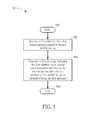
- FIG. 5 is a flowchart of a process 50 according to an embodiment of the present invention.
- the process 50 may be utilized for the wireless power base station, such as the wireless power base station 220 shown in FIG. 2 , to realize identifying a wireless power receiver in the wireless power system 20.
- the process 50 includes the following steps:
- the wireless power base station 220 is configured to receive a first identity from the mobile device 200 via a first communication interface.
- the wireless power base station 220 then transmits a first message including the first identity to the mobile device 200 via a second communication interface.
- the wireless power base station 220 utilizes the first communication interface to receive the first identity of the mobile device 200, such that the mobile device 200 and the wireless power base station 220 may communicate with each other by identifying the first identity.
- the process 50 may ensure that the wireless power base station 220 is correctly connected to the mobile device 200 by identifying the first identity of the mobile device 200, so as to prevent the mismatchissue.
- the first message transmitted from the wireless power base station 220 may be commands or information (i.e. the first message) for instructing actions that the mobile device 200 should execute, such as stop receiving the wireless power.
- the commands or information may be authentication information that the mobile device 200 provided, such as password or personal ID.
- the commands or information may be parameters of the mobile device 200 or the wireless power receiver in the mobile device 200, such as desired voltage.
- the commands or information may be data that applications on the mobile device 200 want to send to the wireless power base station 220, such as a menu request or a location request.
- the mobile device 200 may further transmit a second message including the first identity to the wireless power base station 220 in response to the first message.
- the mobile device 200 may transmit the second message to provide feedback or information in response to the first message.
- the feedback or information may be an amount of power that the mobile device received.
- the feedback or information may be authentication information that the mobile device provided, such as password or personal ID.
- the feedback or information may be parameters of the mobile device or the wireless power receiver206 in the mobile device 200, such as desired voltage.
- the feedback or information may be data that applications on the mobile device 200 want to send to the wireless power base station 220, such as a menu request or a location request.
- the mobile device 200 may receive a third message associated with a second identity, find out that the third message is not destined for the mobile device 200,andreact accordingly, e.g. ignore the third message.
- the first identity may be series of number, which may be denoted as a series of bits.
- the first identity may be a unique device identification (ID) of the wireless power receiver in the mobile device 200, which is determined by a manufacturer of the wireless power receiver in the mobile device 200,e.g. the device ID may be defined in section 6.3.8 and section 6.3.9 in WPC Low Power specification v1.1.2, which includes Manufacture Code and (Basic/Extended) Device Identifier.
- the first identity may be originated from other modules in the mobile device 200.
- One example is to use an International Mobile Subscriber Identity (IMSI) or a Radio Network Temporary Identifier (RNTI) from cellular modules.
- IMSI International Mobile Subscriber Identity
- RNTI Radio Network Temporary Identifier
- the identityprovided from other modules may be encoded (e.g. scrambled, truncated) to become the first identity of the mobile device 200.
- the first identity may be dynamically configured.
- the first message transmitted from the wireless power base station 220 may include both the first identity and a first series of data bits. Bits in the first identity may be placed in front of the first series of data bits. In one example, the first series of data bits may be placed in front of the bits in the first identity. Or, the bits in the first identity and the first series of data bits may be mixed.
- the second message transmitted from the mobile device 200 to the wireless power base station 220 may include both the first identity and a second series of data bits. Bits in the first identity may be placed in front of the second series of data bits. In one example, the second series of data bits may be placed in front of the bits in the first identity. Or, the bits in the first identity and the second series of data bits may be mixed.
- All mobile devices may find the first identity of the mobile device 200 from the first message by truncating, decoding or descrambling. In one example, all mobile devices (including the mobile device 200) may compare the first identity included in the first message with its identity, and understand the first series of data bits included in the first message is destined for the mobile device 200. The mobile device 230 other than the mobile device 200 received the first message may understand the first series of data bits is not destined for itself, afterdecoding error or other types of errors for the first message occur.
- FIG. 6 illustrates a bi-phase encoding scheme of modulation of wireless power signals.
- f CLK 2 KHz
- T CLK One bit is denoted by two transitions and thus the data rate is just one Kbps. Therefore, the wireless power receiver and the power transmitter may detect the transitions of the wireless power signals to decode the identity of the mobile device.
- the abovementioned steps of the processes 40 and 50 including suggested steps may be realized by means of hardware, software, firmware, or an electronic system.
- Examples of hardware may include analog, digital and mixed circuits known as microcircuit, microchip, or silicon chip.
- Examples of the electronic system may include a system on chip (SOC), system in package (SiP), and a computer on module (COM).
- SOC system on chip
- SiP system in package
- COM computer on module
- the present invention provides a methodof identifying a wireless power receiver in a wireless power system.
- the wireless power base station and the mobile device may use the first identity to communicate with each other via the second communication interface, which ensures that the wireless power base station is correctly connected to the mobile device having the first identity, so as to prevent the mismatchissue.
Landscapes
- Engineering & Computer Science (AREA)
- Computer Networks & Wireless Communication (AREA)
- Signal Processing (AREA)
- Mobile Radio Communication Systems (AREA)
Abstract
Description
- The present invention relates to a method used in a wireless power system, and more particularly, to a method of identifying a wireless power receiver in a wireless power system.
- With the proliferation of portable electronic devices such as mobile device (MD), smart phone and tablet PC, the demand for charging devices, especially for those provided in public areas, is increasing. In addition, people would like to get rid of annoying wires if possible. One technology which realizes this desire is wireless charging, in which portable electronic device(s) comprising a wire less power receiver is placed on and charged through a wireless power base station (e.g. a power base station comprising a wireless power transmitter).
- Wireless Power Consortium (WPC) is a leading organization in the world in defining wireless charging specification. The document 'Wireless Power Transfer - Volume I, part I' in version 1.1.2 released in June 2013 describes an inter-operability interface between a wireless power transmitter (PTX) and a wireless power receiver (PRX).
- Currently, the WPC is starting to define a new wireless power standard based on resonant technology, which is also known as Out-of-Band communication technology, wherein a communication interface based on the technologies with higher data rate such as Bluetooth Low Energy (BLE) and Near Field Communication (NFC) is discussed. Among the two candidates, the BLE can reach one Mbps data rate and the NFC can have four hundred Kbps data rate, which implies more applications become possible if such Out-of-Band communication technologies are adopted.
- Communication interface is critical due to the need to exchange information between the wireless power transmitter and the wireless power receiver.However,since the Out-of-Band communication technology is not based on modulation of wireless power signals, a mismatch issue, or cross connection, shall be considered. Actually, such mismatch issueis already existed in another standard defined by Alliance for wireless power (A4WP), in which the communication interface between the wireless power transmitter and the wireless power receiver is based on the BLE.
- Specifically, please refer to
FIG.1 , which is a schematic diagram of awireless power system 10. The wireless power system includes two wirelesspower base stations mobile devices 100 and 130.The wirelesspower base station 120 is supplying power to themobile device 100 while the wirelesspower base station 140 is supplying power to the mobile device 130 (denoted with a blank arrow). There shall be a communication interface between the wirelesspower base station 120 and themobile device 100, which allows the wirelesspower base station 120 to get feedback information, such as the amount of power received, from themobile device 100. However, in some cases themobile device 100 mistakenly connects to the wireless power base station 140instead of the wireless power base station 120 (denoted with a dashed arrow). On the other hand, themobile device 130 which shall connect to the wirelesspower base station 140 now connects to the wirelesspower base station 120. In other words,themobile device 100 connects to (and thus communicates with) the wirelesspower base station 140 which is not the wirelesspower base station 120 supplying power to this mobile device 100.It is indeed a mismatch and both the wirelesspower base stations mobile devices mobile devices power base stations 120 and 140may provide wrong, e.g. excess or deficient, charging power to themobile devices - Therefore, there is a need to implement identification mechanism between the mobile device and the wireless power base station to solve the abovementioned issue.
- An objective of the present invention is to provide a method of identifying wireless power receiver in wireless power system.
- The present invention discloses a method of identifying a wireless power receiver for a mobile device in a wireless power system includes transmitting a first identity of the mobile device to a wireless power base station of the wireless power system via a first wireless communication interface, receiving a first message including the first identity from the wireless power base station via a second wireless communication interface, and identifying the first message is destined for the mobile device according to the first identity included in the first message.
- The present invention further discloses a method of identifying wireless power receiver for a wireless power base station in a wireless power system includes receiving a first identity from a mobile device of the wireless power system via a first wireless communication interface, and transmitting a first message including the first identity to the mobile device via a second wireless communication interface, such that the mobile device is able to identify that the first message is destined for the mobile device according to the first identity included in the first message.
- These and other objectives of the present invention will no doubt become obvious to those of ordinary skill in the art after reading the following detailed description of the preferred embodiment that is illustrated in the various figures and drawings.
-
-
FIG. 1 is a schematic diagram of a wireless power system. -
FIG. 2 illustrates a schematic diagram of a wireless power system according to an embodiment of the present invention. -
FIG. 3 is a functional block diagram of the wireless power system shown inFIG. 2 according to an embodiment of the present invention. -
FIG. 4 is a flowchart of a process according to an embodiment of the present invention. -
FIG. 5 is a flowchart of a process according to an embodiment of the present invention. -
FIG. 6 illustrates a bi-phase encoding scheme of modulation of wireless power signals. - Please refer to
FIG. 2 , which illustrates a schematic diagram of awireless power system 20 according to an embodiment of the present invention. A wireless power systemmay include a plurality of mobile devices and at least one wireless power base stationwhichis able toprovide wireless power to one or more of the mobile devices. For example, inFIG. 2 , thewireless power system 20 is briefly composed of a wirelesspower base station 220 and two mobile devices200 and 230. - The wireless
power base station 220 may include a wireless power transmitter or a wireless power transmitting module with digital/analog chip(s), to supply wireless power to themobile devices power base station 220 only supplies wireless power to the mobile device 200 (denoted with a blank arrow). The mobile devices200 and 230 may be any portable mobile device such as a mobile device (MD), a mobile phone, a laptop, a tablet computer, an electronic book, a portable computer system, or at least one wireless power receiver or wireless power receiving module. Alternatively, themobile devices200and 230 may be any mobile device using battery as its power supply, such as a wearable computing device, a wearable medical device, a portable MP3 player, etc. The mobile device200 may directly attach to the wirelesspower base station 220 or keep within a distance from the wirelesspower base station 220 for wireless charging. The mobile device 200may receive wireless power from the wirelesspower base station 220 by electromagnetic induction so that the battery of the mobile device200 is charged without using any wire connection. - In order to conquer the mismatchissue, i.e. ensure that the wireless
power base station 220 is correctly connected to themobile device 200, themobile device 200 may utilize a first communication technology as a first communication interface to help the power transmitter of the wirelesspower base station 220 to identify the targeted wireless power receiver of themobile device 200 through a second communication interface. - Specifically, as shown in
FIG. 2 , the wireless power receiver of themobile device 200 may report its identity to the wireless power transmitter of the wirelesspower base station 220 via the first communication interface (denoted with a slashed arrow) in advance, and then the wireless power transmitter of the wirelesspower base station 220 mayuse the identity to identify the desired wireless power receiver via the second communication interface (denoted with a dashed line). - For example, the wireless
power base station 220 may transit a first message including the identity and a command to themobile devices mobile device 200 may receive the first message including the identity and the command from the wirelesspower base station 220 via the second communication interface after the identity of itself is identified. Themobile device 230 may understand that the first message from the wirelesspower base station 220 via the second communication interface is not destined for it according to the identity, and react accordingly, e.g. stop receiving wireless power or not start to receive wireless power. - In one example, the
mobile devices 200 may transmit a second message including the identity and feedback information in response to the first message to the wirelesspower base station 220 via the second communication interface, such that the wirelesspower base station 220 may obtain the feedback information from themobile device 200 via the second communication interface after the identity of themobile device 200 is identified from the second message. - Therefore, the power transmitter of the wireless
power base station 220 and the wireless power receiver of themobile device 200 may use the identity to communicate with each other via the second communication interface, which ensures that the wirelesspower base station 220 is correctly connected to themobile device 200, so as to prevent the mismatchissue. - Please refer to
FIG. 3 , which is a functional block diagram of thewireless power system 20 shown inFIG. 2 according to an embodiment of the present invention. Since themobile devices mobile device 200 and the wirelesspower base station 220 shown inFIG. 3 for simplicity. Themobile device 200 includes abattery unit 201 and awireless power receiver 206. Thewireless power receiver 206 may include a power pick-up unit 202 used for receiving wireless power to charge thebattery unit 201 and a communication andcontrol unit 203 used for communicating, i.e. sending/receiving signals or packets, with the wirelesspower base station 220 via the power signals and controlling the operation of the power pick-up unit 202. - The communication and
control unit 203 may include first and secondcommunication interfacing units204and 205. The firstcommunication interfacing unit 204 is used for transmitting an identity or messages associated with the identity to the wirelesspower base station 220 by using In-Band communication channel, in which communication channels are attached on wireless power signal. Preferably,the first communication interface may be uni-directional. The communication from themobile device 200 to the wirelesspower base station 220 may be carried out by using Load modulation (LM) on wireless power signal. Alternatively, the communication from the wirelesspower base station 220 to themobile device 200 may be carried out by using frequency-shift keying (FSK) modulation on the wireless power signal. The secondcommunication interfacing unit 205 is used for communicating by using Out-of-Band communication channel. Preferably, the second communication interface may be bi-directional. The communication between themobile device 200 and the wirelesspower base station 220 may be implemented by radio transceivers that transmit and receive radio signals (e.g., messages, emails, or packets) in an Out-of-Band communication channel (e.g. a short-range communication protocol such as Bluetooth, Bluetooth Low Energy (BLE), Wi-Fi, Zigbee, Near Field Communication (NFC), Device-to-Device (D2D) or Machine-to-Machine (M2M) communication defined by 3rd generation partnership project (3GPP)). - The wireless
power base station 220 includes awireless power transmitter 226 and asystem unit 222. Thewireless power transmitter 226 may include apower conversion unit 221 used for supplying wireless power and a communication and acontrol unit 223 used for communicating, i.e., sending/receiving signals or packets, with themobile device 200 and controlling the operation of thepower conversion unit 221. - The communication and
control unit 223 may include first and secondcommunication interfacing units communication interfacing unit 224 is used for communicating with the firstcommunication interfacing unit 204 of themobile device 200 by using In-Band communication channel. The secondcommunication interfacing unit 225 is used for communicating with the secondcommunication interfacing unit 205 by using Out-of-Band communication channel. In addition, the first and/or secondcommunication interfacing units - The
system unit 222 may include a processing means such as a microcontroller, microprocessor or an Application Specific Integrated Circuit (ASIC), for handling wireless charging authentication function activated by a processing result of thewireless power transmitter 226. In the example ofFIG. 3 , the wirelesspower base station 220 contains onewireless power transmitter 226. In other examples, the wireless power base station may contain multiple wireless power transmitters for supplying wireless power to multiple portable mobile devices. - In practice, considering the wireless
power base station 220 including thewireless power transmitter 226 and themobile device 200 including thewireless power receiver 206, and there exist two communication interfaces between the wirelesspower base station 220 andmobile device 200. The first communication interface is In-Band and is based on Load Modulation of wireless power signal from thewireless power transmitter 226 to thewireless power receiver 206, and the first communication interface is auni-directional interface frommobile device 200 to wirelesspower base station 220. The second communication interface is Out-band and is based on Bluetooth Low Energy (BLE). In this embodiment, it is assumedthat there are BLE modules (i.e. the secondcommunication interfacing units 205 and 225) in both the wirelesspower base station 220 and themobile device 200, and everymobile device wireless power receiver 206 while the Basic Device Identifier is used to identify thewireless power receiver 206 produced by this manufacturer. - When the
mobile device 200 comes closed to the wirelesspower base station 220 and finds the wireless power signal, the mobile device 200transmits a firstidentityof itself to the wirelesspower base station 220 via the communication interface based on Load Modulation. After the wirelesspower base station 220 receives the first identity and when the wirelesspower base station 220 wants to know the desired charging voltage of themobile device 200, the wirelesspower base station 220 transmits a request to themobile device 200 via the BLE, in which the first identity of themobile device 200 is included. Then,each of themobile devices - For the
mobile device 200 which finds that the first identity in the received request is the same as the identity of its own, themobile device 200 may further transmit a second message including its desired charging voltage to the wirelesspower base station 220 through BLE. In the second message, the first identity of themobile device 200 is also included such that the wirelesspower base station 220 can understand whether the desired charging voltage in the received second message is from the targetedmobile device 200. - Therefore, by transmitting the first identity via the Load Modulation to the
wireless power transmitter 226 of the wirelesspower base station 220 in advance, the wirelesspower base station 220 and themobile device 200 may use the first identity to communicate with each other via BLE, which ensures that the wirelesspower base station 220 is correctly connected to themobile device 200, so as to prevent the mismatchissue. - Please refer to
FIG. 4 , which is a flowchart of aprocess 40 according to an embodiment of the present invention. Theprocess 40 may be utilized for a mobile device, such as the mobile device200 or 230 shown inFIG. 2 , to realize identifying wireless power receiver in thewireless power system 20. Theprocess 40 includes the following steps: - Step 400: Start.
- Step 402:Transmit a first identity to a wireless power base station via a first communication interface.
- Step 404:Receive a first message including the firstidentity from the wireless power base station via a second communication interface.
- Step 406: Identify that the first message is destined to the mobile device according to the first identity included in the first message.
- Step 408: End.
- According to the
process 40, themobile device 200 is configured to transmit a first identityto the wirelesspower base station 220 via a first communication interface. Themobile device 200 then receives a first message associated with the first identity from the wireless power base station via a second communication interface, and identify that the first message is destined for itself according to the first identity included in the first message. In other words, themobile device 200 utilizes the first communication interface to transmit the first identity to the wirelesspower base station 220, such that themobile device 200 and the wireless power base station may communicate with each other by identifying the first identity. On the other hand, if themobile device 230 realizes that the first identity of the first message transmitted from the wirelesspower base station 220 via the second communication interface is not identified, themobile device 230 may understand that the first message is not destined for themobile device 230, and themobile device 230 may ignore the first message, stop receiving wireless power, or not start to receive wireless power. - As a result, the
process 40 may ensure that the wirelesspower base station 220 is correctly connected to themobile device 200 by identifying the first identity of themobile device 200, so as to prevent the mismatchissue. - Please refer to
FIG. 5 , which is a flowchart of aprocess 50 according to an embodiment of the present invention. Theprocess 50 may be utilized for the wireless power base station, such as the wirelesspower base station 220 shown inFIG. 2 , to realize identifying a wireless power receiver in thewireless power system 20. Theprocess 50 includes the following steps: - Step 500: Start.
- Step 502: Receive a first identity via a first communication interface from a mobile device.
- Step 504: Transmit a first message including the first identity via a second communication interface to the mobile device after the first identity of the mobile device is identified from the first message.
- Step 506: End.
- According to the
process 50, the wirelesspower base station 220 is configured to receive a first identity from themobile device 200 via a first communication interface. The wirelesspower base station 220 then transmits a first message including the first identity to themobile device 200 via a second communication interface. In other words, the wirelesspower base station 220 utilizes the first communication interface to receive the first identity of themobile device 200, such that themobile device 200 and the wirelesspower base station 220 may communicate with each other by identifying the first identity. As a result, theprocess 50 may ensure that the wirelesspower base station 220 is correctly connected to themobile device 200 by identifying the first identity of themobile device 200, so as to prevent the mismatchissue. - Note that the
processes power base station 220 may be commands or information (i.e. the first message) for instructing actions that themobile device 200 should execute, such as stop receiving the wireless power. In one example, the commands or information may be authentication information that themobile device 200 provided, such as password or personal ID. In one example, the commands or information may be parameters of themobile device 200 or the wireless power receiver in themobile device 200, such as desired voltage. In one example, the commands or information may be data that applications on themobile device 200 want to send to the wirelesspower base station 220, such as a menu request or a location request. - Moreover, the
mobile device 200 may further transmit a second message including the first identity to the wirelesspower base station 220 in response to the first message. For example, themobile device 200 may transmit the second message to provide feedback or information in response to the first message. For example, the feedback or information may be an amount of power that the mobile device received. In one example, the feedback or information may be authentication information that the mobile device provided, such as password or personal ID. In one example, the feedback or information may be parameters of the mobile device or the wireless power receiver206 in themobile device 200, such as desired voltage. In one example, the feedback or information may be data that applications on themobile device 200 want to send to the wirelesspower base station 220, such as a menu request or a location request. In one example, themobile device 200 may receive a third message associated with a second identity, find out that the third message is not destined for themobile device 200,andreact accordingly, e.g. ignore the third message. - The first identity may be series of number, which may be denoted as a series of bits. In one example, the first identity may be a unique device identification (ID) of the wireless power receiver in the
mobile device 200, which is determined by a manufacturer of the wireless power receiver in themobile device 200,e.g. the device ID may be defined in section 6.3.8 and section 6.3.9 in WPC Low Power specification v1.1.2, which includes Manufacture Code and (Basic/Extended) Device Identifier. In one example, the first identity may be originated from other modules in themobile device 200. One example is to use an International Mobile Subscriber Identity (IMSI) or a Radio Network Temporary Identifier (RNTI) from cellular modules. Another example is to use the NFC or BLE ID from NFC or Bluetooth modules. The identityprovided from other modules may be encoded (e.g. scrambled, truncated) to become the first identity of themobile device 200. In one example, the first identity may be dynamically configured. - The first message transmitted from the wireless
power base station 220 may include both the first identity and a first series of data bits. Bits in the first identity may be placed in front of the first series of data bits. In one example, the first series of data bits may be placed in front of the bits in the first identity. Or, the bits in the first identity and the first series of data bits may be mixed. - The second message transmitted from the
mobile device 200 to the wirelesspower base station 220 may include both the first identity and a second series of data bits. Bits in the first identity may be placed in front of the second series of data bits. In one example, the second series of data bits may be placed in front of the bits in the first identity. Or, the bits in the first identity and the second series of data bits may be mixed. - All mobile devices (including the mobile device 200) may find the first identity of the
mobile device 200 from the first message by truncating, decoding or descrambling. In one example, all mobile devices (including the mobile device 200) may compare the first identity included in the first message with its identity, and understand the first series of data bits included in the first message is destined for themobile device 200. Themobile device 230 other than themobile device 200 received the first message may understand the first series of data bits is not destined for itself, afterdecoding error or other types of errors for the first message occur. - Specifically, please refer to
FIG. 6 , which illustrates a bi-phase encoding scheme of modulation of wireless power signals. As shown inFIG. 6 , wireless power signals is differentially encoded with a clock rate of fCLK=2 KHz, wherein a period is TCLK. One bit is denoted by two transitions and thus the data rate is just one Kbps. Therefore, the wireless power receiver and the power transmitter may detect the transitions of the wireless power signals to decode the identity of the mobile device. - The abovementioned steps of the
processes - To sum up, the present invention provides a methodof identifying a wireless power receiver in a wireless power system. By transmitting the first identity of the mobile device via the first communication interface to the wireless power transmitter of the wireless power base station in advance, the wireless power base station and the mobile device may use the first identity to communicate with each other via the second communication interface, which ensures that the wireless power base station is correctly connected to the mobile device having the first identity, so as to prevent the mismatchissue.
- Those skilled in the art will readily observe that numerous modifications and alterations of the device and method may be made while retaining the teachings of the invention. Accordingly, the above disclosure should be construed as limited only by the metes and bounds of the appended claims.
Claims (15)
- A method of identifying a wireless power receiver (206) for a mobile device (200)in a wireless power system (20), comprising:transmitting a first identityof the mobile device (200) to a wireless power base station (220) of the wireless power system (20) via a first wireless communication interface;receiving a first message including the first identityfrom the wireless power base station (220) via a second wireless communication interface; andidentifying the first message is destined for the mobile device(200) according to the first identity included in the first message.
- The method of claim 1, further comprising:transmitting a second message including the first identity to the wireless power base station (220)in response to the first message via the second wireless communication interface.
- The method of claim 1, further comprising:receiving a third message including a second identity from the wireless power base station (220) via the second wireless communication interface; andidentifying the third message is not destined for the mobile device (200) according to the second identity included in the third message.
- The method of claim 1, wherein the first wireless communication interface is a uni-directional wireless communication interface.
- The method of claim 1, wherein the first wireless communication interface is In-Band, which is realized by a modulation of wireless power signals of the wireless power base station (220), and the modulation is Frequency-Shift Keying modulation or Load modulation.
- The method of claim 1, wherein the second wireless communication interface is a bi-directional wireless communication interface.
- The method of claim 1, wherein the second wireless communication interface is Out-of-Band, which is realized by Bluetooth Low Energy, Near Field Communication, Zigbee, Wifi-Direct communication, Device-to-Device communication or Machine-to-Machine communication defined by third generation partnership project.
- The method of claim 1, wherein the first identity is an identity of the wireless power receiver (206) of the mobile device (200).
- A method of identifying a wireless power receiver (206) for a wireless power base station (220) in a wireless power system (20), comprising:receiving a first identity from a mobile device (200) of the wireless power system (20) via a first wireless communication interface; andtransmitting a first message including the first identity to the mobile device (200) via a second wireless communication interface, such that the mobile device (200) is able to identify that the first message is destined for the mobile device (200) according to the first identity included in the first message.
- The method of claim 9, further comprising:receiving a second message including the first identity from the mobile device (200) in response to the first message via the second wireless communication interface.
- The method of claim 9, wherein the first wireless communication interface is a uni-directional wireless communication interface.
- The method of claim 9, wherein the first wireless communication interface is In-Band, which is realized by a modulation of wireless power signals of the wireless power base station (220), and the modulation is Frequency-Shift Keying modulation or Load modulation.
- The method of claim 9, wherein the second wireless communication interface is a bi-directional wireless communication interface.
- The method of claim 9, wherein the second wireless communication interface is Out-of-Band, which is realized by Bluetooth Low Energy, Near Field Communication, Zigbee, Wifi-Direct communication, Device-to-Device communication or Machine-to-Machine communication defined by third generation partnership project.
- The method of claim 9, wherein the first identity is an identity of the wireless power receiver (206) of the mobile device (200).
Applications Claiming Priority (1)
| Application Number | Priority Date | Filing Date | Title |
|---|---|---|---|
| US201361895415P | 2013-10-25 | 2013-10-25 |
Publications (1)
| Publication Number | Publication Date |
|---|---|
| EP2866357A1 true EP2866357A1 (en) | 2015-04-29 |
Family
ID=51794781
Family Applications (1)
| Application Number | Title | Priority Date | Filing Date |
|---|---|---|---|
| EP20140190267 Withdrawn EP2866357A1 (en) | 2013-10-25 | 2014-10-24 | Method of identifying a wireless power receiver in a wireless power system |
Country Status (2)
| Country | Link |
|---|---|
| US (1) | US9548795B2 (en) |
| EP (1) | EP2866357A1 (en) |
Families Citing this family (10)
| Publication number | Priority date | Publication date | Assignee | Title |
|---|---|---|---|---|
| CN104603849B (en) * | 2015-02-12 | 2017-03-15 | 深圳来电科技有限公司 | Portable power source automatic lending equipment |
| JP6550914B2 (en) * | 2015-05-13 | 2019-07-31 | セイコーエプソン株式会社 | Control device, electronic device and non-contact power transmission system |
| US20160366144A1 (en) * | 2015-06-10 | 2016-12-15 | Huawei Technologies Co., Ltd. | System Security Using Multi-user Control |
| US10461586B2 (en) * | 2016-03-31 | 2019-10-29 | Intel Corporation | Methods and apparatus for cross connection detection and mitigation in wireless power transfer networks |
| KR20190054416A (en) * | 2017-11-13 | 2019-05-22 | 삼성전기주식회사 | Wireless power transmission apparatus |
| JP7117884B2 (en) | 2018-04-09 | 2022-08-15 | キヤノン株式会社 | Power Receiving Device, Power Transmitting Device, Control Method, and Program |
| CN110380517B (en) * | 2018-04-11 | 2022-10-21 | 台达电子工业股份有限公司 | Wireless power transmission system and transmission method |
| KR102564363B1 (en) * | 2018-07-27 | 2023-08-08 | 삼성전자 주식회사 | Electronic device for controlling a communication channel associated with wireless charging based on identification information received from external device and methd for the same |
| WO2020149492A1 (en) * | 2019-01-17 | 2020-07-23 | 엘지전자 주식회사 | Device and method for wireless power transfer to multiple devices using multi-coil |
| EP4142109A4 (en) * | 2020-04-21 | 2024-05-29 | LG Electronics, Inc. | Wireless power receiver and wireless power transmitter |
Citations (3)
| Publication number | Priority date | Publication date | Assignee | Title |
|---|---|---|---|---|
| WO2009123079A1 (en) * | 2008-04-01 | 2009-10-08 | Canon Kabushiki Kaisha | Digital camera connected to a computer using rfid authenti fi cati on |
| EP2592762A1 (en) * | 2011-11-10 | 2013-05-15 | LG Innotek Co., Ltd. | Wireless power transmitter, wireless power receiver, wireless power transmission method and wireless power reception method |
| US20130257364A1 (en) * | 2012-04-03 | 2013-10-03 | Qualcomm Incorporated | System and method for wireless power control communication using bluetooth low energy |
Family Cites Families (5)
| Publication number | Priority date | Publication date | Assignee | Title |
|---|---|---|---|---|
| US6987764B2 (en) * | 2001-11-05 | 2006-01-17 | Qualcomm, Incorporated | Method and apparatus for selecting a packet data serving node for multi-cast/broadcast services |
| US9312728B2 (en) * | 2009-08-24 | 2016-04-12 | Access Business Group International Llc | Physical and virtual identification in a wireless power network |
| US8850492B2 (en) * | 2011-07-15 | 2014-09-30 | Blackberry Limited | Method, system and apparatus for delivering data to a mobile electronic device |
| US9386479B2 (en) * | 2012-05-22 | 2016-07-05 | Qualcomm Incorporated | Method and apparatus of implementing a body area network using a mesh configuration |
| US9973038B2 (en) * | 2013-06-10 | 2018-05-15 | Celico Partnership | Self optimizing antenna for NFC and wireless charging |
-
2014
- 2014-10-24 EP EP20140190267 patent/EP2866357A1/en not_active Withdrawn
- 2014-10-24 US US14/522,602 patent/US9548795B2/en active Active
Patent Citations (3)
| Publication number | Priority date | Publication date | Assignee | Title |
|---|---|---|---|---|
| WO2009123079A1 (en) * | 2008-04-01 | 2009-10-08 | Canon Kabushiki Kaisha | Digital camera connected to a computer using rfid authenti fi cati on |
| EP2592762A1 (en) * | 2011-11-10 | 2013-05-15 | LG Innotek Co., Ltd. | Wireless power transmitter, wireless power receiver, wireless power transmission method and wireless power reception method |
| US20130257364A1 (en) * | 2012-04-03 | 2013-10-03 | Qualcomm Incorporated | System and method for wireless power control communication using bluetooth low energy |
Non-Patent Citations (1)
| Title |
|---|
| WIRELESS POWER TRANSFER, vol. I, June 2013 (2013-06-01) |
Also Published As
| Publication number | Publication date |
|---|---|
| US20150118962A1 (en) | 2015-04-30 |
| US9548795B2 (en) | 2017-01-17 |
Similar Documents
| Publication | Publication Date | Title |
|---|---|---|
| US9548795B2 (en) | Method of identifying wireless power receiver in wireless power system | |
| US9847667B2 (en) | Method of handling wireless charging authentication | |
| EP2822142B1 (en) | Method for wireless charging authentication and related wireless charging system | |
| US10601257B2 (en) | Wireless power transmission network and wireless power transmission method | |
| US8213862B2 (en) | Headset charge via short-range RF communication | |
| US10142767B2 (en) | Method and apparatus for transmitting data using Bluetooth low energy in wireless communication system | |
| JP6275867B2 (en) | Channel reservation for operation in unlicensed spectrum | |
| CN106105310B (en) | The method and apparatus of message transmission rate is adjusted in wireless communication system | |
| KR101368166B1 (en) | Re-connection method in peripheral interface using visible light communication | |
| US20180152979A1 (en) | Method and device for connecting alternative communication means using bluetooth low energy technology | |
| US20150199665A1 (en) | Method of Payment for Wireless Charging Service | |
| US11178716B2 (en) | Method and apparatus for establishing connection between devices by using bluetooth low energy technology | |
| CN102412869B (en) | System and method for fast accessing near field communication with controllable communication range | |
| US10721611B2 (en) | Method and device for controlling device by using Bluetooth technology | |
| US20140298447A1 (en) | Method for Enhancing Security of Portable Electronic Device and Related Wireless Charging System | |
| US20150031334A1 (en) | Method of Handling Authentication for Wireless Charging | |
| US9961481B2 (en) | Method and apparatus for transmitting a HTTP data using bluetooth in wireless communication system | |
| CN105308893A (en) | Digital radio communication | |
| EP3327894A1 (en) | Wireless charging device for vehicle | |
| US10194477B2 (en) | Method and apparatus for controlling a device using bluetooth technology | |
| KR101673833B1 (en) | Double-mode and double-standby mobile terminal and communication method thereof | |
| JP6447625B2 (en) | COMMUNICATION CIRCUIT, COMMUNICATION DEVICE, COMMUNICATION METHOD, AND COMPUTER PROGRAM | |
| US20150340879A1 (en) | Power providing equipment, mobile device, operating method of mobile device | |
| CN102821086A (en) | Data transmission method and device and data receiving method and device | |
| CN112118545A (en) | Transfer equipment, server, system and login method for narrow-band and wide-band communication |
Legal Events
| Date | Code | Title | Description |
|---|---|---|---|
| PUAI | Public reference made under article 153(3) epc to a published international application that has entered the european phase |
Free format text: ORIGINAL CODE: 0009012 |
|
| 17P | Request for examination filed |
Effective date: 20141024 |
|
| AK | Designated contracting states |
Kind code of ref document: A1 Designated state(s): AL AT BE BG CH CY CZ DE DK EE ES FI FR GB GR HR HU IE IS IT LI LT LU LV MC MK MT NL NO PL PT RO RS SE SI SK SM TR |
|
| AX | Request for extension of the european patent |
Extension state: BA ME |
|
| RBV | Designated contracting states (corrected) |
Designated state(s): AL AT BE BG CH CY CZ DE DK EE ES FI FR GB GR HR HU IE IS IT LI LT LU LV MC MK MT NL NO PL PT RO RS SE SI SK SM TR |
|
| STAA | Information on the status of an ep patent application or granted ep patent |
Free format text: STATUS: THE APPLICATION IS DEEMED TO BE WITHDRAWN |
|
| 18D | Application deemed to be withdrawn |
Effective date: 20160409 |