EP2866323A1 - Auxiliary electric power system and method of regulating voltages of the same - Google Patents
Auxiliary electric power system and method of regulating voltages of the same Download PDFInfo
- Publication number
- EP2866323A1 EP2866323A1 EP20140183620 EP14183620A EP2866323A1 EP 2866323 A1 EP2866323 A1 EP 2866323A1 EP 20140183620 EP20140183620 EP 20140183620 EP 14183620 A EP14183620 A EP 14183620A EP 2866323 A1 EP2866323 A1 EP 2866323A1
- Authority
- EP
- European Patent Office
- Prior art keywords
- electric power
- auxiliary
- voltage
- motor
- generator
- Prior art date
- Legal status (The legal status is an assumption and is not a legal conclusion. Google has not performed a legal analysis and makes no representation as to the accuracy of the status listed.)
- Granted
Links
Images





Classifications
-
- H—ELECTRICITY
- H02—GENERATION; CONVERSION OR DISTRIBUTION OF ELECTRIC POWER
- H02J—ELECTRIC POWER NETWORKS; CIRCUIT ARRANGEMENTS OR SYSTEMS FOR SUPPLYING OR DISTRIBUTING ELECTRIC POWER; SYSTEMS FOR STORING ELECTRIC ENERGY
- H02J3/00—Circuit arrangements for AC mains or AC distribution networks
- H02J3/38—Arrangements for feeding a single network from two or more generators or sources in parallel; Arrangements for feeding already energised networks from additional generators or sources in parallel
- H02J3/381—Dispersed generators
-
- F—MECHANICAL ENGINEERING; LIGHTING; HEATING; WEAPONS; BLASTING
- F03—MACHINES OR ENGINES FOR LIQUIDS; WIND, SPRING, OR WEIGHT MOTORS; PRODUCING MECHANICAL POWER OR A REACTIVE PROPULSIVE THRUST, NOT OTHERWISE PROVIDED FOR
- F03D—WIND MOTORS
- F03D7/00—Controlling wind motors
- F03D7/02—Controlling wind motors the wind motors having rotation axis substantially parallel to the air flow entering the rotor
- F03D7/0272—Controlling wind motors the wind motors having rotation axis substantially parallel to the air flow entering the rotor by measures acting on the electrical generator
-
- G—PHYSICS
- G05—CONTROLLING; REGULATING
- G05B—CONTROL OR REGULATING SYSTEMS IN GENERAL; FUNCTIONAL ELEMENTS OF SUCH SYSTEMS; MONITORING OR TESTING ARRANGEMENTS FOR SUCH SYSTEMS OR ELEMENTS
- G05B15/00—Systems controlled by a computer
- G05B15/02—Systems controlled by a computer electric
-
- H—ELECTRICITY
- H02—GENERATION; CONVERSION OR DISTRIBUTION OF ELECTRIC POWER
- H02J—ELECTRIC POWER NETWORKS; CIRCUIT ARRANGEMENTS OR SYSTEMS FOR SUPPLYING OR DISTRIBUTING ELECTRIC POWER; SYSTEMS FOR STORING ELECTRIC ENERGY
- H02J11/00—Circuit arrangements for providing service supply to auxiliaries of stations in which electric power is generated, distributed or converted
-
- H—ELECTRICITY
- H02—GENERATION; CONVERSION OR DISTRIBUTION OF ELECTRIC POWER
- H02J—ELECTRIC POWER NETWORKS; CIRCUIT ARRANGEMENTS OR SYSTEMS FOR SUPPLYING OR DISTRIBUTING ELECTRIC POWER; SYSTEMS FOR STORING ELECTRIC ENERGY
- H02J2101/00—Supply or distribution of decentralised, dispersed or local electric power generation
- H02J2101/20—Dispersed power generation using renewable energy sources
- H02J2101/22—Solar energy
-
- H—ELECTRICITY
- H02—GENERATION; CONVERSION OR DISTRIBUTION OF ELECTRIC POWER
- H02J—ELECTRIC POWER NETWORKS; CIRCUIT ARRANGEMENTS OR SYSTEMS FOR SUPPLYING OR DISTRIBUTING ELECTRIC POWER; SYSTEMS FOR STORING ELECTRIC ENERGY
- H02J2101/00—Supply or distribution of decentralised, dispersed or local electric power generation
- H02J2101/20—Dispersed power generation using renewable energy sources
- H02J2101/28—Wind energy
-
- Y—GENERAL TAGGING OF NEW TECHNOLOGICAL DEVELOPMENTS; GENERAL TAGGING OF CROSS-SECTIONAL TECHNOLOGIES SPANNING OVER SEVERAL SECTIONS OF THE IPC; TECHNICAL SUBJECTS COVERED BY FORMER USPC CROSS-REFERENCE ART COLLECTIONS [XRACs] AND DIGESTS
- Y02—TECHNOLOGIES OR APPLICATIONS FOR MITIGATION OR ADAPTATION AGAINST CLIMATE CHANGE
- Y02E—REDUCTION OF GREENHOUSE GAS [GHG] EMISSIONS, RELATED TO ENERGY GENERATION, TRANSMISSION OR DISTRIBUTION
- Y02E10/00—Energy generation through renewable energy sources
- Y02E10/70—Wind energy
- Y02E10/72—Wind turbines with rotation axis in wind direction
-
- Y—GENERAL TAGGING OF NEW TECHNOLOGICAL DEVELOPMENTS; GENERAL TAGGING OF CROSS-SECTIONAL TECHNOLOGIES SPANNING OVER SEVERAL SECTIONS OF THE IPC; TECHNICAL SUBJECTS COVERED BY FORMER USPC CROSS-REFERENCE ART COLLECTIONS [XRACs] AND DIGESTS
- Y02—TECHNOLOGIES OR APPLICATIONS FOR MITIGATION OR ADAPTATION AGAINST CLIMATE CHANGE
- Y02E—REDUCTION OF GREENHOUSE GAS [GHG] EMISSIONS, RELATED TO ENERGY GENERATION, TRANSMISSION OR DISTRIBUTION
- Y02E10/00—Energy generation through renewable energy sources
- Y02E10/70—Wind energy
- Y02E10/76—Power conversion electric or electronic aspects
Definitions
- the m-g sets facilitate extending the flexibility for adapting auxiliary electric power systems and associated wind turbine generators to comply with to an extended range of ratings of grid regulations in a plurality of jurisdictions and countries, thereby facilitating extending the range of ratings of auxiliary electric power systems and associated wind turbine generators to be compatible with a plurality of grid strengths and reliabilities, including those grids with series compensated transmission lines.
- Such flexibility reduces the costs of the auxiliary equipment by facilitating use of standard auxiliary support equipment with standard voltage tolerance ratings, rather than using more expensive auxiliary support equipment that is fully complimentary to the extended voltage ranges of the associated electrical grid.
- such flexibility facilitates reducing the need for and/or frequency of operation of tap changers on the main power transformers and auxiliary power transformers during HVRT/LVRT/ZVRT transients.
- memory device 110 is at least one device coupled to processor 115 that enables storage and retrieval of information such as computer-executable instructions and data, including, without limitation, operating data, parameters, setpoints, threshold values, and/or any other data that enables computing device 105 to function as described herein.
- Memory device 110 may include one or more tangible, non-transitory, computer readable media, such as, without limitation, random access memory (RAM), dynamic random access memory (DRAM), static random access memory (SRAM), a solid state disk, a hard disk, read-only memory (ROM), erasable programmable ROM (EPROM), electrically erasable programmable ROM (EEPROM), and/or non-volatile RAM (NVRAM) memory.
- RAM random access memory
- DRAM dynamic random access memory
- SRAM static random access memory
- ROM read-only memory
- EPROM erasable programmable ROM
- EEPROM electrically erasable programmable ROM
- NVRAM non-volatile RAM
- computing device 105 includes a user input interface 130.
- user input interface 130 is coupled to processor 115 and receives input from user 125.
- User input interface 130 may include, for example, a keyboard, a pointing device, a mouse, a stylus, a touch sensitive panel (e.g., a touch pad or a touch screen), and/or an audio input interface (e.g., including a microphone).
- a single component, such as a touch screen, may function as both a display device of presentation interface 120 and user input interface 130.
- FIG. 2 is block diagram of a portion of an exemplary auxiliary electric power system protection and control system 200 that may be used to monitor and/or operate at least a portion of an auxiliary electric power system 205.
- Auxiliary electric power system protection and control system 200 includes an auxiliary electric power system protection and control system controller 215 that may be coupled to other devices 220 via a communication network 225.
- Protection and control system controller 215 may be, without limitation, a substation-level centralized controller, a wind turbine-level centralized controller, and one of a plurality of distributed controllers.
- High-speed shaft 316 is rotatably coupled to a generator 318.
- generator 318 is a wound rotor, synchronous, 60 Hz, three-phase, doubly-fed induction generator (DFIG) that includes a generator stator 320 magnetically coupled to a generator rotor 322.
- DFIG doubly-fed induction generator
- generator 318 is any generator of any number of phases that facilitates operation of wind turbine 300 as described herein.
- Electric power system 400 also includes generator rotor tachometer 404 that is coupled in electronic data communication with generator 318 and controller 402.
- Generator stator 320 is electrically coupled to a stator synchronizing switch 406 via a stator bus 408.
- generator rotor 322 is electrically coupled to a bi-directional electric power conversion assembly 410 via a rotor bus 412.
- system 400 is configured as a full power conversion system (not shown), wherein a full power conversion assembly (not shown) that is similar in design and operation to electric power conversion assembly 410 is electrically coupled to stator 320 and such full power conversion assembly facilitates channeling electrical power between stator 320 and an electric power transmission and distribution grid (not shown).
- Assembly 410 compensates or adjusts the frequency of the three-phase power from rotor 322 for changes, for example, in the wind speed at hub 310 and blades 308. Therefore, in this manner, mechanical and electrical rotor frequencies are decoupled and the electrical stator and rotor frequency matching is facilitated substantially independently of the mechanical rotor speed.
- electric power conversion assembly 410 excites generator rotor 322 with reactive power 470 transmitted from rotor-side power converter 420 through rotor bus 412 while at the same time extracting real power 480 from generator rotor 322 through rotor bus 412 to rotor-side power converter 420.
- Generator rotor 322 will then appear to be turning at a synchronous speed with respect to generator stator 320 and stator 320 will generate electric power 460 at the synchronous frequency that is transmitted to electric power grid bus 442 as described above.
- the frequency of power 480 extracted from generator rotor 322 will be converted to the synchronous frequency through electric power conversion assembly 410 and rotor-generated electric power 480 is added to stator-generated power 460.
- line-side power converter 422 of electric power conversion assembly 410 is synchronized with the frequency on system bus 416, typically a substantially constant 60 Hertz (Hz).
- the synchronous frequency is any frequency that enables operation of electric power system 400 and auxiliary electric power system 205 as described herein, including, without limitation, 50 Hz. Therefore, depending on the frequency requirements, the switching devices of line-side power converter 422 are switching at a switching rate that enables a synchronous frequency of either 50 Hz or 60 Hz.
- Main power transformer 602 and main power transformer 434 are interchangeable between systems 400 and 600 as are conversion assembly 410 and converter system 614.
- a stator-synchronizing switch 746 couples AC line bus 738 to a main power transformer 748 that couples electric power system 700 to electric power grid bus 442 when switch 746 is closed.
- Main power transformer 748 may be similar to one of main power transformer 434 (shown in FIGs. 4 and 5 ) and main power transformer 602 (shown in FIG. 10 ).
- main power transformer 748 has any configuration that enables operation of electric power system 700 and auxiliary electric power system 702 as described herein.
- each solar array is coupled to a power converter that is similar to at least a portion of electric power converter 724 that converts the DC power to AC power that is transmitted to a transformer, similar to main power transformer 748, and then subsequently to grid bus 442.
- a power converter that is similar to at least a portion of electric power converter 724 that converts the DC power to AC power that is transmitted to a transformer, similar to main power transformer 748, and then subsequently to grid bus 442.
- the methods and systems described herein are applicable to any type of electric generation system, with or without a power converter, including, for example, fuel cells, thermal power generators, geothermal generators, hydropower generators, diesel generators, gasoline generators, and/or any other device that generates power from renewable and/or non-renewable energy sources.
Landscapes
- Engineering & Computer Science (AREA)
- Power Engineering (AREA)
- General Engineering & Computer Science (AREA)
- Chemical & Material Sciences (AREA)
- Life Sciences & Earth Sciences (AREA)
- Sustainable Development (AREA)
- Sustainable Energy (AREA)
- Combustion & Propulsion (AREA)
- Mechanical Engineering (AREA)
- General Physics & Mathematics (AREA)
- Automation & Control Theory (AREA)
- Physics & Mathematics (AREA)
- Control Of Eletrric Generators (AREA)
Abstract
Description
- The subject matter described herein relates generally to electric power systems, and more specifically, to voltage regulation of an auxiliary electric power system for a wind turbine.
- Many known renewable energy facilities are coupled to an electric utility grid. At least some of these known renewable energy facilities include wind turbines. Generally, a wind turbine includes a rotor that includes a rotatable hub assembly having multiple blades. The blades transform wind energy into a mechanical rotational torque that drives one or more generators via the rotor. At least some of the known wind turbines are physically nested together in a common geographical region to form a wind turbine farm, sometimes referred to as a wind farm. Variable speed operation of the wind turbine facilitates enhanced capture of energy when compared to a constant speed operation of the wind turbine. However, variable speed operation of the wind turbine produces electric power having varying voltage and/or frequency. A power converter may be coupled between the wind turbine's electric generator and an electric utility grid. The power converter receives the electric power from the wind turbine generator and transmits electricity having a fixed voltage and frequency for further transmission to the utility grid via a main power transformer. Typically, the high side of the main transformer is coupled to the grid and the low side is coupled to the power converter. Conversely, for those periods when the generator is not is service, electric power may be provided from the grid through the high side of the main power transformer to the low side of the main power transformer and then through the power converter.
- Known wind turbines include auxiliary support equipment that facilitates operation of such wind turbines, for example, blade pitch drive motors, lubrication pump motors, and wind turbine and power converter control systems. In at least some wind turbine facilities, when the wind turbine generator is in service, such auxiliary support equipment receives at least a portion of electric power generated by the wind turbine generator through an auxiliary power transformer. The high side of the auxiliary power transformer is coupled to the low side of the main transformer and the low side of the auxiliary transformer may be coupled to the auxiliary support equipment. When the wind turbine generator is not in service, such auxiliary support equipment receives electric power from the grid through the main transformer and the auxiliary transformer. Moreover, such auxiliary support equipment typically has a predetermined voltage tolerance range. For example, at least some known support equipment may have a tolerance range that extends from 90% of nameplate voltage to 110% of nameplate voltage.
- In addition, many known electrical grids have voltage tolerance ranges that facilitate reliable electric power transmission and distribution over a wide variety of operational conditions to serve a broad market. For example, many known electrical grids include a grid voltage tolerance range that extends from less than 90% of nominally rated voltage to greater than 110% of nominally rated voltage. As such, many known wind turbines include auxiliary support equipment that is designed to operate within a voltage window that is not fully complimentary to the voltage window of the associated electrical grid. Exceeding the voltage tolerance ranges of the equipment may impair the operation of the equipment. Substituting, or replacing, such auxiliary support equipment with specialized equipment having broader electric power tolerances may be costly and may require an extended period of time that the wind turbine must be removed from service.
- Moreover, as more renewable energy sources are coupled to the grid, the requirements for ride through are becoming increasingly stringent. Specifically, in at least some jurisdictions, the temporal requirements and transient voltage amplitude ranges for sustaining ride through are being extended. The wind turbine may not be able to operate through certain grid events occurring on the high side of the transformer, since wind turbine control devices require a finite period of time to sense the event, and then make adjustments to wind turbine operation to take effect after detecting such grid event. Therefore, in the interim period, the wind turbine may sustain wear and/or damage due to certain grid events. Such grid events may include electrical faults that, under certain circumstances, may induce grid voltage fluctuations that may include low voltage transients with voltage fluctuations that approach zero volts. Moreover, such grid events may include grid voltage fluctuations that may include high voltage transients with voltage fluctuations that may approach and/or exceed equipment ratings. In addition, such grid events, under certain conditions, may induce frequency excursions as well.
- At least some known protective devices and systems facilitate continued operation during certain grid events. For example, for grid transients such as short circuits, a low, or zero voltage condition on the grid may occur. Under such conditions, such known protective devices and systems define a low and/or a zero voltage ride through (LVRT and ZVRT, respectively) capability. Such LVRT/ZVRT capabilities facilitate operation of the power converters of individual wind turbines and wind turbine farms to transmit reactive power into the utility grid. Such injection of reactive power into the grid facilitates stabilizing the grid voltage while grid isolation devices external to the wind farm, such as automated reclosers, will open and reclose to clear the fault while the LVRT/ZVRT features of the wind turbines maintain the generators coupled to the utility grid. Moreover, for high voltage grid conditions, such known protective devices and systems define a high voltage ride through (HVRT) capability.
- Most known main power transformers and auxiliary power transformers tend to transmit the associated voltage transients from the grid to the equipment. For the auxiliary electrical system, HVRT/LVRT/ZVRT capabilities include tap changer systems on the main power transformer and/or the auxiliary power transformer to regulate the voltage of the electric power transmitted from the grid to the auxiliary equipment. However, such changer systems are electromechanical and may not operate quickly enough to maintain the voltage to the auxiliary equipment in the 90% to 110% tolerance band. Also, such tap changer systems regulate the voltage in discrete, incremental steps and may not provide the voltage within the tolerance band to facilitate extended and continuous operation of the auxiliary equipment.
- In one aspect according to the present invention, an electric power system for a wind turbine is provided. The electric power system includes at least one auxiliary load bus configured to transmit electric power to auxiliary equipment. The auxiliary load bus is further configured to receive electric power having a voltage within a first predetermined tolerance range. The system also includes at least one motor-generator set coupled to the auxiliary load bus. The motor-generator set is configured to receive electric power having a voltage within a second predetermined tolerance range and transmit electric power to the auxiliary load bus in the first predetermined tolerance range.
- In another aspect, a renewable energy generation facility is provided. The facility includes at least one electric power doubly-fed induction generator (DFIG) and an auxiliary electric power system coupled to the DFIG. The auxiliary electric power system includes at least one auxiliary load bus configured to receive electric power having a voltage within a first predetermined tolerance range. The system also includes at least one electric power generator auxiliary load coupled to the auxiliary load bus. The auxiliary load bus is configured to transmit electric power to the auxiliary load. The system also includes at least one motor-generator set coupled to the auxiliary load bus. The motor-generator set is configured to receive electric power having a voltage within a second predetermined tolerance range and transmit electric power to the auxiliary load bus in the first predetermined tolerance range.
- In yet another aspect, a method for controlling operation of a renewable energy generation system is provided. The renewable energy generation system includes a doubly-fed induction generator (DFIG) and at least one auxiliary load bus configured to receive electric power having a voltage within a first predetermined tolerance range. The method includes transmitting electric power from the DFIG and/or an electric utility grid to a motor-generator set. The electric power has a voltage within a second predetermined tolerance range. The method also includes regulating the motor-generator set to transmit electric power having a voltage within the first predetermined tolerance range to the auxiliary load bus.
- Various aspects and embodiments of the present invention will now be described in connection with the accompanying drawings in which:
-
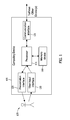
FIG. 1 is a block diagram of an exemplary computing device that may be used to monitor and/or control the operation of a portion of an electric power system. -
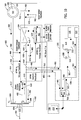
FIG. 2 is block diagram of a portion of an exemplary electric power system protection and control system. -
FIG. 3 is a schematic view of an exemplary wind turbine. -
FIG. 4 is a schematic view of an exemplary electric power system for a doubly fed induction generator (DFIG) that may be used with the wind turbine shown inFIG. 3 . -
FIG. 5 is a schematic view of an exemplary auxiliary electric power system that may be used with the electric power system shown inFIG. 4 . -
FIG. 6 is a schematic view of an exemplary motor-generator set that may be used with the auxiliary electric power system shown inFIG. 5 . -
FIG. 7 is a schematic view of an exemplary alternative motor-generator set that may be used with the auxiliary electric power system shown inFIG. 5 . -
FIG. 8 is a schematic view of another exemplary alternative motor-generator set that may be used with the auxiliary electric power shown in systemFIG. 5 . -
FIG. 9 is a schematic view of yet another exemplary alternative motor-generator set that may be used with the auxiliary electric power system shown inFIG. 5 . -
FIG. 10 is a schematic view of an exemplary alternative electric power system that may be used with the wind turbine shown inFIG. 3 that may use the auxiliary electric power system shown inFIG. 5 . -
FIG. 11 is a schematic view of an exemplary alternative electric power system and exemplary alternative auxiliary electric power system that may be used with an exemplary alternative wind turbine. - As used herein, the term "blade" is intended to be representative of any device that provides reactive force when in motion relative to a surrounding fluid. As used herein, the term "wind turbine" is intended to be representative of any device that generates rotational energy from wind energy, and more specifically, converts kinetic energy of wind into mechanical energy. As used herein, the term "wind turbine generator" is intended to be representative of any wind turbine that generates electrical power from rotational energy generated from wind energy, and more specifically, converts mechanical energy converted from kinetic energy of wind to electrical power.
- As used herein, the terms "disturbance," "grid disturbance," "fault," "system fault," "transient" and other similar terms generally refer to any event that causes perturbations in the input signal from the electric/power grid. For example, such disturbances can include impulses, notches, glitches, momentary interruptions, voltage sag/swells, harmonic distortions, and flickers. Generally, the grid signal is a three-phase signal that includes sequence components having particular frequencies. The three-phase signal includes positive sequence components, negative sequence components, and zero or neutral sequence components. Each of the components includes frequency information, phase information, and magnitude information. As a variety of generating facilities contribute to the grid signal, and as a variety of phenomena including transient events occur, the sequence components may develop harmonic frequencies or phase shifts, either one that can create disturbances which can complicate efficient operation of control systems and/or decrease other aspects of grid performance.
- Many technical effects of the methods, apparatus, and systems described herein include at least one of: (a) using motor-generator (m-g) sets to provide auxiliary electric power to auxiliary equipment within a predetermined voltage range throughout the range of operation of a wind turbine, including those periods when the wind turbine generator is removed from service and/or during electric transients on the electric power grid; (b) using the momentum in m-g sets to facilitate extended generation of auxiliary electric power to auxiliary equipment within a predetermined voltage range; (c) facilitating extending the range of ratings of auxiliary electric power systems and associated wind turbine generators to comply with grid regulations in a plurality of jurisdictions and countries; (d) facilitating extending the range of ratings of auxiliary electric power systems and associated wind turbine generators to be compatible with a plurality of grid strengths and reliabilities; (e) facilitating coupling of wind turbines generators to series compensated transmission lines by compensating for grid voltage transients that may be exacerbated by associated series capacitors; (f) reducing the need for and/or frequency of operation of tap changers on the main power transformers and auxiliary power transformers; and, (g) enhancing HVRT/LVRT/ZVRT capabilities and performance of wind turbines.
- The methods, apparatus, and systems described herein facilitate using motor-generator (m-g) sets to provide auxiliary electric power to auxiliary equipment within predetermined voltage ranges throughout the range of operation of a wind turbine. Specifically, the methods, apparatus, and systems described herein facilitate such auxiliary electric power supply during periods that include when the wind turbine generator is removed from service and/or during electric transients on the electric power grid. More specifically, the methods, apparatus, and systems described herein facilitate using the momentum in m-g sets to facilitate extended generation of auxiliary electric power to auxiliary equipment within a predetermined voltage range during voltage transients on the grid. Also, specifically, the m-g sets facilitate extending the flexibility for adapting auxiliary electric power systems and associated wind turbine generators to comply with to an extended range of ratings of grid regulations in a plurality of jurisdictions and countries, thereby facilitating extending the range of ratings of auxiliary electric power systems and associated wind turbine generators to be compatible with a plurality of grid strengths and reliabilities, including those grids with series compensated transmission lines. Such flexibility reduces the costs of the auxiliary equipment by facilitating use of standard auxiliary support equipment with standard voltage tolerance ratings, rather than using more expensive auxiliary support equipment that is fully complimentary to the extended voltage ranges of the associated electrical grid. Furthermore, such flexibility facilitates reducing the need for and/or frequency of operation of tap changers on the main power transformers and auxiliary power transformers during HVRT/LVRT/ZVRT transients.
- Moreover, the methods, apparatus, and systems described herein include the use of a variety of m-g set types, including induction motors and permanent-magnet motors with and without starters coupled to permanent-magnet generators with and without voltage regulators. Therefore, the methods, apparatus, and systems described herein facilitate eliminating a need for specialized hardware, thereby decreasing construction costs and operational and maintenance costs.
- Although generally described herein with respect to a wind turbine facility, the systems described herein are applicable to any type of electric generation system including, for example, solar power generation systems, fuel cells, geothermal generators, hydropower generators, and/or other devices that generate power from renewable and/or non-renewable energy sources.
-
FIG. 1 is a block diagram of anexemplary computing device 105 that may be used to monitor and/or control the operation of a portion of an auxiliary electric power system (not shown inFIG. 1 ).Computing device 105 includes amemory device 110 and aprocessor 115 operatively coupled tomemory device 110 for executing instructions. As used herein, the term "processor" includes any suitable programmable circuit such as, without limitation, one or more systems and microcontrollers, microprocessors, a general purpose central processing unit (CPU), reduced instruction set circuits (RISC), application specific integrated circuits (ASIC), programmable logic circuits (PLC), field programmable gate arrays (FPGA), and/or any other circuit capable of executing the functions described herein. The above examples are exemplary only, and thus are not intended to limit in any way the definition and/or meaning of the term "processor." -
Processor 115 may include one or more processing units (e.g., in a multi-core configuration). In some embodiments, executable instructions are stored inmemory device 110.Computing device 105 is configurable to perform one or more operations described herein byprogramming processor 115. For example,processor 115 may be programmed by encoding an operation as one or more executable instructions and providing the executable instructions inmemory device 110. - In addition, in the exemplary embodiment,
memory device 110 is at least one device coupled toprocessor 115 that enables storage and retrieval of information such as computer-executable instructions and data, including, without limitation, operating data, parameters, setpoints, threshold values, and/or any other data that enablescomputing device 105 to function as described herein.Memory device 110 may include one or more tangible, non-transitory, computer readable media, such as, without limitation, random access memory (RAM), dynamic random access memory (DRAM), static random access memory (SRAM), a solid state disk, a hard disk, read-only memory (ROM), erasable programmable ROM (EPROM), electrically erasable programmable ROM (EEPROM), and/or non-volatile RAM (NVRAM) memory. The above memory types are exemplary only, and are thus not limiting as to the types of memory usable for storage of a computer program. - Further, as used herein, the terms "software" and "firmware" are interchangeable, and include any computer program stored in memory for execution by personal computers, workstations, clients and servers.
-
Memory device 110 may be configured to store operational measurements including, without limitation, utility electric power grid voltage and current readings (not shown inFIG. 1 ), substation voltage and current readings (not shown inFIG. 1 ), localized voltage and current readings throughout an electric power system, including an auxiliary electric power system and an electric power generation system (both not shown inFIG. 1 ), and/or any other type of data. In some embodiments,processor 115 removes or "purges" data frommemory device 110 based on the age of the data. For example,processor 115 may overwrite previously recorded and stored data associated with a subsequent time and/or event. In addition, or alternatively,processor 115 may remove data that exceeds a predetermined time interval. Also,memory device 110 includes, without limitation, sufficient data, algorithms, and commands to facilitate centralized and distributed control of electric power system protection and control systems (discussed further below). - In some embodiments,
computing device 105 includes apresentation interface 120 coupled toprocessor 115.Presentation interface 120 presents information, such as a user interface and/or an alarm, to auser 125. In one embodiment,presentation interface 120 includes a display adapter (not shown) that is coupled to a display device (not shown), such as a cathode ray tube (CRT), a liquid crystal display (LCD), an organic LED (OLED) display, and/or an "electronic ink" display. In some embodiments,presentation interface 120 includes one or more display devices. In addition, or alternatively,presentation interface 120 includes an audio output device (not shown) (e.g., an audio adapter and/or a speaker) and/or a printer (not shown). In some embodiments,presentation interface 120 presents an alarm associated with a synchronous machine (not shown inFIG. 1 ), such as by using a human machine interface (HMI) (not shown). - In some embodiments,
computing device 105 includes auser input interface 130. In the exemplary embodiment,user input interface 130 is coupled toprocessor 115 and receives input fromuser 125.User input interface 130 may include, for example, a keyboard, a pointing device, a mouse, a stylus, a touch sensitive panel (e.g., a touch pad or a touch screen), and/or an audio input interface (e.g., including a microphone). A single component, such as a touch screen, may function as both a display device ofpresentation interface 120 anduser input interface 130. - A
communication interface 135 is coupled toprocessor 115 and is configured to be coupled in communication with one or more other devices, such as a sensor or anothercomputing device 105, and to perform input and output operations with respect to such devices. For example,communication interface 135 may include, without limitation, a wired network adapter, a wireless network adapter, a mobile telecommunications adapter, a serial communication adapter, and/or a parallel communication adapter.Communication interface 135 may receive data from and/or transmit data to one or more remote devices. For example, acommunication interface 135 of onecomputing device 105 may transmit an alarm to thecommunication interface 135 of anothercomputing device 105. -
Presentation interface 120 and/orcommunication interface 135 are both capable of providing information suitable for use with the methods described herein (e.g., touser 125 or another device). Accordingly,presentation interface 120 andcommunication interface 135 may be referred to as output devices. Similarly,user input interface 130 andcommunication interface 135 are capable of receiving information suitable for use with the methods described herein and may be referred to as input devices. -
FIG. 2 is block diagram of a portion of an exemplary auxiliary electric power system protection andcontrol system 200 that may be used to monitor and/or operate at least a portion of an auxiliaryelectric power system 205. Auxiliary electric power system protection andcontrol system 200 includes an auxiliary electric power system protection andcontrol system controller 215 that may be coupled toother devices 220 via acommunication network 225. Protection andcontrol system controller 215 may be, without limitation, a substation-level centralized controller, a wind turbine-level centralized controller, and one of a plurality of distributed controllers. Embodiments ofnetwork 225 may include operative coupling with, without limitation, the Internet, a local area network (LAN), a wide area network (WAN), a wireless LAN (WLAN), and/or a virtual private network (VPN). While certain operations are described below with respect toparticular computing devices 105, it is contemplated that anycomputing device 105 may perform one or more of the described operations. For example,controller 215 may perform all of the operations below. - Referring to
FIGs. 1 and2 ,controller 215 is acomputing device 105. In the exemplary embodiment,computing device 105 is coupled tonetwork 225 viacommunication interface 135. In an alternative embodiment,controller 215 is integrated withother devices 220. As used herein, the term "computer" and related terms, e.g., "computing device", are not limited to integrated circuits referred to in the art as a computer, but broadly refers to a microcontroller, a microcomputer, a programmable logic controller (PLC), an application specific integrated circuit, and other programmable circuits (none shown inFIG. 2 ), and these terms are used interchangeably herein. -
Controller 215 interacts with a first operator 230 (e.g., viauser input interface 130 and/or presentation interface 120). In one embodiment,controller 215 presents information about auxiliaryelectric power system 205, such as alarms, tooperator 230.Other devices 220 interact with a second operator 235 (e.g., viauser input interface 130 and/or presentation interface 120). For example,other devices 220 present alarms and/or other operational information tosecond operator 235. As used herein, the term "operator" includes any person in any capacity associated with operating and maintaining auxiliaryelectric power system 205, including, without limitation, shift operations personnel, maintenance technicians, and system supervisors. - In the exemplary embodiment, protection and
control system 200 includes one ormore monitoring sensors 240.Monitoring sensors 240 collect operational measurements including, without limitation, voltage and current readings throughout auxiliaryelectric power system 205, including, without limitation, utility electric power grid voltage and current readings (not shown inFIGs. 1 and2 ), substation voltage and current readings (not shown inFIGs. 1 and2 ), localized voltage and current readings throughout an electric power system, including auxiliaryelectric power system 205 and an electric power generation system (not shown inFIGs. 1 and2 ), and/or any other type of data.Monitoring sensors 240 repeatedly (e.g., periodically, continuously, and/or upon request) transmit operational measurement readings at the time of measurement.Controller 215 receives and processes the operational measurement readings. Also,controller 215 includes, without limitation, sufficient data, algorithms, and commands to facilitate centralized and/or distributed protection and control of auxiliary electric power system 205 (discussed further below). - Also, in the exemplary embodiment, auxiliary
electric power system 205 includes additional monitoring sensors (not shown) similar tomonitoring sensors 240 that collect operational data measurements associated with the remainder of auxiliaryelectric power system 205 including, without limitation, data from additional devices similar tocontroller 215 and environmental data, including, without limitation, local outside temperatures. Such data is transmitted acrossnetwork 225 and may be accessed by any device capable of accessingnetwork 225 including, without limitation, desktop computers, laptop computers, and personal digital assistants (PDAs) (neither shown). - The methods described herein may be encoded as executable instructions and algorithms embodied in a tangible, non-transitory, computer readable medium, including, without limitation, a storage device and/or a memory device. Such instructions and algorithms, when executed by a processor, cause the processor to perform at least a portion of the methods described herein. Moreover, as used herein, the term "non-transitory computer-readable media" includes all tangible, computer-readable media, such as a firmware, physical and virtual storage, CD-ROMs, DVDs and another digital source such as a network or the Internet, as well as yet to be developed digital means, with the sole exception being a transitory, propagating signal.
-
FIG. 3 is a schematic view of an exemplarywind turbine generator 300.Wind turbine generator 300 is an electric power generation device including anacelle 302 housing a generator (not shown inFIG. 3 ).Nacelle 302 is mounted on a tower 304 (a portion oftower 304 being shown inFIG. 3 ).Tower 304 may be any height that facilitates operation ofwind turbine generator 300 as described herein.Wind turbine generator 300 also includes arotor 306 that includes threerotor blades 308 attached to arotating hub 310. Alternatively,wind turbine generator 300 includes any number ofblades 308 that facilitates operation ofwind turbine generator 300 as described herein. In the exemplary embodiment,wind turbine generator 300 includes a gearbox (not shown inFIG. 3 ) rotatably coupled torotor 306 and the generator. -
FIG. 4 is a schematic view of an exemplaryelectric power system 400 that may be used withwind turbine 300.Rotor 306 includes plurality ofrotor blades 308 coupled torotating hub 310.Rotor 306 also includes a low-speed shaft 312 rotatably coupled tohub 310. Low-speed shaft is coupled to a step-upgearbox 314.Gearbox 314 is configured to step up the rotational speed of low-speed shaft 312 and transfer that speed to a high-speed shaft 316. In the exemplary embodiment,gearbox 314 can have a step-up ratio of approximately 70:1. For example, low-speed shaft 312 rotating at approximately 20 revolutions per minute (20) coupled togearbox 314 with an approximately 70:1 step-up ratio generates a high-speed shaft 316 speed of approximately 1400 rpm. Alternatively,gearbox 314 has any step-up ratio that facilitates operation ofwind turbine 300 as described herein. Also, alternatively,wind turbine 300 includes a direct-drive generator wherein a generator rotor (not shown inFIG. 4 ) is rotatingly coupled torotor 306 without any intervening gearbox. - High-
speed shaft 316 is rotatably coupled to agenerator 318. In the exemplary embodiment,generator 318 is a wound rotor, synchronous, 60 Hz, three-phase, doubly-fed induction generator (DFIG) that includes agenerator stator 320 magnetically coupled to agenerator rotor 322. Alternatively,generator 318 is any generator of any number of phases that facilitates operation ofwind turbine 300 as described herein. -
Electric power system 400 is a three-phase system and includes acontroller 402.Controller 402 is any processing device that enables operation ofelectric power system 400 as described herein, including, without limitation, controller 215 (shown inFIG. 2 ). Processors forcontroller 402 process information transmitted from a plurality of electrical and electronic devices that may include, but not be limited to, speed and power transducers, current transformers and/or current transducers, breaker position indicators, potential transformers and/or voltage transducers, and the like. -
Electric power system 400 also includesgenerator rotor tachometer 404 that is coupled in electronic data communication withgenerator 318 andcontroller 402.Generator stator 320 is electrically coupled to astator synchronizing switch 406 via astator bus 408. In the exemplary embodiment, to facilitate the DFIG configuration,generator rotor 322 is electrically coupled to a bi-directional electricpower conversion assembly 410 via arotor bus 412. Alternatively,system 400 is configured as a full power conversion system (not shown), wherein a full power conversion assembly (not shown) that is similar in design and operation to electricpower conversion assembly 410 is electrically coupled tostator 320 and such full power conversion assembly facilitates channeling electrical power betweenstator 320 and an electric power transmission and distribution grid (not shown).Stator bus 408 transmits three-phase power fromstator 320 androtor bus 412 transmits three-phase power fromrotor 322 to electricpower conversion assembly 410.Stator synchronizing switch 406 is electrically coupled to a maintransformer circuit breaker 414 via asystem bus 416. - Electric
power conversion assembly 410 includes arotor filter 418 that is electrically coupled torotor 322 viarotor bus 412.Rotor filter 418 is electrically coupled to a rotor-side,bi-directional power converter 420 via arotor filter bus 419.Converter 420 is electrically coupled to a line-side,bi-directional power converter 422.Converters Power converter 422 is electrically coupled to aline filter 424 and aline contactor 426 via a line-sidepower converter bus 423 and aline bus 425. In the exemplary embodiment,converters FIG. 4 ) that "fire" as is known in the art. Alternatively,converters system 400 as described herein.Assembly 410 is coupled in electronic data communication withcontroller 402 to control the operation ofconverters -
Line contactor 426 is electrically coupled to aconversion circuit breaker 428 via a conversioncircuit breaker bus 430.Circuit breaker 428 is also electrically coupled tosystem circuit breaker 414 viasystem bus 416 andconnection bus 432.System circuit breaker 414 is electrically coupled to an electric powermain transformer 434 via a generator-side bus 436.Main transformer 434 is electrically coupled to agrid circuit breaker 438 via a breaker-side bus 440.Grid breaker 438 is connected to an electric power transmission and distribution grid via agrid bus 442. - In the exemplary embodiment,
converters converters FIG. 4 ). DC link 444 includes apositive rail 446, anegative rail 448, and at least onecapacitor 450 coupled therebetween. Alternatively,capacitor 450 is one or more capacitors configured in series or in parallel betweenrails -
Electric power system 400 may further include a phase-locked loop (PLL)regulator 451 that is configured to receive a plurality of voltage measurement signals from a plurality ofvoltage transducers 452. In the exemplary embodiment, each of threevoltage transducers 452 are electrically coupled to each one of the three phases ofbus 442. Alternatively,voltage transducers 452 are electrically coupled tosystem bus 416. Also, alternatively,voltage transducers 452 are electrically coupled to any portion ofsystem 400 that facilitates operation ofsystem 400 as described herein.PLL regulator 451 is coupled in electronic data communication withcontroller 402 andvoltage transducers 452 via a plurality ofelectrical conduits 454. Alternatively,PLL regulator 451 is configured to receive any number of voltage measurement signals from any number ofvoltage transducers 452, including, but not limited to, one voltage measurement signal from onevoltage transducer 452.Controller 402 can also receive any number of current feedbacks from current transformers or current transducers that are electrically coupled to any portion ofsystem 400 that facilitates operation ofsystem 400 as described herein such as, for example, and without limitation, stator current feedback fromstator bus 408, grid current feedback fromgenerator side bus 436. - During operation,
wind impacts blades 308 andblades 308 transform mechanical wind energy into a mechanical rotational torque that rotatingly drives low-speed shaft 312 viahub 310. Low-speed shaft 312 drivesgearbox 314 that subsequently steps up the low rotational speed ofshaft 312 to drive high-speed shaft 316 at an increased rotational speed.High speed shaft 316 rotatingly drivesrotor 322. A rotating magnetic field is induced withinrotor 322 and a voltage is induced withinstator 320 that is magnetically coupled torotor 322.Generator 318 converts the rotational mechanical energy to a sinusoidal, three-phase alternating current (AC) electrical energy signal instator 320. The associated electrical power is transmitted tomain transformer 434 viabus 408,switch 406,bus 416,breaker 414 andbus 436.Main transformer 434 steps up the voltage amplitude of the electrical power and the transformed electrical power is further transmitted to a grid viabus 440,circuit breaker 438 andbus 442. - In the doubly-fed induction generator configuration, a second electrical power transmission path is provided. Electrical, three-phase, sinusoidal, AC power is generated within
wound rotor 322 and is transmitted toassembly 410 viabus 412. Withinassembly 410, the electrical power is transmitted torotor filter 418 wherein the electrical power is modified for the rate of change of the PWM signals associated withconverter 420.Converter 420 acts as a rectifier and rectifies the sinusoidal, three-phase AC power to DC power. The DC power is transmitted intoDC link 444.Capacitor 450 facilitates mitigating DC link 444 voltage amplitude variations by facilitating mitigation of a DC ripple associated with AC rectification. - The DC power is subsequently transmitted from DC link 444 to
power converter 422 whereinconverter 422 acts as an inverter configured to convert the DC electrical power from DC link 444 to three-phase, sinusoidal AC electrical power with predetermined voltages, currents, and frequencies. This conversion is monitored and controlled viacontroller 402. The converted AC power is transmitted fromconverter 422 tobus 416 viabuses line contactor 426,bus 430,circuit breaker 428, andbus 432.Line filter 424 compensates or adjusts for harmonic currents in the electric power transmitted fromconverter 422.Stator synchronizing switch 406 is configured to close such that connecting the three-phase power fromstator 320 with the three-phase power fromassembly 410 is facilitated. -
Circuit breakers system 400. Additional protection components are also provided, includingline contactor 426, which may be controlled to form a disconnect by opening a switch (not shown inFIG. 4 ) corresponding to each of the lines of theline bus 430. -
Assembly 410 compensates or adjusts the frequency of the three-phase power fromrotor 322 for changes, for example, in the wind speed athub 310 andblades 308. Therefore, in this manner, mechanical and electrical rotor frequencies are decoupled and the electrical stator and rotor frequency matching is facilitated substantially independently of the mechanical rotor speed. - Also, in the exemplary embodiment,
electric power system 400 includes auxiliaryelectric power system 205 that includes auxiliary electric power system protection andcontrol system 200 and associated auxiliary electric power system protection andcontrol system controller 215.Controller 215 is coupled to, and controls the operation of, auxiliaryelectric power system 205 that facilitates transmission of electric power to auxiliary systems and devices, e.g., and without limitation, lubrication pumping devices, tower hoisting equipment, lighting systems, uninterruptible power supplies, and in some embodiments, some control systems for electricpower conversion assembly 410 andDFIG 318.System 205 is coupled toconnection bus 432 through a plurality ofelectrical conduits 456. - In the exemplary embodiment,
controller 215 is a portion of a distributed control scheme, wherein, in some embodiments,controller 215 is a de-centralized controller for auxiliaryelectric power system 205 and auxiliary electric power system protection andcontrol system 200. Alternatively,controller 215 is a centralized controller for the entirety ofelectric power system 400. Furthermore, auxiliary electric power system protection andcontrol system 200 includes at least one monitoring sensor 240 (shown inFIG. 2 ) coupled to various devices to collect operational measurements including, without limitation, voltage and current readings throughout auxiliaryelectric power system 205, including, without limitation, utility electricpower grid bus 442 voltage and current readings through a plurality ofelectrical conduits 458. Also,system 200 may include at least onemonitoring sensor 240 to collect operational measurements including, without limitation, additional voltage and current readings throughout auxiliaryelectric power system 205, including, without limitation, a substation (not shown) voltage and current readings, localized voltage and current readings throughoutelectric power system 400, including auxiliaryelectric power system 205 and an electric power generation system, e.g., without limitation, electricpower conversion assembly 410,DFIG 318, andmain power transformer 434, and/or any other type of data. - In operation, sinusoidal three-phase AC electric power generated by
stator 320 ofDFIG 318 is transmitted to electricpower grid bus 442 throughstator bus 408,stator synchronizing switch 406,line bus 416,main transformer breaker 414, generator-side bus 436,main power transformer 434, breaker-side bus 440, andgrid circuit breaker 438 to electricpower grid bus 442 as shown byarrows 460. - Also, in operation, the relative speeds between
generator rotor 322 andgenerator stator 320 determines operation of electricpower conversion assembly 410. For those circumstances whengenerator rotor 322 is being turned at a speed slower than synchronous speed as defined bygenerator stator 320, i.e., a subsynchronous speed, electricpower conversion assembly 410 excitesgenerator rotor 322 withreactive power 465 transmitted from rotor-side power converter 420 throughrotor bus 412.Generator rotor 322 will then appear to be turning at a synchronous speed with respect togenerator stator 320 andstator 320 will generate the desired, i.e., synchronous frequency,electric power 460 that is transmitted to electricpower grid bus 442 as described above. - For those circumstances when
generator rotor 322 is being turned at synchronous speed, electricpower conversion assembly 410 excitesgenerator rotor 322 withreal power 470 transmitted from rotor-side power converter 420 throughrotor bus 412.Generator stator 320 generateselectric power 460 at the synchronous frequency that is transmitted to electricpower grid bus 442 as described above. - For those circumstances when
generator rotor 322 is being turned at a speed faster than the synchronous speed, i.e., a supersynchronous speed, electricpower conversion assembly 410 excitesgenerator rotor 322 withreactive power 470 transmitted from rotor-side power converter 420 throughrotor bus 412 while at the same time extractingreal power 480 fromgenerator rotor 322 throughrotor bus 412 to rotor-side power converter 420.Generator rotor 322 will then appear to be turning at a synchronous speed with respect togenerator stator 320 andstator 320 will generateelectric power 460 at the synchronous frequency that is transmitted to electricpower grid bus 442 as described above. The frequency ofpower 480 extracted fromgenerator rotor 322 will be converted to the synchronous frequency through electricpower conversion assembly 410 and rotor-generatedelectric power 480 is added to stator-generatedpower 460. - Further, in operation, when
generator rotor 322 is generatingelectric power 460 for transmission togrid bus 442, line-side power converter 422 of electricpower conversion assembly 410 is synchronized with the frequency onsystem bus 416, typically a substantially constant 60 Hertz (Hz). Alternatively, the synchronous frequency is any frequency that enables operation ofelectric power system 400 and auxiliaryelectric power system 205 as described herein, including, without limitation, 50 Hz. Therefore, depending on the frequency requirements, the switching devices of line-side power converter 422 are switching at a switching rate that enables a synchronous frequency of either 50 Hz or 60 Hz. - Also, during such operation in subsynchronous, synchronous, and supersynchronous modes,
converter controller 402 operates the switching devices in line-side power converter 422 at the predetermined frequency, e.g., 60 Hz, to convert DC power to AC power for transmission to electricpower grid bus 442. As such,controller 402 regulates the inductive properties, and therefore the power losses, ofbuses positive DC rail 446 andnegative DC rail 448 of DC link 444 togrid bus 442 as a function of a measured voltage onDC link 444. - Moreover, in operation, when
DFIG 318 is generating and transmittingelectric power 460 togrid bus 442, a portion ofelectric power 460 is transmitted to auxiliaryelectric power system 205 as shown byarrows 490. Alternatively, whenDFIG 318 is removed from service, auxiliary electric power is transmitted fromgrid bus 442 throughgrid circuit breaker 438,transformer 434,circuit breaker 414 to auxiliaryelectric power system 205 as shown byarrows 495. -
FIG. 5 is a schematic view of exemplary auxiliaryelectric power system 205 that is used withelectric power system 400. Auxiliaryelectric power system 205 includes at least one motor-generator (m/g) set 500 (only one shown) coupled tosystem bus 416 through asupply conduit 502. Auxiliaryelectric power system 205 includes any number of m/g sets 500 that enables operation ofsystem 205 as described herein. M/g set 500 is configured to receive generatedelectric power 490 orgrid power 495, depending on the status of operation ofDFIG 318. M/g set 500 is also configured to generate auxiliaryelectric power 503 having a voltage within a first predetermined range. M/g set 500 may be coupled tocontroller 215 of auxiliary electric power system protection andcontrol system 200. - Auxiliary
electric power system 205 also includes a plurality ofauxiliary load conduits System 205 further includes at least one auxiliary power transformer 508 (only one shown) coupled to at least one ofconduits Auxiliary power transformer 508 is configured to receive auxiliaryelectric power 503 having a voltage within the first predetermined range and generating auxiliaryelectric power 510 having a voltage within a second predetermined range to a plurality ofauxiliary load conduits 512. - Auxiliary
electric power system 205 also includes a plurality ofauxiliary load buses Auxiliary load bus 514 is configured to supply auxiliary loads (not shown) with auxiliaryelectric power 503 with a voltage within the first predetermined range. For example, and without limitation, such loads may include those loads rated for approximately 690 VAC.Auxiliary load buses electric power 510 with a voltage within the second predetermined range. Such loads include, without limitation, those loads rated for one of 400 VAC, 208 VAC, 173 VAC, including single-phase and three-phase AC, e.g., without limitation, hoists, pumps, fans, heaters, and universal power supplies (UPS). Multipleauxiliary power transformers 508 with differing input and output voltage ratings may be cascaded to supply different voltages to the auxiliary loads. - In some alternative embodiments, m/g set 500,
auxiliary power transformer 508,auxiliary load buses electric power 510 toauxiliary power transformer 508 andauxiliary load bus 514 in the second predetermined voltage tolerance range andauxiliary power transformer 508 is configured to transmit auxiliaryelectric power 503 toauxiliary load buses auxiliary power transformer 508 is configured as a step-down transformer in the exemplary embodiment and may be configured as a step-up transformer in alternative embodiments. - In operation, m/g set 500 receives generated
electric power 490 whenDFIG 318 is in service and receivesgrid power 495 whenDFIG 318 is removed from service. M/g set 500 generates auxiliaryelectric power 503 with a frequency of approximately 60 Hz and within the first predetermined voltage tolerance range that includes 690 VAC. Auxiliaryelectric power 503 is transmitted toauxiliary load bus 514 throughconduit 506. Auxiliaryelectric power 503 is also transmitted toauxiliary power transformer 508 that generates and transmits auxiliaryelectric power 510 with a frequency of approximately 60 Hz and within the second predetermined voltage tolerance range that includes at least one of 400 VAC, 208 VAC, and 173 VAC. Alternatively, the first and second predetermined voltage tolerance ranges may include any voltages that enable operation of auxiliaryelectric power system 205 as described herein. - Also, in operation, with circumstances that include
DFIG 318 out of service and gridelectric power 495 transmitted to auxiliaryelectric power system 205, voltages of gridelectric power 495 may vary within a predetermined voltage tolerance range that may be wider than the rated voltage tolerance ranges of the loads powered fromauxiliary load buses electric power 495 fromgrid bus 442 throughmain power transformer 434. In some embodiments,transformer 434 may include devices to mitigate the effects of the voltage excursions ongrid bus 442, e.g., without limitation, tap changers (not shown). However, tap changers may not be sufficiently rapid in operation to mitigate the voltage transients toauxiliary load buses buses grid bus 442. Further,transformer 434 may have no such voltage excursion remediation device and the voltage transients are passed throughtransformer 434 with little to no mitigation. - Therefore, in operation, m/g set 500 receives grid
electric power 495 with the voltage excursions and generates one of auxiliaryelectric power bus 514.Auxiliary power transformer 508 receives either of auxiliaryelectric power buses DFIG 318 is in service and auxiliaryelectric power system 205 is receiving generatedpower 490. - M/g sets 500 either include sufficient embedded regulation features or are coupled to an external controller to regulate the voltage of the electric power supplied to the equipment downstream. For larger and/or extended transients, e.g., LVRT/ZVRT transients, the inherent momentum of m/g set 500 facilitates the energy conversion process within m/g set 500, especially during extended transients. In addition, m/g set 500 facilitates providing
auxiliary load buses -
FIG. 6 is a schematic view of an exemplary motor-generator (m/g) set 520 that may be used with auxiliary electric power system 205 (shown inFIG. 5 ) as m/g set 500. M/g set 520 includes aninduction motor 522 that is coupled to conduit 502 (shown inFIG. 5 ) and is configured to receive generatedelectric power 490 andgrid power 495, depending on the status of operation of DFIG 318 (shown inFIG. 5 ). M/g set 520 also includes a permanent-magnet (p-m)generator 524 rotatably coupled toinduction motor 522.P-m generator 524 generates one of auxiliaryelectric power 503 within the first predetermined voltage tolerance range and auxiliaryelectric power 510 within the second predetermined voltage tolerance range. M/g set 520 generates auxiliaryelectric power electric power system 205 with voltages within the rated tolerance bands for that equipment receiving auxiliaryelectric power electric power -
FIG. 7 is a schematic view of an exemplary alternative motor-generator (m/g) set 530 that may be used with auxiliary electric power system 205 (shown inFIG. 5 ) as m/g set 500. M/g set 530 includesinduction motor 522 that is coupled to conduit 502 (shown inFIG. 5 ) and is configured to receive generatedelectric power 490 andgrid power 495, depending on the status of operation of DFIG 318 (shown inFIG. 5 ). M/g set 530 also includes a permanent-magnet (p-m)generator 534 rotatably coupled toinduction motor 522.P-m generator 534 generates one of auxiliaryelectric power 503 within the first predetermined voltage tolerance range and auxiliaryelectric power 510 within the second predetermined voltage tolerance range.P-m generator 534 includes a voltage regulation controller, i.e.,regulator 536 that may be either one of a stand-alone device or coupled tocontroller 215 of auxiliary electric power system protection andcontrol system 200. M/g set 530 generates auxiliaryelectric power auxiliary power system 205 with voltages within the rated tolerance bands for grids that may have severe or extended voltage transients and operate within relatively broad voltage ranges. Therefore, m/g set 530 withvoltage regulator 536 facilitates operation of loads receiving auxiliaryelectric power -
FIG. 8 is a schematic view of another exemplary alternative motor-generator (m/g) set 540 that may be used with auxiliary electric power system 205 (shown inFIG. 5 ) as m/g set 500. M/g set 540 is similar to m/g set 530 (shown inFIG. 8 ) with the exception that m/g set 540 includes aninduction motor starter 548 coupled toinduction motor 522.Induction motor starter 548 may be either one of a stand-alone device or coupled tocontroller 215 of auxiliary electric power system protection andcontrol system 200. M/g set 540 facilitates continued operation ofauxiliary power system 205 with voltages within the rated tolerance bands for grids that may have severe or extended voltage transients and operate within relatively broad voltage ranges.Induction motor starter 548 facilitates reducing and/or controlling the inrush of current wheninduction motor 522 is placed into service. -
FIG. 9 is a schematic view of yet another exemplary alternative motor-generator (m/g) set 550 that may be used with the auxiliary electric power system shown inFIG. 5 as m/g set 500. M/g set 550 includes a permanent-magnet (p-m)motor 552 that is coupled to conduit 502 (shown inFIG. 5 ) and is configured to receive generatedelectric power 490 andgrid power 495, depending on the status of operation of DFIG 318 (shown inFIG. 5 ). M/g set 550 also includesp-m generator 534 rotatably coupled top-m motor 552.P-m generator 534 includesvoltage regulator 536 that may be either one of a stand-alone device or coupled tocontroller 215 of auxiliary electric power system protection andcontrol system 200. M/g set 550 includes ap-m motor starter 558 coupled top-m motor 552.P-m motor starter 558 may be either one of a stand-alone device or coupled tocontroller 215 of auxiliary electric power system protection andcontrol system 200. M/g set 550 generates auxiliaryelectric power auxiliary power system 205 with voltages within the rated tolerance bands for grids that may have severe or extended voltage transients and operate within relatively broad voltage ranges. Alternative embodiments of m/g set 500 may include, without limitation, p-m generator 524 (shown inFIG. 6 ), i.e., without a voltage regulator.P-m motor 552 facilitates increasing the overall efficiency of m/g set 550. -
FIG. 10 is a schematic view of an exemplary alternativeelectric power system 600 that may be used with wind turbine 300 (shown inFIG. 3 ) that may use auxiliaryelectric power system 205.Electric power system 600 includes an alternativemain power transformer 602 that includes a set ofhigh side windings 604 and two sets of low side windings, i.e., a first set oflow side windings 606 and a second set oflow side windings 608.High side windings 604 are coupled to medium voltage (MV)switchgear 610 that couples and uncouplesgrid bus 442 frommain power transformer 602. Firstlow side windings 606 are coupled tocircuit breaker 414 through a first mainpower transformer bus 612. Also,windings 606 are configured to receiveelectric power 460 fromstator 320 at a first voltage V1. -
Electric power system 600 also includes analternative converter system 614.Converter system 614 includes electricpower conversion assembly 410 coupled torotor 322. Electricpower conversion assembly 410 is also coupled to secondlow side windings 608 through aconduit 615, a plurality ofinductive devices 616, acircuit breaker 618, and aconverter contactor 620 that facilitates removingassembly 410 from service whenDFIG 318 is removed from service.Converter system 614 also includes aconverter control system 622 that receives a variety of feedback signals, regulatesconversion assembly 410, and transmits signals to various other systems, including, without limitation, open and close signals toMV switchgear 610. Rotor-generatedreal power 480 at a second voltage V2 is transmitted togrid bus 442 through secondlow side windings 608 andreal power 470 torotor 322 is transmitted fromgrid bus 442 toconversion assembly 410 throughwindings 608 at V2. Similarly,grid power 495 is transmitted throughwindings 608 toconduit 615 at V2 and generatedpower 480 is transmitted throughconversion assembly 410 toconduit 615.Conduit 615 is coupled to supplyconduit 502 andpower 495 andpower 490 are used in auxiliaryelectric power system 205 as described above. -
Main power transformer 602 and main power transformer 434 (shown inFIG. 5 ) are interchangeable betweensystems conversion assembly 410 andconverter system 614. -
FIG. 11 is a schematic view of an exemplary alternative electric power system and exemplary alternative auxiliaryelectric power system 700 that may be used with an exemplary alternativewind turbine generator 704.Wind turbine generator 704 includeswind turbine blades 308 coupled to arotor 706 that includes alow speed shaft 708 and ahigh speed shaft 710.Wind turbine generator 704 also includes agearbox 712 rotatably coupled tolow speed shaft 708 andhigh speed shaft 710. Agenerator 714 is rotatably coupled tohigh speed shaft 710. In the exemplary embodiment,generator 714 is any type of generator that enables operation ofwind turbine generator 300 as described herein, including, without limitation, a synchronous permanent magnet generator (PMG) and an electrically excited synchronous generator (EESG).Gearbox 712 steps-up a rotational velocity oflow speed shaft 708 to attain a rotational velocity ofhigh speed shaft 710 that is closer to synchronous speed. - Also, in this exemplary alternative embodiment,
electric power system 700 is a three-phase system.Generator 714 includes agenerator stator 716 extending about agenerator rotor 718 that is rotatably coupled tohigh speed shaft 710.Stator 716 is coupled to astator bus 720 through a plurality ofinductive devices 722.Stator bus 720 is coupled to anelectric power converter 724.Electric power converter 724 includes agenerator side portion 726 coupled tostator bus 720.Generator side portion 726 is coupled to aline side portion 728 through aDC link 730. DC link 730 includes at least onecapacitive device 732 coupled to apositive DC bus 734 and anegative DC bus 736.Line side portion 728 is coupled to anAC line bus 738 that includes at least oneinductive device 740.Stator bus 720 transmits three-phase electric power togenerator side portion 726 andAC line bus 738 transmits three-phase electric power away fromline side portion 728. - Each of
generator side portion 726 andline side portion 728 ofelectric power converter 724 includes a plurality ofsemiconductor switching devices 742 coupled together in serial arrangement for each phase of electrical power thatelectric power converter 724 receives, converts, and transmits. In the exemplary embodiment, switchingdevices 742 are semiconductor devices, e.g., insulated gate bipolar transistors (IGBTs), that include base, emitter, and collector portions (not shown) and an inverse, oranti-parallel diode 744. Alternatively, switchingdevices 742 are any other suitable transistor or any other suitable switching device, including, without limitation, gate turn-off thyristors (GTOs). Alternatively,generator side portion 726 andline side portion 728 may include any suitable number of switchingdevices 742 arranged in any suitable configuration. A stator-synchronizingswitch 746 couplesAC line bus 738 to amain power transformer 748 that coupleselectric power system 700 to electricpower grid bus 442 whenswitch 746 is closed.Main power transformer 748 may be similar to one of main power transformer 434 (shown inFIGs. 4 and5 ) and main power transformer 602 (shown inFIG. 10 ). Alternatively,main power transformer 748 has any configuration that enables operation ofelectric power system 700 and auxiliaryelectric power system 702 as described herein. -
Electric power system 700 includes auxiliaryelectric power system 702 that is similar to auxiliary electric power system 205 (shown inFIGs. 2 ,4 ,5 , and10 ). The plurality ofsupply conduits 750 are similar to supply conduit 502 (shown inFIGs. 5 and10 ).Supply conduits 750 transmit generatedreal power 752 andgrid power 754. Operation of auxiliaryelectric power system 702 is substantially similar to that for auxiliaryelectric power system 205. - In some alternative embodiments, a combination of electric power generation devices are used in conjunction with, or in place of,
wind turbine generators wind turbine generator 300/704 is replaced with solar panels (not shown) coupled to form one or more solar arrays (not shown) to facilitate operating at a desired power output with supplemental, solar-generated power. Solar panels include, in one alternative embodiment, one or more of a photovoltaic panel, a solar thermal collector, or any other device that converts solar energy to electrical energy. In such alternative embodiments, each solar panel is a photovoltaic panel that generates a substantially direct current power as a result of solar energy striking solar panels. - Also, in such alternative embodiments, each solar array is coupled to a power converter that is similar to at least a portion of
electric power converter 724 that converts the DC power to AC power that is transmitted to a transformer, similar tomain power transformer 748, and then subsequently togrid bus 442. Furthermore, although generally described herein with respect towind turbine generator 704 and a solar array facility, the methods and systems described herein are applicable to any type of electric generation system, with or without a power converter, including, for example, fuel cells, thermal power generators, geothermal generators, hydropower generators, diesel generators, gasoline generators, and/or any other device that generates power from renewable and/or non-renewable energy sources. - Exemplary embodiments of an electric power generation facility, an electric power system, and an auxiliary electric power system and methods for operating the same are described above in detail. The methods, facilities, systems, and apparatus are not limited to the specific embodiments described herein, but rather, components of the facilities, systems, and apparatus, and/or steps of the methods may be utilized independently and separately from other components and/or steps described herein. For example, auxiliary electric power system and methods may also be used in combination with other power conversion apparatus and methods, and are not limited to practice with only the electric power systems as described herein. Rather, the exemplary embodiment can be implemented and utilized in connection with many other electric power conversion applications.
- Although specific features of various embodiments of the invention may be shown in some drawings and not in others, this is for convenience only. In accordance with the principles of the invention, any feature of a drawing may be referenced and/or claimed in combination with any feature of any other drawing.
- This written description uses examples to disclose the invention, including the preferred, and also to enable any person skilled in the art to practice the invention, including making and using any devices or systems and performing any incorporated methods. The patentable scope of the invention is defined by the claims, and may include other examples that occur to those skilled in the art. Such other examples are intended to be within the scope of the claims if they have structural elements that do not differ from the literal language of the claims, or if they include equivalent structural elements with insubstantial differences from the literal language of the claims.
- Various aspects and embodiments of the present invention are defined by the following numbered clauses:
- 1. An electric power system for a wind turbine, said electric power system comprising:
- at least one auxiliary load bus configured to transmit electric power to auxiliary equipment, said auxiliary load bus further configured to receive electric power having a voltage within a first predetermined tolerance range; and
- at least one motor-generator set coupled to said auxiliary load bus, said motor-generator set configured to receive electric power having a voltage within a second predetermined tolerance range and transmit electric power to said auxiliary load bus in the first predetermined tolerance range.
- 2. The electric power system in accordance with clause 1, further comprising at least one main power transformer coupled to an electric utility grid and said motor-generator set.
- 3. The electric power system in accordance with any preceding clause, further comprising at least one auxiliary power transformer coupled to said motor-generator set and said auxiliary load bus.
- 4. The electric power system in accordance with any preceding clause, wherein:
- said motor-generator set is configured to transmit electric power to said auxiliary power transformer in the first predetermined voltage tolerance range; and
- said auxiliary power transformer is configured to transmit electric power to said auxiliary load bus in a third predetermined voltage tolerance range.
- 5. The electric power system in accordance with any preceding clause, wherein said motor-generator set is configured to transmit electric power to said auxiliary load bus in the first predetermined voltage tolerance range.
- 6. The electric power system in accordance with any preceding clause, wherein said motor-generator set comprises:
- one of an induction motor and a permanent-magnet motor; and
- a permanent-magnet generator coupled to said one of said induction motor and said permanent-magnet motor.
- 7. The electric power system in accordance with any preceding clause, wherein said motor-generator set further comprises an induction motor starter coupled to said induction motor.
- 8. The electric power system in accordance with any preceding clause, wherein said permanent-magnet generator comprises a voltage regulation controller.
- 9. The electric power system in accordance with any preceding clause, wherein said voltage regulation controller comprises:
- at least one processor; and
- at least one non-transitory computer-readable storage media coupled to said processor, said non-transitory computer-readable storage media having computer-executable instructions embodied thereon, wherein when executed by said processor, the computer-executable instructions cause said processor to operate said motor-generator set to regulate the voltage and current transmitted to said auxiliary load bus.
- 10. A renewable energy generation facility comprising:
- at least one electric power doubly-fed induction generator (DFIG); and
- an auxiliary electric power system coupled to said DFIG, said auxiliary electric power system comprising:
- at least one auxiliary load bus configured to receive electric power having a voltage within a first predetermined tolerance range;
- at least one electric power generator auxiliary load coupled to said auxiliary load bus, said auxiliary load bus configured to transmit electric power to said auxiliary load; and
- at least one motor-generator set coupled to said auxiliary load bus, said motor-generator set configured to receive electric power having a voltage within a second predetermined tolerance range and transmit electric power to said auxiliary load bus in the first predetermined tolerance range.
- 11. The renewable energy generation system in accordance with any preceding clause, further comprising at least one main power transformer coupled to an electric utility grid and said motor-generator set.
- 12. The renewable energy generation system in accordance with any preceding clause, further comprising at least one auxiliary power transformer coupled to said motor-generator set and said auxiliary load bus.
- 13. The renewable energy generation system in accordance with any preceding clause, wherein:
- said motor-generator set is configured to transmit electric power to said auxiliary power transformer in the first predetermined voltage tolerance range; and
- said auxiliary power transformer is configured to transmit electric power to said auxiliary load bus in a third predetermined voltage tolerance range.
- 14. The renewable energy generation system in accordance with any preceding clause, wherein said motor-generator set is configured to transmit electric power to said auxiliary load bus in the first predetermined voltage tolerance range.
- 15. The renewable energy generation system in accordance with any preceding clause, wherein said motor-generator set comprises:
- an induction motor; and
- a permanent-magnet generator coupled to said induction motor.
- 16. The renewable energy generation system in accordance with any preceding clause, wherein said at least one motor-generator set further comprises an induction motor starter coupled to said induction motor.
- 17. The renewable energy generation system in accordance with any preceding clause, wherein said permanent-magnet generator comprises a voltage regulation controller.
- 18. The renewable energy generation system in accordance with any preceding clause, wherein said voltage regulation controller comprises:
- at least one processor; and
- at least one non-transitory computer-readable storage media coupled to said processor, said non-transitory computer-readable storage media having computer-executable instructions embodied thereon, wherein when executed by said processor, the computer-executable instructions cause said processor to operate said motor-generator to regulate the voltage and current transmitted to said auxiliary load bus.
- 19. A method for controlling operation of a renewable energy generation system, the renewable energy generation system including a doubly-fed induction generator (DFIG), at least one auxiliary load bus configured to receive electric power having a voltage within a first predetermined tolerance range, said method comprising:
- transmitting electric power from one of the DFIG and an electric utility grid to a motor-generator set, the electric power having a voltage within a second predetermined tolerance range; and
- regulating the motor-generator set to transmit electric power having a voltage within the first predetermined tolerance range to the auxiliary load bus.
- 20. The method in accordance with any preceding clause, further comprising facilitating operation of at least one of a low voltage ride through (LVRT) feature, a zero voltage ride through (ZVRT) feature, and a high voltage ride through (HVRT) feature through converting at least a portion of an inertia of the motor-generator set to electric power transmitted from the motor-generator to the auxiliary load bus.
Claims (15)
- An electric power system (500) for a wind turbine (300), said electric power system (500) comprising:at least one auxiliary load bus (514, 516, 518) configured to transmit electric power to auxiliary equipment, said auxiliary load bus (514, 516, 518) further configured to receive electric power having a voltage within a first predetermined tolerance range; andat least one motor-generator set (500) coupled to said auxiliary load bus (514, 516, 518), said motor-generator set (500) configured to receive electric power having a voltage within a second predetermined tolerance range and transmit electric power to said auxiliary load bus in the first predetermined tolerance range.
- The electric power system (500) in accordance with claim 1, further comprising at least one main power transformer (434) coupled to an electric utility grid and said motor-generator set (500).
- The electric power system in accordance with any preceding claim, further comprising at least one auxiliary power transformer coupled to said motor-generator set and said auxiliary load bus (514, 516, 518).
- The electric power system (500) in accordance with claim 3, wherein:said motor-generator set is configured to transmit electric power to said auxiliary power transformer in the first predetermined voltage tolerance range; andsaid auxiliary power transformer is configured to transmit electric power to said auxiliary load bus in a third predetermined voltage tolerance range.
- The electric power system (500) in accordance with any preceding claim, wherein said motor-generator set (500) is configured to transmit electric power to said auxiliary load bus (514, 516, 518) in the first predetermined voltage tolerance range.
- The electric power system (500) in accordance with any preceding claim, wherein said motor-generator set comprises:one of an induction motor (522 and a permanent-magnet motor (530); anda permanent-magnet generator (524) coupled to said one of said induction motor and said permanent-magnet motor (530).
- The electric power system (500) in accordance with claim 6, wherein said motor-generator set further comprises an induction motor starter coupled to said induction motor (522).
- The electric power system (500) in accordance with claim 6 or claim 7, wherein said permanent-magnet generator (524) comprises a voltage regulation controller (536).
- The electric power system (500) in accordance with claim 8, wherein said voltage regulation controller (536) comprises:at least one processor; andat least one non-transitory computer-readable storage media coupled to said processor, said non-transitory computer-readable storage media having computer-executable instructions embodied thereon, wherein when executed by said processor, the computer-executable instructions cause said processor to operate said motor-generator set to regulate the voltage and current transmitted to said auxiliary load bus.
- A renewable energy generation facility (300) comprising:at least one electric power doubly-fed induction generator (DFIG) (318); andan auxiliary electric power system (205) coupled to said DFIG (318), said auxiliary electric power system comprising:at least one auxiliary load bus (514, 516, 518) configured to receive electric power having a voltage within a first predetermined tolerance range;at least one electric power generator auxiliary load coupled to said auxiliary load bus, said auxiliary load bus configured to transmit electric power to said auxiliary load; andat least one motor-generator set (500) coupled to said auxiliary load bus (514, 516, 518), said motor-generator set configured to receive electric power having a voltage within a second predetermined tolerance range and transmit electric power to said auxiliary load bus in the first predetermined tolerance range.
- The renewable energy generation system (300) in accordance with claim 10, further comprising at least one main power transformer coupled to an electric utility grid and said motor-generator set.
- The renewable energy generation system (300) in accordance with claim 10 or claim 11, further comprising at least one auxiliary power transformer coupled to said motor-generator set and said auxiliary load bus.
- The renewable energy generation system (300) in accordance with any of claims 10 to 12, wherein:said motor-generator set is configured to transmit electric power to said auxiliary power transformer in the first predetermined voltage tolerance range; and,said auxiliary power transformer is configured to transmit electric power to said auxiliary load bus in a third predetermined voltage tolerance range.
- The renewable energy generation system (300) in accordance with any of claims 10 to 13, wherein said motor-generator set is configured to transmit electric power to said auxiliary load bus in the first predetermined voltage tolerance range.
- A method for controlling operation of a renewable energy generation system (300), the renewable energy generation system (300) including a doubly-fed induction generator (DFIG) (318), at least one auxiliary load bus (514, 516, 518) configured to receive electric power having a voltage within a first predetermined tolerance range, said method comprising:transmitting electric power from one of the DFIG (318) and an electric utility grid to a motor-generator set (500), the electric power having a voltage within a second predetermined tolerance range; andregulating the motor-generator set (500) to transmit electric power having a voltage within the first predetermined tolerance range to the auxiliary load bus (514, 516,518).
Applications Claiming Priority (1)
| Application Number | Priority Date | Filing Date | Title |
|---|---|---|---|
| US14/024,044 US9513614B2 (en) | 2013-09-11 | 2013-09-11 | Auxiliary electric power system and method of regulating voltages of the same |
Publications (2)
| Publication Number | Publication Date |
|---|---|
| EP2866323A1 true EP2866323A1 (en) | 2015-04-29 |
| EP2866323B1 EP2866323B1 (en) | 2020-04-01 |
Family
ID=51492847
Family Applications (1)
| Application Number | Title | Priority Date | Filing Date |
|---|---|---|---|
| EP14183620.5A Active EP2866323B1 (en) | 2013-09-11 | 2014-09-04 | Auxiliary electric power system and method of regulating voltages of the same |
Country Status (5)
| Country | Link |
|---|---|
| US (1) | US9513614B2 (en) |
| EP (1) | EP2866323B1 (en) |
| CA (1) | CA2862898C (en) |
| DK (1) | DK2866323T3 (en) |
| ES (1) | ES2802821T3 (en) |
Cited By (1)
| Publication number | Priority date | Publication date | Assignee | Title |
|---|---|---|---|---|
| WO2025131277A1 (en) * | 2023-12-20 | 2025-06-26 | General Electric Renovables España S.L. | Methods for operating wind turbines and wind turbines |
Families Citing this family (20)
| Publication number | Priority date | Publication date | Assignee | Title |
|---|---|---|---|---|
| JP6511224B2 (en) * | 2014-04-23 | 2019-05-15 | 日立オートモティブシステムズ株式会社 | Power supply |
| EP3278447B1 (en) | 2015-04-01 | 2022-02-23 | Vestas Wind Systems A/S | Method for handling an over voltage ride through event and doubly fed induction generator |
| DE102016208051A1 (en) * | 2016-05-10 | 2017-11-16 | Wobben Properties Gmbh | Wind turbine rotor blade, and wind turbine with selbigem |
| US11336098B2 (en) | 2016-06-13 | 2022-05-17 | Vestas Wind Systems A/S | Interconnection of multiple renewable energy power plants |
| EP3504786A1 (en) | 2016-08-26 | 2019-07-03 | Vestas Wind Systems A/S | Control of a wind turbine generator for reduced tonal audibility |
| US9806690B1 (en) * | 2016-09-30 | 2017-10-31 | AEP Transmission Holding Company, LLC | Subsynchronous oscillation relay |
| NL2018325B1 (en) * | 2017-02-07 | 2018-08-29 | Hypnagogia Ug | A vertical axis wind turbine, and method for operating such a wind turbine |
| US10523088B2 (en) * | 2017-04-24 | 2019-12-31 | General Electric Company | Energy storage system for doubly fed induction generator |
| ES2935971T3 (en) * | 2017-12-22 | 2023-03-13 | Ge Renewable Tech Wind Bv | Procedures for supplying electrical power to wind turbine components |
| US10651648B2 (en) | 2018-01-11 | 2020-05-12 | General Electric Company | System for powering auxiliary loads of an energy storage system |
| US10778112B2 (en) * | 2018-04-04 | 2020-09-15 | General Electric Company | DFIG converter with active filter |
| EP3900144A1 (en) * | 2018-12-20 | 2021-10-27 | Vestas Wind Systems A/S | Control of a renewable energy power plant to resume normal operation following a fault |
| EP3742571A1 (en) * | 2019-05-20 | 2020-11-25 | Siemens Gamesa Renewable Energy A/S | Method and arrangement for controlling an energy storage device |
| US11736056B2 (en) * | 2019-05-30 | 2023-08-22 | General Electric Company | System and method for controlling harmonics in a renewable energy power system |
| EP3767771A1 (en) * | 2019-07-17 | 2021-01-20 | Siemens Aktiengesellschaft | Method for producing inductive idle power by means of an electric consumer device, electric consumer device and electrolysis device |
| US11486360B2 (en) | 2020-04-10 | 2022-11-01 | General Electric Company | System and method for controlling wind turbine converters during high voltage ride through events |
| EP3989382A1 (en) * | 2020-10-26 | 2022-04-27 | Siemens Gamesa Renewable Energy Innovation & Technology S.L. | Wind turbine auxiliary power system |
| DK181000B9 (en) * | 2021-03-05 | 2022-09-15 | Scada Int A/S | A monitoring system for wind turbines, use of such a monitoring system, a wind farm comprising such a monitoring system, a method for monitoring the operation of a number of wind turbines, and a computer program product configured to carry out such a method |
| CN116365570A (en) * | 2021-12-28 | 2023-06-30 | 北京金风科创风电设备有限公司 | Power transmission and transformation system and wind power generating set including the power transmission and transformation system |
| CN117239670B (en) * | 2023-11-14 | 2024-01-26 | 昆明理工大学 | A single-phase adaptive reclosing method and system for wind power AC transmission lines |
Citations (6)
| Publication number | Priority date | Publication date | Assignee | Title |
|---|---|---|---|---|
| WO2003106828A2 (en) * | 2002-06-18 | 2003-12-24 | Ingersoll-Rand Energy Systems Corporation | Microturbine engine system |
| US20040145188A1 (en) * | 2003-01-24 | 2004-07-29 | Wilhelm Janssen | Low voltage ride through for wind turbine generators |
| EP1804372A2 (en) * | 2005-12-30 | 2007-07-04 | Korea Electro Technology Research Institute | Electric power converting device and power converting method for controlling doubly-fed induction generator |
| WO2011019321A2 (en) * | 2009-08-14 | 2011-02-17 | Vestas Wind Systems A/S | A variable speed wind turbine, and a method for operating the variable speed wind turbine during a power imbalance event |
| CN102709906A (en) * | 2012-05-14 | 2012-10-03 | 南方电网科学研究院有限责任公司 | Frequency layered coordinated control method for isolated microgrid with diesel storage |
| US20130229056A1 (en) * | 2012-03-05 | 2013-09-05 | Ralph Teichmann | Auxiliary equipment system and method of operating the same |
Family Cites Families (11)
| Publication number | Priority date | Publication date | Assignee | Title |
|---|---|---|---|---|
| GB456197A (en) * | 1935-11-25 | 1936-11-04 | Frank Whyman | Improvements relating to electrically driven locomotives |
| US4256972A (en) * | 1979-05-10 | 1981-03-17 | Beckwith Electric Co., Inc. | Power transfer relay circuitry and method of phase measurement |
| JPS5928871A (en) * | 1982-08-05 | 1984-02-15 | Shoji Hatakeyama | Mechanism with power machine for operating driven unit by principle of loading-back method |
| US4442385A (en) * | 1983-02-10 | 1984-04-10 | Power Distribution, Inc. | Variable frequency drive for a motor-generator/alternator set |
| GB2275377B (en) * | 1993-02-22 | 1997-05-28 | Yang Tai Her | An electric energy generation and storage apparatus |
| US7015595B2 (en) | 2002-02-11 | 2006-03-21 | Vestas Wind Systems A/S | Variable speed wind turbine having a passive grid side rectifier with scalar power control and dependent pitch control |
| GB0312378D0 (en) * | 2003-05-30 | 2003-07-02 | Owen Michael | Electro-mechanical rotary power converter |
| CN101227136A (en) * | 2007-01-16 | 2008-07-23 | 林冈嵚 | Independent self-free type integral compound excitation automatic ring-gathering synchronous magnetic energy power generator |
| EP2302755B1 (en) * | 2009-09-29 | 2012-11-28 | OpenHydro IP Limited | An electrical power conversion system and method |
| EP2565443A1 (en) * | 2011-09-05 | 2013-03-06 | XEMC Darwind B.V. | Generating auxiliary power for a wind turbine |
| US20140252774A1 (en) * | 2013-01-23 | 2014-09-11 | Paul Boaventura-Delanoe | Wind, solar, and magnetic electrical generation system |
-
2013
- 2013-09-11 US US14/024,044 patent/US9513614B2/en active Active
-
2014
- 2014-09-04 CA CA2862898A patent/CA2862898C/en active Active
- 2014-09-04 EP EP14183620.5A patent/EP2866323B1/en active Active
- 2014-09-04 DK DK14183620.5T patent/DK2866323T3/en active
- 2014-09-04 ES ES14183620T patent/ES2802821T3/en active Active
Patent Citations (6)
| Publication number | Priority date | Publication date | Assignee | Title |
|---|---|---|---|---|
| WO2003106828A2 (en) * | 2002-06-18 | 2003-12-24 | Ingersoll-Rand Energy Systems Corporation | Microturbine engine system |
| US20040145188A1 (en) * | 2003-01-24 | 2004-07-29 | Wilhelm Janssen | Low voltage ride through for wind turbine generators |
| EP1804372A2 (en) * | 2005-12-30 | 2007-07-04 | Korea Electro Technology Research Institute | Electric power converting device and power converting method for controlling doubly-fed induction generator |
| WO2011019321A2 (en) * | 2009-08-14 | 2011-02-17 | Vestas Wind Systems A/S | A variable speed wind turbine, and a method for operating the variable speed wind turbine during a power imbalance event |
| US20130229056A1 (en) * | 2012-03-05 | 2013-09-05 | Ralph Teichmann | Auxiliary equipment system and method of operating the same |
| CN102709906A (en) * | 2012-05-14 | 2012-10-03 | 南方电网科学研究院有限责任公司 | Frequency layered coordinated control method for isolated microgrid with diesel storage |
Cited By (1)
| Publication number | Priority date | Publication date | Assignee | Title |
|---|---|---|---|---|
| WO2025131277A1 (en) * | 2023-12-20 | 2025-06-26 | General Electric Renovables España S.L. | Methods for operating wind turbines and wind turbines |
Also Published As
| Publication number | Publication date |
|---|---|
| EP2866323B1 (en) | 2020-04-01 |
| DK2866323T3 (en) | 2020-07-13 |
| US9513614B2 (en) | 2016-12-06 |
| CA2862898C (en) | 2021-12-07 |
| CA2862898A1 (en) | 2015-03-11 |
| US20150073610A1 (en) | 2015-03-12 |
| ES2802821T3 (en) | 2021-01-21 |
Similar Documents
| Publication | Publication Date | Title |
|---|---|---|
| EP2866323B1 (en) | Auxiliary electric power system and method of regulating voltages of the same | |
| EP2873151B1 (en) | Electric power system and method of operating the same | |
| US8519568B2 (en) | Inrush current protection for wind turbines and wind farms | |
| US9077205B2 (en) | Auxiliary equipment system and method of operating the same | |
| US7843078B2 (en) | Method and apparatus for generating power in a wind turbine | |
| EP2704309A2 (en) | System and method for controlling a dual-fed induction generator in response to high-voltage grid events | |
| US9577557B2 (en) | Turbine-generator system with DC output | |
| EP3096005B1 (en) | Limit for derating scheme used in wind turbine control | |
| US20130138257A1 (en) | System for operating an electric power system and method of operating the same | |
| US8854845B2 (en) | System and method of over-voltage protection | |
| US9494139B2 (en) | System and method for controlling a power output of a wind turbine generator | |
| US10218298B2 (en) | Spillover of reactive current to line side converter | |
| US20150263508A1 (en) | System and method for detecting islanding of electrical machines and protecting same | |
| Samoylenko et al. | Semiconductor power electronics for synchronous distributed generation | |
| Tourou et al. | Performance analysis of doubly fed induction generators operating in weak power systems | |
| JP2018121476A (en) | Wind power generation facility and method for operating the same |
Legal Events
| Date | Code | Title | Description |
|---|---|---|---|
| PUAI | Public reference made under article 153(3) epc to a published international application that has entered the european phase |
Free format text: ORIGINAL CODE: 0009012 |
|
| 17P | Request for examination filed |
Effective date: 20140904 |
|
| AK | Designated contracting states |
Kind code of ref document: A1 Designated state(s): AL AT BE BG CH CY CZ DE DK EE ES FI FR GB GR HR HU IE IS IT LI LT LU LV MC MK MT NL NO PL PT RO RS SE SI SK SM TR |
|
| AX | Request for extension of the european patent |
Extension state: BA ME |
|
| R17P | Request for examination filed (corrected) |
Effective date: 20151029 |
|
| RBV | Designated contracting states (corrected) |
Designated state(s): AL AT BE BG CH CY CZ DE DK EE ES FI FR GB GR HR HU IE IS IT LI LT LU LV MC MK MT NL NO PL PT RO RS SE SI SK SM TR |
|
| 17Q | First examination report despatched |
Effective date: 20160120 |
|
| STAA | Information on the status of an ep patent application or granted ep patent |
Free format text: STATUS: EXAMINATION IS IN PROGRESS |
|
| GRAP | Despatch of communication of intention to grant a patent |
Free format text: ORIGINAL CODE: EPIDOSNIGR1 |
|
| STAA | Information on the status of an ep patent application or granted ep patent |
Free format text: STATUS: GRANT OF PATENT IS INTENDED |
|
| INTG | Intention to grant announced |
Effective date: 20190429 |
|
| GRAJ | Information related to disapproval of communication of intention to grant by the applicant or resumption of examination proceedings by the epo deleted |
Free format text: ORIGINAL CODE: EPIDOSDIGR1 |
|
| STAA | Information on the status of an ep patent application or granted ep patent |
Free format text: STATUS: EXAMINATION IS IN PROGRESS |
|
| INTC | Intention to grant announced (deleted) | ||
| GRAP | Despatch of communication of intention to grant a patent |
Free format text: ORIGINAL CODE: EPIDOSNIGR1 |
|
| STAA | Information on the status of an ep patent application or granted ep patent |
Free format text: STATUS: GRANT OF PATENT IS INTENDED |
|
| INTG | Intention to grant announced |
Effective date: 20191018 |
|
| RIN1 | Information on inventor provided before grant (corrected) |
Inventor name: WILMOT, THEODORE STEVEN Inventor name: SCHNETZKA, HAROLD ROBERT Inventor name: VUJAOVIC, BRANISLAV Inventor name: JAYKO, TIMOTHY WILCOX |
|
| GRAS | Grant fee paid |
Free format text: ORIGINAL CODE: EPIDOSNIGR3 |
|
| GRAA | (expected) grant |
Free format text: ORIGINAL CODE: 0009210 |
|
| STAA | Information on the status of an ep patent application or granted ep patent |
Free format text: STATUS: THE PATENT HAS BEEN GRANTED |
|
| RIN1 | Information on inventor provided before grant (corrected) |
Inventor name: WILMOT, THEODORE STEVEN Inventor name: JAYKO, TIMOTHY WILCOX Inventor name: SCHNETZKA, HAROLD ROBERT Inventor name: VUJANOVIC, BRANISLAV |
|
| AK | Designated contracting states |
Kind code of ref document: B1 Designated state(s): AL AT BE BG CH CY CZ DE DK EE ES FI FR GB GR HR HU IE IS IT LI LT LU LV MC MK MT NL NO PL PT RO RS SE SI SK SM TR |
|
| REG | Reference to a national code |
Ref country code: GB Ref legal event code: FG4D |
|
| REG | Reference to a national code |
Ref country code: CH Ref legal event code: EP Ref country code: AT Ref legal event code: REF Ref document number: 1252617 Country of ref document: AT Kind code of ref document: T Effective date: 20200415 |
|
| REG | Reference to a national code |
Ref country code: DE Ref legal event code: R096 Ref document number: 602014063075 Country of ref document: DE |
|
| REG | Reference to a national code |
Ref country code: IE Ref legal event code: FG4D |
|
| REG | Reference to a national code |
Ref country code: DK Ref legal event code: T3 Effective date: 20200707 |
|
| PG25 | Lapsed in a contracting state [announced via postgrant information from national office to epo] |
Ref country code: BG Free format text: LAPSE BECAUSE OF FAILURE TO SUBMIT A TRANSLATION OF THE DESCRIPTION OR TO PAY THE FEE WITHIN THE PRESCRIBED TIME-LIMIT Effective date: 20200701 |
|
| REG | Reference to a national code |
Ref country code: NL Ref legal event code: MP Effective date: 20200401 |
|
| REG | Reference to a national code |
Ref country code: LT Ref legal event code: MG4D |
|
| PG25 | Lapsed in a contracting state [announced via postgrant information from national office to epo] |
Ref country code: NO Free format text: LAPSE BECAUSE OF FAILURE TO SUBMIT A TRANSLATION OF THE DESCRIPTION OR TO PAY THE FEE WITHIN THE PRESCRIBED TIME-LIMIT Effective date: 20200701 Ref country code: FI Free format text: LAPSE BECAUSE OF FAILURE TO SUBMIT A TRANSLATION OF THE DESCRIPTION OR TO PAY THE FEE WITHIN THE PRESCRIBED TIME-LIMIT Effective date: 20200401 Ref country code: CZ Free format text: LAPSE BECAUSE OF FAILURE TO SUBMIT A TRANSLATION OF THE DESCRIPTION OR TO PAY THE FEE WITHIN THE PRESCRIBED TIME-LIMIT Effective date: 20200401 Ref country code: IS Free format text: LAPSE BECAUSE OF FAILURE TO SUBMIT A TRANSLATION OF THE DESCRIPTION OR TO PAY THE FEE WITHIN THE PRESCRIBED TIME-LIMIT Effective date: 20200801 Ref country code: PT Free format text: LAPSE BECAUSE OF FAILURE TO SUBMIT A TRANSLATION OF THE DESCRIPTION OR TO PAY THE FEE WITHIN THE PRESCRIBED TIME-LIMIT Effective date: 20200817 Ref country code: LT Free format text: LAPSE BECAUSE OF FAILURE TO SUBMIT A TRANSLATION OF THE DESCRIPTION OR TO PAY THE FEE WITHIN THE PRESCRIBED TIME-LIMIT Effective date: 20200401 Ref country code: GR Free format text: LAPSE BECAUSE OF FAILURE TO SUBMIT A TRANSLATION OF THE DESCRIPTION OR TO PAY THE FEE WITHIN THE PRESCRIBED TIME-LIMIT Effective date: 20200702 Ref country code: SE Free format text: LAPSE BECAUSE OF FAILURE TO SUBMIT A TRANSLATION OF THE DESCRIPTION OR TO PAY THE FEE WITHIN THE PRESCRIBED TIME-LIMIT Effective date: 20200401 Ref country code: NL Free format text: LAPSE BECAUSE OF FAILURE TO SUBMIT A TRANSLATION OF THE DESCRIPTION OR TO PAY THE FEE WITHIN THE PRESCRIBED TIME-LIMIT Effective date: 20200401 |
|
| REG | Reference to a national code |
Ref country code: AT Ref legal event code: MK05 Ref document number: 1252617 Country of ref document: AT Kind code of ref document: T Effective date: 20200401 |
|
| PG25 | Lapsed in a contracting state [announced via postgrant information from national office to epo] |
Ref country code: HR Free format text: LAPSE BECAUSE OF FAILURE TO SUBMIT A TRANSLATION OF THE DESCRIPTION OR TO PAY THE FEE WITHIN THE PRESCRIBED TIME-LIMIT Effective date: 20200401 Ref country code: LV Free format text: LAPSE BECAUSE OF FAILURE TO SUBMIT A TRANSLATION OF THE DESCRIPTION OR TO PAY THE FEE WITHIN THE PRESCRIBED TIME-LIMIT Effective date: 20200401 Ref country code: RS Free format text: LAPSE BECAUSE OF FAILURE TO SUBMIT A TRANSLATION OF THE DESCRIPTION OR TO PAY THE FEE WITHIN THE PRESCRIBED TIME-LIMIT Effective date: 20200401 |
|
| PG25 | Lapsed in a contracting state [announced via postgrant information from national office to epo] |
Ref country code: AL Free format text: LAPSE BECAUSE OF FAILURE TO SUBMIT A TRANSLATION OF THE DESCRIPTION OR TO PAY THE FEE WITHIN THE PRESCRIBED TIME-LIMIT Effective date: 20200401 |
|
| REG | Reference to a national code |
Ref country code: DE Ref legal event code: R097 Ref document number: 602014063075 Country of ref document: DE |
|
| REG | Reference to a national code |
Ref country code: ES Ref legal event code: FG2A Ref document number: 2802821 Country of ref document: ES Kind code of ref document: T3 Effective date: 20210121 |
|
| PG25 | Lapsed in a contracting state [announced via postgrant information from national office to epo] |
Ref country code: IT Free format text: LAPSE BECAUSE OF FAILURE TO SUBMIT A TRANSLATION OF THE DESCRIPTION OR TO PAY THE FEE WITHIN THE PRESCRIBED TIME-LIMIT Effective date: 20200401 Ref country code: RO Free format text: LAPSE BECAUSE OF FAILURE TO SUBMIT A TRANSLATION OF THE DESCRIPTION OR TO PAY THE FEE WITHIN THE PRESCRIBED TIME-LIMIT Effective date: 20200401 Ref country code: SM Free format text: LAPSE BECAUSE OF FAILURE TO SUBMIT A TRANSLATION OF THE DESCRIPTION OR TO PAY THE FEE WITHIN THE PRESCRIBED TIME-LIMIT Effective date: 20200401 Ref country code: EE Free format text: LAPSE BECAUSE OF FAILURE TO SUBMIT A TRANSLATION OF THE DESCRIPTION OR TO PAY THE FEE WITHIN THE PRESCRIBED TIME-LIMIT Effective date: 20200401 Ref country code: AT Free format text: LAPSE BECAUSE OF FAILURE TO SUBMIT A TRANSLATION OF THE DESCRIPTION OR TO PAY THE FEE WITHIN THE PRESCRIBED TIME-LIMIT Effective date: 20200401 |
|
| PLBE | No opposition filed within time limit |
Free format text: ORIGINAL CODE: 0009261 |
|
| STAA | Information on the status of an ep patent application or granted ep patent |
Free format text: STATUS: NO OPPOSITION FILED WITHIN TIME LIMIT |
|
| PG25 | Lapsed in a contracting state [announced via postgrant information from national office to epo] |
Ref country code: PL Free format text: LAPSE BECAUSE OF FAILURE TO SUBMIT A TRANSLATION OF THE DESCRIPTION OR TO PAY THE FEE WITHIN THE PRESCRIBED TIME-LIMIT Effective date: 20200401 Ref country code: SK Free format text: LAPSE BECAUSE OF FAILURE TO SUBMIT A TRANSLATION OF THE DESCRIPTION OR TO PAY THE FEE WITHIN THE PRESCRIBED TIME-LIMIT Effective date: 20200401 |
|
| 26N | No opposition filed |
Effective date: 20210112 |
|
| PG25 | Lapsed in a contracting state [announced via postgrant information from national office to epo] |
Ref country code: MC Free format text: LAPSE BECAUSE OF FAILURE TO SUBMIT A TRANSLATION OF THE DESCRIPTION OR TO PAY THE FEE WITHIN THE PRESCRIBED TIME-LIMIT Effective date: 20200401 |
|
| REG | Reference to a national code |
Ref country code: CH Ref legal event code: PL |
|
| GBPC | Gb: european patent ceased through non-payment of renewal fee |
Effective date: 20200904 |
|
| PG25 | Lapsed in a contracting state [announced via postgrant information from national office to epo] |
Ref country code: SI Free format text: LAPSE BECAUSE OF FAILURE TO SUBMIT A TRANSLATION OF THE DESCRIPTION OR TO PAY THE FEE WITHIN THE PRESCRIBED TIME-LIMIT Effective date: 20200401 |
|
| REG | Reference to a national code |
Ref country code: BE Ref legal event code: MM Effective date: 20200930 |
|
| PG25 | Lapsed in a contracting state [announced via postgrant information from national office to epo] |
Ref country code: LU Free format text: LAPSE BECAUSE OF NON-PAYMENT OF DUE FEES Effective date: 20200904 |
|
| PG25 | Lapsed in a contracting state [announced via postgrant information from national office to epo] |
Ref country code: FR Free format text: LAPSE BECAUSE OF NON-PAYMENT OF DUE FEES Effective date: 20200930 |
|
| PG25 | Lapsed in a contracting state [announced via postgrant information from national office to epo] |
Ref country code: BE Free format text: LAPSE BECAUSE OF NON-PAYMENT OF DUE FEES Effective date: 20200930 Ref country code: CH Free format text: LAPSE BECAUSE OF NON-PAYMENT OF DUE FEES Effective date: 20200930 Ref country code: GB Free format text: LAPSE BECAUSE OF NON-PAYMENT OF DUE FEES Effective date: 20200904 Ref country code: IE Free format text: LAPSE BECAUSE OF NON-PAYMENT OF DUE FEES Effective date: 20200904 Ref country code: LI Free format text: LAPSE BECAUSE OF NON-PAYMENT OF DUE FEES Effective date: 20200930 |
|
| PG25 | Lapsed in a contracting state [announced via postgrant information from national office to epo] |
Ref country code: TR Free format text: LAPSE BECAUSE OF FAILURE TO SUBMIT A TRANSLATION OF THE DESCRIPTION OR TO PAY THE FEE WITHIN THE PRESCRIBED TIME-LIMIT Effective date: 20200401 Ref country code: MT Free format text: LAPSE BECAUSE OF FAILURE TO SUBMIT A TRANSLATION OF THE DESCRIPTION OR TO PAY THE FEE WITHIN THE PRESCRIBED TIME-LIMIT Effective date: 20200401 Ref country code: CY Free format text: LAPSE BECAUSE OF FAILURE TO SUBMIT A TRANSLATION OF THE DESCRIPTION OR TO PAY THE FEE WITHIN THE PRESCRIBED TIME-LIMIT Effective date: 20200401 |
|
| PG25 | Lapsed in a contracting state [announced via postgrant information from national office to epo] |
Ref country code: MK Free format text: LAPSE BECAUSE OF FAILURE TO SUBMIT A TRANSLATION OF THE DESCRIPTION OR TO PAY THE FEE WITHIN THE PRESCRIBED TIME-LIMIT Effective date: 20200401 |
|
| P01 | Opt-out of the competence of the unified patent court (upc) registered |
Effective date: 20230530 |
|
| REG | Reference to a national code |
Ref country code: DE Ref legal event code: R081 Ref document number: 602014063075 Country of ref document: DE Owner name: GENERAL ELECTRIC RENOVABLES ESPANA, S.L., ES Free format text: FORMER OWNER: GENERAL ELECTRIC COMPANY, SCHENECTADY, NY, US Ref country code: DE Ref legal event code: R082 Ref document number: 602014063075 Country of ref document: DE Representative=s name: ZIMMERMANN & PARTNER PATENTANWAELTE MBB, DE |
|
| REG | Reference to a national code |
Ref country code: DE Ref legal event code: R082 Ref document number: 602014063075 Country of ref document: DE Representative=s name: ZIMMERMANN & PARTNER PATENTANWAELTE MBB, DE |
|
| REG | Reference to a national code |
Ref country code: ES Ref legal event code: PC2A Owner name: GENERAL ELECTRIC RENOVABLES ESPANA S.L. Effective date: 20240809 |
|
| PGFP | Annual fee paid to national office [announced via postgrant information from national office to epo] |
Ref country code: DK Payment date: 20250820 Year of fee payment: 12 Ref country code: DE Payment date: 20250820 Year of fee payment: 12 |
|
| PGFP | Annual fee paid to national office [announced via postgrant information from national office to epo] |
Ref country code: ES Payment date: 20251001 Year of fee payment: 12 |