EP2866046A1 - Self-locating mobile receiving device - Google Patents
Self-locating mobile receiving device Download PDFInfo
- Publication number
- EP2866046A1 EP2866046A1 EP20130190392 EP13190392A EP2866046A1 EP 2866046 A1 EP2866046 A1 EP 2866046A1 EP 20130190392 EP20130190392 EP 20130190392 EP 13190392 A EP13190392 A EP 13190392A EP 2866046 A1 EP2866046 A1 EP 2866046A1
- Authority
- EP
- European Patent Office
- Prior art keywords
- receiving device
- time
- transmitters
- transmitter
- evaluation unit
- Prior art date
- Legal status (The legal status is an assumption and is not a legal conclusion. Google has not performed a legal analysis and makes no representation as to the accuracy of the status listed.)
- Granted
Links
Images


Classifications
-
- G—PHYSICS
- G01—MEASURING; TESTING
- G01S—RADIO DIRECTION-FINDING; RADIO NAVIGATION; DETERMINING DISTANCE OR VELOCITY BY USE OF RADIO WAVES; LOCATING OR PRESENCE-DETECTING BY USE OF THE REFLECTION OR RERADIATION OF RADIO WAVES; ANALOGOUS ARRANGEMENTS USING OTHER WAVES
- G01S5/00—Position-fixing by co-ordinating two or more direction or position line determinations; Position-fixing by co-ordinating two or more distance determinations
- G01S5/0009—Transmission of position information to remote stations
- G01S5/0045—Transmission from base station to mobile station
-
- G—PHYSICS
- G01—MEASURING; TESTING
- G01S—RADIO DIRECTION-FINDING; RADIO NAVIGATION; DETERMINING DISTANCE OR VELOCITY BY USE OF RADIO WAVES; LOCATING OR PRESENCE-DETECTING BY USE OF THE REFLECTION OR RERADIATION OF RADIO WAVES; ANALOGOUS ARRANGEMENTS USING OTHER WAVES
- G01S5/00—Position-fixing by co-ordinating two or more direction or position line determinations; Position-fixing by co-ordinating two or more distance determinations
- G01S5/02—Position-fixing by co-ordinating two or more direction or position line determinations; Position-fixing by co-ordinating two or more distance determinations using radio waves
- G01S5/0246—Position-fixing by co-ordinating two or more direction or position line determinations; Position-fixing by co-ordinating two or more distance determinations using radio waves involving frequency difference of arrival or Doppler measurements
-
- G—PHYSICS
- G01—MEASURING; TESTING
- G01S—RADIO DIRECTION-FINDING; RADIO NAVIGATION; DETERMINING DISTANCE OR VELOCITY BY USE OF RADIO WAVES; LOCATING OR PRESENCE-DETECTING BY USE OF THE REFLECTION OR RERADIATION OF RADIO WAVES; ANALOGOUS ARRANGEMENTS USING OTHER WAVES
- G01S5/00—Position-fixing by co-ordinating two or more direction or position line determinations; Position-fixing by co-ordinating two or more distance determinations
- G01S5/02—Position-fixing by co-ordinating two or more direction or position line determinations; Position-fixing by co-ordinating two or more distance determinations using radio waves
- G01S5/0278—Position-fixing by co-ordinating two or more direction or position line determinations; Position-fixing by co-ordinating two or more distance determinations using radio waves involving statistical or probabilistic considerations
-
- G—PHYSICS
- G01—MEASURING; TESTING
- G01S—RADIO DIRECTION-FINDING; RADIO NAVIGATION; DETERMINING DISTANCE OR VELOCITY BY USE OF RADIO WAVES; LOCATING OR PRESENCE-DETECTING BY USE OF THE REFLECTION OR RERADIATION OF RADIO WAVES; ANALOGOUS ARRANGEMENTS USING OTHER WAVES
- G01S5/00—Position-fixing by co-ordinating two or more direction or position line determinations; Position-fixing by co-ordinating two or more distance determinations
- G01S5/18—Position-fixing by co-ordinating two or more direction or position line determinations; Position-fixing by co-ordinating two or more distance determinations using ultrasonic, sonic or infrasonic waves
- G01S5/22—Position of source determined by co-ordinating a plurality of position lines defined by path-difference measurements
Definitions
- the invention relates to a self-locating mobile receiving device and a method for localizing a mobile receiving device according to the preamble of claim 1 and 15, respectively.
- Known indoor localization systems include a set of electromagnetic or ultrasound transmitters to replace the satellite signals.
- the receiver to be located may adopt various strategies to evaluate these signals including RSSI (Received Signal Strength Indicator) and TOF (Time of Flight).
- RSSI Receiveived Signal Strength Indicator
- TOF Time of Flight
- TDoA time difference of arrival
- FDoA frequency distance of arrival
- the receiving device evaluates signals received from a plurality of transmitters, in particular stationary transmitters. Although any signal may be used, including electromagnetic signals like radio or light, ultrasound signals are particularly useful in indoor applications. Of course, both transmitters and receiving device are of the appropriate type. Preferably, at least three transmitters are within reach at any time, so that more transmitters can be installed in larger areas or where intermitting objects in the line of sight are expected.
- the evaluation identifies the respective transmitter and determines a reception point in time, resulting in a number of time stamps after repeated measurements. In case of a frequency based method, the reception point in time may be a phase. Based on transmitter identity, associated reception point in time, and transmitter positions, the mobile receiving device is localized.
- the invention starts from the basic idea that localization does not require synchronization of the transmitters among each other and/or with the receiving device. No information about the transmission points in time when a transmitter emits a signal has to be communicated. Instead, information about transmission points in time or related variables, like mutual offsets of transmission points in time, is estimated using the reception points in time.
- the fact that the estimation does not require synchronization does not necessarily exclude synchronization.
- components may initially be synchronized, with the estimation during operation compensating drifts.
- the invention has the advantage that the costs and installation effort for localization is reduced to a minimum. At the same time, high accuracy and robustness of the localization of an arbitrary number of receiving devices is possible.
- the receiving device can be passive and therefore does not need any means of generating a signal to contact the transmitters.
- the transmitters do not need any wired or wireless connection.
- the evaluation unit is preferably configured to identify a transmitter by correlation with a known transmission pattern.
- the transmission pattern encodes the identity.
- the receiving device identifies the transmitter that sent a received signal.
- the correlation peak can also determine the reception point in time.
- the evaluation unit is preferably configured to estimate the position of the receiving device with a time difference of arrival (TDoA) and/or a frequency difference (FDoA) of arrival method. Both methods may be implemented for a complementary evaluation, for example enhancing the TDoA localization by another FDoA localization.
- TDoA time difference of arrival
- FDoA frequency difference
- the evaluation unit is preferably configured to estimate the position of the receiving device with a recursive filter, in particular a particle filter or a Kalman filter.
- a recursive filter in particular a particle filter or a Kalman filter.
- the history is also considered. Plausibility assumptions, like a maximum speed of the receiving device or a continuous movement, may increase filter performance.
- the recursive filter preferably also estimates transmission points in time and/or mutual offsets of transmission points in time. There is thus one filter for estimating both the missing synchronization information and the position of the receiving device.
- the evaluation unit is preferably configured for a self-calibration determining at least one of identities of transmitters within reach, transmitter positions, and a time interval between transmissions of a transmitter.
- the calibration procedure thus does not require professional staff and is extremely easy.
- the evaluation unit is preferably configured to evaluate an intensity of a received signal in order to enhance the estimation of the position of the receiving device.
- the intensity could for example be used for a second, independent localization, which is subsequently used for a comparison or a weighted averaging.
- Intensity can also be used for a plausibility test to detect multipath propagation.
- the receiving device preferably comprises an inertial measurement unit for measuring an acceleration, wherein the evaluation unit is configured to include the acceleration in the estimation of the position of the receiving device.
- the acceleration may be linear and/or rotational. Acceleration information may be used to internally track the position of the receiving device. Another device to that end is an odometer.
- the internal tracking information may be used to increase accuracy of localization. In case that an insufficient number signals is received from the transmitters due to range limitations or obstacles, the internal tracking can temporarily take over.
- the receiving device preferably comprises an interface to transfer device information including the position of the receiving device to a base station.
- the interface may also be used to receive commands or parameters from the base station. Any known technology can be used for the interface, including wireless standards like GSM, UMTS, LTE, or WiFI, or wired standards like Ethernet, USB, Firewire, or Homeplug.
- the interface is not required for localization, but used for data management, higher-order evaluation or control, like displaying the positions of all receivers and task or movement planning.
- a system comprises at least one mobile receiving device according to the invention and a plurality of stationary transmitters, each of the transmitters transmitting signals encoding the transmitter's identity.
- the receiving devices are preferably passive, there is no restriction on the number of receiving devices using the transmitters for self-localization.
- the transmitters can be stationary and arbitrarily placed, but preferably a number of at least three transmitters cover any possible position of a receiving device.
- the transmitters preferably transmit their signals independently.
- the transmitters are therefore unsynchronized. This makes both the transmitters as a device and their installation extremely simple. They do not have a connection with or any other means of receiving information from each other. They do not know or care for the other transmitter's activity.
- Signalling periods and/or transmission points in time of any one of the transmitters is preferably neither communicated to the other transmitters nor to the mobile receiving devices. No information regarding timing of the transmitters is exchanged. Only by its specific estimator, but independent of synchronization, will the receiving device at least implicitly reconstruct the timing when estimating its position.
- Each of the transmitters preferably transmits its signal periodically.
- the transmitter emits a signal at regular or equidistant time intervals.
- the transmitters may all use the same period or add an individual or random element to decrease the risk for signal collisions. In any case, this risk is low, because there are mutual time offsets due to the transmitters being unsynchronized. Additional time offsets are introduced by the variable distance of transmitter and receiving device.
- the correlator of the receiving device may still be able to separate the signals. Otherwise, the colliding signals may simply be discarded, and a subsequent measurement be used for localization.
- the signal transmitted by each of the transmitters is preferably an individual burst or an individual chirp. This enables the receiving device to reliably identify the transmitter. Moreover, burst and chirps can be short. This reduces the risk of signal collision, and a low duty cycle is advantageous for its energy-efficiency. For example, a signal of 1 ms could be followed by a break of 300 ms. Generally, the pulse duty factor can range between 1:1 and 1:1000 or less, or more specifically between 1:50 and 1:100.
- the transmitters preferably comprise an independent power supply, in particular an energy harvesting device. This makes transmitters completely independent. In contrast to batteries which in principle can be used, energy-harvesting devices such as indoor photo cells don not need maintenance or replacement.
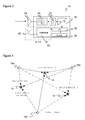
- Figure 1 shows an embodiment of a system 10 according to the invention installed in an indoor environment 12, for example a hall or a warehouse. While the system 10 in principle will also work outside, it is described in an indoor application because of competing satellite-based systems available in outdoor applications.
- the system 10 comprises a receiving device 14 which is either moving by itself or attached to a moving object 16 like a vehicle, in particular an AGV (Automated Guided Vehicle).
- the system 10 further comprises a plurality of transmitters 18a-d, sometimes also referred to as beacons, which are randomly placed within the indoor environment 12, for example at a ceiling.
- a number of three transmitters 18a-c should preferably be in line of sight at any position accessible by the receiving device 14. To that end, a larger number of transmitters 18a-d may be installed, with the illustrated number of four transmitters 18a-d being merely one example.
- the task of system 10 is to localize receiving device 14 based on transmission and reception of signals.
- These signals may be ultrasonic signals, which implies that receiving device 14 is capable of receiving ultrasound and transmitters 18a-d generate ultrasound.
- the system 10 can also use electromagnetic signals instead of ultrasound.
- transmitters 18a-d nor receiving device 14 are connected to a communication system for synchronization. Consequently, transmitters 18a-d are synchronized both among one another and with receiving device 14. This does not expressly exclude means of communication and not even synchronization for any conceivable alternative embodiment, but the receiving device 14 in any case does not rely on nor require synchronization, but is able to locate its position based on the timing of received signals alone.
- Fig. 2 shows a block diagram of one of the transmitters 18.
- the transmitter 18 comprises a control 20, a clock 22, signal processing means 24, and a loudspeaker or ultrasound generating means 26.
- the signal to be emitted is generated by the control 20, amplified and possibly filtered by signal processing means 24, and emitted by the ultrasound generating means 26.
- the signal is modulated by a transmission pattern encoding the identity of transmitter 18. This can be done with any known modulation scheme, for example in a pulse sequence, a burst, or a chirp.
- the known method of chirp spread spectrum represents bits using a rising and falling frequency sweep. Chirp spread spectrum is robust against multipath effects, where several echoes of the same signal may reach receiving device 14 in phase and out of phase. By using a chirp spread spectrum, the amplified and attenuated signals are in balance because all energy shares are considered.
- Each transmitter 18a-d emits its individually modulated signal periodically and independent of the other transmitters 18a-d.
- Transmitters 18a-d can thus be simple in construction and do not need communication means or control.
- Periodic transmission implies that preferably short signals are emitted at a specific rate. The period may or may not vary from transmitter 18a-d to transmitter 18a-d. Since transmitters 18a-d are unsynchronized, different periods can be achieved by each transmitter 18a-d using an individual or random period. The starting points of period transmission are arbitrary due to the unsynchronized activity. The mutual time offsets of transmitters are therefore unknown even if transmitter positions and the time intervals defining the activity periods are determined. Sender offsets would anyway need to be continuously observed because of drifts of the clocks 22. Receiving device 14 has no knowledge of transmission points in time or the periods between two transmissions.
- each of the transmitters 18a-d is active without consideration of the other transmitters' 18a-d activity, the risk of signal collisions is high. However, loss of a few signals is acceptable, and it is assumed that collisions can be detected and the signals be discarded.
- FIG. 3 shows a block diagram of receiving device 14, which comprises an analog reception path with a microphone or ultrasonic receiving means 28, filtering means 30, amplifying means 32, an A/D converter 34, a control 36, and a clock 38.
- the signals after having passed the analog reception path, are digitally analyzed by control 36.
- the evaluation detects both the identity of the transmitter 18a-d and a reception point in time from a signal.
- control 36 can detect the presence of a specific transmitter 18a-d and determine the exact reception point in time when its signal reaches receiving device 14.
- One method of identifying a transmitter is cross-correlation of received signal and each of a number of transmission patterns that could have been used to identify the transmitters 18a-d. The correlation peaks both indicate the reception points in time and reveal the unique identifier of the transmitter 18a-d where the signal originated.
- control 36 has a memory where the transmitter positions are stored. These have been parameterized or determined in a calibration process.
- the reception points in time, also referred to as time stamps, and the transmitter positions are used to calculate the position of the receiving device 14. Methods for both an automatic self-calibration to determine the transmitter positions in a preparatory step and to locate the receiving device 14 without synchronization will be described in later sections of this description.
- the memory may also be used to store a software containing an implementation of the functions of control 38.
- the receiving device 14 may optionally comprise an interface 40 for data communication, which preferably operates according to a wireless standard, as symbolized by antenna 44.
- This interface 40 is not necessary for the localization, but is used to transmit device information to a base station or to receive parameters or control commands from the base station.
- the problem of localizing receiving unit 14 is comparably simple if it temporarily stops to collect measurements from transmitters 18a-d within reach. This is illustrated in Figure 4 .
- Figure 5 shows a more natural situation where the receiving device 14 continually moves along a trajectory.
- the measurements take place at different positions, increasing the number of variables and generating an under-determined equation system.
- the equations are no longer hyperbolic.
- This problem will later on be tackled by recursive state estimation algorithms with the assumption of a continuous trajectory.
- using the Extended or the Unscented Kalman filter is advisable.
- a particle filter is used which is robust against non-Gaussian observations and which can represent a non-Gaussian state estimation, yet at the price of higher computational cost.
- recursive filters initially require some iterations to generate useful results, so position data is available only after some time, even if the mutual time offsets of the transmitters were known.
- An alternative approach to solving the continuous movement problem of Figure 5 is to make simplifying assumptions. As a first rough approximation, the movement of the receiving device 14 is ignored. The velocity of receiving device 14 is probably small, so the positioning error by ignoring movement during the short time interval needed to capture the signals can be expected to also be small. A somewhat more advanced approach estimates a velocity of the receiving device 14 from previous localization and extrapolates a constant movement. Then, the positions of the receiving device 14 are reduced to a linear function, making the problem no more complex than in the stationary case.
- M t ⁇ R 2 denotes the position of the receiver at time t.
- a number of m stationary transmitters 18a-d, subsequently referred to as senders, is placed randomly at unknown positions S i , (1 ⁇ i ⁇ m ) . Every sender emits discrete signals at regular points in time with a period defined by a fixed interval I i . The interval may differ from sender to sender.
- the identifiers and positions of the transmitters 18a-d need to be known in receiving device 14. Although it is conceivable to manually parameterize receiving device 14 accordingly or to perform a conventional position measurement, it is preferred to save this information in receiving device 14 after an automatic calibration method.
- a set of possible transmission patterns identifying a transmitter 18a-d can be known per default and can moreover be reduced to those transmission patterns actually received during calibration.
- Calculation of the sender positions is a one-time task. Once the sender positions are known, the position information is downloaded by the receivers, so they may localize themselves with respect to the senders.
- the receiver has to be brought close to every sender, such that the receiver and every pair of senders are aligned and the maximum possible time difference is produced.
- the receiver moves on a trajectory beyond the vicinity of the senders. If the receiver moves slowly in comparison to the signal velocity, an approximation of the time differences at certain points can be measured.
- T si describes the timestamp of the signal which has been received at measurement point s
- T 0 i describes the timestamp for the first point, respectively.
- the precision of the Ellipsoid TDoA method depends on the far-field assumption of the receiver, therefore if the receiver is too close to the senders, an error is induced into the distance calculation, leading to an under-estimation of the sender distances.
- the precision of the MinMax procedure depends on the availability of measurements on the "long edges" of the senders, therefore an alignment of each pair of two senders and the receiver on a line. As only a single maximum time difference is evaluated, the MinMax procedure is also prone to measurement errors. Such errors may be compensated by error mitigation algorithms such as RANSAC (Random Sample Consensus).
- Bayesian filtering scheme has been successfully applied to TDoA problems previously, yet for estimation of a moving sender (cf. J. Wendeberg et al. "Robust Tracking of a Mobile Beacon Using Time Differences of Arrival with Simultaneous Calibration of Receiver Positions", Proceedings of 2012 International Conference on Indoor Positioning and Indoor Navigation (IPIN); 2012 ).
- the Bayesian filtering scheme is a probabilistic approach to recursive state estimation based on the Markov assumption, i.e. the assumption that the current state depends only on the previous state, not on the previous trajectory.
- the posterior distribution, or belief, can be described by the recursive update equation p x t
- z 1 : t , u 1 : t ⁇ t ⁇ p z t ⁇ x t ⁇ p ⁇ x t
- u 1: t ,x 1: t ) dx t 1.
- x t ) are specified by the motion model and sensor model, respectively.
- the particle filter and the unscented Kalman filter which are implementations of the Bayesian filtering model.
- the particle filter uses a set of particles to represent a state hypothesis, approximating the current belief.
- the unscented Kalman filter uses the knowledge of the noise factors involved in the system to estimate a Gaussian probability function of the state.
- the non-linear functions, which are characteristical for TDoA, are linearized in the unscented transform.
- the sending time of one sender must be estimated, as in TDoA only relative distances are measured.
- the algorithms use a motion model to propagate the state hypothesis in the current time step based on the previous belief, as well as a sensor model which determines the likelihood of observed measurements.
- the design of the motion model is crucial for the proper estimation of the state transition, and therefore for efficiency and accuracy of the localization.
- we use the same motion model which is based on the model in the article "Robust Tracking of a Mobile Beacon Using Time Differences of Arrival with Simultaneous Calibration of Receiver Positions", loc. cit.
- the model we assume that no control over the movement of the receiver is given, hence the control command represents just the time which has passed since the last computation. For the movement, and therefore the next estimated position of the receiver, we use a constant velocity model.
- the particle filter also known as Monte Carlo localization, recursively approximates the current system state based on the previous system state.
- a set of particles of size N represents the current belief p ( x t
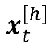
- Each particle x t h ⁇ w t h , (1 ⁇ h ⁇ N) represents a hypothesis of the system state at time t and consists of a system state x t h and the so-called importance weight w t h .
- the particle filter estimates the values in the current step.
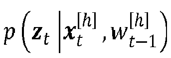
- the sensor model computes the probability p ⁇ z t
- the recursive belief update of the particle filter is done according to the following three steps:
- the particles represent the estimated state as described in Eq. (16).
- the probability of the current measurement is the product of all measurements: p z t
- the likelihood of a measurement is calculated by p z j
- x t N z j ⁇ d tj ⁇ ⁇ sensor 2 , where ⁇ sensor 2 is a variance estimation of the sensor noise, which is assumed to be Gaussian distributed.
- the unscented Kalman filter (UKF), which was proposed by Julier and Uhlman in "New Extension of the Kalman Filter to Nonlinear Systems” in AeroSense'97, International Society for Optics and Photonics, 1997, pp. 401-422., 2004 , is a recursive state estimator based on the unscented transform, an approach to linearization of non-linear models.
- 2 L + 1 "sigma points" are generated deterministically with the known covariance matrix of the involved variables and the tuning parameters of the filter.
- the UKF is cheaper in computation than the particle filter, which requires evaluation of a large number of particles, or the extended Kalman filter, which requires calculation of the Jacobian matrix.
- a simulation compares the two algorithms and the precision of their localization in identical scenarios.
- both algorithms were given measurements with a Gaussian distributed error with standard deviation of 0.3 ms which was added to the reception times.
- the initialization for the particle filter and the UKF was chosen with more precision at a uniform error of 1 m added to the true receiver position.
- Figure 6 shows a comparison of real trajectory, trajectory estimate by particle filtering, and trajectory estimated by Kalman filtering. Both algorithms are well capable to follow the true trajectory of the receiver, based on the incoming signals, even though these are subject to Gaussian measurement errors, with a moderate advantage of the particle filter. A drag towards the outside of a curve is caused by inertia of the constant velocity model until the measurements suggest the changing direction.
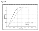
- Figure 7 shows the cumulative distribution of errors of the particle filter and the unscented Kalman filter according to the received signals. It shows that the estimation of the particle filter has a moderately smaller error. However, the error of the unscented Kalman Filter is not that much larger, in particular in view of significantly reduced computational costs.
Landscapes
- Physics & Mathematics (AREA)
- Engineering & Computer Science (AREA)
- General Physics & Mathematics (AREA)
- Radar, Positioning & Navigation (AREA)
- Remote Sensing (AREA)
- Probability & Statistics with Applications (AREA)
- Position Fixing By Use Of Radio Waves (AREA)
Abstract
Description
- The invention relates to a self-locating mobile receiving device and a method for localizing a mobile receiving device according to the preamble of
claim 1 and 15, respectively. - The rise of mobile technology in every-day life and the employment of mobile autonomous agents in industrial logistics has led to an increasing demand for location based services in indoor scenarios. In industrial logistics applications, for example, a large number of autonomous agents transport goods based on dynamic assignments. Forwarding goods from a material source to a drain requires absolute localization in the working environment. Navigation satellite based solutions lack connectivity in these environments, so alternatives must be considered.
- Known indoor localization systems include a set of electromagnetic or ultrasound transmitters to replace the satellite signals. The receiver to be located may adopt various strategies to evaluate these signals including RSSI (Received Signal Strength Indicator) and TOF (Time of Flight). Instead of determining the absolute time of flight from a transmitter to a receiver, time difference of arrival (TDoA) or frequency distance of arrival (FDoA) systems evaluate the differences of signals travelling on more than one signal path.
- However, the RSSI is often distorted by objects in the direct signal path and its vicinity and also by environmental interference like air humidity. Systems using time of flight, on the other hand, strongly depend on precise synchronization. The actual localization errors introduced by synchronization delays depend on the nature of the signals and their propagation speed. Thus, errors are more significant in case of electromagnetic waves than in case of ultrasound signals. In any case, synchronization needs means of communication. The cabling for wired communication increases installation costs, while wireless communication is limited in distance and may be unreliable or even not be tolerated in industrial environments.
- Common indoor localization systems also require an initial calibration step to gain knowledge of transmitter positions. This adds to the installation costs and requires skilled personnel.
- More background information regarding existing indoor localization systems can be found in J. Wendeberg et al. "Self-Localization based on Ambient Signals", Theoretical Computer Science, 453:98-109, 2012; T. Janson et al. "Self-Localization Application for iPhone using only Ambient Sound Signals", Proceedings of the 2010 International Conference on Indoor Positioning and Indoor Navigation (IPIN), pages 259-268, Nov. 2010; J. Wendeberg et al. "Calibration-Free TDOA Self-Localization", Journal of Location Based Services, 2013; and F. Höflinger et al. "Acoustic Self-calibrating System for Indoor Smartphone Tracking (ASSIST)"; Proceedings of the 2012 International Conference on Indoor Positioning and Indoor Navigation (IPIN), 2012.
- It is therefore an object of the invention to provide improved indoor localization.
- This object is satisfied by a self-locating mobile receiving device and a method for localizing a mobile receiving device according to
claim 1 and 15, respectively. The receiving device evaluates signals received from a plurality of transmitters, in particular stationary transmitters. Although any signal may be used, including electromagnetic signals like radio or light, ultrasound signals are particularly useful in indoor applications. Of course, both transmitters and receiving device are of the appropriate type. Preferably, at least three transmitters are within reach at any time, so that more transmitters can be installed in larger areas or where intermitting objects in the line of sight are expected. For each received signal, the evaluation identifies the respective transmitter and determines a reception point in time, resulting in a number of time stamps after repeated measurements. In case of a frequency based method, the reception point in time may be a phase. Based on transmitter identity, associated reception point in time, and transmitter positions, the mobile receiving device is localized. - The invention starts from the basic idea that localization does not require synchronization of the transmitters among each other and/or with the receiving device. No information about the transmission points in time when a transmitter emits a signal has to be communicated. Instead, information about transmission points in time or related variables, like mutual offsets of transmission points in time, is estimated using the reception points in time.
- The fact that the estimation does not require synchronization does not necessarily exclude synchronization. For example, components may initially be synchronized, with the estimation during operation compensating drifts.
- The invention has the advantage that the costs and installation effort for localization is reduced to a minimum. At the same time, high accuracy and robustness of the localization of an arbitrary number of receiving devices is possible. The receiving device can be passive and therefore does not need any means of generating a signal to contact the transmitters. The transmitters do not need any wired or wireless connection.
- The evaluation unit is preferably configured to identify a transmitter by correlation with a known transmission pattern. The transmission pattern encodes the identity. By correlation with known transmission patterns which might be used by transmitters, the receiving device identifies the transmitter that sent a received signal. The correlation peak can also determine the reception point in time.
- The evaluation unit is preferably configured to estimate the position of the receiving device with a time difference of arrival (TDoA) and/or a frequency difference (FDoA) of arrival method. Both methods may be implemented for a complementary evaluation, for example enhancing the TDoA localization by another FDoA localization.
- The evaluation unit is preferably configured to estimate the position of the receiving device with a recursive filter, in particular a particle filter or a Kalman filter. In case of a moving device, closed calculation of the device's position is not possible because there are more variables than constraints. By using recursive filters, the history is also considered. Plausibility assumptions, like a maximum speed of the receiving device or a continuous movement, may increase filter performance.
- The recursive filter preferably also estimates transmission points in time and/or mutual offsets of transmission points in time. There is thus one filter for estimating both the missing synchronization information and the position of the receiving device.
- The evaluation unit is preferably configured for a self-calibration determining at least one of identities of transmitters within reach, transmitter positions, and a time interval between transmissions of a transmitter. The calibration procedure thus does not require professional staff and is extremely easy.
- The evaluation unit is preferably configured to evaluate an intensity of a received signal in order to enhance the estimation of the position of the receiving device. The intensity could for example be used for a second, independent localization, which is subsequently used for a comparison or a weighted averaging. Intensity can also be used for a plausibility test to detect multipath propagation.
- The receiving device preferably comprises an inertial measurement unit for measuring an acceleration, wherein the evaluation unit is configured to include the acceleration in the estimation of the position of the receiving device. The acceleration may be linear and/or rotational. Acceleration information may be used to internally track the position of the receiving device. Another device to that end is an odometer. During usual operation, the internal tracking information may be used to increase accuracy of localization. In case that an insufficient number signals is received from the transmitters due to range limitations or obstacles, the internal tracking can temporarily take over.
- The receiving device preferably comprises an interface to transfer device information including the position of the receiving device to a base station. The interface may also be used to receive commands or parameters from the base station. Any known technology can be used for the interface, including wireless standards like GSM, UMTS, LTE, or WiFI, or wired standards like Ethernet, USB, Firewire, or Homeplug. The interface is not required for localization, but used for data management, higher-order evaluation or control, like displaying the positions of all receivers and task or movement planning.
- In another preferred embodiment, a system comprises at least one mobile receiving device according to the invention and a plurality of stationary transmitters, each of the transmitters transmitting signals encoding the transmitter's identity. As the receiving devices are preferably passive, there is no restriction on the number of receiving devices using the transmitters for self-localization. The transmitters can be stationary and arbitrarily placed, but preferably a number of at least three transmitters cover any possible position of a receiving device.
- The transmitters preferably transmit their signals independently. The transmitters are therefore unsynchronized. This makes both the transmitters as a device and their installation extremely simple. They do not have a connection with or any other means of receiving information from each other. They do not know or care for the other transmitter's activity.
- Signalling periods and/or transmission points in time of any one of the transmitters is preferably neither communicated to the other transmitters nor to the mobile receiving devices. No information regarding timing of the transmitters is exchanged. Only by its specific estimator, but independent of synchronization, will the receiving device at least implicitly reconstruct the timing when estimating its position.
- Each of the transmitters preferably transmits its signal periodically. In other words, the transmitter emits a signal at regular or equidistant time intervals. The transmitters may all use the same period or add an individual or random element to decrease the risk for signal collisions. In any case, this risk is low, because there are mutual time offsets due to the transmitters being unsynchronized. Additional time offsets are introduced by the variable distance of transmitter and receiving device. In case of signal collisions, the correlator of the receiving device may still be able to separate the signals. Otherwise, the colliding signals may simply be discarded, and a subsequent measurement be used for localization.
- The signal transmitted by each of the transmitters is preferably an individual burst or an individual chirp. This enables the receiving device to reliably identify the transmitter. Moreover, burst and chirps can be short. This reduces the risk of signal collision, and a low duty cycle is advantageous for its energy-efficiency. For example, a signal of 1 ms could be followed by a break of 300 ms. Generally, the pulse duty factor can range between 1:1 and 1:1000 or less, or more specifically between 1:50 and 1:100.
- The transmitters preferably comprise an independent power supply, in particular an energy harvesting device. This makes transmitters completely independent. In contrast to batteries which in principle can be used, energy-harvesting devices such as indoor photo cells don not need maintenance or replacement.
- The method in accordance with the invention can be further developed in a similar manner and shows similar advantages. Such advantageous features are described in an exemplary, but not exclusive manner in the subordinate claims dependent on the independent claims.
- The invention will be explained in more detail in the following also with respect to further features and advantages by way of example with reference to embodiments and to the enclosed drawing. The Figures of the drawing show in:
- Fig. 1
- a three-dimensional overview of a system comprising a plurality of transmitters and a receiving device to be localized;
- Fig. 2
- a block diagram of a transmitter;
- Fig. 3
- a block diagram of a receiving device;
- Fig. 4
- a schematic plan view illustrating measurements for locating a stationary receiving device;
- Fig. 5
- a schematic plan view illustrating measurements for locating a mobile receiving device;
- Fig. 6
- a comparison of a receiving device's trajectory and two estimations of the trajectory based on a particle filter and an unscented Kalman filter, respectively; and
- Fig. 7
- a diagram showing the cumulative distribution function of the receiver error for the two estimations of
Figure 6 . -
Figure 1 shows an embodiment of asystem 10 according to the invention installed in anindoor environment 12, for example a hall or a warehouse. While thesystem 10 in principle will also work outside, it is described in an indoor application because of competing satellite-based systems available in outdoor applications. - The
system 10 comprises a receivingdevice 14 which is either moving by itself or attached to a moving object 16 like a vehicle, in particular an AGV (Automated Guided Vehicle). Thesystem 10 further comprises a plurality oftransmitters 18a-d, sometimes also referred to as beacons, which are randomly placed within theindoor environment 12, for example at a ceiling. A number of threetransmitters 18a-c should preferably be in line of sight at any position accessible by the receivingdevice 14. To that end, a larger number oftransmitters 18a-d may be installed, with the illustrated number of fourtransmitters 18a-d being merely one example. - The task of
system 10 is to localize receivingdevice 14 based on transmission and reception of signals. These signals may be ultrasonic signals, which implies that receivingdevice 14 is capable of receiving ultrasound andtransmitters 18a-d generate ultrasound. However, thesystem 10 can also use electromagnetic signals instead of ultrasound. - In the
system 10, neithertransmitters 18a-d nor receivingdevice 14 are connected to a communication system for synchronization. Consequently,transmitters 18a-d are synchronized both among one another and with receivingdevice 14. This does not expressly exclude means of communication and not even synchronization for any conceivable alternative embodiment, but the receivingdevice 14 in any case does not rely on nor require synchronization, but is able to locate its position based on the timing of received signals alone. -
Fig. 2 shows a block diagram of one of thetransmitters 18. Thetransmitter 18 comprises acontrol 20, aclock 22, signal processing means 24, and a loudspeaker or ultrasound generating means 26. The signal to be emitted is generated by thecontrol 20, amplified and possibly filtered by signal processing means 24, and emitted by the ultrasound generating means 26. - The signal is modulated by a transmission pattern encoding the identity of
transmitter 18. This can be done with any known modulation scheme, for example in a pulse sequence, a burst, or a chirp. The known method of chirp spread spectrum represents bits using a rising and falling frequency sweep. Chirp spread spectrum is robust against multipath effects, where several echoes of the same signal may reach receivingdevice 14 in phase and out of phase. By using a chirp spread spectrum, the amplified and attenuated signals are in balance because all energy shares are considered. - Each
transmitter 18a-d emits its individually modulated signal periodically and independent of theother transmitters 18a-d.Transmitters 18a-d can thus be simple in construction and do not need communication means or control. Periodic transmission implies that preferably short signals are emitted at a specific rate. The period may or may not vary fromtransmitter 18a-d totransmitter 18a-d. Sincetransmitters 18a-d are unsynchronized, different periods can be achieved by eachtransmitter 18a-d using an individual or random period. The starting points of period transmission are arbitrary due to the unsynchronized activity. The mutual time offsets of transmitters are therefore unknown even if transmitter positions and the time intervals defining the activity periods are determined. Sender offsets would anyway need to be continuously observed because of drifts of theclocks 22. Receivingdevice 14 has no knowledge of transmission points in time or the periods between two transmissions. - As each of the
transmitters 18a-d is active without consideration of the other transmitters' 18a-d activity, the risk of signal collisions is high. However, loss of a few signals is acceptable, and it is assumed that collisions can be detected and the signals be discarded. -
Figure 3 shows a block diagram of receivingdevice 14, which comprises an analog reception path with a microphone or ultrasonic receiving means 28, filtering means 30, amplifying means 32, an A/D converter 34, acontrol 36, and a clock 38. The signals, after having passed the analog reception path, are digitally analyzed bycontrol 36. The evaluation detects both the identity of thetransmitter 18a-d and a reception point in time from a signal. In other words, control 36 can detect the presence of aspecific transmitter 18a-d and determine the exact reception point in time when its signal reaches receivingdevice 14. One method of identifying a transmitter is cross-correlation of received signal and each of a number of transmission patterns that could have been used to identify thetransmitters 18a-d. The correlation peaks both indicate the reception points in time and reveal the unique identifier of thetransmitter 18a-d where the signal originated. - In addition to that measurement information,
control 36 has a memory where the transmitter positions are stored. These have been parameterized or determined in a calibration process. The reception points in time, also referred to as time stamps, and the transmitter positions are used to calculate the position of the receivingdevice 14. Methods for both an automatic self-calibration to determine the transmitter positions in a preparatory step and to locate the receivingdevice 14 without synchronization will be described in later sections of this description. The memory may also be used to store a software containing an implementation of the functions of control 38. - The receiving
device 14 may optionally comprise aninterface 40 for data communication, which preferably operates according to a wireless standard, as symbolized by antenna 44. Thisinterface 40 is not necessary for the localization, but is used to transmit device information to a base station or to receive parameters or control commands from the base station. - The problem of localizing receiving
unit 14 is comparably simple if it temporarily stops to collect measurements fromtransmitters 18a-d within reach. This is illustrated inFigure 4 . The receivingdevice 14, marked as "stationary receiver", stops at three examplary measurement positions to gather signals from thetransmitters 18a-d marked as "satellites". - As these measurements occur from the same position, using the time differences of arrival results in hyperbolic equations which can be solved by conventional algorithms like linear estimators or by few iterations of the Gauss-Newton algorithm. Yet even in the stationary situation, transmitter positions and mutual time offsets of the
transmitters 18a-d have to be known which complicates matters. -
Figure 5 shows a more natural situation where the receivingdevice 14 continually moves along a trajectory. The measurements take place at different positions, increasing the number of variables and generating an under-determined equation system. The equations are no longer hyperbolic. This problem will later on be tackled by recursive state estimation algorithms with the assumption of a continuous trajectory. As the hyperbolic equations lead to a non-linear observation model, using the Extended or the Unscented Kalman filter is advisable. Alternatively, a particle filter is used which is robust against non-Gaussian observations and which can represent a non-Gaussian state estimation, yet at the price of higher computational cost. In contrast to optimization or closed-form calculation, recursive filters initially require some iterations to generate useful results, so position data is available only after some time, even if the mutual time offsets of the transmitters were known. - An alternative approach to solving the continuous movement problem of
Figure 5 is to make simplifying assumptions. As a first rough approximation, the movement of the receivingdevice 14 is ignored. The velocity of receivingdevice 14 is probably small, so the positioning error by ignoring movement during the short time interval needed to capture the signals can be expected to also be small. A somewhat more advanced approach estimates a velocity of the receivingdevice 14 from previous localization and extrapolates a constant movement. Then, the positions of the receivingdevice 14 are reduced to a linear function, making the problem no more complex than in the stationary case. - Having described the localization problem and the inventive solution in more general terms, the remainder of the description will introduce detailed mathematical embodiments. Although the equations and algorithms are a preferred implementation of the invention, there are other possibilities, with the scope of the invention being defined by the claims.
- We consider the localization problem of receiving
device 14, subsequently referred to as the receiver, moving on an unknown trajectory in two-dimensional Euclidean space. An extension to three dimensions is possible, and the implementation straightforward by merely increasing the state vector size.
stationary transmitters 18a-d, subsequently referred to as senders, is placed randomly at unknown positions Si , (1 ≤ i ≤ m). Every sender emits discrete signals at regular points in time with a period defined by a fixed interval Ii . The interval may differ from sender to sender. - Then, the transmission point in time or sending time of the ki -th signal at sender position Si is described by

- Furthermore, we assume that a ki -th signal of sender Si propagates in a straight line from the sender to the receiver and is received at reception point in time

- The computation of the length of the intervals of the different senders by the receiver is straightforward by receiving two or more successive signals k 1 , k 2 , k 1 ≠ k 2, emitted by the same sender Si while it is temporarily stationary. Then the interval for sender Si is

- The transmission points in time or sending timestamps, as well as the positions of the senders and the current receiver position, remain unknown up to now, and only the signal speed c and the time when a signal has been received, T, are known. To successfully compute the position of the receiver, more effort is needed.
- In addition to this, the senders are assumed to be unsynchronized, i.e. they send their signals after different intervals Si and have a different initial transmission point in time or send time t 0i . Consequently, there is an unknown time offset δij between the senders, which describes the send time difference between senders Si and Sj. It is calculated by

- If all

i i and Mkj j :

- In this equation, m is the number of senders, so m - 1 offsets are required. Assuming the intervals Ii and Ij to be known, there exist 2nm + (m - 1) unknown variables after n received signals from each sender and therefore unknown receiver positions (cf.
Figure 5 ). It is apparent that this equation cannot be solved in closed form and without further knowledge of or assumptions on the scenario. - For the system to be operable, the identifiers and positions of the
transmitters 18a-d need to be known in receivingdevice 14. Although it is conceivable to manually parameterize receivingdevice 14 accordingly or to perform a conventional position measurement, it is preferred to save this information in receivingdevice 14 after an automatic calibration method. A set of possible transmission patterns identifying atransmitter 18a-d can be known per default and can moreover be reduced to those transmission patterns actually received during calibration. - It is more involved to calculate the sender positions. Calculation should solely be based on evaluation of the time differences observed by the receivers. This eliminates the need to manually measure senders, enabling the user of the localization system to install them at arbitrary places. Thus, sort of a "plug-and-play" localization system is provided.
- Calculation of the sender positions is a one-time task. Once the sender positions are known, the position information is downloaded by the receivers, so they may localize themselves with respect to the senders.
- For localization of the senders only by measurements of unknown receivers, an adaption of two approaches may be applied, the Ellipsoid TDoA method (see "Self-Localization based on Ambient Signals", loc. cit.) and a statistical approach that estimates the distance between senders based on the distribution and minima/maxima of the observed reception times (cf. "Self-Localization Application for iPhone using only Ambient Sound Signals", loc. cit.).
- For the statistical algorithms, the receiver has to be brought close to every sender, such that the receiver and every pair of senders are aligned and the maximum possible time difference is produced. Alternatively, the receiver moves on a trajectory beyond the vicinity of the senders. If the receiver moves slowly in comparison to the signal velocity, an approximation of the time differences at certain points can be measured.
- To compute the distances between sender pairs, the Ellipsoid TDoA method uses linear regression to calculate an approximation of the distances of three senders S i, S j, and S k based on the ellipsoid equation


- Using the "MinMax" procedure, therefore evaluating the minimum and maximum occurring TDoA, the time difference of every measurement point and the first point is calculated by

- Tsi describes the timestamp of the signal which has been received at measurement point s, and T 0i describes the timestamp for the first point, respectively. Once the time shift has been determined for all stops and all senders the difference of these shifts is be calculated for each stop by

- This calculation results in sets of time differences for each sender pair, Kij = {Δt 0ij ,...,Δtsij }. The distance between two of those senders is an approximation of the maximum and minimum values of the respective set for senders S i and S j:

- After one of the distance approximation procedures has been applied, where the choice of the algorithm depends on the flexibility of receiver movements and the availability of calibration measurements, the distances are known, and the senders can be placed in a coordinate system by solving a problem of multi-dimensional scaling (cf. J. Kruskal et al., "Multidimensional Scaling", Sage Publications, 1978).
- The precision of the Ellipsoid TDoA method depends on the far-field assumption of the receiver, therefore if the receiver is too close to the senders, an error is induced into the distance calculation, leading to an under-estimation of the sender distances. The precision of the MinMax procedure depends on the availability of measurements on the "long edges" of the senders, therefore an alignment of each pair of two senders and the receiver on a line. As only a single maximum time difference is evaluated, the MinMax procedure is also prone to measurement errors. Such errors may be compensated by error mitigation algorithms such as RANSAC (Random Sample Consensus).
- As discussed above, the equation system in (5) for the situation of
Figure 5 is under-determined and cannot be calculated directly, as only one equation is available for every receiver position. Instead, we consider the positioning problem of a continuously moving receiver as a recursive state estimation problem. We will describe two novel approaches based on probabilistic state estimation to enable robust localization of the mobile receiver, once the senders have been located, only by the reception times of the signals from the senders. - A Bayesian filtering scheme has been successfully applied to TDoA problems previously, yet for estimation of a moving sender (cf. J. Wendeberg et al. "Robust Tracking of a Mobile Beacon Using Time Differences of Arrival with Simultaneous Calibration of Receiver Positions", Proceedings of 2012 International Conference on Indoor Positioning and Indoor Navigation (IPIN); 2012). The Bayesian filtering scheme is a probabilistic approach to recursive state estimation based on the Markov assumption, i.e. the assumption that the current state depends only on the previous state, not on the previous trajectory.
- We present an approach based on a stochastic Monte-Carlo simulation, also known as particle filter, which is robust to motion and measurement uncertainties, and therefore well suited for TDoA localization. Furthermore, we present an approach based on the unscented Kalman filter, which is an efficient algorithm that is robust even in a non-linear problem setting. It turns out that using a particle filter yields a robust solution, yet at high computational cost, and that the unscented Kalman filter (UKF) is still reliable and at the same time computationally efficient.
- In a recursive Bayesian filter, the probability p(xt |z 1: t,u 1:t ) of state xt at time t is assumed to depend on the obtained sensor data z 1:t and control commands u 1:t . The posterior distribution, or belief, can be described by the recursive update equation

- For both algorithms we estimate the same state, consisting of the position vector M t of the receiver at time t, as well as the movement velocity of the receiver V t .
- Since the senders are unsynchronized, the time offsets δij need to be estimated as well. In order to calculate the offset between S i and S j with respect to the sending times t 0 i, t 0j we use the equation
 is uniformly distributed noise in a time range of t dist. As the offsets are transitive, we settle to estimate m - 1 offsets. Without loss of generality we estimate only the offset relative to sender j = 1 and define δi = δ1i , where δ 1 = 0.
- Also the sending time of one sender must be estimated, as in TDoA only relative distances are measured. To propagate the estimated sending time of the latest received signal of sender i, we use the last estimated sending time, the interval length, and a uniform distributed noise term as

- We add the uniformly distributed noiseto increase the variance of the estimated offsets. As the send times tk

i i are all relative, we estimate only t k1 1. Altogether, the state vector is
- The algorithms use a motion model to propagate the state hypothesis in the current time step based on the previous belief, as well as a sensor model which determines the likelihood of observed measurements. The design of the motion model is crucial for the proper estimation of the state transition, and therefore for efficiency and accuracy of the localization. For both algorithms we use the same motion model, which is based on the model in the article "Robust Tracking of a Mobile Beacon Using Time Differences of Arrival with Simultaneous Calibration of Receiver Positions", loc. cit. In the model, we assume that no control over the movement of the receiver is given, hence the control command represents just the time which has passed since the last computation. For the movement, and therefore the next estimated position of the receiver, we use a constant velocity model. This model assumes that the receiver moves with constant velocity, while changes in the velocity are undetermined, which is modeled by Gaussian noise with a covariance matrix ∑ V . In this model, the position and velocity of the receiver are updated according to the Euler integration scheme by

i i-Tkj j > 0 is the time between the current signal from sender i and the previous signal from sender j. - The particle filter, also known as Monte Carlo localization, recursively approximates the current system state based on the previous system state. For an explanation of the particle filter, see also "Robust Tracking of a Mobile Beacon Using Time Differences of Arrival with Simultaneous Calibration of Receiver Positions", loc. cit. A set of particles of size N represents the current belief p(xt |z 1:t , u 1:t ). Each particle




- The recursive belief update of the particle filter is done according to the following three steps:
- 1. In the prediction step, the hypothetical state of a particle

- 2. In the correction step, a current measurement z t is used to update the weight,

- 3. In the resampling step, a set of N particles is drawn, replacing the weighted state hypothesis, i.e. the probability of drawing a particle is proportional to its weight.
- In our proposed implementation, resampling is executed if the effective number of particles N eff, is smaller than the number of


- The particles represent the estimated state as described in Eq. (16). The sensor model uses the measurement zj = Tk
j j , which is the timestamp of last received signal originating from sender j, to compute the probability that the observed measurement matches the current belief. Here, we assume that the different measurements are independent, given the current state xt of the system. Therefore, the probability of the current measurement, given the system state xt , is the product of all measurements:
- To evaluate the estimated values, each measurement zj is taken into account. Based on the known sender positions Sj and the estimated values M t, t k
1 1 , and δj , a hypothesis of the observation is calculated by
- Using this hypothesis dtj , the likelihood of a measurement is calculated by


- The unscented Kalman filter (UKF), which was proposed by Julier and Uhlman in "New Extension of the Kalman Filter to Nonlinear Systems" in AeroSense'97, International Society for Optics and Photonics, 1997, pp. 401-422., 2004, is a recursive state estimator based on the unscented transform, an approach to linearization of non-linear models. For a random variable with dimension L, 2L + 1 "sigma points" are generated deterministically with the known covariance matrix of the involved variables and the tuning parameters of the filter. As the evaluation of the models is calculated only for the 2L + 1 sigma points, the UKF is cheaper in computation than the particle filter, which requires evaluation of a large number of particles, or the extended Kalman filter, which requires calculation of the Jacobian matrix.
- 1) Generating sigma points: First, an extended mean vector and covariance matrix are generated:


The augmented mean and variance are used to generate a set of 2L sigma points, where L is the dimension of the augmented mean vector:


- 2) Prediction: The sigma points matrix now has a dimension of L × (2L + 1). This matrix has rows in the space of the previous state, the measurement noise and the process noise:

Each row has 2L + 1 sigma points. The sigma points of the previous state and the process noise are passed to a function g, which is the motion model defined in Eqns. (14) and (17), to predict the new state:
After that, the Gaussian statistics of the new points are computed by

The parameter β is a tuning parameter of the filter which has to be set depending on the a priori knowledge of the state probability distribution. The observations at the sigma points are calculated in the sensor model by
In our case, the sensor model follows this equation for every sigma point:
- 3. Correction: In the final step, the Gaussian statistics of the observations at the sigma points and the predicted state are calculated to correct the measurement.

In this step, the cross-covariance between the predicted state and the predicted measurement is also calculated:
Finally, the mean and the covariance of the state are updated by

- A simulation compares the two algorithms and the precision of their localization in identical scenarios. We used a fixed trajectory for both algorithms, traversing the entire experimental field of 15 m x 15 m, with a fixed number of three well-placed receivers. For this comparison both algorithms were given measurements with a Gaussian distributed error with standard deviation of 0.3 ms which was added to the reception times. The initialization for the particle filter and the UKF was chosen with more precision at a uniform error of 1 m added to the true receiver position.
-
Figure 6 shows a comparison of real trajectory, trajectory estimate by particle filtering, and trajectory estimated by Kalman filtering. Both algorithms are well capable to follow the true trajectory of the receiver, based on the incoming signals, even though these are subject to Gaussian measurement errors, with a moderate advantage of the particle filter. A drag towards the outside of a curve is caused by inertia of the constant velocity model until the measurements suggest the changing direction. -
Figure 7 shows the cumulative distribution of errors of the particle filter and the unscented Kalman filter according to the received signals. It shows that the estimation of the particle filter has a moderately smaller error. However, the error of the unscented Kalman Filter is not that much larger, in particular in view of significantly reduced computational costs. - While in the methods described above the positions of
transmitters 18a-d are estimated in a preparatory step, it is also possible to simultaneously localize the receivingdevice 14, estimate the sender offsets, and also the unknown sender positions in an integrated approach using recursive filters like the particle filter, similar as for the standard TDoA setting, i.e. a moving sender.
Claims (15)
- A self-locating mobile receiving device (14) having a receiver (28) for receiving signals from a plurality of transmitters (18a-d), in particular an ultrasonic receiver, and an evaluation unit (36) configured to identify a transmitter (18a-d) from a received signal, to determine a reception point in time of the received signal, and to estimate a position of the receiving device (14) based on transmitter positions and repeated measurements of transmitter (18a-d) identity and associated reception point in time, the transmitter (18a-d) positions being estimated or parameterized in advance,
characterized in that
the evaluation unit (36) is further configured to estimate information about transmission points in time and/or mutual offsets of transmission points in time based on the reception points in time so that no synchronization is required. - The mobile receiving (14) device according to claim 1,
wherein the evaluation unit (36) is configured to identify a transmitter (18a-d) by correlation with a known transmission pattern. - The mobile receiving device (14) according to claim 1 or 2,
wherein the evaluation unit (36) is configured to estimate the position of the receiving device (14) with a time difference of arrival and/or a frequency difference of arrival method. - The mobile receiving device (14) according to any of the preceding claims,
wherein the evaluation unit (36) is configured to estimate the position of the receiving device (14) with a recursive filter, in particular a particle filter or a Kalman filter. - The mobile receiving device (14) according to claim 4,
wherein the recursive filter also estimates transmission points in time and/or mutual offsets of transmission points in time. - The mobile receiving device (14) according to any of the preceding claims,
wherein the evaluation unit (36) is configured for a self-calibration determining at least one of identities of transmitters (18a-d) within reach, transmitter (18a-d) positions, and a time interval between transmissions of a transmitter(18a-d). - The mobile receiving device (14) according to any of the preceding claims,
wherein the evaluation unit (36) is configured to evaluate an intensity of a received signal in order to enhance the estimation of the position of the receiving device (14). - The mobile receiving device (14) according to any of the preceding claims, comprising an inertial measurement unit for measuring an acceleration, wherein the evaluation unit (36) is configured to include the acceleration in the estimation of the position of the receiving device (14).
- The mobile receiving device (14) according to any of the preceding claims, comprising an interface (40, 42) to transfer device information including the position of the receiving device (14) to a base station.
- A System (10) comprising at least one mobile receiving device (14) according to any of the preceding claims and a plurality of transmitters(18a-d), each of the transmitters (18a-d) transmitting signals encoding the transmitter's (18a-d) identity.
- The system (10) according to claim 10,
wherein the transmitters (18a-d) transmit their signals independently. - The system (10) according to claim 10 or 11,
wherein signaling periods and/or transmission points in time of any one of the transmitters (18a-d) is neither communicated to the other transmitters (18a-d) nor to the mobile receiving devices (14). - The system (10) according to one of claims 10 to 12,
wherein each of the transmitters (18a-d) periodically transmits its signal and/or wherein the signal transmitted by each of the transmitters (18a-d) is an individual burst or an individual chirp. - The system (10) according to one of claims 10 to 13,
wherein the transmitters (18a-d) comprise an independent power supply, in particular an energy harvesting device. - A method for localizing a mobile receiving device (14), in particular an ultrasonic receiver, wherein a plurality of transmitters (18a-d) each transmit a signal at unsynchronized transmission points in time, and wherein the receiving device (14), upon receipt of a signal, identifies the corresponding transmitter (18a-d), determines a reception point in time, and estimates its position based on transmitter (18a-d) positions and repeated measurements of transmitter (18a-d) identity and associated reception point in time, the transmitter (18a-d) positions being estimated or parameterized in advance,
characterized in that
the receiving device (14) estimates information about the transmission points in time and/or mutual offsets of transmission points in time based on the reception points in time so that no synchronization of transmitters (18a-d) and receiving device (14) is required.
Priority Applications (1)
| Application Number | Priority Date | Filing Date | Title |
|---|---|---|---|
| EP13190392.4A EP2866046B1 (en) | 2013-10-25 | 2013-10-25 | Self-locating mobile receiving device |
Applications Claiming Priority (1)
| Application Number | Priority Date | Filing Date | Title |
|---|---|---|---|
| EP13190392.4A EP2866046B1 (en) | 2013-10-25 | 2013-10-25 | Self-locating mobile receiving device |
Publications (2)
| Publication Number | Publication Date |
|---|---|
| EP2866046A1 true EP2866046A1 (en) | 2015-04-29 |
| EP2866046B1 EP2866046B1 (en) | 2015-12-30 |
Family
ID=49509955
Family Applications (1)
| Application Number | Title | Priority Date | Filing Date |
|---|---|---|---|
| EP13190392.4A Active EP2866046B1 (en) | 2013-10-25 | 2013-10-25 | Self-locating mobile receiving device |
Country Status (1)
| Country | Link |
|---|---|
| EP (1) | EP2866046B1 (en) |
Cited By (7)
| Publication number | Priority date | Publication date | Assignee | Title |
|---|---|---|---|---|
| US20180049004A1 (en) * | 2016-08-09 | 2018-02-15 | Symbol Technologies, Llc | Arrangement for, and method of, locating a mobile device in a venue by inferring transmit timer values of ranging signals received by the mobile device in a time difference of arrival (tdoa)-based ultrasonic locationing system |
| WO2018109435A1 (en) * | 2016-12-14 | 2018-06-21 | Bae Systems Plc | A control system for controlling a projectile |
| EP3349045A1 (en) * | 2017-01-12 | 2018-07-18 | BAE SYSTEMS plc | A control system for controlling a projectile |
| CN108415041A (en) * | 2017-02-09 | 2018-08-17 | 三星电子株式会社 | The receiver and its improved method of mobile device |
| DE102018100454B4 (en) | 2017-01-16 | 2019-10-24 | DEJ Technology GmbH | Method for personalized information exchange and arrangement for carrying out a personalized information exchange |
| WO2020166058A1 (en) * | 2019-02-15 | 2020-08-20 | 三菱電機株式会社 | Positioning device, positioning system, mobile terminal, and positioning method |
| CN115792796A (en) * | 2023-02-13 | 2023-03-14 | 鹏城实验室 | Cooperative positioning method, device and terminal based on relative observation equivalent model |
Citations (3)
| Publication number | Priority date | Publication date | Assignee | Title |
|---|---|---|---|---|
| US7636061B1 (en) * | 2005-04-21 | 2009-12-22 | Alan Thomas | Method and apparatus for location determination of people or objects |
| US20120214515A1 (en) * | 2011-02-23 | 2012-08-23 | Davis Bruce L | Mobile Device Indoor Navigation |
| US20130083631A1 (en) * | 2011-09-30 | 2013-04-04 | Microsoft Corporation | Sound-based positioning |
-
2013
- 2013-10-25 EP EP13190392.4A patent/EP2866046B1/en active Active
Patent Citations (3)
| Publication number | Priority date | Publication date | Assignee | Title |
|---|---|---|---|---|
| US7636061B1 (en) * | 2005-04-21 | 2009-12-22 | Alan Thomas | Method and apparatus for location determination of people or objects |
| US20120214515A1 (en) * | 2011-02-23 | 2012-08-23 | Davis Bruce L | Mobile Device Indoor Navigation |
| US20130083631A1 (en) * | 2011-09-30 | 2013-04-04 | Microsoft Corporation | Sound-based positioning |
Non-Patent Citations (7)
| Title |
|---|
| F. H6FLINGER ET AL.: "Acoustic Self-calibrating System for Indoor Smartphone Tracking (ASSIST", PROCEEDINGS OF THE 2012 INTERNATIONAL CONFERENCE ON INDOOR POSITIONING AND INDOOR NAVIGATION (IPIN, 2012 |
| J. KRUSKAL ET AL.: "Multidimensional Scaling", 1978, SAGE PUBLICATIONS |
| J. WENDEBERG ET AL.: "Calibration-Free TDOA Self-Localization", JOURNAL OF LOCATION BASED SERVICES, 2013 |
| J. WENDEBERG ET AL.: "Robust Tracking of a Mobile Beacon Using Time Differences of Arrival with Simultaneous Calibration of Receiver Positions", PROCEEDINGS OF 2012 INTERNATIONAL CONFERENCE ON INDOOR POSITIONING AND INDOOR NAVIGATION (IPIN, 2012 |
| J. WENDEBERG ET AL.: "Self-Localization based on Ambient Signals", THEORETICAL COMPUTER SCIENCE, vol. 453, 2012, pages 98 - 109 |
| JULIER; UHLMAN: "New Extension of the Kalman Filter to Nonlinear Systems", AEROSENSE'97, INTERNATIONAL SOCIETY FOR OPTICS AND PHOTONICS, 1997, pages 401 - 422 |
| T. JANSON ET AL.: "Self-Localization Application for iPhone using only Ambient Sound Signals", PROCEEDINGS OF THE 2010 INTERNATIONAL CONFERENCE ON INDOOR POSITIONING AND INDOOR NAVIGATION (IPIN, November 2010 (2010-11-01), pages 259 - 268 |
Cited By (14)
| Publication number | Priority date | Publication date | Assignee | Title |
|---|---|---|---|---|
| US10142798B2 (en) * | 2016-08-09 | 2018-11-27 | Symbol Technologies, Llc | Arrangement for, and method of, locating a mobile device in a venue by inferring transit timer values of ranging signals received by the mobile device in a time difference of arrival (TDOA)-based ultrasonic locationing system |
| US20180049004A1 (en) * | 2016-08-09 | 2018-02-15 | Symbol Technologies, Llc | Arrangement for, and method of, locating a mobile device in a venue by inferring transmit timer values of ranging signals received by the mobile device in a time difference of arrival (tdoa)-based ultrasonic locationing system |
| US11774544B2 (en) | 2016-12-14 | 2023-10-03 | Bae Systems Plc | Control system for controlling a projectile |
| WO2018109435A1 (en) * | 2016-12-14 | 2018-06-21 | Bae Systems Plc | A control system for controlling a projectile |
| EP3349045A1 (en) * | 2017-01-12 | 2018-07-18 | BAE SYSTEMS plc | A control system for controlling a projectile |
| DE102018100454B4 (en) | 2017-01-16 | 2019-10-24 | DEJ Technology GmbH | Method for personalized information exchange and arrangement for carrying out a personalized information exchange |
| CN108415041A (en) * | 2017-02-09 | 2018-08-17 | 三星电子株式会社 | The receiver and its improved method of mobile device |
| CN108415041B (en) * | 2017-02-09 | 2023-12-08 | 三星电子株式会社 | Receivers for mobile devices and methods for improving them |
| WO2020166058A1 (en) * | 2019-02-15 | 2020-08-20 | 三菱電機株式会社 | Positioning device, positioning system, mobile terminal, and positioning method |
| GB2594413A (en) * | 2019-02-15 | 2021-10-27 | Mitsubishi Electric Corp | Positioning device, positioning system, mobile terminal, and positioning method |
| GB2594413B (en) * | 2019-02-15 | 2022-04-20 | Mitsubishi Electric Corp | Positioning device, positioning system, mobile terminal, and positioning method |
| CN113412432A (en) * | 2019-02-15 | 2021-09-17 | 三菱电机株式会社 | Positioning device, positioning system, mobile terminal, and positioning method |
| JPWO2020166058A1 (en) * | 2019-02-15 | 2021-05-20 | 三菱電機株式会社 | Positioning device, positioning system, mobile terminal and positioning method |
| CN115792796A (en) * | 2023-02-13 | 2023-03-14 | 鹏城实验室 | Cooperative positioning method, device and terminal based on relative observation equivalent model |
Also Published As
| Publication number | Publication date |
|---|---|
| EP2866046B1 (en) | 2015-12-30 |
Similar Documents
| Publication | Publication Date | Title |
|---|---|---|
| EP2866046B1 (en) | Self-locating mobile receiving device | |
| US12399506B2 (en) | Distributed localization systems and methods and self-localizing apparatus | |
| Zhang et al. | TDOA-based localization using interacting multiple model estimator and ultrasonic transmitter/receiver | |
| Röhrig et al. | Indoor location tracking in non-line-of-sight environments using a IEEE 802.15. 4a wireless network | |
| US10567918B2 (en) | Radio-location method for locating a target device contained within a region of space | |
| Ens et al. | Unsynchronized ultrasound system for TDOA localization | |
| US9664770B2 (en) | Method and system for simultaneous receiver calibration and object localisation for multilateration | |
| EP1856550A1 (en) | Systems and methods for positioning using multipath signals | |
| US11681303B2 (en) | Methods and systems for estimating the orientation of an object | |
| Savic et al. | Target tracking in confined environments with uncertain sensor positions | |
| Tiemann et al. | Ultra-wideband aided precision parking for wireless power transfer to electric vehicles in real life scenarios | |
| KR20080078576A (en) | Position Estimation Apparatus and Method Using Forward Link AAO | |
| Bordoy et al. | Robust tracking of a mobile receiver using unsynchronized time differences of arrival | |
| KR100838473B1 (en) | Intelligent wireless indoor location tracking system using R.F technology and its method | |
| Seo et al. | Localization algorithm for a mobile robot using iGS | |
| Bordoy et al. | Bank of Kalman filters in closed-loop for robust localization using unsynchronized beacons | |
| CN114585082B (en) | A wireless positioning method, device and storage medium for power Internet of Things equipment | |
| KR100954169B1 (en) | TDAO based positioning system, tag positioning method using same | |
| Rudić et al. | Discrete-and continuous-state trajectory decoders for positioning in wireless networks | |
| Nepa et al. | I-READ 4.0: Internet-of-READers for an efficient asset management in large warehouses with high stock rotation index | |
| Ismail et al. | Comparison of wireless sensor node localisation between trilateration and multi-lateration methods using rssi | |
| KR100752580B1 (en) | Location estimation method | |
| Müller et al. | Pedestrian localization using ieee 802.15. 4a tdoa wireless sensor network | |
| Stefanski et al. | Asynchronous method of simultaneous object position and orientation estimation with two transmitters | |
| Bordoy et al. | Exploiting ground reflection for robust 3D smartphone localization |
Legal Events
| Date | Code | Title | Description |
|---|---|---|---|
| PUAI | Public reference made under article 153(3) epc to a published international application that has entered the european phase |
Free format text: ORIGINAL CODE: 0009012 |
|
| 17P | Request for examination filed |
Effective date: 20140512 |
|
| AK | Designated contracting states |
Kind code of ref document: A1 Designated state(s): AL AT BE BG CH CY CZ DE DK EE ES FI FR GB GR HR HU IE IS IT LI LT LU LV MC MK MT NL NO PL PT RO RS SE SI SK SM TR |
|
| AX | Request for extension of the european patent |
Extension state: BA ME |
|
| GRAP | Despatch of communication of intention to grant a patent |
Free format text: ORIGINAL CODE: EPIDOSNIGR1 |
|
| INTG | Intention to grant announced |
Effective date: 20150716 |
|
| GRAS | Grant fee paid |
Free format text: ORIGINAL CODE: EPIDOSNIGR3 |
|
| GRAA | (expected) grant |
Free format text: ORIGINAL CODE: 0009210 |
|
| AK | Designated contracting states |
Kind code of ref document: B1 Designated state(s): AL AT BE BG CH CY CZ DE DK EE ES FI FR GB GR HR HU IE IS IT LI LT LU LV MC MK MT NL NO PL PT RO RS SE SI SK SM TR |
|
| REG | Reference to a national code |
Ref country code: GB Ref legal event code: FG4D |
|
| REG | Reference to a national code |
Ref country code: CH Ref legal event code: EP |
|
| REG | Reference to a national code |
Ref country code: AT Ref legal event code: REF Ref document number: 767720 Country of ref document: AT Kind code of ref document: T Effective date: 20160115 |
|
| REG | Reference to a national code |
Ref country code: IE Ref legal event code: FG4D |
|
| REG | Reference to a national code |
Ref country code: DE Ref legal event code: R096 Ref document number: 602013004343 Country of ref document: DE |
|
| REG | Reference to a national code |
Ref country code: LT Ref legal event code: MG4D |
|
| PG25 | Lapsed in a contracting state [announced via postgrant information from national office to epo] |
Ref country code: NO Free format text: LAPSE BECAUSE OF FAILURE TO SUBMIT A TRANSLATION OF THE DESCRIPTION OR TO PAY THE FEE WITHIN THE PRESCRIBED TIME-LIMIT Effective date: 20160330 Ref country code: LT Free format text: LAPSE BECAUSE OF FAILURE TO SUBMIT A TRANSLATION OF THE DESCRIPTION OR TO PAY THE FEE WITHIN THE PRESCRIBED TIME-LIMIT Effective date: 20151230 Ref country code: HR Free format text: LAPSE BECAUSE OF FAILURE TO SUBMIT A TRANSLATION OF THE DESCRIPTION OR TO PAY THE FEE WITHIN THE PRESCRIBED TIME-LIMIT Effective date: 20151230 |
|
| REG | Reference to a national code |
Ref country code: NL Ref legal event code: MP Effective date: 20151230 |
|
| PG25 | Lapsed in a contracting state [announced via postgrant information from national office to epo] |
Ref country code: FI Free format text: LAPSE BECAUSE OF FAILURE TO SUBMIT A TRANSLATION OF THE DESCRIPTION OR TO PAY THE FEE WITHIN THE PRESCRIBED TIME-LIMIT Effective date: 20151230 Ref country code: RS Free format text: LAPSE BECAUSE OF FAILURE TO SUBMIT A TRANSLATION OF THE DESCRIPTION OR TO PAY THE FEE WITHIN THE PRESCRIBED TIME-LIMIT Effective date: 20151230 Ref country code: GR Free format text: LAPSE BECAUSE OF FAILURE TO SUBMIT A TRANSLATION OF THE DESCRIPTION OR TO PAY THE FEE WITHIN THE PRESCRIBED TIME-LIMIT Effective date: 20160331 Ref country code: LV Free format text: LAPSE BECAUSE OF FAILURE TO SUBMIT A TRANSLATION OF THE DESCRIPTION OR TO PAY THE FEE WITHIN THE PRESCRIBED TIME-LIMIT Effective date: 20151230 Ref country code: SE Free format text: LAPSE BECAUSE OF FAILURE TO SUBMIT A TRANSLATION OF THE DESCRIPTION OR TO PAY THE FEE WITHIN THE PRESCRIBED TIME-LIMIT Effective date: 20151230 |
|
| PG25 | Lapsed in a contracting state [announced via postgrant information from national office to epo] |
Ref country code: NL Free format text: LAPSE BECAUSE OF FAILURE TO SUBMIT A TRANSLATION OF THE DESCRIPTION OR TO PAY THE FEE WITHIN THE PRESCRIBED TIME-LIMIT Effective date: 20151230 |
|
| PG25 | Lapsed in a contracting state [announced via postgrant information from national office to epo] |
Ref country code: ES Free format text: LAPSE BECAUSE OF FAILURE TO SUBMIT A TRANSLATION OF THE DESCRIPTION OR TO PAY THE FEE WITHIN THE PRESCRIBED TIME-LIMIT Effective date: 20151230 Ref country code: CZ Free format text: LAPSE BECAUSE OF FAILURE TO SUBMIT A TRANSLATION OF THE DESCRIPTION OR TO PAY THE FEE WITHIN THE PRESCRIBED TIME-LIMIT Effective date: 20151230 |
|
| PG25 | Lapsed in a contracting state [announced via postgrant information from national office to epo] |
Ref country code: PL Free format text: LAPSE BECAUSE OF FAILURE TO SUBMIT A TRANSLATION OF THE DESCRIPTION OR TO PAY THE FEE WITHIN THE PRESCRIBED TIME-LIMIT Effective date: 20151230 Ref country code: SM Free format text: LAPSE BECAUSE OF FAILURE TO SUBMIT A TRANSLATION OF THE DESCRIPTION OR TO PAY THE FEE WITHIN THE PRESCRIBED TIME-LIMIT Effective date: 20151230 Ref country code: PT Free format text: LAPSE BECAUSE OF FAILURE TO SUBMIT A TRANSLATION OF THE DESCRIPTION OR TO PAY THE FEE WITHIN THE PRESCRIBED TIME-LIMIT Effective date: 20160502 Ref country code: RO Free format text: LAPSE BECAUSE OF FAILURE TO SUBMIT A TRANSLATION OF THE DESCRIPTION OR TO PAY THE FEE WITHIN THE PRESCRIBED TIME-LIMIT Effective date: 20151230 Ref country code: SK Free format text: LAPSE BECAUSE OF FAILURE TO SUBMIT A TRANSLATION OF THE DESCRIPTION OR TO PAY THE FEE WITHIN THE PRESCRIBED TIME-LIMIT Effective date: 20151230 Ref country code: EE Free format text: LAPSE BECAUSE OF FAILURE TO SUBMIT A TRANSLATION OF THE DESCRIPTION OR TO PAY THE FEE WITHIN THE PRESCRIBED TIME-LIMIT Effective date: 20151230 Ref country code: IS Free format text: LAPSE BECAUSE OF FAILURE TO SUBMIT A TRANSLATION OF THE DESCRIPTION OR TO PAY THE FEE WITHIN THE PRESCRIBED TIME-LIMIT Effective date: 20160430 |
|
| REG | Reference to a national code |
Ref country code: DE Ref legal event code: R097 Ref document number: 602013004343 Country of ref document: DE |
|
| REG | Reference to a national code |
Ref country code: FR Ref legal event code: PLFP Year of fee payment: 4 |
|
| PG25 | Lapsed in a contracting state [announced via postgrant information from national office to epo] |
Ref country code: DK Free format text: LAPSE BECAUSE OF FAILURE TO SUBMIT A TRANSLATION OF THE DESCRIPTION OR TO PAY THE FEE WITHIN THE PRESCRIBED TIME-LIMIT Effective date: 20151230 |
|
| PLBE | No opposition filed within time limit |
Free format text: ORIGINAL CODE: 0009261 |
|
| STAA | Information on the status of an ep patent application or granted ep patent |
Free format text: STATUS: NO OPPOSITION FILED WITHIN TIME LIMIT |
|
| 26N | No opposition filed |
Effective date: 20161003 |
|
| PG25 | Lapsed in a contracting state [announced via postgrant information from national office to epo] |
Ref country code: BE Free format text: LAPSE BECAUSE OF FAILURE TO SUBMIT A TRANSLATION OF THE DESCRIPTION OR TO PAY THE FEE WITHIN THE PRESCRIBED TIME-LIMIT Effective date: 20151230 |
|
| PG25 | Lapsed in a contracting state [announced via postgrant information from national office to epo] |
Ref country code: SI Free format text: LAPSE BECAUSE OF FAILURE TO SUBMIT A TRANSLATION OF THE DESCRIPTION OR TO PAY THE FEE WITHIN THE PRESCRIBED TIME-LIMIT Effective date: 20151230 |
|
| REG | Reference to a national code |
Ref country code: IE Ref legal event code: MM4A |
|
| PG25 | Lapsed in a contracting state [announced via postgrant information from national office to epo] |
Ref country code: LU Free format text: LAPSE BECAUSE OF NON-PAYMENT OF DUE FEES Effective date: 20161025 |
|
| REG | Reference to a national code |
Ref country code: FR Ref legal event code: PLFP Year of fee payment: 5 |
|
| PG25 | Lapsed in a contracting state [announced via postgrant information from national office to epo] |
Ref country code: IE Free format text: LAPSE BECAUSE OF NON-PAYMENT OF DUE FEES Effective date: 20161025 |
|
| PG25 | Lapsed in a contracting state [announced via postgrant information from national office to epo] |
Ref country code: HU Free format text: LAPSE BECAUSE OF FAILURE TO SUBMIT A TRANSLATION OF THE DESCRIPTION OR TO PAY THE FEE WITHIN THE PRESCRIBED TIME-LIMIT; INVALID AB INITIO Effective date: 20131025 |
|
| GBPC | Gb: european patent ceased through non-payment of renewal fee |
Effective date: 20171025 |
|
| PG25 | Lapsed in a contracting state [announced via postgrant information from national office to epo] |
Ref country code: CY Free format text: LAPSE BECAUSE OF FAILURE TO SUBMIT A TRANSLATION OF THE DESCRIPTION OR TO PAY THE FEE WITHIN THE PRESCRIBED TIME-LIMIT Effective date: 20151230 Ref country code: MT Free format text: LAPSE BECAUSE OF NON-PAYMENT OF DUE FEES Effective date: 20161031 Ref country code: MC Free format text: LAPSE BECAUSE OF FAILURE TO SUBMIT A TRANSLATION OF THE DESCRIPTION OR TO PAY THE FEE WITHIN THE PRESCRIBED TIME-LIMIT Effective date: 20151230 Ref country code: MK Free format text: LAPSE BECAUSE OF FAILURE TO SUBMIT A TRANSLATION OF THE DESCRIPTION OR TO PAY THE FEE WITHIN THE PRESCRIBED TIME-LIMIT Effective date: 20151230 |
|
| PG25 | Lapsed in a contracting state [announced via postgrant information from national office to epo] |
Ref country code: BG Free format text: LAPSE BECAUSE OF FAILURE TO SUBMIT A TRANSLATION OF THE DESCRIPTION OR TO PAY THE FEE WITHIN THE PRESCRIBED TIME-LIMIT Effective date: 20151230 Ref country code: GB Free format text: LAPSE BECAUSE OF NON-PAYMENT OF DUE FEES Effective date: 20171025 |
|
| REG | Reference to a national code |
Ref country code: FR Ref legal event code: PLFP Year of fee payment: 6 |
|
| PG25 | Lapsed in a contracting state [announced via postgrant information from national office to epo] |
Ref country code: AL Free format text: LAPSE BECAUSE OF FAILURE TO SUBMIT A TRANSLATION OF THE DESCRIPTION OR TO PAY THE FEE WITHIN THE PRESCRIBED TIME-LIMIT Effective date: 20151230 Ref country code: TR Free format text: LAPSE BECAUSE OF FAILURE TO SUBMIT A TRANSLATION OF THE DESCRIPTION OR TO PAY THE FEE WITHIN THE PRESCRIBED TIME-LIMIT Effective date: 20151230 |
|
| PGFP | Annual fee paid to national office [announced via postgrant information from national office to epo] |
Ref country code: IT Payment date: 20191021 Year of fee payment: 7 |
|
| PGFP | Annual fee paid to national office [announced via postgrant information from national office to epo] |
Ref country code: AT Payment date: 20191018 Year of fee payment: 7 |
|
| REG | Reference to a national code |
Ref country code: AT Ref legal event code: UEP Ref document number: 767720 Country of ref document: AT Kind code of ref document: T Effective date: 20151230 |
|
| REG | Reference to a national code |
Ref country code: AT Ref legal event code: MM01 Ref document number: 767720 Country of ref document: AT Kind code of ref document: T Effective date: 20201025 |
|
| PG25 | Lapsed in a contracting state [announced via postgrant information from national office to epo] |
Ref country code: AT Free format text: LAPSE BECAUSE OF NON-PAYMENT OF DUE FEES Effective date: 20201025 |
|
| PG25 | Lapsed in a contracting state [announced via postgrant information from national office to epo] |
Ref country code: IT Free format text: LAPSE BECAUSE OF NON-PAYMENT OF DUE FEES Effective date: 20201025 |
|
| PGFP | Annual fee paid to national office [announced via postgrant information from national office to epo] |
Ref country code: FR Payment date: 20221020 Year of fee payment: 10 |
|
| PGFP | Annual fee paid to national office [announced via postgrant information from national office to epo] |
Ref country code: CH Payment date: 20221027 Year of fee payment: 10 |
|
| REG | Reference to a national code |
Ref country code: CH Ref legal event code: PL |
|
| PG25 | Lapsed in a contracting state [announced via postgrant information from national office to epo] |
Ref country code: CH Free format text: LAPSE BECAUSE OF NON-PAYMENT OF DUE FEES Effective date: 20231031 |
|
| PG25 | Lapsed in a contracting state [announced via postgrant information from national office to epo] |
Ref country code: FR Free format text: LAPSE BECAUSE OF NON-PAYMENT OF DUE FEES Effective date: 20231031 Ref country code: CH Free format text: LAPSE BECAUSE OF NON-PAYMENT OF DUE FEES Effective date: 20231031 |
|
| PGFP | Annual fee paid to national office [announced via postgrant information from national office to epo] |
Ref country code: DE Payment date: 20251020 Year of fee payment: 13 |