EP2865904A1 - Chambered shaft for improved bearing lubrication - Google Patents
Chambered shaft for improved bearing lubrication Download PDFInfo
- Publication number
- EP2865904A1 EP2865904A1 EP20140189530 EP14189530A EP2865904A1 EP 2865904 A1 EP2865904 A1 EP 2865904A1 EP 20140189530 EP20140189530 EP 20140189530 EP 14189530 A EP14189530 A EP 14189530A EP 2865904 A1 EP2865904 A1 EP 2865904A1
- Authority
- EP
- European Patent Office
- Prior art keywords
- shaft
- seal groove
- chambers
- disposed
- bearing
- Prior art date
- Legal status (The legal status is an assumption and is not a legal conclusion. Google has not performed a legal analysis and makes no representation as to the accuracy of the status listed.)
- Granted
Links
Images

Classifications
-
- F—MECHANICAL ENGINEERING; LIGHTING; HEATING; WEAPONS; BLASTING
- F16—ENGINEERING ELEMENTS AND UNITS; GENERAL MEASURES FOR PRODUCING AND MAINTAINING EFFECTIVE FUNCTIONING OF MACHINES OR INSTALLATIONS; THERMAL INSULATION IN GENERAL
- F16C—SHAFTS; FLEXIBLE SHAFTS; ELEMENTS OR CRANKSHAFT MECHANISMS; ROTARY BODIES OTHER THAN GEARING ELEMENTS; BEARINGS
- F16C33/00—Parts of bearings; Special methods for making bearings or parts thereof
- F16C33/30—Parts of ball or roller bearings
- F16C33/66—Special parts or details in view of lubrication
- F16C33/6637—Special parts or details in view of lubrication with liquid lubricant
- F16C33/6659—Details of supply of the liquid to the bearing, e.g. passages or nozzles
- F16C33/6677—Details of supply of the liquid to the bearing, e.g. passages or nozzles from radial inside, e.g. via a passage through the shaft and/or inner ring
-
- F—MECHANICAL ENGINEERING; LIGHTING; HEATING; WEAPONS; BLASTING
- F16—ENGINEERING ELEMENTS AND UNITS; GENERAL MEASURES FOR PRODUCING AND MAINTAINING EFFECTIVE FUNCTIONING OF MACHINES OR INSTALLATIONS; THERMAL INSULATION IN GENERAL
- F16C—SHAFTS; FLEXIBLE SHAFTS; ELEMENTS OR CRANKSHAFT MECHANISMS; ROTARY BODIES OTHER THAN GEARING ELEMENTS; BEARINGS
- F16C3/00—Shafts; Axles; Cranks; Eccentrics
- F16C3/02—Shafts; Axles
-
- F—MECHANICAL ENGINEERING; LIGHTING; HEATING; WEAPONS; BLASTING
- F16—ENGINEERING ELEMENTS AND UNITS; GENERAL MEASURES FOR PRODUCING AND MAINTAINING EFFECTIVE FUNCTIONING OF MACHINES OR INSTALLATIONS; THERMAL INSULATION IN GENERAL
- F16C—SHAFTS; FLEXIBLE SHAFTS; ELEMENTS OR CRANKSHAFT MECHANISMS; ROTARY BODIES OTHER THAN GEARING ELEMENTS; BEARINGS
- F16C3/00—Shafts; Axles; Cranks; Eccentrics
- F16C3/02—Shafts; Axles
- F16C3/023—Shafts; Axles made of several parts, e.g. by welding
-
- F—MECHANICAL ENGINEERING; LIGHTING; HEATING; WEAPONS; BLASTING
- F16—ENGINEERING ELEMENTS AND UNITS; GENERAL MEASURES FOR PRODUCING AND MAINTAINING EFFECTIVE FUNCTIONING OF MACHINES OR INSTALLATIONS; THERMAL INSULATION IN GENERAL
- F16C—SHAFTS; FLEXIBLE SHAFTS; ELEMENTS OR CRANKSHAFT MECHANISMS; ROTARY BODIES OTHER THAN GEARING ELEMENTS; BEARINGS
- F16C33/00—Parts of bearings; Special methods for making bearings or parts thereof
- F16C33/30—Parts of ball or roller bearings
- F16C33/66—Special parts or details in view of lubrication
- F16C33/6637—Special parts or details in view of lubrication with liquid lubricant
- F16C33/664—Retaining the liquid in or near the bearing
-
- F—MECHANICAL ENGINEERING; LIGHTING; HEATING; WEAPONS; BLASTING
- F16—ENGINEERING ELEMENTS AND UNITS; GENERAL MEASURES FOR PRODUCING AND MAINTAINING EFFECTIVE FUNCTIONING OF MACHINES OR INSTALLATIONS; THERMAL INSULATION IN GENERAL
- F16C—SHAFTS; FLEXIBLE SHAFTS; ELEMENTS OR CRANKSHAFT MECHANISMS; ROTARY BODIES OTHER THAN GEARING ELEMENTS; BEARINGS
- F16C33/00—Parts of bearings; Special methods for making bearings or parts thereof
- F16C33/30—Parts of ball or roller bearings
- F16C33/66—Special parts or details in view of lubrication
- F16C33/6637—Special parts or details in view of lubrication with liquid lubricant
- F16C33/664—Retaining the liquid in or near the bearing
- F16C33/6651—Retaining the liquid in or near the bearing in recesses or cavities provided in retainers, races or rolling elements
-
- F—MECHANICAL ENGINEERING; LIGHTING; HEATING; WEAPONS; BLASTING
- F16—ENGINEERING ELEMENTS AND UNITS; GENERAL MEASURES FOR PRODUCING AND MAINTAINING EFFECTIVE FUNCTIONING OF MACHINES OR INSTALLATIONS; THERMAL INSULATION IN GENERAL
- F16C—SHAFTS; FLEXIBLE SHAFTS; ELEMENTS OR CRANKSHAFT MECHANISMS; ROTARY BODIES OTHER THAN GEARING ELEMENTS; BEARINGS
- F16C33/00—Parts of bearings; Special methods for making bearings or parts thereof
- F16C33/30—Parts of ball or roller bearings
- F16C33/66—Special parts or details in view of lubrication
- F16C33/6637—Special parts or details in view of lubrication with liquid lubricant
- F16C33/6659—Details of supply of the liquid to the bearing, e.g. passages or nozzles
-
- F—MECHANICAL ENGINEERING; LIGHTING; HEATING; WEAPONS; BLASTING
- F16—ENGINEERING ELEMENTS AND UNITS; GENERAL MEASURES FOR PRODUCING AND MAINTAINING EFFECTIVE FUNCTIONING OF MACHINES OR INSTALLATIONS; THERMAL INSULATION IN GENERAL
- F16C—SHAFTS; FLEXIBLE SHAFTS; ELEMENTS OR CRANKSHAFT MECHANISMS; ROTARY BODIES OTHER THAN GEARING ELEMENTS; BEARINGS
- F16C33/00—Parts of bearings; Special methods for making bearings or parts thereof
- F16C33/72—Sealings
- F16C33/76—Sealings of ball or roller bearings
- F16C33/78—Sealings of ball or roller bearings with a diaphragm, disc, or ring, with or without resilient members
- F16C33/7803—Sealings of ball or roller bearings with a diaphragm, disc, or ring, with or without resilient members suited for particular types of rolling bearings
- F16C33/7813—Sealings of ball or roller bearings with a diaphragm, disc, or ring, with or without resilient members suited for particular types of rolling bearings for tapered roller bearings
-
- F—MECHANICAL ENGINEERING; LIGHTING; HEATING; WEAPONS; BLASTING
- F16—ENGINEERING ELEMENTS AND UNITS; GENERAL MEASURES FOR PRODUCING AND MAINTAINING EFFECTIVE FUNCTIONING OF MACHINES OR INSTALLATIONS; THERMAL INSULATION IN GENERAL
- F16C—SHAFTS; FLEXIBLE SHAFTS; ELEMENTS OR CRANKSHAFT MECHANISMS; ROTARY BODIES OTHER THAN GEARING ELEMENTS; BEARINGS
- F16C37/00—Cooling of bearings
- F16C37/007—Cooling of bearings of rolling bearings
-
- F—MECHANICAL ENGINEERING; LIGHTING; HEATING; WEAPONS; BLASTING
- F16—ENGINEERING ELEMENTS AND UNITS; GENERAL MEASURES FOR PRODUCING AND MAINTAINING EFFECTIVE FUNCTIONING OF MACHINES OR INSTALLATIONS; THERMAL INSULATION IN GENERAL
- F16C—SHAFTS; FLEXIBLE SHAFTS; ELEMENTS OR CRANKSHAFT MECHANISMS; ROTARY BODIES OTHER THAN GEARING ELEMENTS; BEARINGS
- F16C2380/00—Electrical apparatus
- F16C2380/26—Dynamo-electric machines or combinations therewith, e.g. electro-motors and generators
Definitions
- the present invention relates to bearing lubrication and more specifically to the lubrication of bearings at startup of a machine utilizing the bearings (machine startup).
- Bearings in rotating machinery usually require some type of lubricant to ensure long life and proper function.
- Bearing lubrication is critical, especially in applications where the bearings experience high speeds, high loads, and/or high temperatures, such as in aircraft electrical power generators.
- a pump delivers lubricating fluid supply from a lubrication reservoir to the bearings.
- lubricant delivery to the bearings may take some time as the pump pressurizes the lubricating fluid, resulting in the bearings rotating with insufficient lubrication for a period of time.
- the bearings rotate at machine startup without sufficient lubrication, the bearings experience a significant amount of wear. It is therefore critical to deliver lubrication to the bearings as soon as possible during machine startup so as to reduce bearing wear.
- a shaft for a bearing lubrication assembly includes an outer surface and a reservoir disposed within the shaft.
- a first seal groove is formed on the outer surface and extends a full circumference of the outer surface.
- a second seal groove is also formed on the outer surface and extends the full circumference of the outer surface.
- a radial port extends from the reservoir to the outer surface, the radial port intersecting the outer surface between the first seal groove and the second seal groove.
- a plurality of chambers are formed in the shaft and disposed axially between the first seal groove and the second seal groove. The plurality of chambers are open to the outer surface with each chamber having a closed bottom disposed radially inward from the outer surface. Each chamber is also circumferentially spaced from one another.
- a bearing lubrication assembly in another aspect, includes a first shaft with an outer surface, a first seal groove formed on the outer surface and extending a full circumference of the outer surface, and a second seal groove formed on the outer surface and also extending the full circumference of the outer surface.
- a plurality of chambers are formed in the shaft and disposed axially between the first seal groove and the second seal groove. The plurality of chambers are open to the outer surface with each chamber having a closed bottom disposed radially inward from the outer surface. Each chamber is also circumferentially spaced from one another.
- the bearing lubrication assembly also includes a tubular second shaft disposed around the first shaft.
- the second shaft includes an outer surface, an inner surface, and a first radial port that extends from the inner surface to the outer surface of the second shaft.
- the first radial port is axially aligned with the plurality of chambers.
- the present invention relates generally to a bearing lubrication assembly that includes a first shaft disposed within a second shaft.
- the first shaft includes a plurality of chambers formed on its outer surface and disposed between two axially spaced seals.
- a bearing assembly is disposed around the second shaft.
- a reservoir delivers lubricating fluid between the first shaft and the second shaft.
- a radial port formed in the second shaft directs the lubricating fluid disposed between the two shafts into the bearing assembly.
- FIG. 1 is a cross-sectional view of one embodiment of bearing lubrication assembly 10
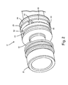
- FIG. 2 is a perspective view of one embodiment of first shaft 12 from bearing lubrication assembly 10. A portion of bearing lubrication assembly 10 is omitted in FIG. 1 so as to fit FIG. 1 on a single page.
- bearing lubrication assembly 10 includes first shaft 12 and second shaft 14.
- first shaft 12 can include first end 15, second end 16, outer surface 18, reservoir 20, first seal groove 22, second seal groove 24, a plurality of chambers 26 with closed bottoms 28, axially extending walls 30 (only labeled in FIG.
- Second shaft 14 is tubular and can include first end 36, second end 38, outer surface 40, inner surface 42, spline member 44, stop 46, and locking groove 48. Second shaft 14 can also include radial port 50 and first shaft 12 can include radial port 52.
- Bearing lubrication assembly 10 can also include first seal 54, second seal 56, bearing inner race 58 with radial fluid inlet 60, bearing outer race 62, bearing element 64, and snap ring 66.
- First shaft 12 extends axially between first end 15 and second end 16.
- Outer surface 18 of first shaft 12 is an outer circumferential surface that extends around an outer circumference of first shaft 12.
- First seal groove 22 is formed on outer surface 18 of first shaft 12 and extends a full circumference of outer surface 18 of first shaft 12.
- Second seal groove 24 is also formed on outer surface 18 of first shaft 12 and extends the full circumference of outer surface 18 of first shaft 12. Second seal groove 24 can be axially spaced from first seal groove 22 on outer surface 18 of first shaft 12 so as to accommodate chambers 26. Chambers 26 are formed on first shaft 12 and disposed axially between first seal groove 22 and second seal groove 24.
- Chambers 26 are open to outer surface 18 of first shaft 12 and each chamber 26 includes closed bottom 28 disposed radially inward from outer surface 18 of first shaft 12. As shown in FIG. 2 , each chamber 26 can be circumferentially spaced from one another around first shaft 12. Axially extending walls 30 separate each chamber 26 from the rest of chambers 26. In preferred embodiments, there are at least three chambers 26, but the number of chambers 26 can vary as desired for particular applications.
- chambers 26 are radially open to outer surface 18, include closed bottoms 28, are separated from one another by axially extending walls 30, and are circumferentially spaced around first shaft 12, chambers 26 can hold fluid similar to a cup and at least some of chambers 26 on first shaft 12 will be oriented in an upward or semi-upward facing position capable of holding and storing some amount of lubricating fluid when first shaft 12 is stationary and not rotating.
- Reservoir 20 can be disposed within first shaft 12 to provide a source of lubricating fluid.
- Reservoir 20 can be a cylindrical bore centered radially within first shaft 12. Reservoir 20 does not intersect chambers 26 and can be disposed radially within from chambers 26.
- at least one radial port 52 can extend radially outward from reservoir 20 toward outer surface 18 of first shaft 12, and intersect outer surface 18 of first shaft 12 between first seal groove 22 and second seal groove 24. Radial port 52 extends from reservoir 20 to outer surface 18 of first shaft 12 without intersecting chambers 26 and can be positioned axially between first seal groove 22 and chambers 26. While FIGS.
- first shaft 12 can include more than one radial port 52.
- First seal 54 can be disposed at least partially in first seal groove 22, and second seal 56 can be disposed at least partially in second seal groove 24.
- First seal 54 and second seal 56 can both be O-rings.
- first seal 54 and second seal 56 provide a seal between first shaft 12 and second shaft 14 that helps prevent fluid leakage between first shaft 12 and second shaft 14 and undesirable foreign particle incursion into bearing lubrication assembly 10.
- Second shaft 14 extends axially between first end 36 and second end 38. Second shaft is also tubular with inner surface 42 disposed radially within outer surface 40. Second shaft 14 is disposed around first shaft 12 such that inner surface 42 of second shaft 14 faces outer surface 18 of first shaft 12. Inner surface 42 of second shaft 14 can include a diameter that is larger than a diameter of outer surface 18 of first shaft 12, such that a gap exists between inner surface 42 of second shaft 14 and outer surface 18 of first shaft 12. First seal 54 and second seal 56 engage inner surface 42 of second shaft 14, thereby fluidically sealing the gap axially between first seal 54 and second seal 56. Radial port 50 can extend radially from inner surface 42 to outer surface 40 of second shaft 14. Radial port 50 can also be axially aligned with chambers 26. While FIG.
- second shaft 14 can include more than one radial port 50.
- Both radial port 50 of second shaft 14 and radial port 52 of first shaft 12 are fluidically connected to the gap disposed radially between inner surface 42 and outer surface 18, and axially between first seal 54 and second seal 56.
- Bearing inner race 58 can be disposed around second shaft 14. Radial fluid inlet 60 can extend across bearing inner race 58 and can also be aligned with radial port 50 of second shaft 14 such that radial fluid inlet 60 is capable of receiving lubricating fluid from radial port 50. While FIG. 1 only shows one radial fluid inlet 60, one skilled in the art will recognize that bearing inner race 58 can include more than one radial fluid inlet 60.
- Bearing outer race 62 can be disposed around bearing inner race 58. Bearing element 64 is disposed between bearing outer race 62 and bearing inner race 58.
- first shaft 12, second shaft 14, and inner race 58 rotate.
- the rotation of first shaft 12 and second shaft 14 generates a centrifugal force that urges lubricating fluid disposed in reservoir 20 into radial port 52 of first shaft 12.
- the lubricating fluid travels radially outward through radial port 52 and into the gap disposed between outer surface 18 of first shaft 12 and inner surface 42 of second shaft 14.
- First seal 54 and second seal 56 help prevent the lubricating fluid from leaking axially outside the gap between first seal 54 and second seal 56.
- the centrifugal force urges the lubricating fluid against inner surface 42 of second shaft 14.
- bearing lubrication assembly 10 can also include additional features for lubricating bearing element 64, such as jets that spray lubricating fluid directly onto bearing inner race 58, bearing outer race 62, and bearing element 64.
- first shaft 12, second shaft 14, and bearing inner race 58 cease to rotate.
- the centrifugal force that urges the lubrication fluid radially outward dissipates.
- gravitational forces can cause at least some of the lubricating fluid presently disposed on inner surface 42 of second shaft 14 and the lubricating fluid disposed inside radial port 50 of second shaft 14 to fall radially inward and onto first shaft 12.
- lubricating fluid falls from second shaft 14 to first shaft 12
- at least some of that lubricating fluid falls inside those of chambers 26 whose openings are positioned (gravitationally) upward or partially upward at the time first shaft 12, second shaft 14, and bearing inner race 58 stopped rotating.
- the lubricating fluid captured by chambers 26 is stored inside chambers 26 until machine startup when first shaft 12, second shaft 14, and bearing inner race 58 begin rotating again.
- the lubricating fluid not captured by chambers 26 can flow to the bottom (gravitationally) of the gap disposed radially between inner surface 42 and outer surface 18, and axially between first seal 54 and second seal 56, and await there until machine startup when first shaft 12, second shaft 14, and bearing inner race 58 begin rotating again.
- first shaft 12, second shaft 14, and bearing inner race 58 begin rotating again, the centrifugal force generated by the rotation of first shaft 12 and second shaft 14 forces the lubricating fluid stored inside chambers 26 to move radially outward onto inner surface 42 of second shaft 14 and into radial port 50 of second shaft 14.
- the lubricating fluid then flows into radial fluid inlet 60 and continues on to bearing element 64 and bearing outer race 62.
- the lubricating fluid that traveled from chambers 26 to bearing element 64 can lubricate bearing inner race 58, bearing outer race 62, and bearing element 64 before lubricating fluid disposed in reservoir 20 reaches bearing element 64, thereby reducing the duration of time that bearing element 64 rotates at machine startup without lubrication.
- Reducing the amount of time that bearing element 64 rotates without lubrication helps minimize the wear experienced between bearing inner race 58, bearing outer race 62, and bearing element 64 and thereby increases the operating life of bearing inner race 58, bearing outer race 62, and bearing element 64.
- First shaft 12 and second shaft 14 can be rotationally fixed to one another such that first shaft 12 and second shaft 14 do not rotate relative to one another, thereby ensuring that they rotate at the same speed during machine operation.
- radially outward extending spline 34 can be formed on first shaft 12 proximate second end 16 of first shaft 12.
- Radially inward extending spline 44 can be formed on second shaft 14 proximate second end 38 of second shaft 14.
- Radially outward extending spline 34 of first shaft 12 engages with radially inward extending spline 44 of second shaft 14.
- Second shaft 14 can include additional features, such as stop 46 and locking groove 48, that aid in axially positioning first shaft 12 relative second shaft 14.
- Stop 46 can extend radially inward from inner surface 42 of second shaft 14 between first end 36 and second end 38 of second shaft 14. Stop 46 engages first shaft 12 between second seal groove 24 and second end 16 of first shaft 12.
- First shaft 12 can include a reduced diameter region between second seal groove 24 and second end 16 that includes a diameter smaller than a diameter of outer surface 18 of first shaft 12 so as to create ledge 35 on first shaft 12.
- Ledge 35 on first shaft 12 can engage stop 46 of second shaft 14.
- Locking groove 48 can be formed in second shaft 14 and extend radially outward from inner surface 42 of second shaft 14.
- First seal groove 22 and second seal groove 24 of first shaft 12 are axially positioned between locking groove 48 and stop 46 of second shaft 14.
- Snap ring 66 can be disposed in locking groove 48 and extends radially inward to engage first shaft 12. Together, stop 46, ledge 35, locking groove 48, and snap ring 66 axially restrain first shaft 12 relative second shaft 14 and ensure that radial port 50 of second shaft 14 is properly positioned proximate chambers 26.
- First shaft 12 can also include shear section 32. Shear section 32 can be positioned on first shaft 12 between first end 15 of first shaft 12 and first seal groove 22. Shear section 32 acts as a fail-safe mechanism that allows first shaft 12 to shear at shear section 32 to protect components connected to first shaft 12 should first shaft 12 experience a predetermined level of shear stress.
- first end 15 of first shaft 12 can be connected to a gear box of an auxiliary power unit (APU) for an aircraft, and second end 16 of first shaft 12 can be connected to a generator.
- APU auxiliary power unit
- first shaft 12 will shear at shear section 32 to protect the generator from experiencing too much stress.
- bearing lubrication assembly 10 of the present invention can provide numerous advantages and benefits. Some examples of those advantages and benefits are as follows. Chambers 26 store lubricating fluid in relatively close proximity to bearing element 64 at machine shutdown. At machine startup, chambers 26 deliver the stored lubricating fluid relatively quickly to bearing element 64 so that bearing element 64, bearing inner race 58, and bearing outer race 62 are lubricated quickly at startup and do not have to wait for lubrication to be delivered from reservoir 20. Providing lubricating fluid to bearing element 64, bearing inner race 58, and bearing outer race 62 quickly at startup can reduce the wear and increase the life of bearing element 64, bearing inner race 58, and bearing outer race 62. Furthermore, first seal 54 and second seal 56 reduce the likelihood of foreign contaminants entering the lubricating fluid and increasing the wear on bearing element 64, bearing inner race 58, and bearing outer race 62.
- a shaft for a bearing lubrication assembly includes an outer surface and a reservoir disposed within the shaft.
- a first seal groove is formed on the outer surface and extends a full circumference of the outer surface.
- a second seal groove is also formed on the outer surface and extends the full circumference of the outer surface.
- a radial port extends from the reservoir to the outer surface, the radial port intersecting the outer surface between the first seal groove and the second seal groove.
- a plurality of chambers are formed in the shaft and disposed axially between the first seal groove and the second seal groove. The plurality of chambers are open to the outer surface with each chamber having a closed bottom disposed radially inward from the outer surface. Each chamber is also circumferentially spaced from one another.
- the shaft of the preceding paragraph can optionally include, additionally and/or alternatively, any one or more of the following features, configurations and/or additional components.
- the reservoir may be a cylindrical bore centered within the shaft.
- the radial port may be positioned axially between the first seal groove and the plurality of chambers.
- the plurality of chambers may comprise at least three chambers.
- Each of the plurality of chambers may be separated from one another by axially extending walls.
- the shaft further may include a shear section and a spline, and the first seal groove, the second seal groove, and the plurality of chambers may be disposed on the shaft between the shear section and the spline.
- a bearing lubrication assembly in another embodiment, includes a first shaft with an outer surface, a first seal groove formed on the outer surface and extending a full circumference of the outer surface, and a second seal groove formed on the outer surface and also extending the full circumference of the outer surface.
- a plurality of chambers are formed in the shaft and disposed axially between the first seal groove and the second seal groove. The plurality of chambers are open to the outer surface with each chamber having a closed bottom disposed radially inward from the outer surface. Each chamber is also circumferentially spaced from one another.
- the bearing lubrication assembly also includes a tubular second shaft disposed around the first shaft.
- the second shaft includes an outer surface, an inner surface, and a first radial port that extends from the inner surface to the outer surface of the second shaft.
- the first radial port is axially aligned with the plurality of chambers.
- the assembly of the preceding paragraph can optionally include, additionally and/or alternatively, any one or more of the following steps, features, and/or configurations.
- a first seal may be disposed at least partially in the first seal groove, and a second seal disposed at least partially in the second seal groove.
- the first shaft and the second shaft may be connected such that the first shaft and the second shaft are rotationally fixed relative one another.
- a spline connection may be configured to engage the first and second shafts together.
- a bearing inner race may be disposed around the second shaft and have a radial fluid inlet aligned with the first radial port.
- a gap may be disposed between the outer surface of the first shaft and the inner surface of the second shaft.
- a reservoir may be disposed within the shaft and a second radial port extend from the reservoir to the outer surface of the first shaft, the second radial port intersecting the outer surface of the first shaft between the first seal groove and the second seal groove.
- a stop may extend radially inward from the inner surface of the second shaft and engages the first shaft.
- a locking groove may extend radially outward from the inner surface of the second shaft.
- a snap ring may be disposed in the locking groove.
- the first seal groove and the second seal groove of the first shaft may be axially positioned between the locking groove and the stop.
- first shaft 12 and second shaft 14 being connected by a spline connection
- first shaft 12 and second shaft 14 can alternately be connected by a threaded connection, a braze, lock pins, or any other means that rotationally fixes first shaft 12 and second shaft 14 together. Therefore, it is intended that the invention not be limited to the particular embodiment(s) disclosed, but that the invention will include all embodiments falling within the scope of the appended claims.
Landscapes
- Engineering & Computer Science (AREA)
- General Engineering & Computer Science (AREA)
- Mechanical Engineering (AREA)
- Ocean & Marine Engineering (AREA)
- Rolling Contact Bearings (AREA)
- General Details Of Gearings (AREA)
Abstract
Description
- The present invention relates to bearing lubrication and more specifically to the lubrication of bearings at startup of a machine utilizing the bearings (machine startup).
- Bearings in rotating machinery usually require some type of lubricant to ensure long life and proper function. Bearing lubrication is critical, especially in applications where the bearings experience high speeds, high loads, and/or high temperatures, such as in aircraft electrical power generators. In aircraft electrical power generators and similar applications, a pump delivers lubricating fluid supply from a lubrication reservoir to the bearings. During machine startup, lubricant delivery to the bearings may take some time as the pump pressurizes the lubricating fluid, resulting in the bearings rotating with insufficient lubrication for a period of time. Whenever the bearings rotate at machine startup without sufficient lubrication, the bearings experience a significant amount of wear. It is therefore critical to deliver lubrication to the bearings as soon as possible during machine startup so as to reduce bearing wear.
- In one aspect, a shaft for a bearing lubrication assembly includes an outer surface and a reservoir disposed within the shaft. A first seal groove is formed on the outer surface and extends a full circumference of the outer surface. A second seal groove is also formed on the outer surface and extends the full circumference of the outer surface. A radial port extends from the reservoir to the outer surface, the radial port intersecting the outer surface between the first seal groove and the second seal groove. A plurality of chambers are formed in the shaft and disposed axially between the first seal groove and the second seal groove. The plurality of chambers are open to the outer surface with each chamber having a closed bottom disposed radially inward from the outer surface. Each chamber is also circumferentially spaced from one another.
- In another aspect, a bearing lubrication assembly includes a first shaft with an outer surface, a first seal groove formed on the outer surface and extending a full circumference of the outer surface, and a second seal groove formed on the outer surface and also extending the full circumference of the outer surface. A plurality of chambers are formed in the shaft and disposed axially between the first seal groove and the second seal groove. The plurality of chambers are open to the outer surface with each chamber having a closed bottom disposed radially inward from the outer surface. Each chamber is also circumferentially spaced from one another. The bearing lubrication assembly also includes a tubular second shaft disposed around the first shaft. The second shaft includes an outer surface, an inner surface, and a first radial port that extends from the inner surface to the outer surface of the second shaft. The first radial port is axially aligned with the plurality of chambers.
- Persons of ordinary skill in the art will recognize that other aspects and embodiments of the present invention are possible in view of the entirety of the present disclosure, including the accompanying figures.
-
-
FIG. 1 is a cross-sectional view of an embodiment of a bearing lubrication assembly. -
FIG. 2 is a perspective view of an embodiment of an inner shaft from the bearing lubrication assembly ofFIG. 1 . - While the above-identified drawing figures set forth one or more embodiments of the invention, other embodiments are also contemplated. In all cases, this disclosure presents the invention by way of representation and not limitation. It should be understood that numerous other modifications and embodiments can be devised by those skilled in the art, which fall within the scope of the invention. The figures may not be drawn to scale, and applications and embodiments of the present invention may include features and components not specifically shown in the drawings.
- In at least some embodiments, the present invention relates generally to a bearing lubrication assembly that includes a first shaft disposed within a second shaft. The first shaft includes a plurality of chambers formed on its outer surface and disposed between two axially spaced seals. A bearing assembly is disposed around the second shaft. A reservoir delivers lubricating fluid between the first shaft and the second shaft. A radial port formed in the second shaft directs the lubricating fluid disposed between the two shafts into the bearing assembly. When the bearing lubrication assembly powers down, lubricating fluid is captured and stored in the plurality of chambers to be used during machine startup to lubricate the bearing assembly so that the bearing assembly does not have to rotate without lubrication while the lubrication assembly achieves steady-state. Persons of ordinary skill in the art will recognize additional features and benefits in view of the entirety of the present disclosure, including the accompanying figures.
-
FIGS. 1 and2 will be discussed concurrently.FIG. 1 is a cross-sectional view of one embodiment ofbearing lubrication assembly 10, andFIG. 2 is a perspective view of one embodiment offirst shaft 12 frombearing lubrication assembly 10. A portion ofbearing lubrication assembly 10 is omitted inFIG. 1 so as to fitFIG. 1 on a single page. As shown inFIG. 1 ,bearing lubrication assembly 10 includesfirst shaft 12 andsecond shaft 14. As shown in bothFIGS. 1 and2 ,first shaft 12 can includefirst end 15,second end 16,outer surface 18,reservoir 20,first seal groove 22,second seal groove 24, a plurality ofchambers 26 with closedbottoms 28, axially extending walls 30 (only labeled inFIG. 2 ),shear section 32,spline member 34, andledge 35.Second shaft 14 is tubular and can includefirst end 36,second end 38,outer surface 40,inner surface 42,spline member 44,stop 46, andlocking groove 48.Second shaft 14 can also includeradial port 50 andfirst shaft 12 can includeradial port 52.Bearing lubrication assembly 10 can also includefirst seal 54,second seal 56, bearinginner race 58 withradial fluid inlet 60, bearingouter race 62,bearing element 64, andsnap ring 66. -
First shaft 12 extends axially betweenfirst end 15 andsecond end 16.Outer surface 18 offirst shaft 12 is an outer circumferential surface that extends around an outer circumference offirst shaft 12.First seal groove 22 is formed onouter surface 18 offirst shaft 12 and extends a full circumference ofouter surface 18 offirst shaft 12.Second seal groove 24 is also formed onouter surface 18 offirst shaft 12 and extends the full circumference ofouter surface 18 offirst shaft 12.Second seal groove 24 can be axially spaced fromfirst seal groove 22 onouter surface 18 offirst shaft 12 so as to accommodatechambers 26.Chambers 26 are formed onfirst shaft 12 and disposed axially betweenfirst seal groove 22 andsecond seal groove 24.Chambers 26 are open toouter surface 18 offirst shaft 12 and eachchamber 26 includes closedbottom 28 disposed radially inward fromouter surface 18 offirst shaft 12. As shown inFIG. 2 , eachchamber 26 can be circumferentially spaced from one another aroundfirst shaft 12. Axially extendingwalls 30 separate eachchamber 26 from the rest ofchambers 26. In preferred embodiments, there are at least threechambers 26, but the number ofchambers 26 can vary as desired for particular applications. As discussed in detail below, becausechambers 26 are radially open toouter surface 18, include closedbottoms 28, are separated from one another by axially extendingwalls 30, and are circumferentially spaced aroundfirst shaft 12,chambers 26 can hold fluid similar to a cup and at least some ofchambers 26 onfirst shaft 12 will be oriented in an upward or semi-upward facing position capable of holding and storing some amount of lubricating fluid whenfirst shaft 12 is stationary and not rotating. -
Reservoir 20 can be disposed withinfirst shaft 12 to provide a source of lubricating fluid.Reservoir 20 can be a cylindrical bore centered radially withinfirst shaft 12.Reservoir 20 does not intersectchambers 26 and can be disposed radially within fromchambers 26. As shown inFIG. 1 , at least oneradial port 52 can extend radially outward fromreservoir 20 towardouter surface 18 offirst shaft 12, and intersectouter surface 18 offirst shaft 12 betweenfirst seal groove 22 andsecond seal groove 24.Radial port 52 extends fromreservoir 20 toouter surface 18 offirst shaft 12 without intersectingchambers 26 and can be positioned axially betweenfirst seal groove 22 andchambers 26. WhileFIGS. 1 and2 only show oneradial port 52, one skilled in the art will recognize thatfirst shaft 12 can include more than oneradial port 52.First seal 54 can be disposed at least partially infirst seal groove 22, andsecond seal 56 can be disposed at least partially insecond seal groove 24.First seal 54 andsecond seal 56 can both be O-rings. As discussed below,first seal 54 andsecond seal 56 provide a seal betweenfirst shaft 12 andsecond shaft 14 that helps prevent fluid leakage betweenfirst shaft 12 andsecond shaft 14 and undesirable foreign particle incursion into bearinglubrication assembly 10. -
Second shaft 14 extends axially betweenfirst end 36 andsecond end 38. Second shaft is also tubular withinner surface 42 disposed radially withinouter surface 40.Second shaft 14 is disposed aroundfirst shaft 12 such thatinner surface 42 ofsecond shaft 14 facesouter surface 18 offirst shaft 12.Inner surface 42 ofsecond shaft 14 can include a diameter that is larger than a diameter ofouter surface 18 offirst shaft 12, such that a gap exists betweeninner surface 42 ofsecond shaft 14 andouter surface 18 offirst shaft 12.First seal 54 andsecond seal 56 engageinner surface 42 ofsecond shaft 14, thereby fluidically sealing the gap axially betweenfirst seal 54 andsecond seal 56.Radial port 50 can extend radially frominner surface 42 toouter surface 40 ofsecond shaft 14.Radial port 50 can also be axially aligned withchambers 26. WhileFIG. 1 only shows oneradial port 50, one skilled in the art will recognize thatsecond shaft 14 can include more than oneradial port 50. Bothradial port 50 ofsecond shaft 14 andradial port 52 offirst shaft 12 are fluidically connected to the gap disposed radially betweeninner surface 42 andouter surface 18, and axially betweenfirst seal 54 andsecond seal 56. - Bearing
inner race 58 can be disposed aroundsecond shaft 14. Radialfluid inlet 60 can extend across bearinginner race 58 and can also be aligned withradial port 50 ofsecond shaft 14 such that radialfluid inlet 60 is capable of receiving lubricating fluid fromradial port 50. WhileFIG. 1 only shows oneradial fluid inlet 60, one skilled in the art will recognize that bearinginner race 58 can include more than oneradial fluid inlet 60. Bearingouter race 62 can be disposed around bearinginner race 58. Bearingelement 64 is disposed between bearingouter race 62 and bearinginner race 58. - During operation of bearing
lubrication assembly 10,first shaft 12,second shaft 14, andinner race 58 rotate. The rotation offirst shaft 12 andsecond shaft 14 generates a centrifugal force that urges lubricating fluid disposed inreservoir 20 intoradial port 52 offirst shaft 12. The lubricating fluid travels radially outward throughradial port 52 and into the gap disposed betweenouter surface 18 offirst shaft 12 andinner surface 42 ofsecond shaft 14.First seal 54 andsecond seal 56 help prevent the lubricating fluid from leaking axially outside the gap betweenfirst seal 54 andsecond seal 56. Inside the gap betweenfirst shaft 12 andsecond shaft 14 and betweenfirst seal 54 andsecond seal 56, the centrifugal force urges the lubricating fluid againstinner surface 42 ofsecond shaft 14. The lubricating fluid is then urged intoradial port 50 ofsecond shaft 14 where it travels radially outward and intoradial fluid inlet 60 of bearinginner race 58. The lubricating fluid then travels acrossradial fluid inlet 60 and exitsradial fluid inlet 60 between bearinginner race 58 and bearingouter race 62 where it lubricates bearingelement 64.Bearing lubrication assembly 10 can also include additional features for lubricating bearingelement 64, such as jets that spray lubricating fluid directly onto bearinginner race 58, bearingouter race 62, and bearingelement 64. - During machine shutdown,
first shaft 12,second shaft 14, and bearinginner race 58 cease to rotate. Asfirst shaft 12,second shaft 14, andinner race 58 cease to rotate, the centrifugal force that urges the lubrication fluid radially outward dissipates. Once the centrifugal force dissipates, gravitational forces can cause at least some of the lubricating fluid presently disposed oninner surface 42 ofsecond shaft 14 and the lubricating fluid disposed insideradial port 50 ofsecond shaft 14 to fall radially inward and ontofirst shaft 12. As lubricating fluid falls fromsecond shaft 14 tofirst shaft 12, at least some of that lubricating fluid falls inside those ofchambers 26 whose openings are positioned (gravitationally) upward or partially upward at the timefirst shaft 12,second shaft 14, and bearinginner race 58 stopped rotating. The lubricating fluid captured bychambers 26 is stored insidechambers 26 until machine startup whenfirst shaft 12,second shaft 14, and bearinginner race 58 begin rotating again. The lubricating fluid not captured bychambers 26 can flow to the bottom (gravitationally) of the gap disposed radially betweeninner surface 42 andouter surface 18, and axially betweenfirst seal 54 andsecond seal 56, and await there until machine startup whenfirst shaft 12,second shaft 14, and bearinginner race 58 begin rotating again. - At machine startup, when
first shaft 12,second shaft 14, and bearinginner race 58 begin rotating again, the centrifugal force generated by the rotation offirst shaft 12 andsecond shaft 14 forces the lubricating fluid stored insidechambers 26 to move radially outward ontoinner surface 42 ofsecond shaft 14 and intoradial port 50 ofsecond shaft 14. The lubricating fluid then flows intoradial fluid inlet 60 and continues on to bearingelement 64 and bearingouter race 62. The lubricating fluid that traveled fromchambers 26 to bearingelement 64 can lubricate bearinginner race 58, bearingouter race 62, and bearingelement 64 before lubricating fluid disposed inreservoir 20reaches bearing element 64, thereby reducing the duration of time that bearingelement 64 rotates at machine startup without lubrication. Reducing the amount of time that bearingelement 64 rotates without lubrication helps minimize the wear experienced between bearinginner race 58, bearingouter race 62, and bearingelement 64 and thereby increases the operating life of bearinginner race 58, bearingouter race 62, and bearingelement 64. -
First shaft 12 andsecond shaft 14 can be rotationally fixed to one another such thatfirst shaft 12 andsecond shaft 14 do not rotate relative to one another, thereby ensuring that they rotate at the same speed during machine operation. As shown inFIG. 1 , radially outward extendingspline 34 can be formed onfirst shaft 12 proximatesecond end 16 offirst shaft 12. Radially inward extendingspline 44 can be formed onsecond shaft 14 proximatesecond end 38 ofsecond shaft 14. Radially outward extendingspline 34 offirst shaft 12 engages with radially inward extendingspline 44 ofsecond shaft 14. Together, radially outward extendingspline 34 and radially inward extendingspline 44 form a spline connection betweenfirst shaft 12 andsecond shaft 14 that rotationally fixessecond shaft 14 tofirst shaft 12.Second shaft 14 can include additional features, such asstop 46 and lockinggroove 48, that aid in axially positioningfirst shaft 12 relativesecond shaft 14. -
Stop 46 can extend radially inward frominner surface 42 ofsecond shaft 14 betweenfirst end 36 andsecond end 38 ofsecond shaft 14.Stop 46 engagesfirst shaft 12 betweensecond seal groove 24 andsecond end 16 offirst shaft 12.First shaft 12 can include a reduced diameter region betweensecond seal groove 24 andsecond end 16 that includes a diameter smaller than a diameter ofouter surface 18 offirst shaft 12 so as to createledge 35 onfirst shaft 12.Ledge 35 onfirst shaft 12 can engage stop 46 ofsecond shaft 14. Lockinggroove 48 can be formed insecond shaft 14 and extend radially outward frominner surface 42 ofsecond shaft 14.First seal groove 22 andsecond seal groove 24 offirst shaft 12 are axially positioned between lockinggroove 48 and stop 46 ofsecond shaft 14.Snap ring 66 can be disposed in lockinggroove 48 and extends radially inward to engagefirst shaft 12. Together, stop 46,ledge 35, lockinggroove 48, andsnap ring 66 axially restrainfirst shaft 12 relativesecond shaft 14 and ensure thatradial port 50 ofsecond shaft 14 is properly positionedproximate chambers 26.First shaft 12 can also includeshear section 32.Shear section 32 can be positioned onfirst shaft 12 betweenfirst end 15 offirst shaft 12 andfirst seal groove 22.Shear section 32 acts as a fail-safe mechanism that allowsfirst shaft 12 to shear atshear section 32 to protect components connected tofirst shaft 12 shouldfirst shaft 12 experience a predetermined level of shear stress. For example,first end 15 offirst shaft 12 can be connected to a gear box of an auxiliary power unit (APU) for an aircraft, andsecond end 16 offirst shaft 12 can be connected to a generator. Should the APU generate an undesirable level of shear stress infirst shaft 12,first shaft 12 will shear atshear section 32 to protect the generator from experiencing too much stress. - Persons of ordinary skill in the art will recognize that bearing
lubrication assembly 10 of the present invention can provide numerous advantages and benefits. Some examples of those advantages and benefits are as follows.Chambers 26 store lubricating fluid in relatively close proximity to bearingelement 64 at machine shutdown. At machine startup,chambers 26 deliver the stored lubricating fluid relatively quickly to bearingelement 64 so that bearingelement 64, bearinginner race 58, and bearingouter race 62 are lubricated quickly at startup and do not have to wait for lubrication to be delivered fromreservoir 20. Providing lubricating fluid to bearingelement 64, bearinginner race 58, and bearingouter race 62 quickly at startup can reduce the wear and increase the life of bearingelement 64, bearinginner race 58, and bearingouter race 62. Furthermore,first seal 54 andsecond seal 56 reduce the likelihood of foreign contaminants entering the lubricating fluid and increasing the wear on bearingelement 64, bearinginner race 58, and bearingouter race 62. - The following are non-exclusive descriptions of possible embodiments of the present invention.
- In one embodiment, a shaft for a bearing lubrication assembly includes an outer surface and a reservoir disposed within the shaft. A first seal groove is formed on the outer surface and extends a full circumference of the outer surface. A second seal groove is also formed on the outer surface and extends the full circumference of the outer surface. A radial port extends from the reservoir to the outer surface, the radial port intersecting the outer surface between the first seal groove and the second seal groove. A plurality of chambers are formed in the shaft and disposed axially between the first seal groove and the second seal groove. The plurality of chambers are open to the outer surface with each chamber having a closed bottom disposed radially inward from the outer surface. Each chamber is also circumferentially spaced from one another.
- The shaft of the preceding paragraph can optionally include, additionally and/or alternatively, any one or more of the following features, configurations and/or additional components.
- The reservoir may be a cylindrical bore centered within the shaft.
- The radial port may be positioned axially between the first seal groove and the plurality of chambers.
- The plurality of chambers may comprise at least three chambers.
- Each of the plurality of chambers may be separated from one another by axially extending walls.
- The shaft further may include a shear section and a spline, and the first seal groove, the second seal groove, and the plurality of chambers may be disposed on the shaft between the shear section and the spline.
- In another embodiment, a bearing lubrication assembly includes a first shaft with an outer surface, a first seal groove formed on the outer surface and extending a full circumference of the outer surface, and a second seal groove formed on the outer surface and also extending the full circumference of the outer surface. A plurality of chambers are formed in the shaft and disposed axially between the first seal groove and the second seal groove. The plurality of chambers are open to the outer surface with each chamber having a closed bottom disposed radially inward from the outer surface. Each chamber is also circumferentially spaced from one another. The bearing lubrication assembly also includes a tubular second shaft disposed around the first shaft. The second shaft includes an outer surface, an inner surface, and a first radial port that extends from the inner surface to the outer surface of the second shaft. The first radial port is axially aligned with the plurality of chambers.
- The assembly of the preceding paragraph can optionally include, additionally and/or alternatively, any one or more of the following steps, features, and/or configurations.
- A first seal may be disposed at least partially in the first seal groove, and a second seal disposed at least partially in the second seal groove.
- The first shaft and the second shaft may be connected such that the first shaft and the second shaft are rotationally fixed relative one another.
- A spline connection may be configured to engage the first and second shafts together.
- A bearing inner race may be disposed around the second shaft and have a radial fluid inlet aligned with the first radial port.
- A gap may be disposed between the outer surface of the first shaft and the inner surface of the second shaft.
- A reservoir may be disposed within the shaft and a second radial port extend from the reservoir to the outer surface of the first shaft, the second radial port intersecting the outer surface of the first shaft between the first seal groove and the second seal groove.
- A stop may extend radially inward from the inner surface of the second shaft and engages the first shaft.
- A locking groove may extend radially outward from the inner surface of the second shaft.
- A snap ring may be disposed in the locking groove.
- The first seal groove and the second seal groove of the first shaft may be axially positioned between the locking groove and the stop.
- Any relative terms or terms of degree used herein, such as "substantially", "essentially", "generally" and the like, should be interpreted in accordance with and subject to any applicable definitions or limits expressly stated herein. In all instances, any relative terms or terms of degree used herein should be interpreted to broadly encompass any relevant disclosed embodiments as well as such ranges or variations as would be understood by a person of ordinary skill in the art in view of the entirety of the present disclosure, such as to encompass ordinary manufacturing tolerance variations, incidental alignment variations, transitory vibrations and sway movements, temporary alignment or shape variations induced by operational conditions, and the like.
- While the invention has been described with reference to an exemplary embodiment(s), it will be understood by those skilled in the art that various changes may be made and equivalents may be substituted for elements thereof without departing from the scope of the invention. In addition, many modifications may be made to adapt a particular situation or material to the teachings of the invention without departing from the essential scope thereof. For example, while the above description describes
first shaft 12 andsecond shaft 14 being connected by a spline connection,first shaft 12 andsecond shaft 14 can alternately be connected by a threaded connection, a braze, lock pins, or any other means that rotationally fixesfirst shaft 12 andsecond shaft 14 together. Therefore, it is intended that the invention not be limited to the particular embodiment(s) disclosed, but that the invention will include all embodiments falling within the scope of the appended claims.
Claims (15)
- A shaft (12) for a bearing lubrication assembly, the shaft comprising:an outer surface (18);a reservoir (20) disposed within the shaft (12);a first seal groove (22) formed on the outer surface (18) and extending a full circumference of the outer surface (18);a second seal groove (24) formed on the outer surface (18) and extending a full circumference of the outer surface (18);a radial port (52) extending from the reservoir (20) to the outer surface (18), the radial port (52) intersecting the outer surface (18) between the first seal groove (22) and the second seal groove (24); anda plurality of chambers (26) formed in the shaft (12) and disposed axially between the first seal groove (22) and the second seal groove (24), the plurality of chambers (26) being open to the outer surface (18), each chamber (26) having a closed bottom (28) disposed radially inward from the outer surface (18), and each chamber (26) being circumferentially spaced from one another.
- The shaft of claim 1, wherein the reservoir (20) is a cylindrical bore centered within the shaft.
- The shaft of claim 1 or 2, wherein the radial port (52) is positioned axially between the first seal groove (22) and the plurality of chambers (26).
- The shaft of any preceding claim, wherein the plurality of chambers (26) comprises at least three chambers (26).
- The shaft of any preceding claim, wherein each of the plurality of chambers (26) are separated from one another by axially extending walls (30).
- The shaft of any preceding claim further comprising a shear section (32); and
a spline (34),
wherein the first seal groove (22), the second seal groove (24), and the plurality of chambers (26) are disposed on the shaft (12) between the shear section (32) and the spline (34). - A bearing lubrication assembly comprising:a first shaft (12) of any preceding claim;and a tubular second shaft (14) disposed around the first shaft (12), the second
shaft (14) comprising:an outer surface (40);an inner surface (42); anda first radial port that extends from the inner surface (42) to the outer surface (40) of the second shaft (14), the first radial port (50) being axially aligned with the plurality of chambers (26). - A bearing lubrication assembly comprising:a first shaft (12) comprising:an outer surface (18);a first seal groove (22) formed on the outer surface (18) and extending a full circumference of the outer surface (18);a second seal groove (24) formed on the outer surface (18) and extending a full circumference of the outer surface (18);a plurality of chambers (26) formed in the shaft (12) and disposed axially between the first seal groove (22) and the second seal groove (24), the plurality of chambers (26) being open to the outer surface (18), each chamber (26) having a closed bottom (28) disposed radially inward from the outer surface (18), and each chamber (26) being circumferentially spaced from one another; anda tubular second shaft (14) disposed around the first shaft (12), the second shaft (14) comprising:an outer surface (40);an inner surface (42); anda first radial port that extends from the inner surface (42) to the outer surface (40) of the second shaft (14), the first radial port (50) being axially aligned with the plurality of chambers (26).
- The bearing lubrication assembly of claim 7 or 8 further comprising:a first seal (54) disposed at least partially in the first seal groove (22); anda second seal (56) disposed at least partially in the second seal groove (24).
- The bearing lubrication assembly of claim 7, 8 or 9, wherein the first shaft (12) and the second shaft (14) are connected such that the first shaft (12) and the second shaft (14) are rotationally fixed relative one another.
- The bearing lubrication assembly of claim 10 further comprising:a spline connection configured to engage the first and second shafts (12,14) together.
- The bearing lubrication assembly of any of claims 7 to 11 further comprising:a bearing inner race (58) disposed around the second shaft (14), the bearing inner race (58) comprising:a radial fluid inlet (60) aligned with the first radial port (50);a gap disposed between the outer surface (18) of the first shaft (12) and the inner surface (42) of the second shaft (14); andthe first shaft (12) further comprising:a reservoir (20) disposed within the first shaft (12); anda second radial port (52) extending from the reservoir (20) to the outer surface (18) of the first shaft (12), the second radial port (52) intersecting the outer surface (18) of the first shaft (12) between the first seal groove (22) and the second seal groove (24).
- The bearing lubrication assembly of any of claims 7 to 12, wherein the second shaft (14) further comprises:a stop (46) that extends radially inward from the inner surface (40) of the second shaft (14) and engages the first shaft (12); anda locking groove (48) extending radially outward from the inner surface (40) of the second shaft (14).
- The bearing lubrication assembly of claim 13, wherein a snap ring (66) is disposed in the locking groove (48).
- The bearing lubrication assembly of claim 13 or 14, wherein the first seal groove (22) and the second seal groove (24) of the first shaft (12) are axially positioned between the locking groove (48) and the stop (46).
Applications Claiming Priority (2)
| Application Number | Priority Date | Filing Date | Title |
|---|---|---|---|
| US201361894693P | 2013-10-23 | 2013-10-23 | |
| US14/182,179 US9103376B2 (en) | 2013-10-23 | 2014-02-17 | Chambered shaft for improved bearing lubrication |
Publications (2)
| Publication Number | Publication Date |
|---|---|
| EP2865904A1 true EP2865904A1 (en) | 2015-04-29 |
| EP2865904B1 EP2865904B1 (en) | 2018-07-25 |
Family
ID=51751980
Family Applications (1)
| Application Number | Title | Priority Date | Filing Date |
|---|---|---|---|
| EP14189530.0A Active EP2865904B1 (en) | 2013-10-23 | 2014-10-20 | Chambered shaft for improved bearing lubrication |
Country Status (2)
| Country | Link |
|---|---|
| US (1) | US9103376B2 (en) |
| EP (1) | EP2865904B1 (en) |
Cited By (2)
| Publication number | Priority date | Publication date | Assignee | Title |
|---|---|---|---|---|
| EP4446600A1 (en) * | 2023-03-30 | 2024-10-16 | Honda Motor Co., Ltd. | Rotating shaft |
| US12633799B2 (en) | 2023-03-30 | 2026-05-19 | Honda Motor Co., Ltd. | Rotating shaft |
Families Citing this family (2)
| Publication number | Priority date | Publication date | Assignee | Title |
|---|---|---|---|---|
| US9755484B2 (en) * | 2014-12-15 | 2017-09-05 | Hamilton Sundstrand Corporation | Methods and systems of air bubble flushing in liquid cooled generators |
| DE102017223375A1 (en) * | 2017-12-20 | 2019-06-27 | Deere & Company | Agricultural machine |
Citations (3)
| Publication number | Priority date | Publication date | Assignee | Title |
|---|---|---|---|---|
| EP1406026A1 (en) * | 2002-10-01 | 2004-04-07 | Snecma Moteurs | Oil-film damped roller bearing |
| JP2004251308A (en) * | 2003-02-18 | 2004-09-09 | Koyo Seiko Co Ltd | Double row roller bearing and lubricating structure for double row roller bearing |
| EP2093439A1 (en) * | 2008-02-25 | 2009-08-26 | Hamilton Sundstrand Corporation | Frustoconical ball bearing and preloaded ball bearing assemblies |
Family Cites Families (20)
| Publication number | Priority date | Publication date | Assignee | Title |
|---|---|---|---|---|
| US1835877A (en) * | 1928-09-20 | 1931-12-08 | Bryan P Joyce | Packing |
| US2283871A (en) * | 1939-11-29 | 1942-05-19 | Allis Chalmers Mfg Co | Bearing |
| US2997962A (en) * | 1958-05-08 | 1961-08-29 | Gen Motors Corp | Pump |
| US3500961A (en) * | 1968-01-16 | 1970-03-17 | Hale Fire Pump Co | Pressure balanced bearing lubrication system |
| US3543647A (en) * | 1969-05-02 | 1970-12-01 | Deere & Co | Control valve means for a two-way hydraulic cylinder |
| US3543536A (en) * | 1969-05-23 | 1970-12-01 | Russell N Rekow | Oil-filled telescoping drive line |
| GB1294898A (en) * | 1969-12-13 | 1972-11-01 | ||
| US4174031A (en) * | 1978-03-27 | 1979-11-13 | Rexnord Inc. | Lubricating system and method |
| DE2829150A1 (en) * | 1978-07-03 | 1980-01-24 | Barmag Barmer Maschf | EXHAUST TURBOCHARGER |
| US4308729A (en) * | 1980-04-02 | 1982-01-05 | Twin Disc, Incorporated | Universal joint slip spline connection having concentric one-way valves |
| DE59405170D1 (en) * | 1993-11-30 | 1998-03-05 | Pelikan Ag | Writing instrument, in particular fountain pens |
| IT1269968B (en) * | 1994-06-29 | 1997-04-16 | Angelo Gambini | HYDRAULIC JOINT WITH DELAY CHAMBER AND TANK |
| CA2187578C (en) * | 1996-10-10 | 2003-02-04 | Vern Arthur Hult | Pump drive head |
| JP3831158B2 (en) * | 1999-09-20 | 2006-10-11 | ジヤトコ株式会社 | Tapered roller bearing lubrication structure |
| US8464850B2 (en) * | 2006-11-16 | 2013-06-18 | Fox Factory, Inc. | Gas spring curve control in an adjustable-volume gas-pressurized device |
| US7793499B2 (en) * | 2006-10-25 | 2010-09-14 | Honeywell International Inc. | Bearing spacer and housing |
| US7971694B2 (en) * | 2007-04-20 | 2011-07-05 | Ati Performance Products, Inc. | Automatic transmission and shaft system therefor |
| DE102009051002A1 (en) * | 2009-10-28 | 2011-05-05 | Schaeffler Technologies Gmbh & Co. Kg | Drive unit for motor vehicles with an electric motor |
| WO2012048144A2 (en) * | 2010-10-06 | 2012-04-12 | Colorado School Of Mines | Downhole tools and methods for selectively accessing a tubular annulus of a wellbore |
| US9441541B2 (en) | 2012-04-27 | 2016-09-13 | General Electric Company | Oil scoop manifold |
-
2014
- 2014-02-17 US US14/182,179 patent/US9103376B2/en active Active
- 2014-10-20 EP EP14189530.0A patent/EP2865904B1/en active Active
Patent Citations (3)
| Publication number | Priority date | Publication date | Assignee | Title |
|---|---|---|---|---|
| EP1406026A1 (en) * | 2002-10-01 | 2004-04-07 | Snecma Moteurs | Oil-film damped roller bearing |
| JP2004251308A (en) * | 2003-02-18 | 2004-09-09 | Koyo Seiko Co Ltd | Double row roller bearing and lubricating structure for double row roller bearing |
| EP2093439A1 (en) * | 2008-02-25 | 2009-08-26 | Hamilton Sundstrand Corporation | Frustoconical ball bearing and preloaded ball bearing assemblies |
Cited By (2)
| Publication number | Priority date | Publication date | Assignee | Title |
|---|---|---|---|---|
| EP4446600A1 (en) * | 2023-03-30 | 2024-10-16 | Honda Motor Co., Ltd. | Rotating shaft |
| US12633799B2 (en) | 2023-03-30 | 2026-05-19 | Honda Motor Co., Ltd. | Rotating shaft |
Also Published As
| Publication number | Publication date |
|---|---|
| US20150110429A1 (en) | 2015-04-23 |
| US9103376B2 (en) | 2015-08-11 |
| EP2865904B1 (en) | 2018-07-25 |
Similar Documents
| Publication | Publication Date | Title |
|---|---|---|
| EP2891810B1 (en) | Oil retention and delivery system for a bearing | |
| US9366295B2 (en) | Rolling bearing assembly | |
| US8956048B2 (en) | Squeeze film damper | |
| EP2562437A2 (en) | Angular contact ball bearing | |
| US20190211874A1 (en) | Bearing device, and spidle device for machine tool | |
| WO2006088054A1 (en) | Rolling bearing device | |
| US20160348781A1 (en) | Gear shroud to passively lubricate gearbox component | |
| JP6762943B2 (en) | Vacuum pump lubricant supply system | |
| EP2865904B1 (en) | Chambered shaft for improved bearing lubrication | |
| US9611891B2 (en) | Rolling bearing | |
| JP5894491B2 (en) | Rolling bearing | |
| US9689399B2 (en) | Fluid filtration using splines | |
| KR20190028780A (en) | Ball bearings, spindle devices and machine tools | |
| EP3495679B1 (en) | Ball bearing and main shaft device for machine tool | |
| JP6253024B2 (en) | Turbocharger | |
| EP2602440A2 (en) | Bearing arrangement | |
| CN203230740U (en) | Rolling bearing device provided with lubricating agent supply mechanism | |
| EP3499066A1 (en) | Ball bearing, and machine tool spindle device | |
| JP5045409B2 (en) | Rolling bearing | |
| JP5024114B2 (en) | Bearing device for turbocharger | |
| TWI719234B (en) | Ball bearing and spindle device for machine tool | |
| JP2006316933A (en) | Rolling bearing | |
| JP5782818B2 (en) | Bearing lubrication structure | |
| JP7453899B2 (en) | Rolling bearing holding structure and rotating machinery using it | |
| US9447822B2 (en) | Bug roller bearing outer race assembly |
Legal Events
| Date | Code | Title | Description |
|---|---|---|---|
| PUAI | Public reference made under article 153(3) epc to a published international application that has entered the european phase |
Free format text: ORIGINAL CODE: 0009012 |
|
| 17P | Request for examination filed |
Effective date: 20141020 |
|
| AK | Designated contracting states |
Kind code of ref document: A1 Designated state(s): AL AT BE BG CH CY CZ DE DK EE ES FI FR GB GR HR HU IE IS IT LI LT LU LV MC MK MT NL NO PL PT RO RS SE SI SK SM TR |
|
| AX | Request for extension of the european patent |
Extension state: BA ME |
|
| R17P | Request for examination filed (corrected) |
Effective date: 20151028 |
|
| RBV | Designated contracting states (corrected) |
Designated state(s): AL AT BE BG CH CY CZ DE DK EE ES FI FR GB GR HR HU IE IS IT LI LT LU LV MC MK MT NL NO PL PT RO RS SE SI SK SM TR |
|
| GRAP | Despatch of communication of intention to grant a patent |
Free format text: ORIGINAL CODE: EPIDOSNIGR1 |
|
| STAA | Information on the status of an ep patent application or granted ep patent |
Free format text: STATUS: GRANT OF PATENT IS INTENDED |
|
| INTG | Intention to grant announced |
Effective date: 20180123 |
|
| GRAS | Grant fee paid |
Free format text: ORIGINAL CODE: EPIDOSNIGR3 |
|
| GRAJ | Information related to disapproval of communication of intention to grant by the applicant or resumption of examination proceedings by the epo deleted |
Free format text: ORIGINAL CODE: EPIDOSDIGR1 |
|
| GRAL | Information related to payment of fee for publishing/printing deleted |
Free format text: ORIGINAL CODE: EPIDOSDIGR3 |
|
| STAA | Information on the status of an ep patent application or granted ep patent |
Free format text: STATUS: REQUEST FOR EXAMINATION WAS MADE |
|
| GRAR | Information related to intention to grant a patent recorded |
Free format text: ORIGINAL CODE: EPIDOSNIGR71 |
|
| STAA | Information on the status of an ep patent application or granted ep patent |
Free format text: STATUS: GRANT OF PATENT IS INTENDED |
|
| GRAA | (expected) grant |
Free format text: ORIGINAL CODE: 0009210 |
|
| STAA | Information on the status of an ep patent application or granted ep patent |
Free format text: STATUS: THE PATENT HAS BEEN GRANTED |
|
| INTC | Intention to grant announced (deleted) | ||
| AK | Designated contracting states |
Kind code of ref document: B1 Designated state(s): AL AT BE BG CH CY CZ DE DK EE ES FI FR GB GR HR HU IE IS IT LI LT LU LV MC MK MT NL NO PL PT RO RS SE SI SK SM TR |
|
| INTG | Intention to grant announced |
Effective date: 20180615 |
|
| REG | Reference to a national code |
Ref country code: GB Ref legal event code: FG4D |
|
| REG | Reference to a national code |
Ref country code: CH Ref legal event code: EP |
|
| REG | Reference to a national code |
Ref country code: AT Ref legal event code: REF Ref document number: 1022091 Country of ref document: AT Kind code of ref document: T Effective date: 20180815 |
|
| REG | Reference to a national code |
Ref country code: IE Ref legal event code: FG4D |
|
| REG | Reference to a national code |
Ref country code: DE Ref legal event code: R096 Ref document number: 602014029017 Country of ref document: DE |
|
| REG | Reference to a national code |
Ref country code: FR Ref legal event code: PLFP Year of fee payment: 5 |
|
| REG | Reference to a national code |
Ref country code: NL Ref legal event code: MP Effective date: 20180725 |
|
| REG | Reference to a national code |
Ref country code: LT Ref legal event code: MG4D |
|
| PG25 | Lapsed in a contracting state [announced via postgrant information from national office to epo] |
Ref country code: NL Free format text: LAPSE BECAUSE OF FAILURE TO SUBMIT A TRANSLATION OF THE DESCRIPTION OR TO PAY THE FEE WITHIN THE PRESCRIBED TIME-LIMIT Effective date: 20180725 |
|
| REG | Reference to a national code |
Ref country code: AT Ref legal event code: MK05 Ref document number: 1022091 Country of ref document: AT Kind code of ref document: T Effective date: 20180725 |
|
| PG25 | Lapsed in a contracting state [announced via postgrant information from national office to epo] |
Ref country code: LT Free format text: LAPSE BECAUSE OF FAILURE TO SUBMIT A TRANSLATION OF THE DESCRIPTION OR TO PAY THE FEE WITHIN THE PRESCRIBED TIME-LIMIT Effective date: 20180725 Ref country code: BG Free format text: LAPSE BECAUSE OF FAILURE TO SUBMIT A TRANSLATION OF THE DESCRIPTION OR TO PAY THE FEE WITHIN THE PRESCRIBED TIME-LIMIT Effective date: 20181025 Ref country code: AT Free format text: LAPSE BECAUSE OF FAILURE TO SUBMIT A TRANSLATION OF THE DESCRIPTION OR TO PAY THE FEE WITHIN THE PRESCRIBED TIME-LIMIT Effective date: 20180725 Ref country code: SE Free format text: LAPSE BECAUSE OF FAILURE TO SUBMIT A TRANSLATION OF THE DESCRIPTION OR TO PAY THE FEE WITHIN THE PRESCRIBED TIME-LIMIT Effective date: 20180725 Ref country code: RS Free format text: LAPSE BECAUSE OF FAILURE TO SUBMIT A TRANSLATION OF THE DESCRIPTION OR TO PAY THE FEE WITHIN THE PRESCRIBED TIME-LIMIT Effective date: 20180725 Ref country code: NO Free format text: LAPSE BECAUSE OF FAILURE TO SUBMIT A TRANSLATION OF THE DESCRIPTION OR TO PAY THE FEE WITHIN THE PRESCRIBED TIME-LIMIT Effective date: 20181025 Ref country code: IS Free format text: LAPSE BECAUSE OF FAILURE TO SUBMIT A TRANSLATION OF THE DESCRIPTION OR TO PAY THE FEE WITHIN THE PRESCRIBED TIME-LIMIT Effective date: 20181125 Ref country code: PL Free format text: LAPSE BECAUSE OF FAILURE TO SUBMIT A TRANSLATION OF THE DESCRIPTION OR TO PAY THE FEE WITHIN THE PRESCRIBED TIME-LIMIT Effective date: 20180725 Ref country code: GR Free format text: LAPSE BECAUSE OF FAILURE TO SUBMIT A TRANSLATION OF THE DESCRIPTION OR TO PAY THE FEE WITHIN THE PRESCRIBED TIME-LIMIT Effective date: 20181026 Ref country code: FI Free format text: LAPSE BECAUSE OF FAILURE TO SUBMIT A TRANSLATION OF THE DESCRIPTION OR TO PAY THE FEE WITHIN THE PRESCRIBED TIME-LIMIT Effective date: 20180725 |
|
| PG25 | Lapsed in a contracting state [announced via postgrant information from national office to epo] |
Ref country code: LV Free format text: LAPSE BECAUSE OF FAILURE TO SUBMIT A TRANSLATION OF THE DESCRIPTION OR TO PAY THE FEE WITHIN THE PRESCRIBED TIME-LIMIT Effective date: 20180725 Ref country code: AL Free format text: LAPSE BECAUSE OF FAILURE TO SUBMIT A TRANSLATION OF THE DESCRIPTION OR TO PAY THE FEE WITHIN THE PRESCRIBED TIME-LIMIT Effective date: 20180725 Ref country code: HR Free format text: LAPSE BECAUSE OF FAILURE TO SUBMIT A TRANSLATION OF THE DESCRIPTION OR TO PAY THE FEE WITHIN THE PRESCRIBED TIME-LIMIT Effective date: 20180725 |
|
| REG | Reference to a national code |
Ref country code: DE Ref legal event code: R097 Ref document number: 602014029017 Country of ref document: DE |
|
| PG25 | Lapsed in a contracting state [announced via postgrant information from national office to epo] |
Ref country code: EE Free format text: LAPSE BECAUSE OF FAILURE TO SUBMIT A TRANSLATION OF THE DESCRIPTION OR TO PAY THE FEE WITHIN THE PRESCRIBED TIME-LIMIT Effective date: 20180725 Ref country code: IT Free format text: LAPSE BECAUSE OF FAILURE TO SUBMIT A TRANSLATION OF THE DESCRIPTION OR TO PAY THE FEE WITHIN THE PRESCRIBED TIME-LIMIT Effective date: 20180725 Ref country code: RO Free format text: LAPSE BECAUSE OF FAILURE TO SUBMIT A TRANSLATION OF THE DESCRIPTION OR TO PAY THE FEE WITHIN THE PRESCRIBED TIME-LIMIT Effective date: 20180725 Ref country code: CZ Free format text: LAPSE BECAUSE OF FAILURE TO SUBMIT A TRANSLATION OF THE DESCRIPTION OR TO PAY THE FEE WITHIN THE PRESCRIBED TIME-LIMIT Effective date: 20180725 Ref country code: ES Free format text: LAPSE BECAUSE OF FAILURE TO SUBMIT A TRANSLATION OF THE DESCRIPTION OR TO PAY THE FEE WITHIN THE PRESCRIBED TIME-LIMIT Effective date: 20180725 |
|
| REG | Reference to a national code |
Ref country code: DE Ref legal event code: R119 Ref document number: 602014029017 Country of ref document: DE |
|
| PG25 | Lapsed in a contracting state [announced via postgrant information from national office to epo] |
Ref country code: SM Free format text: LAPSE BECAUSE OF FAILURE TO SUBMIT A TRANSLATION OF THE DESCRIPTION OR TO PAY THE FEE WITHIN THE PRESCRIBED TIME-LIMIT Effective date: 20180725 Ref country code: SK Free format text: LAPSE BECAUSE OF FAILURE TO SUBMIT A TRANSLATION OF THE DESCRIPTION OR TO PAY THE FEE WITHIN THE PRESCRIBED TIME-LIMIT Effective date: 20180725 Ref country code: DK Free format text: LAPSE BECAUSE OF FAILURE TO SUBMIT A TRANSLATION OF THE DESCRIPTION OR TO PAY THE FEE WITHIN THE PRESCRIBED TIME-LIMIT Effective date: 20180725 |
|
| PLBE | No opposition filed within time limit |
Free format text: ORIGINAL CODE: 0009261 |
|
| REG | Reference to a national code |
Ref country code: CH Ref legal event code: PL |
|
| STAA | Information on the status of an ep patent application or granted ep patent |
Free format text: STATUS: NO OPPOSITION FILED WITHIN TIME LIMIT |
|
| REG | Reference to a national code |
Ref country code: BE Ref legal event code: MM Effective date: 20181031 |
|
| PG25 | Lapsed in a contracting state [announced via postgrant information from national office to epo] |
Ref country code: LU Free format text: LAPSE BECAUSE OF NON-PAYMENT OF DUE FEES Effective date: 20181020 Ref country code: MC Free format text: LAPSE BECAUSE OF FAILURE TO SUBMIT A TRANSLATION OF THE DESCRIPTION OR TO PAY THE FEE WITHIN THE PRESCRIBED TIME-LIMIT Effective date: 20180725 |
|
| 26N | No opposition filed |
Effective date: 20190426 |
|
| REG | Reference to a national code |
Ref country code: IE Ref legal event code: MM4A |
|
| PG25 | Lapsed in a contracting state [announced via postgrant information from national office to epo] |
Ref country code: DE Free format text: LAPSE BECAUSE OF NON-PAYMENT OF DUE FEES Effective date: 20190501 |
|
| PG25 | Lapsed in a contracting state [announced via postgrant information from national office to epo] |
Ref country code: BE Free format text: LAPSE BECAUSE OF NON-PAYMENT OF DUE FEES Effective date: 20181031 Ref country code: LI Free format text: LAPSE BECAUSE OF NON-PAYMENT OF DUE FEES Effective date: 20181031 Ref country code: CH Free format text: LAPSE BECAUSE OF NON-PAYMENT OF DUE FEES Effective date: 20181031 Ref country code: SI Free format text: LAPSE BECAUSE OF FAILURE TO SUBMIT A TRANSLATION OF THE DESCRIPTION OR TO PAY THE FEE WITHIN THE PRESCRIBED TIME-LIMIT Effective date: 20180725 |
|
| PG25 | Lapsed in a contracting state [announced via postgrant information from national office to epo] |
Ref country code: IE Free format text: LAPSE BECAUSE OF NON-PAYMENT OF DUE FEES Effective date: 20181020 |
|
| PG25 | Lapsed in a contracting state [announced via postgrant information from national office to epo] |
Ref country code: MT Free format text: LAPSE BECAUSE OF NON-PAYMENT OF DUE FEES Effective date: 20181020 |
|
| PG25 | Lapsed in a contracting state [announced via postgrant information from national office to epo] |
Ref country code: TR Free format text: LAPSE BECAUSE OF FAILURE TO SUBMIT A TRANSLATION OF THE DESCRIPTION OR TO PAY THE FEE WITHIN THE PRESCRIBED TIME-LIMIT Effective date: 20180725 |
|
| PG25 | Lapsed in a contracting state [announced via postgrant information from national office to epo] |
Ref country code: PT Free format text: LAPSE BECAUSE OF FAILURE TO SUBMIT A TRANSLATION OF THE DESCRIPTION OR TO PAY THE FEE WITHIN THE PRESCRIBED TIME-LIMIT Effective date: 20180725 |
|
| PG25 | Lapsed in a contracting state [announced via postgrant information from national office to epo] |
Ref country code: HU Free format text: LAPSE BECAUSE OF FAILURE TO SUBMIT A TRANSLATION OF THE DESCRIPTION OR TO PAY THE FEE WITHIN THE PRESCRIBED TIME-LIMIT; INVALID AB INITIO Effective date: 20141020 Ref country code: MK Free format text: LAPSE BECAUSE OF NON-PAYMENT OF DUE FEES Effective date: 20180725 Ref country code: CY Free format text: LAPSE BECAUSE OF FAILURE TO SUBMIT A TRANSLATION OF THE DESCRIPTION OR TO PAY THE FEE WITHIN THE PRESCRIBED TIME-LIMIT Effective date: 20180725 |
|
| P01 | Opt-out of the competence of the unified patent court (upc) registered |
Effective date: 20230522 |
|
| PGFP | Annual fee paid to national office [announced via postgrant information from national office to epo] |
Ref country code: GB Payment date: 20250923 Year of fee payment: 12 |
|
| PGFP | Annual fee paid to national office [announced via postgrant information from national office to epo] |
Ref country code: FR Payment date: 20250923 Year of fee payment: 12 |