EP2865862A1 - Operating system for catalyst of vehicle and method thereof - Google Patents
Operating system for catalyst of vehicle and method thereof Download PDFInfo
- Publication number
- EP2865862A1 EP2865862A1 EP20140184015 EP14184015A EP2865862A1 EP 2865862 A1 EP2865862 A1 EP 2865862A1 EP 20140184015 EP20140184015 EP 20140184015 EP 14184015 A EP14184015 A EP 14184015A EP 2865862 A1 EP2865862 A1 EP 2865862A1
- Authority
- EP
- European Patent Office
- Prior art keywords
- catalyst
- internal temperature
- precious metal
- vehicle
- change
- Prior art date
- Legal status (The legal status is an assumption and is not a legal conclusion. Google has not performed a legal analysis and makes no representation as to the accuracy of the status listed.)
- Granted
Links
Images




Classifications
-
- F—MECHANICAL ENGINEERING; LIGHTING; HEATING; WEAPONS; BLASTING
- F01—MACHINES OR ENGINES IN GENERAL; ENGINE PLANTS IN GENERAL; STEAM ENGINES
- F01N—GAS-FLOW SILENCERS OR EXHAUST APPARATUS FOR MACHINES OR ENGINES IN GENERAL; GAS-FLOW SILENCERS OR EXHAUST APPARATUS FOR INTERNAL-COMBUSTION ENGINES
- F01N9/00—Electrical control of exhaust gas treating apparatus
- F01N9/005—Electrical control of exhaust gas treating apparatus using models instead of sensors to determine operating characteristics of exhaust systems, e.g. calculating catalyst temperature instead of measuring it directly
-
- B—PERFORMING OPERATIONS; TRANSPORTING
- B01—PHYSICAL OR CHEMICAL PROCESSES OR APPARATUS IN GENERAL
- B01D—SEPARATION
- B01D53/00—Separation of gases or vapours; Recovering vapours of volatile solvents from gases; Chemical or biological purification of waste gases, e.g. engine exhaust gases, smoke, fumes, flue gases, aerosols
- B01D53/34—Chemical or biological purification of waste gases
- B01D53/92—Chemical or biological purification of waste gases of engine exhaust gases
- B01D53/94—Chemical or biological purification of waste gases of engine exhaust gases by catalytic processes
- B01D53/9495—Controlling the catalytic process
-
- F—MECHANICAL ENGINEERING; LIGHTING; HEATING; WEAPONS; BLASTING
- F01—MACHINES OR ENGINES IN GENERAL; ENGINE PLANTS IN GENERAL; STEAM ENGINES
- F01N—GAS-FLOW SILENCERS OR EXHAUST APPARATUS FOR MACHINES OR ENGINES IN GENERAL; GAS-FLOW SILENCERS OR EXHAUST APPARATUS FOR INTERNAL-COMBUSTION ENGINES
- F01N3/00—Exhaust or silencing apparatus having means for purifying, rendering innocuous, or otherwise treating exhaust
- F01N3/08—Exhaust or silencing apparatus having means for purifying, rendering innocuous, or otherwise treating exhaust for rendering innocuous
- F01N3/10—Exhaust or silencing apparatus having means for purifying, rendering innocuous, or otherwise treating exhaust for rendering innocuous by thermal or catalytic conversion of noxious components of exhaust
- F01N3/18—Exhaust or silencing apparatus having means for purifying, rendering innocuous, or otherwise treating exhaust for rendering innocuous by thermal or catalytic conversion of noxious components of exhaust characterised by methods of operation; Control
- F01N3/20—Exhaust or silencing apparatus having means for purifying, rendering innocuous, or otherwise treating exhaust for rendering innocuous by thermal or catalytic conversion of noxious components of exhaust characterised by methods of operation; Control specially adapted for catalytic conversion
-
- F—MECHANICAL ENGINEERING; LIGHTING; HEATING; WEAPONS; BLASTING
- F01—MACHINES OR ENGINES IN GENERAL; ENGINE PLANTS IN GENERAL; STEAM ENGINES
- F01N—GAS-FLOW SILENCERS OR EXHAUST APPARATUS FOR MACHINES OR ENGINES IN GENERAL; GAS-FLOW SILENCERS OR EXHAUST APPARATUS FOR INTERNAL-COMBUSTION ENGINES
- F01N11/00—Monitoring or diagnostic devices for exhaust-gas treatment apparatus
- F01N11/002—Monitoring or diagnostic devices for exhaust-gas treatment apparatus the diagnostic devices measuring or estimating temperature or pressure in, or downstream of the exhaust apparatus
- F01N11/005—Monitoring or diagnostic devices for exhaust-gas treatment apparatus the diagnostic devices measuring or estimating temperature or pressure in, or downstream of the exhaust apparatus the temperature or pressure being estimated, e.g. by means of a theoretical model
-
- B—PERFORMING OPERATIONS; TRANSPORTING
- B01—PHYSICAL OR CHEMICAL PROCESSES OR APPARATUS IN GENERAL
- B01D—SEPARATION
- B01D2255/00—Catalysts
- B01D2255/10—Noble metals or compounds thereof
-
- F—MECHANICAL ENGINEERING; LIGHTING; HEATING; WEAPONS; BLASTING
- F01—MACHINES OR ENGINES IN GENERAL; ENGINE PLANTS IN GENERAL; STEAM ENGINES
- F01N—GAS-FLOW SILENCERS OR EXHAUST APPARATUS FOR MACHINES OR ENGINES IN GENERAL; GAS-FLOW SILENCERS OR EXHAUST APPARATUS FOR INTERNAL-COMBUSTION ENGINES
- F01N2560/00—Exhaust systems with means for detecting or measuring exhaust gas components or characteristics
-
- F—MECHANICAL ENGINEERING; LIGHTING; HEATING; WEAPONS; BLASTING
- F01—MACHINES OR ENGINES IN GENERAL; ENGINE PLANTS IN GENERAL; STEAM ENGINES
- F01N—GAS-FLOW SILENCERS OR EXHAUST APPARATUS FOR MACHINES OR ENGINES IN GENERAL; GAS-FLOW SILENCERS OR EXHAUST APPARATUS FOR INTERNAL-COMBUSTION ENGINES
- F01N2900/00—Details of electrical control or of the monitoring of the exhaust gas treating apparatus
- F01N2900/06—Parameters used for exhaust control or diagnosing
- F01N2900/16—Parameters used for exhaust control or diagnosing said parameters being related to the exhaust apparatus, e.g. particulate filter or catalyst
- F01N2900/1602—Temperature of exhaust gas apparatus
-
- F—MECHANICAL ENGINEERING; LIGHTING; HEATING; WEAPONS; BLASTING
- F01—MACHINES OR ENGINES IN GENERAL; ENGINE PLANTS IN GENERAL; STEAM ENGINES
- F01N—GAS-FLOW SILENCERS OR EXHAUST APPARATUS FOR MACHINES OR ENGINES IN GENERAL; GAS-FLOW SILENCERS OR EXHAUST APPARATUS FOR INTERNAL-COMBUSTION ENGINES
- F01N2900/00—Details of electrical control or of the monitoring of the exhaust gas treating apparatus
- F01N2900/06—Parameters used for exhaust control or diagnosing
- F01N2900/16—Parameters used for exhaust control or diagnosing said parameters being related to the exhaust apparatus, e.g. particulate filter or catalyst
- F01N2900/1631—Heat amount provided to exhaust apparatus
-
- Y—GENERAL TAGGING OF NEW TECHNOLOGICAL DEVELOPMENTS; GENERAL TAGGING OF CROSS-SECTIONAL TECHNOLOGIES SPANNING OVER SEVERAL SECTIONS OF THE IPC; TECHNICAL SUBJECTS COVERED BY FORMER USPC CROSS-REFERENCE ART COLLECTIONS [XRACs] AND DIGESTS
- Y02—TECHNOLOGIES OR APPLICATIONS FOR MITIGATION OR ADAPTATION AGAINST CLIMATE CHANGE
- Y02T—CLIMATE CHANGE MITIGATION TECHNOLOGIES RELATED TO TRANSPORTATION
- Y02T10/00—Road transport of goods or passengers
- Y02T10/10—Internal combustion engine [ICE] based vehicles
- Y02T10/40—Engine management systems
Definitions
- the present invention relates to a catalyst of a vehicle, and more particularly, to a system and a method for operating a catalyst of a vehicle that supports an improved prediction of exothermic energy of vehicle catalyst and a corresponding treatment.
- a vehicle is equipped with a catalytic converter for a treatment of exhaust gas of an engine.
- the vehicle controls an amount of fuel with a rich/lean state.
- the catalyst is capable of storing oxygen, and deoxidizes the exhaust gas to discharge water.
- the catalyst may be degraded by a variety of conditions. When the catalyst is degraded, an oxygen storage capacity (OSC) is reduced and a noise is generated. Furthermore, in severe cases, vehicle propulsion can be affected.
- the catalyst is influenced by a certain high-temperature environment. For example, when the catalyst is exposed to above an appropriate temperature, the durability of the catalyst may be deteriorated and, furthermore, may be damaged.
- OSC oxygen storage capacity
- a variety of methods to detect a temperature of the catalyst have been proposed.
- a conventional catalyst temperature measurement method is based on an air intake and an engine speed.
- the catalyst temperature is measured by an external factor regardless of the temperature measurement for a catalyst itself. Accordingly, the reliability of the detection results is low.
- Various aspects of the present invention are directed to providing a system and a method for operating a catalyst of a vehicle that supports to measure an internal temperature of the catalyst more minutely and accurately.
- a system for operating a catalyst of a vehicle may include the catalyst configured to purify an exhaust gas of an engine, and a controller configured to perform a detection of internal temperature of the catalyst, wherein the controller detects the internal temperature of the catalyst by applying a change of precious metal loading of the catalyst to an internal temperature model of the catalyst.
- the system may further include a loading sensor to detect the change of the precious metal loading of the catalyst.
- the controller detects the internal temperature of the catalyst by applying a caloric value of the catalyst according to the change of the precious metal loading to a temperature modeling of the catalyst which is previously stored based on an air intake of the vehicle and a speed of the engine.
- the controller detects the internal temperature of the catalyst from a temperature modeling data corresponding to the air intake, the speed of the engine, and the caloric value of the catalyst which is previously determined according to the change of the precious metal loading of the catalyst.
- the controller adjusts an equivalence ratio when the internal temperature of the catalyst is a predefined certain temperature or more.
- a method for a system for operating a catalyst of a vehicle may include detecting an air intake of an engine of the vehicle, an engine speed, and a precious metal loading of the catalyst, and determining an internal temperature of the catalyst by applying a caloric value of catalyst according to a change of the precious metal loading to a catalyst heat data which is previously stored based on the air intake of the vehicle and the engine speed.
- the method may further include adjusting an equivalence ratio when the internal temperature of the catalyst is a predefined certain temperature or more.
- the system for operating the catalyst may include the catalyst configured to purify an exhaust gas of the engine, and a controller configured to perform detection of the internal temperature of the catalyst, wherein the controller detects the internal temperature of the catalyst by applying the change of the precious metal loading of the catalyst to an internal temperature model of the catalyst.
- the system for operating the catalyst may further include a loading sensor to detect the change of the precious metal loading of the catalyst.
- a method for operating a catalyst of a vehicle may include storing a catalyst heat data corresponding to an internal temperature of the catalyst built based on an air intake of an engine of the vehicle, an engine speed, and a caloric value of the catalyst corresponding to a precious metal loading of the catalyst, and determining an internal temperature of the catalyst in response to the detected value based on the catalyst heat data.
- the method may further include adjusting an equivalence ratio when the internal temperature of the catalyst is a predefined certain temperature or more.
- the system for operating the catalyst may include the catalyst configured to purify an exhaust gas of the engine, and a controller configured to perform detection of the internal temperature of the catalyst, wherein the controller detects the internal temperature of the catalyst by applying a change of the precious metal loading of the catalyst to an internal temperature model of the catalyst.
- the system for operating the catalyst may further include a loading sensor to detect the change of the precious metal loading of the catalyst.
- FIG. 1 is a block diagram illustrating a schematic configuration of a vehicle catalyst operating system 100 according to an exemplary embodiment of the present invention.
- the vehicle catalyst operating system 100 of the present invention includes an engine 110, a catalyst 120, an exhaust port 130, a loading sensor 150, and a controller 160. Additionally, the vehicle catalyst operating system 100 may further include a rear oxygen sensor 140.
- Such a configuration of the vehicle catalyst operating system 100 may calculate an internal temperature of catalyst 120 by using an exhaust gas flow rate, an exhaust gas temperature, an exhaust gas component, and the loading amount of precious metal catalyst obtained through the loading sensor 150.
- the vehicle catalyst operating system 100 may operate protection logic to protect the catalyst based on the obtained internal temperature of the catalyst.
- the vehicle catalyst operating system 100 may adjust a concentration of equivalence ratio to reduce the catalyst temperature. This enables the vehicle catalyst operating system 100 of the present invention to reduce the catalyst temperature by suppressing the oxidation generated in the inside of the catalyst.
- the above-described vehicle catalyst operating system 100 reflects the change of internal oxidation reaction to a control model according to an amount of the precious metal catalyst deposited in the inside of the catalyst 120 to determine the internal catalyst temperature. Based on this model, the vehicle catalyst operating system 100 of the present invention may accurately predict the internal temperature of the catalyst 120 having different characteristics for each regulation in the same engine. In addition, the vehicle catalyst operating system 100 of the present invention may prevent the adjustment of unnecessary rich condition in a high speed region.
- the engine 110 is a configuration to burn the injected fuel to generate a power.
- the engine 110 may be operated in a constant speed according to a control of a motor controller, e.g., the controller 160.
- the engine speed may be feedback again to the controller 160.
- the engine 110 may discharge an exhaust gas due to the fuel combustion to the exhaust port 130 through the catalyst 120.
- the catalyst 120 is disposed between the engine 110 and the exhaust port 130 to perform a purification of exhaust gas discharged from the engine 110.
- This catalyst 120 may be configured with various types to purify exhaust gas.
- the catalysts of the present invention 120 may include precious metals such as palladium, rhodium, platinum, cerium, and the like for a three-way catalytic oxidation reaction.
- the loading of the precious metal included in the catalyst 120 may be changed.
- the change of the loading of the precious metal in the catalyst 120 may be sensed by the loading sensor 150.
- the exhaust port 130 is disposed at the rear end of the catalyst 120 to discharge a material discharged from the catalyst 120. Such an exhaust port 130 guides the exhaust gas output from the catalyst 120.
- the rear oxygen sensor 140 may be disposed at one side of the exhaust port 130.
- the loading sensor 150 is a sensor that detects the change of the precious metal loading in the catalyst 120.
- the rear oxygen sensor 140 is disposed at the outlet side of the catalyst 120, and detects the oxygen concentration which is switched according to rich/lean of a mixing ratio to the controller 160.
- the rear oxygen sensor 140 adds up the exhaust gas discharged through the exhaust port 130 to detect the deterioration of the catalyst.
- the controller 160 may determine the exhaust gas modeling temperature of the catalyst 120 according to an engine speed and an air intake.
- the controller 160 additionally performs a modeling of an internal temperature change of catalyst according to a catalyst loading with respect to a basic logic that performs a modeling of temperature of each part from the exhaust port of the engine 110 to the rear end of the catalyst 120 by modeling a thermodynamics of an exhaust system, such that the internal temperature change of catalyst according to a change of catalyst loading can be predicted accurately.
- the temperature due to the heat generated in the catalyst may be determined by the exhaust gas flow rate, the exhaust gas temperature, the exhaust gas component, and the oxidation reaction generated in the precious metal in the inside of the catalyst.
- the quantity of heat of exhaust gas which is latent in the exhaust gas may be determined by an exhaust flow rate and a heat capacity of the exhaust gas.
- Tcat is an internal temperature of a catalyst
- Q is an internal oxidation reaction energy of a catalytic
- m ⁇ is an exhaust gas flow rate
- Cp is a heat capacity of an exhaust gas.
- the internal oxidation reaction energy Q of a catalyst is changed depending on the precious metal loading deposited in the catalyst 120.
- the controller 160 configures a dependent variable data of precious metal loading of the catalyst 120 with the internal oxidation reaction energy Q of a catalyst to reflect the change of internal temperature of catalyst due to loading of the precious metal.
- the vehicle catalyst operating system 100 of the present invention may apply the change of precious metal loading of catalyst 120 to calculate the quantity of heat according to the internal oxidation reaction of the catalyst 120 such that the catalyst temperature can be measured more accurately.
- FIG. 2 is a flowchart illustrating a vehicle catalyst operating method according to an exemplary embodiment of the present invention.
- the controller 160 detects the loading of precious metal of catalyst 120 in step S101. To this end, the controller 160 may activate the loading sensor 150, and detect the loading of the precious metal of the catalyst 120 at the present point by using the loading sensor 150.
- the controller 160 may calculate the internal temperature of the catalyst in step S103.
- the controller 160 may apply the change value of the loading of precious metal to the temperature modeling provided by using the air intake and the engine speed.
- the controller 160 may previously store a data of temperature modeling corresponding to a heat generation data of the catalyst calculated in response to the change of the air intake and the engine speed.
- the temperature modeling corresponding to the heat generation data of the catalyst in response to the change of the air intake and the engine speed may be provided based on a variety of experiments.
- the controller 160 may determine whether catalyst protection logic is reflected in step S105. That is, the controller 160 may determine whether the current internal temperature of the catalyst is a predefined certain temperature or more. When the internal temperature of the catalyst is a predefined certain temperature or more in step S105, the controller 160 may perform an environment control in accordance with protection logic in step S107. For example, the controller 160 may perform the adjustment of equivalence ratio to reduce the temperature of the catalyst 120. In the meantime, when the internal temperature of the catalytic is below a predefined certain temperature in step S105, the controller 160 may control to skip the step S107.
- FIG. 3 is a diagram illustrating a heat emission quantity according to an internal oxidation reaction of a catalyst according to an exemplary embodiment of the present invention
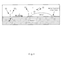
- FIG. 4 is a diagram illustrating a structure of an internal CO oxidation reaction of three-way catalytic.
- the total energy amount is increased or decreased according to increase or decrease of the loading (Metal Site) of precious metal of the catalyst 120.
- the controller 160 of the vehicle catalyst operating system 100 may apply the measured loading of the precious metal to the energy calculation method of oxidation reaction as shown in FIG. 3 such that the internal temperature of the catalyst can be calculated through a real-time calculation. That is, the controller 160 may calculate a calorific value of catalyst according to a detected loading of precious metal. In addition, the controller 160 may calculate the internal temperature of catalyst by applying the calculated calorific value of catalyst to the temperature modeling corresponding to the heat data of catalyst previously defined according to the air intake and the engine speed.
- the vehicle catalyst operating system 100 of the present invention configures the heat energy data of catalyst by reflecting a reference catalyst, a reference engine speed, a dependent variable data of intake flow rate, and a variable data of heat change due to the loading of precious metal catalyst.
- vehicle catalyst operating system 100 may digitize the calorific value of catalyst according to the change of loading of precious metal as an experimental data with respect to various reference catalysts to store in advance.
- the vehicle catalyst operating system 100 may previously store the temperature modeling corresponding to the heat data of catalyst based on the data for the air intake, the engine speed, and the calorific value of catalyst according to the change of loading of precious metal.
- the vehicle catalyst operating system 100 may detect a corresponding value of internal temperature of catalyst with reference to a corresponding reference data based on the air intake at the time of detection, the engine speed, and the element of loading of precious metal.
- FIG. 5 is a diagram illustrating an actual measurement temperature difference of catalyst according to a change of loading of precious metal catalyst
- FIG. 6 is a diagram illustrating a suitability of predicted temperature due to a change of heat generation data according to loading of precious metal catalyst.
- the measured temperature of the catalyst 120 may be changed in response to the engine speed according to the change of the loading of the precious metal. Consequently, if the element for the change of loading of precious metal is applied to the temperature change of catalyst 120, temperature can be detected more precisely.
- the present invention dependently reflects a heat generation due to an oxidation reaction occurred in the inside of the catalyst to the loading of the catalyst such that the inner temperature of the catalyst can be predicted more precisely.
- the present invention applies the variation of the inner temperature of the catalyst according to a change of catalyst which is not applied in the previous detection of temperature of the catalyst, such that the inner temperature of the catalyst differentiated in a plurality of vehicles having the same engine can be predicted precisely.
- a development period of engine and vehicle can be shortened, and a quality problem due to a catalyst temperature prediction error can be prevented in advance.
- the present invention precisely predicts the catalyst temperature such that a deterioration of fuel efficiency due to a reflection of unnecessary catalyst protection logic can be prevented.
Landscapes
- Engineering & Computer Science (AREA)
- Chemical & Material Sciences (AREA)
- Chemical Kinetics & Catalysis (AREA)
- Combustion & Propulsion (AREA)
- Mechanical Engineering (AREA)
- General Engineering & Computer Science (AREA)
- Analytical Chemistry (AREA)
- Health & Medical Sciences (AREA)
- Biomedical Technology (AREA)
- Environmental & Geological Engineering (AREA)
- General Chemical & Material Sciences (AREA)
- Oil, Petroleum & Natural Gas (AREA)
- Toxicology (AREA)
- Exhaust Gas After Treatment (AREA)
- Combined Controls Of Internal Combustion Engines (AREA)
- Exhaust Gas Treatment By Means Of Catalyst (AREA)
Abstract
Description
- The present application claims the benefit of priority to Korean Patent Application No.
10-2013-0127119, filed on October 24, 2013 - The present invention relates to a catalyst of a vehicle, and more particularly, to a system and a method for operating a catalyst of a vehicle that supports an improved prediction of exothermic energy of vehicle catalyst and a corresponding treatment.
- A vehicle is equipped with a catalytic converter for a treatment of exhaust gas of an engine. Typically, the vehicle controls an amount of fuel with a rich/lean state. The catalyst is capable of storing oxygen, and deoxidizes the exhaust gas to discharge water. The catalyst may be degraded by a variety of conditions. When the catalyst is degraded, an oxygen storage capacity (OSC) is reduced and a noise is generated. Furthermore, in severe cases, vehicle propulsion can be affected. In the meantime, the catalyst is influenced by a certain high-temperature environment. For example, when the catalyst is exposed to above an appropriate temperature, the durability of the catalyst may be deteriorated and, furthermore, may be damaged. To prevent this, in a related art, a variety of methods to detect a temperature of the catalyst have been proposed. For example, a conventional catalyst temperature measurement method is based on an air intake and an engine speed. However, according to such a method, the catalyst temperature is measured by an external factor regardless of the temperature measurement for a catalyst itself. Accordingly, the reliability of the detection results is low.
- Various aspects of the present invention are directed to providing a system and a method for operating a catalyst of a vehicle that supports to measure an internal temperature of the catalyst more minutely and accurately.
- In accordance with an aspect of the present invention, a system for operating a catalyst of a vehicle may include the catalyst configured to purify an exhaust gas of an engine, and a controller configured to perform a detection of internal temperature of the catalyst, wherein the controller detects the internal temperature of the catalyst by applying a change of precious metal loading of the catalyst to an internal temperature model of the catalyst.
- The system may further include a loading sensor to detect the change of the precious metal loading of the catalyst.
- The controller detects the internal temperature of the catalyst by applying a caloric value of the catalyst according to the change of the precious metal loading to a temperature modeling of the catalyst which is previously stored based on an air intake of the vehicle and a speed of the engine.
- The controller detects the internal temperature of the catalyst from a temperature modeling data corresponding to the air intake, the speed of the engine, and the caloric value of the catalyst which is previously determined according to the change of the precious metal loading of the catalyst.
- The controller adjusts an equivalence ratio when the internal temperature of the catalyst is a predefined certain temperature or more.
- In another aspect of the present invention, a method for a system for operating a catalyst of a vehicle may include detecting an air intake of an engine of the vehicle, an engine speed, and a precious metal loading of the catalyst, and determining an internal temperature of the catalyst by applying a caloric value of catalyst according to a change of the precious metal loading to a catalyst heat data which is previously stored based on the air intake of the vehicle and the engine speed.
- The method may further include adjusting an equivalence ratio when the internal temperature of the catalyst is a predefined certain temperature or more.
- The system for operating the catalyst may include the catalyst configured to purify an exhaust gas of the engine, and a controller configured to perform detection of the internal temperature of the catalyst, wherein the controller detects the internal temperature of the catalyst by applying the change of the precious metal loading of the catalyst to an internal temperature model of the catalyst.
- The system for operating the catalyst may further include a loading sensor to detect the change of the precious metal loading of the catalyst.
- In further another aspect of the present invention, a method for operating a catalyst of a vehicle, may include storing a catalyst heat data corresponding to an internal temperature of the catalyst built based on an air intake of an engine of the vehicle, an engine speed, and a caloric value of the catalyst corresponding to a precious metal loading of the catalyst, and determining an internal temperature of the catalyst in response to the detected value based on the catalyst heat data.
- The method may further include adjusting an equivalence ratio when the internal temperature of the catalyst is a predefined certain temperature or more.
- The system for operating the catalyst may include the catalyst configured to purify an exhaust gas of the engine, and a controller configured to perform detection of the internal temperature of the catalyst, wherein the controller detects the internal temperature of the catalyst by applying a change of the precious metal loading of the catalyst to an internal temperature model of the catalyst.
- The system for operating the catalyst may further include a loading sensor to detect the change of the precious metal loading of the catalyst.
- The methods and apparatuses of the present invention have other features and advantages which will be apparent from or are set forth in more detail in the accompanying drawings, which are incorporated herein, and the following Detailed Description, which together serve to explain certain principles of the present invention.
-
-
FIG. 1 is a block diagram illustrating a schematic configuration of a vehiclecatalyst operating system 100 according to an exemplary embodiment of the present invention. -
FIG. 2 is a flowchart illustrating a vehicle catalyst operating method according to an exemplary embodiment of the present invention. -
FIG. 3 is a diagram illustrating a heat emission quantity according to an internal oxidation reaction of a catalyst according to an exemplary embodiment of the present invention. -
FIG. 4 is a diagram illustrating a structure of an internal CO oxidation reaction of three-way catalytic. -
FIG. 5 is a diagram illustrating an actual measurement temperature difference of catalyst according to a change of loading of precious metal catalyst. -
FIG. 6 is a diagram illustrating a suitability of predicted temperature due to a change of heat generation data according to loading of precious metal catalyst. - It should be understood that the appended drawings are not necessarily to scale, presenting a somewhat simplified representation of various features illustrative of the basic principles of the invention. The specific design features of the present invention as disclosed herein, including, for example, specific dimensions, orientations, locations, and shapes will be determined in part by the particular intended application and use environment.
- In the figures, reference numbers refer to the same or equivalent parts of the present invention throughout the several figures of the drawing.
- Reference will now be made in detail to various embodiments of the present invention(s), examples of which are illustrated in the accompanying drawings and described below. While the invention(s) will be described in conjunction with exemplary embodiments, it will be understood that the present description is not intended to limit the invention(s) to those exemplary embodiments. On the contrary, the invention(s) is/are intended to cover not only the exemplary embodiments, but also various alternatives, modifications, equivalents and other embodiments, which may be included within the spirit and scope of the invention as defined by the appended claims.
- Exemplary embodiments of the present invention are described with reference to the accompanying drawings in detail. The same reference numbers are used throughout the drawings to refer to the same or like parts. Detailed descriptions of well-known functions and structures incorporated herein may be omitted to avoid obscuring the subject matter of the present invention.
-
FIG. 1 is a block diagram illustrating a schematic configuration of a vehiclecatalyst operating system 100 according to an exemplary embodiment of the present invention. - Referring to
FIG. 1 , the vehiclecatalyst operating system 100 of the present invention includes anengine 110, acatalyst 120, anexhaust port 130, aloading sensor 150, and acontroller 160. Additionally, the vehiclecatalyst operating system 100 may further include arear oxygen sensor 140. - Such a configuration of the vehicle
catalyst operating system 100 may calculate an internal temperature ofcatalyst 120 by using an exhaust gas flow rate, an exhaust gas temperature, an exhaust gas component, and the loading amount of precious metal catalyst obtained through theloading sensor 150. The vehiclecatalyst operating system 100 may operate protection logic to protect the catalyst based on the obtained internal temperature of the catalyst. - When the protection logic is operated, the vehicle
catalyst operating system 100 may adjust a concentration of equivalence ratio to reduce the catalyst temperature. This enables the vehiclecatalyst operating system 100 of the present invention to reduce the catalyst temperature by suppressing the oxidation generated in the inside of the catalyst. The above-described vehiclecatalyst operating system 100 reflects the change of internal oxidation reaction to a control model according to an amount of the precious metal catalyst deposited in the inside of thecatalyst 120 to determine the internal catalyst temperature. Based on this model, the vehiclecatalyst operating system 100 of the present invention may accurately predict the internal temperature of thecatalyst 120 having different characteristics for each regulation in the same engine. In addition, the vehiclecatalyst operating system 100 of the present invention may prevent the adjustment of unnecessary rich condition in a high speed region. - The
engine 110 is a configuration to burn the injected fuel to generate a power. Theengine 110 may be operated in a constant speed according to a control of a motor controller, e.g., thecontroller 160. The engine speed may be feedback again to thecontroller 160. Theengine 110 may discharge an exhaust gas due to the fuel combustion to theexhaust port 130 through thecatalyst 120. - The
catalyst 120 is disposed between theengine 110 and theexhaust port 130 to perform a purification of exhaust gas discharged from theengine 110. Thiscatalyst 120 may be configured with various types to purify exhaust gas. In particular, the catalysts of thepresent invention 120 may include precious metals such as palladium, rhodium, platinum, cerium, and the like for a three-way catalytic oxidation reaction. The loading of the precious metal included in thecatalyst 120 may be changed. The change of the loading of the precious metal in thecatalyst 120 may be sensed by theloading sensor 150. - The
exhaust port 130 is disposed at the rear end of thecatalyst 120 to discharge a material discharged from thecatalyst 120. Such anexhaust port 130 guides the exhaust gas output from thecatalyst 120. Therear oxygen sensor 140 may be disposed at one side of theexhaust port 130. - The
loading sensor 150 is a sensor that detects the change of the precious metal loading in thecatalyst 120. - The
rear oxygen sensor 140 is disposed at the outlet side of thecatalyst 120, and detects the oxygen concentration which is switched according to rich/lean of a mixing ratio to thecontroller 160. Therear oxygen sensor 140 adds up the exhaust gas discharged through theexhaust port 130 to detect the deterioration of the catalyst. - Since a heat loss is slightly generated when the exhaust gas burnt in the
engine 110 is supplied to thecatalyst 120 through an exhaust pipe, it may be determined that the inlet temperature of thecatalyst 120 is identical with the discharge temperature of theengine 110. Consequently, thecontroller 160 may determine the exhaust gas modeling temperature of thecatalyst 120 according to an engine speed and an air intake. - In particular, the
controller 160 additionally performs a modeling of an internal temperature change of catalyst according to a catalyst loading with respect to a basic logic that performs a modeling of temperature of each part from the exhaust port of theengine 110 to the rear end of thecatalyst 120 by modeling a thermodynamics of an exhaust system, such that the internal temperature change of catalyst according to a change of catalyst loading can be predicted accurately. The temperature due to the heat generated in the catalyst may be determined by the exhaust gas flow rate, the exhaust gas temperature, the exhaust gas component, and the oxidation reaction generated in the precious metal in the inside of the catalyst. The quantity of heat of exhaust gas which is latent in the exhaust gas may be determined by an exhaust flow rate and a heat capacity of the exhaust gas. - That is, the internal temperature of catalyst may be determined according to the quantity of heat of exhaust gas and the oxidation reaction of precious metal loading deposited in the catalyst. Meanwhile, the
controller 160 may perform a modeling of temperature generated in the inside of the catalyst based on a convective heat transfer. That is, thecontroller 160 may calculate the internal temperature of catalyst as described in a followingEquation 1 by using the quantity of heat of exhaust gas and the oxidation reaction energy generated in the precious metal in the inside of the catalyst.
- Here, Tcat is an internal temperature of a catalyst, Q is an internal oxidation reaction energy of a catalytic, m^ is an exhaust gas flow rate, Cp is a heat capacity of an exhaust gas. The internal oxidation reaction energy Q of a catalyst is changed depending on the precious metal loading deposited in the
catalyst 120. Thus, thecontroller 160 configures a dependent variable data of precious metal loading of thecatalyst 120 with the internal oxidation reaction energy Q of a catalyst to reflect the change of internal temperature of catalyst due to loading of the precious metal. - As described above, the vehicle
catalyst operating system 100 of the present invention may apply the change of precious metal loading ofcatalyst 120 to calculate the quantity of heat according to the internal oxidation reaction of thecatalyst 120 such that the catalyst temperature can be measured more accurately. -
FIG. 2 is a flowchart illustrating a vehicle catalyst operating method according to an exemplary embodiment of the present invention. - Referring to
FIG. 2 , in the vehicle catalyst operating method of the present invention, thecontroller 160 detects the loading of precious metal ofcatalyst 120 in step S101. To this end, thecontroller 160 may activate theloading sensor 150, and detect the loading of the precious metal of thecatalyst 120 at the present point by using theloading sensor 150. - Next, the
controller 160 may calculate the internal temperature of the catalyst in step S103. In this process, thecontroller 160 may apply the change value of the loading of precious metal to the temperature modeling provided by using the air intake and the engine speed. Thecontroller 160 may previously store a data of temperature modeling corresponding to a heat generation data of the catalyst calculated in response to the change of the air intake and the engine speed. The temperature modeling corresponding to the heat generation data of the catalyst in response to the change of the air intake and the engine speed may be provided based on a variety of experiments. - Next, the
controller 160 may determine whether catalyst protection logic is reflected in step S105. That is, thecontroller 160 may determine whether the current internal temperature of the catalyst is a predefined certain temperature or more. When the internal temperature of the catalyst is a predefined certain temperature or more in step S105, thecontroller 160 may perform an environment control in accordance with protection logic in step S107. For example, thecontroller 160 may perform the adjustment of equivalence ratio to reduce the temperature of thecatalyst 120. In the meantime, when the internal temperature of the catalytic is below a predefined certain temperature in step S105, thecontroller 160 may control to skip the step S107. -
FIG. 3 is a diagram illustrating a heat emission quantity according to an internal oxidation reaction of a catalyst according to an exemplary embodiment of the present invention, andFIG. 4 is a diagram illustrating a structure of an internal CO oxidation reaction of three-way catalytic. - Referring to
FIG. 3 andFIG. 4 , in the heat emission quantity according to an internal chemical oxidation reaction in the inside of thecatalyst 120, the total energy amount is increased or decreased according to increase or decrease of the loading (Metal Site) of precious metal of thecatalyst 120. - This is reflected to the internal temperature modeling with a dependent function of precious metal content such that the accuracy of prediction of internal temperature of the catalyst may be increased by using the difference of the emission quantity of heat energy according to the change of precious metal loading of catalyst.
- The
controller 160 of the vehiclecatalyst operating system 100 may apply the measured loading of the precious metal to the energy calculation method of oxidation reaction as shown inFIG. 3 such that the internal temperature of the catalyst can be calculated through a real-time calculation. That is, thecontroller 160 may calculate a calorific value of catalyst according to a detected loading of precious metal. In addition, thecontroller 160 may calculate the internal temperature of catalyst by applying the calculated calorific value of catalyst to the temperature modeling corresponding to the heat data of catalyst previously defined according to the air intake and the engine speed. - The vehicle
catalyst operating system 100 of the present invention configures the heat energy data of catalyst by reflecting a reference catalyst, a reference engine speed, a dependent variable data of intake flow rate, and a variable data of heat change due to the loading of precious metal catalyst. Here, vehiclecatalyst operating system 100 may digitize the calorific value of catalyst according to the change of loading of precious metal as an experimental data with respect to various reference catalysts to store in advance. - That is, the vehicle
catalyst operating system 100 may previously store the temperature modeling corresponding to the heat data of catalyst based on the data for the air intake, the engine speed, and the calorific value of catalyst according to the change of loading of precious metal. In addition, the vehiclecatalyst operating system 100 may detect a corresponding value of internal temperature of catalyst with reference to a corresponding reference data based on the air intake at the time of detection, the engine speed, and the element of loading of precious metal. -
FIG. 5 is a diagram illustrating an actual measurement temperature difference of catalyst according to a change of loading of precious metal catalyst, andFIG. 6 is a diagram illustrating a suitability of predicted temperature due to a change of heat generation data according to loading of precious metal catalyst. - Referring to
FIG. 5 andFIG. 6 , the measured temperature of thecatalyst 120 may be changed in response to the engine speed according to the change of the loading of the precious metal. Consequently, if the element for the change of loading of precious metal is applied to the temperature change ofcatalyst 120, temperature can be detected more precisely. - Thus, the present invention dependently reflects a heat generation due to an oxidation reaction occurred in the inside of the catalyst to the loading of the catalyst such that the inner temperature of the catalyst can be predicted more precisely.
- In addition, the present invention applies the variation of the inner temperature of the catalyst according to a change of catalyst which is not applied in the previous detection of temperature of the catalyst, such that the inner temperature of the catalyst differentiated in a plurality of vehicles having the same engine can be predicted precisely.
- In addition, according to an exemplary embodiment of the present invention, a development period of engine and vehicle can be shortened, and a quality problem due to a catalyst temperature prediction error can be prevented in advance.
- In addition, the present invention precisely predicts the catalyst temperature such that a deterioration of fuel efficiency due to a reflection of unnecessary catalyst protection logic can be prevented.
- The foregoing descriptions of specific exemplary embodiments of the present invention have been presented for purposes of illustration and description. They are not intended to be exhaustive or to limit the invention to the precise forms disclosed, and obviously many modifications and variations are possible in light of the above teachings. The exemplary embodiments were chosen and described in order to explain certain prin120es of the invention and their practical application, to thereby enable others skilled in the art to make and utilize various exemplary embodiments of the present invention, as well as various alternatives and modifications thereof. It is intended that the scope of the invention be defined by the Claims appended hereto and their equivalents.
-
- 100: THE VEHICLE CATALYST OPERATING SYSTEM
- 110: ENGINE
- 120: CATALYST
- 130: EXHAUST PORT
- 140: OXYGEN SENSOR
- 150: LOADING SENSOR
- 160: CONTROLLER
Claims (13)
- A system for operating a catalyst of a vehicle, the system comprising:the catalyst configured to purify an exhaust gas of an engine; anda controller configured to perform a detection of internal temperature of the catalyst,wherein the controller detects the internal temperature of the catalyst by applying a change of precious metal loading of the catalyst to an internal temperature model of the catalyst.
- The system of claim 1, further comprising a loading sensor to detect the change of the precious metal loading of the catalyst.
- The system of claim 2, wherein the controller detects the internal temperature of the catalyst by applying a caloric value of the catalyst according to the change of the precious metal loading to a temperature modeling of the catalyst which is previously stored based on an air intake of the vehicle and a speed of the engine.
- The system of claim 2, wherein the controller detects the internal temperature of the catalyst from a temperature modeling data corresponding to the air intake, the speed of the engine, and the caloric value of the catalyst which is previously determined according to the change of the precious metal loading of the catalyst.
- The system of claim 1, wherein the controller adjusts an equivalence ratio when the internal temperature of the catalyst is a predefined certain temperature or more.
- A method for a system for operating a catalyst of a vehicle, the method comprising:detecting an air intake of an engine of the vehicle, an engine speed, and a precious metal loading of the catalyst; anddetermining an internal temperature of the catalyst by applying a caloric value of catalyst according to a change of the precious metal loading to a catalyst heat data which is previously stored based on the air intake of the vehicle and the engine speed.
- The method of claim 6, further comprising adjusting an equivalence ratio when the internal temperature of the catalyst is a predefined certain temperature or more.
- The method of claim 6, wherein the system for operating the catalyst includes:the catalyst configured to purify an exhaust gas of the engine; anda controller configured to perform detection of the internal temperature of the catalyst,wherein the controller detects the internal temperature of the catalyst by applying the change of the precious metal loading of the catalyst to an internal temperature model of the catalyst.
- The method of claim 6, wherein the system for operating the catalyst further includes a loading sensor to detect the change of the precious metal loading of the catalyst.
- A method for operating a catalyst of a vehicle, the method comprising:storing a catalyst heat data corresponding to an internal temperature of the catalyst built based on an air intake of an engine of the vehicle, an engine speed, and a caloric value of the catalyst corresponding to a precious metal loading of the catalyst; anddetermining an internal temperature of the catalyst in response to the detected value based on the catalyst heat data.
- The method of claim 10, further comprising adjusting an equivalence ratio when the internal temperature of the catalyst is a predefined certain temperature or more.
- The method of claim 10, wherein the system for operating the catalyst includes:the catalyst configured to purify an exhaust gas of the engine; anda controller configured to perform detection of the internal temperature of the catalyst,wherein the controller detects the internal temperature of the catalyst by applying a change of the precious metal loading of the catalyst to an internal temperature model of the catalyst.
- The method of claim 10, wherein the system for operating the catalyst further includes a loading sensor to detect the change of the precious metal loading of the catalyst.
Applications Claiming Priority (1)
| Application Number | Priority Date | Filing Date | Title |
|---|---|---|---|
| KR1020130127119A KR101534933B1 (en) | 2013-10-24 | 2013-10-24 | Operating System for Catalyst of Vehicle and Method thereof |
Publications (2)
| Publication Number | Publication Date |
|---|---|
| EP2865862A1 true EP2865862A1 (en) | 2015-04-29 |
| EP2865862B1 EP2865862B1 (en) | 2017-06-14 |
Family
ID=51494152
Family Applications (1)
| Application Number | Title | Priority Date | Filing Date |
|---|---|---|---|
| EP14184015.7A Not-in-force EP2865862B1 (en) | 2013-10-24 | 2014-09-09 | Operating system for catalyst of vehicle and method thereof |
Country Status (4)
| Country | Link |
|---|---|
| US (1) | US20150113954A1 (en) |
| EP (1) | EP2865862B1 (en) |
| KR (1) | KR101534933B1 (en) |
| CN (1) | CN104564261A (en) |
Families Citing this family (2)
| Publication number | Priority date | Publication date | Assignee | Title |
|---|---|---|---|---|
| JP6520971B2 (en) * | 2017-03-02 | 2019-05-29 | トヨタ自動車株式会社 | Exhaust purification system for internal combustion engine |
| US10323561B2 (en) * | 2017-04-19 | 2019-06-18 | GM Global Technology Operations LLC | Methods for monitoring and modelling thermal characteristics of oxidation catalyst devices |
Citations (4)
| Publication number | Priority date | Publication date | Assignee | Title |
|---|---|---|---|---|
| DE102005015998A1 (en) * | 2005-04-07 | 2006-10-12 | Robert Bosch Gmbh | Catalyst diagnostic procedures |
| DE102007044863A1 (en) * | 2007-09-20 | 2009-04-23 | Continental Automotive Gmbh | Catalytic converter temperature modeling method for e.g. passenger car, involves determining catalytic converter temperature based on input variable and actual parameter, and modeling converter temperature based on determined temperature |
| US20100312451A1 (en) * | 2009-06-09 | 2010-12-09 | Ford Global Technologies, Llc | Modeling catalyst exotherm due to blowthrough |
| WO2011055176A1 (en) * | 2009-11-06 | 2011-05-12 | Toyota Jidosha Kabushiki Kaisha | Exhaust catalyst temperature estimating apparatus and exhaust catalyst temperature estimation method for internal combustion engine |
Family Cites Families (7)
| Publication number | Priority date | Publication date | Assignee | Title |
|---|---|---|---|---|
| US7363758B2 (en) * | 2004-11-09 | 2008-04-29 | Ford Global Technologies, Llc | Lean burn engine control NOx purging based on positional loading of oxidants in emission control device |
| EP1994982A1 (en) * | 2007-03-30 | 2008-11-26 | Fujifilm Corporation | Catalyst body which uses an anodized layer |
| KR100986071B1 (en) * | 2008-06-09 | 2010-10-07 | 현대자동차주식회사 | Vehicle Exhaust Gas Purification System and Control Method |
| KR100993369B1 (en) * | 2008-07-18 | 2010-11-09 | 현대자동차주식회사 | Vehicle catalyst diagnosis device and method |
| US8584445B2 (en) * | 2009-02-04 | 2013-11-19 | GM Global Technology Operations LLC | Method and system for controlling an electrically heated particulate filter |
| US7942043B2 (en) * | 2009-02-19 | 2011-05-17 | Detroit Diesel Corporation | On-board aftertreatment device tail pipe hydrocarbon slip calculation |
| JP2013044283A (en) * | 2011-08-24 | 2013-03-04 | Toyota Industries Corp | Exhaust gas purification catalyst |
-
2013
- 2013-10-24 KR KR1020130127119A patent/KR101534933B1/en not_active Expired - Fee Related
-
2014
- 2014-09-09 EP EP14184015.7A patent/EP2865862B1/en not_active Not-in-force
- 2014-09-17 US US14/489,142 patent/US20150113954A1/en not_active Abandoned
- 2014-09-29 CN CN201410515379.XA patent/CN104564261A/en active Pending
Patent Citations (4)
| Publication number | Priority date | Publication date | Assignee | Title |
|---|---|---|---|---|
| DE102005015998A1 (en) * | 2005-04-07 | 2006-10-12 | Robert Bosch Gmbh | Catalyst diagnostic procedures |
| DE102007044863A1 (en) * | 2007-09-20 | 2009-04-23 | Continental Automotive Gmbh | Catalytic converter temperature modeling method for e.g. passenger car, involves determining catalytic converter temperature based on input variable and actual parameter, and modeling converter temperature based on determined temperature |
| US20100312451A1 (en) * | 2009-06-09 | 2010-12-09 | Ford Global Technologies, Llc | Modeling catalyst exotherm due to blowthrough |
| WO2011055176A1 (en) * | 2009-11-06 | 2011-05-12 | Toyota Jidosha Kabushiki Kaisha | Exhaust catalyst temperature estimating apparatus and exhaust catalyst temperature estimation method for internal combustion engine |
Also Published As
| Publication number | Publication date |
|---|---|
| KR101534933B1 (en) | 2015-07-07 |
| EP2865862B1 (en) | 2017-06-14 |
| KR20150047260A (en) | 2015-05-04 |
| US20150113954A1 (en) | 2015-04-30 |
| CN104564261A (en) | 2015-04-29 |
Similar Documents
| Publication | Publication Date | Title |
|---|---|---|
| JP4645984B2 (en) | Deterioration detection device for exhaust gas sensor | |
| EP1411229B1 (en) | Air-fuel ratio controller of internal combustion engine | |
| US6990800B2 (en) | Diesel aftertreatment systems | |
| US6202406B1 (en) | Method and apparatus for catalyst temperature control | |
| JP4530081B2 (en) | Catalyst deterioration diagnosis apparatus and catalyst deterioration diagnosis method for internal combustion engine | |
| CN101790624B (en) | Method for checking the state of aging of a catalytic converter on a vehicle | |
| US6990854B2 (en) | Active lean NOx catalyst diagnostics | |
| US9181841B2 (en) | Method and apparatus for monitoring the light-off temperature of a diesel oxidation catalyst | |
| US9234474B2 (en) | Control oriented model for LNT regeneration | |
| US12436065B2 (en) | Method and device for measuring nitrogen oxide and ammonia emissions from an exhaust gas aftertreatment system for combustion exhaust gases | |
| CN110821619B (en) | Method and device for exhaust gas aftertreatment of an internal combustion engine | |
| US5822979A (en) | Catalyst monitoring using a hydrocarbon sensor | |
| CN102400753A (en) | Method for predicting exhaust gas temperature | |
| WO2010150408A1 (en) | Exhaust emission control system of internal combustion engine | |
| US20200182179A1 (en) | Three-way catalyst oxygen storage model | |
| EP2865862B1 (en) | Operating system for catalyst of vehicle and method thereof | |
| CN108150251A (en) | Waste gas purification apparatus and its control method | |
| EP2496802A1 (en) | Exhaust catalyst temperature estimating apparatus and exhaust catalyst temperature estimation method for internal combustion engine | |
| JP2005090479A (en) | Engine exhaust gas temperature predicting method | |
| KR100993369B1 (en) | Vehicle catalyst diagnosis device and method | |
| CN105604662A (en) | Method and control device for operating internal combustion engine | |
| CN117365715A (en) | Method and calculation unit for determining the filling level of an exhaust gas catalytic converter | |
| Piqueras et al. | Potential of H2-Assisted Light-Off of Oxidation Catalyst in H2-Diesel Dual-Fuel Engines | |
| US11384674B2 (en) | Reuse evaluation system for catalyst | |
| JP2006077738A (en) | Catalyst deterioration detection device for internal combustion engine |
Legal Events
| Date | Code | Title | Description |
|---|---|---|---|
| PUAI | Public reference made under article 153(3) epc to a published international application that has entered the european phase |
Free format text: ORIGINAL CODE: 0009012 |
|
| 17P | Request for examination filed |
Effective date: 20140909 |
|
| AK | Designated contracting states |
Kind code of ref document: A1 Designated state(s): AL AT BE BG CH CY CZ DE DK EE ES FI FR GB GR HR HU IE IS IT LI LT LU LV MC MK MT NL NO PL PT RO RS SE SI SK SM TR |
|
| AX | Request for extension of the european patent |
Extension state: BA ME |
|
| R17P | Request for examination filed (corrected) |
Effective date: 20150723 |
|
| RBV | Designated contracting states (corrected) |
Designated state(s): AL AT BE BG CH CY CZ DE DK EE ES FI FR GB GR HR HU IE IS IT LI LT LU LV MC MK MT NL NO PL PT RO RS SE SI SK SM TR |
|
| GRAP | Despatch of communication of intention to grant a patent |
Free format text: ORIGINAL CODE: EPIDOSNIGR1 |
|
| RIC1 | Information provided on ipc code assigned before grant |
Ipc: F01N 9/00 20060101AFI20161221BHEP Ipc: F01N 11/00 20060101ALI20161221BHEP |
|
| INTG | Intention to grant announced |
Effective date: 20170113 |
|
| RIN1 | Information on inventor provided before grant (corrected) |
Inventor name: MOK, JONG SOO |
|
| GRAS | Grant fee paid |
Free format text: ORIGINAL CODE: EPIDOSNIGR3 |
|
| GRAA | (expected) grant |
Free format text: ORIGINAL CODE: 0009210 |
|
| AK | Designated contracting states |
Kind code of ref document: B1 Designated state(s): AL AT BE BG CH CY CZ DE DK EE ES FI FR GB GR HR HU IE IS IT LI LT LU LV MC MK MT NL NO PL PT RO RS SE SI SK SM TR |
|
| REG | Reference to a national code |
Ref country code: GB Ref legal event code: FG4D |
|
| REG | Reference to a national code |
Ref country code: CH Ref legal event code: EP Ref country code: AT Ref legal event code: REF Ref document number: 901195 Country of ref document: AT Kind code of ref document: T Effective date: 20170615 |
|
| REG | Reference to a national code |
Ref country code: IE Ref legal event code: FG4D |
|
| REG | Reference to a national code |
Ref country code: DE Ref legal event code: R096 Ref document number: 602014010690 Country of ref document: DE |
|
| REG | Reference to a national code |
Ref country code: NL Ref legal event code: MP Effective date: 20170614 |
|
| REG | Reference to a national code |
Ref country code: LT Ref legal event code: MG4D |
|
| PG25 | Lapsed in a contracting state [announced via postgrant information from national office to epo] |
Ref country code: LT Free format text: LAPSE BECAUSE OF FAILURE TO SUBMIT A TRANSLATION OF THE DESCRIPTION OR TO PAY THE FEE WITHIN THE PRESCRIBED TIME-LIMIT Effective date: 20170614 Ref country code: GR Free format text: LAPSE BECAUSE OF FAILURE TO SUBMIT A TRANSLATION OF THE DESCRIPTION OR TO PAY THE FEE WITHIN THE PRESCRIBED TIME-LIMIT Effective date: 20170915 Ref country code: NO Free format text: LAPSE BECAUSE OF FAILURE TO SUBMIT A TRANSLATION OF THE DESCRIPTION OR TO PAY THE FEE WITHIN THE PRESCRIBED TIME-LIMIT Effective date: 20170914 Ref country code: FI Free format text: LAPSE BECAUSE OF FAILURE TO SUBMIT A TRANSLATION OF THE DESCRIPTION OR TO PAY THE FEE WITHIN THE PRESCRIBED TIME-LIMIT Effective date: 20170614 Ref country code: HR Free format text: LAPSE BECAUSE OF FAILURE TO SUBMIT A TRANSLATION OF THE DESCRIPTION OR TO PAY THE FEE WITHIN THE PRESCRIBED TIME-LIMIT Effective date: 20170614 |
|
| PGFP | Annual fee paid to national office [announced via postgrant information from national office to epo] |
Ref country code: DE Payment date: 20170822 Year of fee payment: 4 |
|
| REG | Reference to a national code |
Ref country code: AT Ref legal event code: MK05 Ref document number: 901195 Country of ref document: AT Kind code of ref document: T Effective date: 20170614 |
|
| PG25 | Lapsed in a contracting state [announced via postgrant information from national office to epo] |
Ref country code: RS Free format text: LAPSE BECAUSE OF FAILURE TO SUBMIT A TRANSLATION OF THE DESCRIPTION OR TO PAY THE FEE WITHIN THE PRESCRIBED TIME-LIMIT Effective date: 20170614 Ref country code: NL Free format text: LAPSE BECAUSE OF FAILURE TO SUBMIT A TRANSLATION OF THE DESCRIPTION OR TO PAY THE FEE WITHIN THE PRESCRIBED TIME-LIMIT Effective date: 20170614 Ref country code: LV Free format text: LAPSE BECAUSE OF FAILURE TO SUBMIT A TRANSLATION OF THE DESCRIPTION OR TO PAY THE FEE WITHIN THE PRESCRIBED TIME-LIMIT Effective date: 20170614 Ref country code: SE Free format text: LAPSE BECAUSE OF FAILURE TO SUBMIT A TRANSLATION OF THE DESCRIPTION OR TO PAY THE FEE WITHIN THE PRESCRIBED TIME-LIMIT Effective date: 20170614 Ref country code: BG Free format text: LAPSE BECAUSE OF FAILURE TO SUBMIT A TRANSLATION OF THE DESCRIPTION OR TO PAY THE FEE WITHIN THE PRESCRIBED TIME-LIMIT Effective date: 20170914 |
|
| PG25 | Lapsed in a contracting state [announced via postgrant information from national office to epo] |
Ref country code: AT Free format text: LAPSE BECAUSE OF FAILURE TO SUBMIT A TRANSLATION OF THE DESCRIPTION OR TO PAY THE FEE WITHIN THE PRESCRIBED TIME-LIMIT Effective date: 20170614 Ref country code: EE Free format text: LAPSE BECAUSE OF FAILURE TO SUBMIT A TRANSLATION OF THE DESCRIPTION OR TO PAY THE FEE WITHIN THE PRESCRIBED TIME-LIMIT Effective date: 20170614 Ref country code: CZ Free format text: LAPSE BECAUSE OF FAILURE TO SUBMIT A TRANSLATION OF THE DESCRIPTION OR TO PAY THE FEE WITHIN THE PRESCRIBED TIME-LIMIT Effective date: 20170614 Ref country code: SK Free format text: LAPSE BECAUSE OF FAILURE TO SUBMIT A TRANSLATION OF THE DESCRIPTION OR TO PAY THE FEE WITHIN THE PRESCRIBED TIME-LIMIT Effective date: 20170614 Ref country code: RO Free format text: LAPSE BECAUSE OF FAILURE TO SUBMIT A TRANSLATION OF THE DESCRIPTION OR TO PAY THE FEE WITHIN THE PRESCRIBED TIME-LIMIT Effective date: 20170614 |
|
| PG25 | Lapsed in a contracting state [announced via postgrant information from national office to epo] |
Ref country code: IT Free format text: LAPSE BECAUSE OF FAILURE TO SUBMIT A TRANSLATION OF THE DESCRIPTION OR TO PAY THE FEE WITHIN THE PRESCRIBED TIME-LIMIT Effective date: 20170614 Ref country code: ES Free format text: LAPSE BECAUSE OF FAILURE TO SUBMIT A TRANSLATION OF THE DESCRIPTION OR TO PAY THE FEE WITHIN THE PRESCRIBED TIME-LIMIT Effective date: 20170614 Ref country code: PL Free format text: LAPSE BECAUSE OF FAILURE TO SUBMIT A TRANSLATION OF THE DESCRIPTION OR TO PAY THE FEE WITHIN THE PRESCRIBED TIME-LIMIT Effective date: 20170614 Ref country code: SM Free format text: LAPSE BECAUSE OF FAILURE TO SUBMIT A TRANSLATION OF THE DESCRIPTION OR TO PAY THE FEE WITHIN THE PRESCRIBED TIME-LIMIT Effective date: 20170614 Ref country code: IS Free format text: LAPSE BECAUSE OF FAILURE TO SUBMIT A TRANSLATION OF THE DESCRIPTION OR TO PAY THE FEE WITHIN THE PRESCRIBED TIME-LIMIT Effective date: 20171014 |
|
| REG | Reference to a national code |
Ref country code: DE Ref legal event code: R097 Ref document number: 602014010690 Country of ref document: DE |
|
| PLBE | No opposition filed within time limit |
Free format text: ORIGINAL CODE: 0009261 |
|
| STAA | Information on the status of an ep patent application or granted ep patent |
Free format text: STATUS: NO OPPOSITION FILED WITHIN TIME LIMIT |
|
| PG25 | Lapsed in a contracting state [announced via postgrant information from national office to epo] |
Ref country code: DK Free format text: LAPSE BECAUSE OF FAILURE TO SUBMIT A TRANSLATION OF THE DESCRIPTION OR TO PAY THE FEE WITHIN THE PRESCRIBED TIME-LIMIT Effective date: 20170614 |
|
| REG | Reference to a national code |
Ref country code: CH Ref legal event code: PL |
|
| 26N | No opposition filed |
Effective date: 20180315 |
|
| PG25 | Lapsed in a contracting state [announced via postgrant information from national office to epo] |
Ref country code: MC Free format text: LAPSE BECAUSE OF FAILURE TO SUBMIT A TRANSLATION OF THE DESCRIPTION OR TO PAY THE FEE WITHIN THE PRESCRIBED TIME-LIMIT Effective date: 20170614 |
|
| REG | Reference to a national code |
Ref country code: IE Ref legal event code: MM4A |
|
| REG | Reference to a national code |
Ref country code: BE Ref legal event code: MM Effective date: 20170930 |
|
| PG25 | Lapsed in a contracting state [announced via postgrant information from national office to epo] |
Ref country code: LU Free format text: LAPSE BECAUSE OF NON-PAYMENT OF DUE FEES Effective date: 20170909 |
|
| REG | Reference to a national code |
Ref country code: FR Ref legal event code: ST Effective date: 20180531 |
|
| PG25 | Lapsed in a contracting state [announced via postgrant information from national office to epo] |
Ref country code: CH Free format text: LAPSE BECAUSE OF NON-PAYMENT OF DUE FEES Effective date: 20170930 Ref country code: LI Free format text: LAPSE BECAUSE OF NON-PAYMENT OF DUE FEES Effective date: 20170930 Ref country code: IE Free format text: LAPSE BECAUSE OF NON-PAYMENT OF DUE FEES Effective date: 20170909 |
|
| PG25 | Lapsed in a contracting state [announced via postgrant information from national office to epo] |
Ref country code: FR Free format text: LAPSE BECAUSE OF NON-PAYMENT OF DUE FEES Effective date: 20171002 Ref country code: BE Free format text: LAPSE BECAUSE OF NON-PAYMENT OF DUE FEES Effective date: 20170930 Ref country code: SI Free format text: LAPSE BECAUSE OF FAILURE TO SUBMIT A TRANSLATION OF THE DESCRIPTION OR TO PAY THE FEE WITHIN THE PRESCRIBED TIME-LIMIT Effective date: 20170614 |
|
| PG25 | Lapsed in a contracting state [announced via postgrant information from national office to epo] |
Ref country code: MT Free format text: LAPSE BECAUSE OF NON-PAYMENT OF DUE FEES Effective date: 20170909 |
|
| REG | Reference to a national code |
Ref country code: DE Ref legal event code: R119 Ref document number: 602014010690 Country of ref document: DE |
|
| GBPC | Gb: european patent ceased through non-payment of renewal fee |
Effective date: 20180909 |
|
| PG25 | Lapsed in a contracting state [announced via postgrant information from national office to epo] |
Ref country code: HU Free format text: LAPSE BECAUSE OF FAILURE TO SUBMIT A TRANSLATION OF THE DESCRIPTION OR TO PAY THE FEE WITHIN THE PRESCRIBED TIME-LIMIT; INVALID AB INITIO Effective date: 20140909 |
|
| PG25 | Lapsed in a contracting state [announced via postgrant information from national office to epo] |
Ref country code: DE Free format text: LAPSE BECAUSE OF NON-PAYMENT OF DUE FEES Effective date: 20190402 |
|
| PG25 | Lapsed in a contracting state [announced via postgrant information from national office to epo] |
Ref country code: GB Free format text: LAPSE BECAUSE OF NON-PAYMENT OF DUE FEES Effective date: 20180909 Ref country code: CY Free format text: LAPSE BECAUSE OF FAILURE TO SUBMIT A TRANSLATION OF THE DESCRIPTION OR TO PAY THE FEE WITHIN THE PRESCRIBED TIME-LIMIT Effective date: 20170614 |
|
| PG25 | Lapsed in a contracting state [announced via postgrant information from national office to epo] |
Ref country code: MK Free format text: LAPSE BECAUSE OF FAILURE TO SUBMIT A TRANSLATION OF THE DESCRIPTION OR TO PAY THE FEE WITHIN THE PRESCRIBED TIME-LIMIT Effective date: 20170614 |
|
| PG25 | Lapsed in a contracting state [announced via postgrant information from national office to epo] |
Ref country code: TR Free format text: LAPSE BECAUSE OF FAILURE TO SUBMIT A TRANSLATION OF THE DESCRIPTION OR TO PAY THE FEE WITHIN THE PRESCRIBED TIME-LIMIT Effective date: 20170614 |
|
| PG25 | Lapsed in a contracting state [announced via postgrant information from national office to epo] |
Ref country code: PT Free format text: LAPSE BECAUSE OF FAILURE TO SUBMIT A TRANSLATION OF THE DESCRIPTION OR TO PAY THE FEE WITHIN THE PRESCRIBED TIME-LIMIT Effective date: 20170614 |
|
| PG25 | Lapsed in a contracting state [announced via postgrant information from national office to epo] |
Ref country code: AL Free format text: LAPSE BECAUSE OF FAILURE TO SUBMIT A TRANSLATION OF THE DESCRIPTION OR TO PAY THE FEE WITHIN THE PRESCRIBED TIME-LIMIT Effective date: 20170614 |