EP2865849A1 - Retainer plate - Google Patents
Retainer plate Download PDFInfo
- Publication number
- EP2865849A1 EP2865849A1 EP20140188731 EP14188731A EP2865849A1 EP 2865849 A1 EP2865849 A1 EP 2865849A1 EP 20140188731 EP20140188731 EP 20140188731 EP 14188731 A EP14188731 A EP 14188731A EP 2865849 A1 EP2865849 A1 EP 2865849A1
- Authority
- EP
- European Patent Office
- Prior art keywords
- retainer plate
- zone
- plate
- tows
- fibre
- Prior art date
- Legal status (The legal status is an assumption and is not a legal conclusion. Google has not performed a legal analysis and makes no representation as to the accuracy of the status listed.)
- Granted
Links
- 239000000835 fiber Substances 0.000 claims abstract description 44
- 239000002131 composite material Substances 0.000 claims abstract description 19
- 239000011208 reinforced composite material Substances 0.000 claims abstract description 7
- OKTJSMMVPCPJKN-UHFFFAOYSA-N Carbon Chemical compound [C] OKTJSMMVPCPJKN-UHFFFAOYSA-N 0.000 claims description 5
- 229910052799 carbon Inorganic materials 0.000 claims description 5
- 230000000717 retained effect Effects 0.000 claims description 5
- 239000011159 matrix material Substances 0.000 claims description 4
- 229920000642 polymer Polymers 0.000 claims description 4
- 239000000463 material Substances 0.000 claims description 3
- 239000011160 polymer matrix composite Substances 0.000 claims description 2
- 229920013657 polymer matrix composite Polymers 0.000 claims description 2
- 239000010410 layer Substances 0.000 description 21
- 230000014759 maintenance of location Effects 0.000 description 6
- 238000006243 chemical reaction Methods 0.000 description 4
- 230000001141 propulsive effect Effects 0.000 description 4
- 239000011248 coating agent Substances 0.000 description 3
- 238000000576 coating method Methods 0.000 description 3
- 238000002485 combustion reaction Methods 0.000 description 3
- 230000032798 delamination Effects 0.000 description 3
- 238000000034 method Methods 0.000 description 3
- 238000009941 weaving Methods 0.000 description 3
- 230000004888 barrier function Effects 0.000 description 2
- 230000007797 corrosion Effects 0.000 description 2
- 238000005260 corrosion Methods 0.000 description 2
- 239000011229 interlayer Substances 0.000 description 2
- 230000003014 reinforcing effect Effects 0.000 description 2
- 239000011347 resin Substances 0.000 description 2
- 229920005989 resin Polymers 0.000 description 2
- 230000000452 restraining effect Effects 0.000 description 2
- 238000012360 testing method Methods 0.000 description 2
- 239000011166 3D woven composite Substances 0.000 description 1
- 238000013459 approach Methods 0.000 description 1
- 238000005452 bending Methods 0.000 description 1
- 230000006835 compression Effects 0.000 description 1
- 238000007906 compression Methods 0.000 description 1
- 239000000446 fuel Substances 0.000 description 1
- 239000003365 glass fiber Substances 0.000 description 1
- 238000001802 infusion Methods 0.000 description 1
- 238000004519 manufacturing process Methods 0.000 description 1
- 239000002184 metal Substances 0.000 description 1
- 239000000203 mixture Substances 0.000 description 1
- 238000012986 modification Methods 0.000 description 1
- 230000004048 modification Effects 0.000 description 1
- 239000004810 polytetrafluoroethylene Substances 0.000 description 1
- 229920001343 polytetrafluoroethylene Polymers 0.000 description 1
- 230000002787 reinforcement Effects 0.000 description 1
- 238000009745 resin transfer moulding Methods 0.000 description 1
- 238000009966 trimming Methods 0.000 description 1
- 208000016261 weight loss Diseases 0.000 description 1
- 239000013585 weight reducing agent Substances 0.000 description 1
Images




Classifications
-
- F—MECHANICAL ENGINEERING; LIGHTING; HEATING; WEAPONS; BLASTING
- F04—POSITIVE - DISPLACEMENT MACHINES FOR LIQUIDS; PUMPS FOR LIQUIDS OR ELASTIC FLUIDS
- F04D—NON-POSITIVE-DISPLACEMENT PUMPS
- F04D29/00—Details, component parts, or accessories
- F04D29/26—Rotors specially for elastic fluids
- F04D29/32—Rotors specially for elastic fluids for axial flow pumps
- F04D29/34—Blade mountings
-
- F—MECHANICAL ENGINEERING; LIGHTING; HEATING; WEAPONS; BLASTING
- F01—MACHINES OR ENGINES IN GENERAL; ENGINE PLANTS IN GENERAL; STEAM ENGINES
- F01D—NON-POSITIVE DISPLACEMENT MACHINES OR ENGINES, e.g. STEAM TURBINES
- F01D5/00—Blades; Blade-carrying members; Heating, heat-insulating, cooling or antivibration means on the blades or the members
- F01D5/30—Fixing blades to rotors; Blade roots ; Blade spacers
- F01D5/3007—Fixing blades to rotors; Blade roots ; Blade spacers of axial insertion type
-
- F—MECHANICAL ENGINEERING; LIGHTING; HEATING; WEAPONS; BLASTING
- F01—MACHINES OR ENGINES IN GENERAL; ENGINE PLANTS IN GENERAL; STEAM ENGINES
- F01D—NON-POSITIVE DISPLACEMENT MACHINES OR ENGINES, e.g. STEAM TURBINES
- F01D5/00—Blades; Blade-carrying members; Heating, heat-insulating, cooling or antivibration means on the blades or the members
- F01D5/30—Fixing blades to rotors; Blade roots ; Blade spacers
- F01D5/3007—Fixing blades to rotors; Blade roots ; Blade spacers of axial insertion type
- F01D5/3015—Fixing blades to rotors; Blade roots ; Blade spacers of axial insertion type with side plates
-
- F—MECHANICAL ENGINEERING; LIGHTING; HEATING; WEAPONS; BLASTING
- F01—MACHINES OR ENGINES IN GENERAL; ENGINE PLANTS IN GENERAL; STEAM ENGINES
- F01D—NON-POSITIVE DISPLACEMENT MACHINES OR ENGINES, e.g. STEAM TURBINES
- F01D5/00—Blades; Blade-carrying members; Heating, heat-insulating, cooling or antivibration means on the blades or the members
- F01D5/30—Fixing blades to rotors; Blade roots ; Blade spacers
- F01D5/32—Locking, e.g. by final locking blades or keys
- F01D5/326—Locking of axial insertion type blades by other means
-
- F—MECHANICAL ENGINEERING; LIGHTING; HEATING; WEAPONS; BLASTING
- F04—POSITIVE - DISPLACEMENT MACHINES FOR LIQUIDS; PUMPS FOR LIQUIDS OR ELASTIC FLUIDS
- F04D—NON-POSITIVE-DISPLACEMENT PUMPS
- F04D19/00—Axial-flow pumps
- F04D19/002—Axial flow fans
-
- F—MECHANICAL ENGINEERING; LIGHTING; HEATING; WEAPONS; BLASTING
- F05—INDEXING SCHEMES RELATING TO ENGINES OR PUMPS IN VARIOUS SUBCLASSES OF CLASSES F01-F04
- F05D—INDEXING SCHEME FOR ASPECTS RELATING TO NON-POSITIVE-DISPLACEMENT MACHINES OR ENGINES, GAS-TURBINES OR JET-PROPULSION PLANTS
- F05D2260/00—Function
- F05D2260/30—Retaining components in desired mutual position
-
- F—MECHANICAL ENGINEERING; LIGHTING; HEATING; WEAPONS; BLASTING
- F05—INDEXING SCHEMES RELATING TO ENGINES OR PUMPS IN VARIOUS SUBCLASSES OF CLASSES F01-F04
- F05D—INDEXING SCHEME FOR ASPECTS RELATING TO NON-POSITIVE-DISPLACEMENT MACHINES OR ENGINES, GAS-TURBINES OR JET-PROPULSION PLANTS
- F05D2300/00—Materials; Properties thereof
- F05D2300/60—Properties or characteristics given to material by treatment or manufacturing
- F05D2300/601—Fabrics
- F05D2300/6012—Woven fabrics
-
- F—MECHANICAL ENGINEERING; LIGHTING; HEATING; WEAPONS; BLASTING
- F05—INDEXING SCHEMES RELATING TO ENGINES OR PUMPS IN VARIOUS SUBCLASSES OF CLASSES F01-F04
- F05D—INDEXING SCHEME FOR ASPECTS RELATING TO NON-POSITIVE-DISPLACEMENT MACHINES OR ENGINES, GAS-TURBINES OR JET-PROPULSION PLANTS
- F05D2300/00—Materials; Properties thereof
- F05D2300/60—Properties or characteristics given to material by treatment or manufacturing
- F05D2300/603—Composites; e.g. fibre-reinforced
Definitions
- the present invention relates to a retainer plate for retaining a dovetail root of a fan blade of a gas turbine engine in a corresponding axially-extending slot in the rim of a fan disc.
- Engine casings must be capable of containing the release of a single compressor or turbine blade, or any likely combinations of blades.
- an engine must pass a fan blade-off test to demonstrate mechanical integrity of all systems following the loss of a fan blade.
- the test is a single-shot exercise, comprising the deliberate release of the portion of a blade outboard of its retention feature at the maximum low pressure shaft speed, either on a full engine or a-fan-blade-off rig.
- the blade When the blade is released, it is retained by the casing and is then hit by the following blade, which tends to push the released blade backward (toward the rear of the engine). In reaction, it produces a force pushing the following blade (still retained by the fan disc) forward.
- the resulting load can be as much as about 80,000 lbf (356 kN) in the axial direction.
- the retention device restraining axial movement of a fan blade must be able to withstand these types of axial load. However, it should also be as light as possible to reduce the weight of the engine.
- Shear keys (see e.g. US 5624233 ) and thrust rings (see e.g. GB A 2262139 ) can be used as retention devices.
- Another type of retention device takes the form of individual retainer or shear plates positioned at the ends of the fan disc slots.
- An aim of the present invention is to provide an improved retention device to restrain axial movement of fan blades.
- the present invention provides a retainer plate for retaining a dovetail root of a fan blade of a gas turbine engine in a corresponding axially-extending slot in the rim of a fan disc, in use, the plate locating in a cavity formed at an end of the slot such that a first side of the plate is arranged for contact with an axial end face of the dovetail root and an opposite second side of the plate is arranged for contact with an abutment surface of the cavity to limit axial movement of the root along the slot; wherein the retainer plate is formed from fibre-reinforced composite material, at least a portion of the composite material being reinforced by 3D-woven fibre tows.
- a 3D-woven composite material retainer plate can provide significant weight-reduction compared with conventional, typically metallic, shear plates. Alternatively, for the same weight, the strength of the plate can be improved, allowing the plate to withstand greater axial loads. Further, 3D-weaving the reinforcement fibres enhances the ability to vary the alignment of the reinforcing fibres in different parts of the plate depending on the expected stress pattern in the plate.
- the retainer plate of the first aspect may have any one or, to the extent that they are compatible, any combination of the following optional features.
- the retainer plate may have: a first zone which extends through the thickness of the plate from a region on the first side which contacts with the axial end face of the dovetail root, a second zone which extends through the thickness of the plate from a region on the second side which contacts with the abutment surface of the cavity, and a third zone which extends through the thickness of the plate and separates the first zone from the second zone; wherein the composite material of the first to third zones is reinforced by warp and weft fibre tows which extend in layers parallel to the plane of the plate, and the third zone is also reinforced by angle interlock fibre tows which extend through the thickness of the plate.
- the third zone typically experiences a high shear stress acting through the thickness of the plate.
- the angle interlock fibre tows in this zone can be aligned along the direction of the tensile component of the resolved shear stress, to provide a significant increase in resistance to the shear stress.
- angle interlock fibre tows we mean tows which would be warp tows if they remained in a given layer of warp and weft tows, but instead, as part of the 3D weaving process, travel through different layers of warp and weft tows, typically from one surface of the eventual plate to the other.
- the angle interlock fibre tows in the third zone may be angled at between 30° and 60° to the axial direction.
- the angle interlock fibre tows may be angled at about 45° to the axial direction.
- the angle interlock fibre tows may be at least 25% and/or at most 75% of the total number of tows in the third zone.
- the angle interlock fibre tows may be about 50% of the total number of tows in the third zone.
- the second zone may also be reinforced by layer-to-layer interlock fibre tows.
- the layer-to-layer interlock fibre tows in this zone can help to maintain the integrity of the plate, for example when it is being trimmed to shape.
- the layer-to-layer interlock fibre tows may be at least 2% and/or at most 20% of the total number of tows in the second zone.
- the layer-to-layer interlock fibre tows may be about 10% of the total number of tows in the second zone.
- layer-to-layer interlock fibre tows we mean tows which would be warp tows if they remained in a given layer of warp and weft tows, but instead, as part of the 3D weaving process, travel from one layer of warp and weft tows to an adjacent layer and back again.
- the portion of the first zone at the first side of the retainer plate may also be reinforced by layer-to-layer interlock fibre tows.
- the layer-to-layer interlock fibre tows in this portion of the first zone can help to resist delamination of the composite material under high compressive in-plane stresses generated when the plate is loaded by the axial end face of the dovetail root.
- the layer-to-layer interlock fibre tows may be at least 2% and/or at most 20% of the total number of tows in this portion of the first zone.
- the layer-to-layer interlock fibre tows may be about 10% of the total number of tows in the layer of this first zone.
- the cavity has a pair of abutment surfaces which extend along respective circumferentially-spaced edges of the retainer plate.
- the retainer plate may have two second zones, each second zone being located at a respective one of the edges.
- the first zone can then be centrally located relative to the second zones, and the retainer plate can have two third zones, each third zone separating the first zone from a respective one of the second zones.
- Galvanic corrosion can be a problem particularly when different materials are used for the retainer plate and an adjacent component, such as for a carbon fibre composite material retainer plate and a metal fan disc.
- the retainer plate may thus have an outer galvanic corrosion protection barrier layer, e.g. at the second side of the plate.
- the barrier layer may be formed of a polymer matrix composite, such as a glass fibre reinforced composite.
- the retainer plate may have a low friction coating on its first side. This can help to reduce fretting damage to the dovetail root.
- the coating may be a PTFE coating.
- the retainer plate may be substantially trapezoidal in shape.
- the parallel edges of the trapezoid can form radially-spaced inner and outer edges of the plate (the shorter parallel edge generally being the radially outer edge), and the angled edges can form circumferentially-spaced edges of the plate.
- the present invention provides a fan assembly of a gas turbine engine, the assembly having:
- the fan assembly may further have:
- the first and second retainer plates may have any one or, to the extent that they are compatible, any combination of the optional features of the first aspect discussed above.
- the fan assembly of the second aspect may have any one or, to the extent that they are compatible, any combination of the following optional features.
- each cavity may be formed as a pair of abutment surface portions which extend along respective circumferentially-spaced edges of the respective retainer plate.
- the or each circumferential row of retainer plates may be supported by a respective support ring.
- Each fan blade may be radially outwardly chocked in its slot by a respective slider inserted into the slot radially inwardly of the dovetail root.
- the slider may carry a spring element which urges the fan blade radially outwardly.
- At least the dovetail roots of the fan blades may be formed of polymer matrix, fibre reinforced, composite material, such as carbon fibre reinforced composite material.
- the retainer plates offer advantages over shear key approaches for restraining axial movement of composite material fan blades.
- shear keys generally require slots to be formed in the dovetail root, which on a composite blade may sever fibres in the root.
- the retainer plates act on the axial end faces.
- the present invention provides a gas turbine engine having the fan assembly of the second aspect.
- the fan assembly may have any one or, to the extent that they are compatible, any combination of the optional features of the second aspect discussed above.
- a ducted fan gas turbine engine incorporating the invention is generally indicated at 10 and has a principal and rotational axis X-X.
- the engine comprises, in axial flow series, an air intake 11, a propulsive fan 12, an intermediate pressure compressor 13, a high-pressure compressor 14, combustion equipment 15, a high-pressure turbine 16, an intermediate pressure turbine 17, a low-pressure turbine 18 and a core engine exhaust nozzle 19.
- a nacelle 21 generally surrounds the engine 10 and defines the intake 11, a bypass duct 22 and a bypass exhaust nozzle 23.
- air entering the intake 11 is accelerated by the fan 12 to produce two air flows: a first air flow A into the intermediate pressure compressor 13 and a second air flow B which passes through the bypass duct 22 to provide propulsive thrust.
- the intermediate pressure compressor 13 compresses the air flow A directed into it before delivering that air to the high pressure compressor 14 where further compression takes place.
- the compressed air exhausted from the high-pressure compressor 14 is directed into the combustion equipment 15 where it is mixed with fuel and the mixture combusted.
- the resultant hot combustion products then expand through, and thereby drive the high, intermediate and low-pressure turbines 16, 17, 18 before being exhausted through the nozzle 19 to provide additional propulsive thrust.
- the high, intermediate and low-pressure turbines respectively drive the high and intermediate pressure compressors 14, 13 and the fan 12 by suitable interconnecting shafts.
- the propulsive fan 12 includes a circumferential row of fan blades secured to a fan disc.
- the fan blades can be formed of polymer matrix, fibre reinforced, composite material, such as carbon fibre reinforced composite material.
- Figure 2 shows a schematic longitudinal cross-section of the mounting region of one of the fan blades 30 to the fan disc 32.
- the blade has an aerofoil section 34 and a dovetail root 36 which is retained in a corresponding axially-extending slot in the rim 38 of the disc.
- a slider 40 and spring 42 assembly is inserted into the slot at the underside of the dovetail root 36 to chock the blade 30 radially outwardly.
- the slider helps to prevent the spring fretting against the disc 32. It also helps to prevent the ingress of dirt into cavity beneath the dovetail root.
- a trapezoidal front retainer plate 44 is located in a cavity formed at the front end of the slot to limit forward axial movement of the dovetail root 36 along the slot, and a rear trapezoidal retainer plate 46 is located in a cavity formed at the rear end of the slot to limit rearward axial movement of the dovetail root along the slot.
- the plates are held in place by front 48 and rear 50 support rings.
- each retainer plate 44, 46 is arranged for contact with the axial end face of the dovetail root 36, and an opposite second side 54 of each plate is arranged for contact with abutment surfaces of the respective cavity to limit axial movement of the root along the slot.
- the two plates are formed from fibre-reinforced composite material (e.g. polymer matrix, fibre reinforced, composite material, such as carbon fibre reinforced composite material), with at least a portion of the composite material being reinforced by 3D-woven fibre tows.
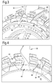
- Figure 3 shows a schematic perspective view of the front of the disc 32
- Figure 4 shows a schematic perspective view of the rear of the disc.
- the cavity at each end of each dovetail root slot creates a trapezoidal space in which the respective retainer plate 44, 46 is positioned with the short parallel edge of the correspondingly trapezoidal plate being radially outwardly of the long parallel edge, and the angled edges of the trapezoidal plate being circumferentially spaced from each other.
- the plate is slotted into the cavity with a radially outwardly directed motion.
- Each cavity has a pair of projections 66 which provide the abutment surfaces for the second side 54 of the plate, the abutment surfaces extending along the angled edges of the plate.
- Figure 7(a) shows a schematic constant radius section through one of the retainer plates 44, 46.
- the plate experiences an axial force F at the centre of its first side 52 from loading contact with the dovetail root 36 of the fan blade, and opposing axial reaction forces R at the circumferentially spaced edges of its second side 54 from contact with the abutment surfaces of the projections 66.
- Figure 7(b) is a further schematic constant radius section through the plate illustrating different stress states caused by the forces and constraints to which the plate is exposed.
- the axial force F and reaction forces R produce a 3-point loading situation which generates in-plane compressive stresses at the centre of the first side 52 and in-plane tensile stresses at the centre of the second side 54.
- physical constraints and the reaction forces R generate locally high stress concentrations, particularly at the second side 54.
- the loading on the plate has a high shear component.
- a first zone of the plate extends through the thickness of the plate from a region on the first side 52 which contacts with the axial end face of the dovetail root. This zone can be sub-divided into a portion C at the first side 52 which experiences high in-plane compressive stresses, and a portion B at the second side 54 which experiences high in-plane tensile stresses.
- Two second zones D of the plate extend through the thickness of the plate from respective edge regions on the second side 54 which contact with the abutment surface of the cavity.
- Two third zones A extend through the thickness of the plate and separate the first zone from a respective one of the second zones, the third zones experiencing high shear stresses.
- the fibre tows of the composite material of the plate are 3D-woven into a pre-form, which is then used to form the final composite material.
- the composite material of these zones which is reinforced by warp and weft fibre tows extending in layers parallel to the plane of the plate (i.e. perpendicularly to the engine axial direction), is also reinforced by angle interlock fibre tows which extend through the thickness of the plate.
- angle interlock fibre tows which extend through the thickness of the plate.
- around 50% of the total number of tows in the third zones can be angle interlock tows.
- These tows can be angled relative to the axial direction to best resist the shear stresses.
- the shear stresses produced in the right hand zone A of Figure 7(b) will have their resolved tensile component at an angle of about 45° to the axial direction in the plane of the drawing.
- the angle interlock tows in this zone can thus be at this angle, aligned with the direction of this component (indicated in Figure 7(b) by a dash-dotted line).
- the angle interlock tows in the left hand zone A can similarly be at an angle of about 45 ° to the axial direction, also aligned along the direction of the resolved tensile component of the shear stress.
- the warp and weft fibre tows extending parallel to the plane can be supplemented by, for example, about 10% of layer-to-layer interlock fibre tows which help to prevent inter-layer delamination and edge splitting, which can be a particular problem when the edges of the plate are trimmed in a final manufacturing step.
- the warp and weft fibre tows extending parallel to the plane can be supplemented by, for example, about 10% of layer-to-layer interlock fibre tows. These also help to prevent inter-layer delamination, in this case caused by the high in-plane compressive stresses generated in portion C.
- the woven pre-form can be cut from a larger 3D-woven shape, with the periphery of the cut pre-form being somewhat beyond the targeted component dimensions to allow for subsequent edge trimming.
- the pre-form may be placed in a mould where resin is added in a resin infusion process (such as resin transfer moulding), and then cured in mould. After removal from the mould, it can be trim machined to the final shape.
Landscapes
- Engineering & Computer Science (AREA)
- Mechanical Engineering (AREA)
- General Engineering & Computer Science (AREA)
- Structures Of Non-Positive Displacement Pumps (AREA)
Abstract
Description
- The present invention relates to a retainer plate for retaining a dovetail root of a fan blade of a gas turbine engine in a corresponding axially-extending slot in the rim of a fan disc.
- Many aero-engines adopt a dovetail style of fan blade root which locates in a corresponding slot formed in the rim of the fan disc. During service operation, the fan assembly is subject to a complex loading system, consisting of centripetal load, gas-bending and vibration. The dovetail geometry copes particularly well with this kind of loading conditions. Retention devices are fitted to restrain axial movement of fan blades resisting thrust loading under normal running and axial loading during fan blade impact events.
- Engine casings must be capable of containing the release of a single compressor or turbine blade, or any likely combinations of blades. In particular, an engine must pass a fan blade-off test to demonstrate mechanical integrity of all systems following the loss of a fan blade. The test is a single-shot exercise, comprising the deliberate release of the portion of a blade outboard of its retention feature at the maximum low pressure shaft speed, either on a full engine or a-fan-blade-off rig.
- When the blade is released, it is retained by the casing and is then hit by the following blade, which tends to push the released blade backward (toward the rear of the engine). In reaction, it produces a force pushing the following blade (still retained by the fan disc) forward. The resulting load can be as much as about 80,000 lbf (356 kN) in the axial direction.
- Bird impacts on fan blades can also cause axial high loads.
- The retention device restraining axial movement of a fan blade must be able to withstand these types of axial load. However, it should also be as light as possible to reduce the weight of the engine.
- Shear keys (see e.g.
US 5624233 ) and thrust rings (see e.g.GB A 2262139 - An aim of the present invention is to provide an improved retention device to restrain axial movement of fan blades.
- Accordingly, in a first aspect, the present invention provides a retainer plate for retaining a dovetail root of a fan blade of a gas turbine engine in a corresponding axially-extending slot in the rim of a fan disc, in use, the plate locating in a cavity formed at an end of the slot such that a first side of the plate is arranged for contact with an axial end face of the dovetail root and an opposite second side of the plate is arranged for contact with an abutment surface of the cavity to limit axial movement of the root along the slot;
wherein the retainer plate is formed from fibre-reinforced composite material, at least a portion of the composite material being reinforced by 3D-woven fibre tows. - A 3D-woven composite material retainer plate can provide significant weight-reduction compared with conventional, typically metallic, shear plates. Alternatively, for the same weight, the strength of the plate can be improved, allowing the plate to withstand greater axial loads. Further, 3D-weaving the reinforcement fibres enhances the ability to vary the alignment of the reinforcing fibres in different parts of the plate depending on the expected stress pattern in the plate.
- The retainer plate of the first aspect may have any one or, to the extent that they are compatible, any combination of the following optional features.
- The retainer plate may have: a first zone which extends through the thickness of the plate from a region on the first side which contacts with the axial end face of the dovetail root, a second zone which extends through the thickness of the plate from a region on the second side which contacts with the abutment surface of the cavity, and a third zone which extends through the thickness of the plate and separates the first zone from the second zone; wherein the composite material of the first to third zones is reinforced by warp and weft fibre tows which extend in layers parallel to the plane of the plate, and the third zone is also reinforced by angle interlock fibre tows which extend through the thickness of the plate. The third zone typically experiences a high shear stress acting through the thickness of the plate. Advantageously, the angle interlock fibre tows in this zone can be aligned along the direction of the tensile component of the resolved shear stress, to provide a significant increase in resistance to the shear stress.
- By "angle interlock fibre tows" we mean tows which would be warp tows if they remained in a given layer of warp and weft tows, but instead, as part of the 3D weaving process, travel through different layers of warp and weft tows, typically from one surface of the eventual plate to the other.
- Viewing the retainer plate along the radial direction, the angle interlock fibre tows in the third zone may be angled at between 30° and 60° to the axial direction. For example, viewed along this direction, the angle interlock fibre tows may be angled at about 45° to the axial direction.
- The angle interlock fibre tows may be at least 25% and/or at most 75% of the total number of tows in the third zone. For example, the angle interlock fibre tows may be about 50% of the total number of tows in the third zone.
- The second zone may also be reinforced by layer-to-layer interlock fibre tows. Advantageously, the layer-to-layer interlock fibre tows in this zone can help to maintain the integrity of the plate, for example when it is being trimmed to shape. The layer-to-layer interlock fibre tows may be at least 2% and/or at most 20% of the total number of tows in the second zone. For example, the layer-to-layer interlock fibre tows may be about 10% of the total number of tows in the second zone.
- By "layer-to-layer interlock fibre tows we mean tows which would be warp tows if they remained in a given layer of warp and weft tows, but instead, as part of the 3D weaving process, travel from one layer of warp and weft tows to an adjacent layer and back again.
- The portion of the first zone at the first side of the retainer plate may also be reinforced by layer-to-layer interlock fibre tows. Advantageously, the layer-to-layer interlock fibre tows in this portion of the first zone can help to resist delamination of the composite material under high compressive in-plane stresses generated when the plate is loaded by the axial end face of the dovetail root. The layer-to-layer interlock fibre tows may be at least 2% and/or at most 20% of the total number of tows in this portion of the first zone. For example, the layer-to-layer interlock fibre tows may be about 10% of the total number of tows in the layer of this first zone.
- Typically the cavity has a pair of abutment surfaces which extend along respective circumferentially-spaced edges of the retainer plate. In this case, the retainer plate may have two second zones, each second zone being located at a respective one of the edges. The first zone can then be centrally located relative to the second zones, and the retainer plate can have two third zones, each third zone separating the first zone from a respective one of the second zones.
- Galvanic corrosion can be a problem particularly when different materials are used for the retainer plate and an adjacent component, such as for a carbon fibre composite material retainer plate and a metal fan disc. The retainer plate may thus have an outer galvanic corrosion protection barrier layer, e.g. at the second side of the plate. The barrier layer may be formed of a polymer matrix composite, such as a glass fibre reinforced composite.
- The retainer plate may have a low friction coating on its first side. This can help to reduce fretting damage to the dovetail root. For example, the coating may be a PTFE coating.
- The retainer plate may be substantially trapezoidal in shape. In use, the parallel edges of the trapezoid can form radially-spaced inner and outer edges of the plate (the shorter parallel edge generally being the radially outer edge), and the angled edges can form circumferentially-spaced edges of the plate.
- In a second aspect, the present invention provides a fan assembly of a gas turbine engine, the assembly having:
- a fan disc;
- a circumferential row of fan blades, each fan blade having a dovetail root which is retained in a corresponding axially-extending slot in the rim of the fan disc; and
- a circumferential row of first retainer plates according to the first aspect;
- wherein each first retainer plate is located in a cavity formed at an end of a respective one of the slots such that the first side of the first retainer plate is arranged for contact with an axial end face of the respective dovetail root and the opposite second side of the first retainer plate is arranged for contact with an abutment surface of the cavity to limit axial movement of the root along the slot.
- The fan assembly may further have:
- a circumferential row of second retainer plates according to the first aspect;
- wherein each second retainer plate is located in a cavity formed at an opposite end of a respective one of the slots such that the first side of the second retainer plate is arranged for contact with an axial end face of the respective dovetail root and the opposite second side of the second retainer plate is arranged for contact with an abutment surface of the cavity to limit axial movement of the root along the slot.
- The first and second retainer plates may have any one or, to the extent that they are compatible, any combination of the optional features of the first aspect discussed above. Further, the fan assembly of the second aspect may have any one or, to the extent that they are compatible, any combination of the following optional features.
- The abutment surface of each cavity may be formed as a pair of abutment surface portions which extend along respective circumferentially-spaced edges of the respective retainer plate.
- The or each circumferential row of retainer plates may be supported by a respective support ring.
- Each fan blade may be radially outwardly chocked in its slot by a respective slider inserted into the slot radially inwardly of the dovetail root. The slider may carry a spring element which urges the fan blade radially outwardly.
- At least the dovetail roots of the fan blades may be formed of polymer matrix, fibre reinforced, composite material, such as carbon fibre reinforced composite material. The retainer plates offer advantages over shear key approaches for restraining axial movement of composite material fan blades. In particular, shear keys generally require slots to be formed in the dovetail root, which on a composite blade may sever fibres in the root. The retainer plates, in contrast, act on the axial end faces.
- In a third aspect, the present invention provides a gas turbine engine having the fan assembly of the second aspect.
- The fan assembly may have any one or, to the extent that they are compatible, any combination of the optional features of the second aspect discussed above.
- Embodiments of the invention will now be described by way of example with reference to the accompanying drawings in which:
-
Figure 1 shows a schematic longitudinal cross-section through a ducted fan gas turbine engine; -
Figure 2 shows a schematic longitudinal cross-section of the mounting region of a fan blade to a fan disc; -
Figure 3 shows a schematic perspective view of the front of the fan disc, and in particular a circumferential row of front retainer plates; -
Figure 4 shows a schematic perspective view of the rear of the fan disc, and in particular a circumferential row of rear retainer plates; -
Figure 5 shows a schematic perspective view of the front of the fan disc, and in particular a support ring for the circumferential row of front retainer plates; -
Figure 6 shows a schematic perspective view of the rear of the fan disc, and in particular a support ring for the circumferential row of rear retainer plates; and -
Figure 7 shows (a) a schematic constant radius section through one of the retainer plates, and (b) a further schematic constant radius section through the plate illustrating different stress states. - With reference to
Figure 1 , a ducted fan gas turbine engine incorporating the invention is generally indicated at 10 and has a principal and rotational axis X-X. The engine comprises, in axial flow series, anair intake 11, apropulsive fan 12, anintermediate pressure compressor 13, a high-pressure compressor 14,combustion equipment 15, a high-pressure turbine 16, anintermediate pressure turbine 17, a low-pressure turbine 18 and a coreengine exhaust nozzle 19. Anacelle 21 generally surrounds theengine 10 and defines theintake 11, abypass duct 22 and abypass exhaust nozzle 23. - During operation, air entering the
intake 11 is accelerated by thefan 12 to produce two air flows: a first air flow A into theintermediate pressure compressor 13 and a second air flow B which passes through thebypass duct 22 to provide propulsive thrust. Theintermediate pressure compressor 13 compresses the air flow A directed into it before delivering that air to thehigh pressure compressor 14 where further compression takes place. - The compressed air exhausted from the high-
pressure compressor 14 is directed into thecombustion equipment 15 where it is mixed with fuel and the mixture combusted. The resultant hot combustion products then expand through, and thereby drive the high, intermediate and low-pressure turbines nozzle 19 to provide additional propulsive thrust. The high, intermediate and low-pressure turbines respectively drive the high andintermediate pressure compressors fan 12 by suitable interconnecting shafts. - The
propulsive fan 12 includes a circumferential row of fan blades secured to a fan disc. The fan blades can be formed of polymer matrix, fibre reinforced, composite material, such as carbon fibre reinforced composite material. -
Figure 2 shows a schematic longitudinal cross-section of the mounting region of one of thefan blades 30 to thefan disc 32. The blade has anaerofoil section 34 and adovetail root 36 which is retained in a corresponding axially-extending slot in therim 38 of the disc. - A
slider 40 andspring 42 assembly is inserted into the slot at the underside of thedovetail root 36 to chock theblade 30 radially outwardly. The slider helps to prevent the spring fretting against thedisc 32. It also helps to prevent the ingress of dirt into cavity beneath the dovetail root. - A trapezoidal
front retainer plate 44 is located in a cavity formed at the front end of the slot to limit forward axial movement of thedovetail root 36 along the slot, and a reartrapezoidal retainer plate 46 is located in a cavity formed at the rear end of the slot to limit rearward axial movement of the dovetail root along the slot. The plates are held in place byfront 48 and rear 50 support rings. - A
first side 52 of eachretainer plate dovetail root 36, and an oppositesecond side 54 of each plate is arranged for contact with abutment surfaces of the respective cavity to limit axial movement of the root along the slot. - The two plates are formed from fibre-reinforced composite material (e.g. polymer matrix, fibre reinforced, composite material, such as carbon fibre reinforced composite material), with at least a portion of the composite material being reinforced by 3D-woven fibre tows.
Figure 3 shows a schematic perspective view of the front of thedisc 32, andFigure 4 shows a schematic perspective view of the rear of the disc. The cavity at each end of each dovetail root slot creates a trapezoidal space in which therespective retainer plate projections 66 which provide the abutment surfaces for thesecond side 54 of the plate, the abutment surfaces extending along the angled edges of the plate. - The trapezoidal form of the
retainer plates Figures 5 and6 , when the engine is stationary, the plates are kept in place byfront 68 and rear 70 support rings, which may be located in circumferentially extending grooves formed in the radially inward edges of the plates. -
Figure 7(a) shows a schematic constant radius section through one of theretainer plates first side 52 from loading contact with thedovetail root 36 of the fan blade, and opposing axial reaction forces R at the circumferentially spaced edges of itssecond side 54 from contact with the abutment surfaces of theprojections 66. -
Figure 7(b) is a further schematic constant radius section through the plate illustrating different stress states caused by the forces and constraints to which the plate is exposed. Thus the axial force F and reaction forces R produce a 3-point loading situation which generates in-plane compressive stresses at the centre of thefirst side 52 and in-plane tensile stresses at the centre of thesecond side 54. At the edges of the plate, physical constraints and the reaction forces R generate locally high stress concentrations, particularly at thesecond side 54. Between these central stresses and edge stresses, the loading on the plate has a high shear component. - It is then possible to define different plate zones based on the types of forces and constraints to which the plate is exposed. A first zone of the plate extends through the thickness of the plate from a region on the
first side 52 which contacts with the axial end face of the dovetail root. This zone can be sub-divided into a portion C at thefirst side 52 which experiences high in-plane compressive stresses, and a portion B at thesecond side 54 which experiences high in-plane tensile stresses. Two second zones D of the plate extend through the thickness of the plate from respective edge regions on thesecond side 54 which contact with the abutment surface of the cavity. Two third zones A extend through the thickness of the plate and separate the first zone from a respective one of the second zones, the third zones experiencing high shear stresses. - To enhance the ability to vary the alignment of reinforcing fibres in different parts of the plate depending on the expected stress pattern in the plate, the fibre tows of the composite material of the plate are 3D-woven into a pre-form, which is then used to form the final composite material.
- In particular, to resist the shear stresses in the third zones A, the composite material of these zones, which is reinforced by warp and weft fibre tows extending in layers parallel to the plane of the plate (i.e. perpendicularly to the engine axial direction), is also reinforced by angle interlock fibre tows which extend through the thickness of the plate. For example, around 50% of the total number of tows in the third zones can be angle interlock tows. These tows can be angled relative to the axial direction to best resist the shear stresses. In particular, the shear stresses produced in the right hand zone A of
Figure 7(b) will have their resolved tensile component at an angle of about 45° to the axial direction in the plane of the drawing. The angle interlock tows in this zone can thus be at this angle, aligned with the direction of this component (indicated inFigure 7(b) by a dash-dotted line). The angle interlock tows in the left hand zone A can similarly be at an angle of about 45 ° to the axial direction, also aligned along the direction of the resolved tensile component of the shear stress. - In the second zones D, the warp and weft fibre tows extending parallel to the plane can be supplemented by, for example, about 10% of layer-to-layer interlock fibre tows which help to prevent inter-layer delamination and edge splitting, which can be a particular problem when the edges of the plate are trimmed in a final manufacturing step.
- Similarly, in portion C of the first zone, the warp and weft fibre tows extending parallel to the plane can be supplemented by, for example, about 10% of layer-to-layer interlock fibre tows. These also help to prevent inter-layer delamination, in this case caused by the high in-plane compressive stresses generated in portion C.
- In practice, the woven pre-form can be cut from a larger 3D-woven shape, with the periphery of the cut pre-form being somewhat beyond the targeted component dimensions to allow for subsequent edge trimming. The pre-form may be placed in a mould where resin is added in a resin infusion process (such as resin transfer moulding), and then cured in mould. After removal from the mould, it can be trim machined to the final shape.
- While the invention has been described in conjunction with the exemplary embodiments described above, many equivalent modifications and variations will be apparent to those skilled in the art when given this disclosure. Accordingly, the exemplary embodiments of the invention set forth above are considered to be illustrative and not limiting. Various changes to the described embodiments may be made without departing from the spirit and scope of the invention.
- All references referred to above are hereby incorporated by reference.
Claims (15)
- A retainer plate (44, 46) for retaining a dovetail root (36) of a fan blade (34) of a gas turbine engine (10) in a corresponding axially-extending slot in the rim (38) of a fan disc (32), in use, the plate locating in a cavity formed at an end of the slot such that a first side (52) of the plate is arranged for contact with an axial end face of the dovetail root and an opposite second side (54) of the plate is arranged for contact with an abutment surface of the cavity to limit axial movement of the root along the slot;
wherein the retainer plate is formed from fibre-reinforced composite material, at least a portion of the composite material being reinforced by 3D-woven fibre tows. - A retainer plate according to claim 1, wherein the retainer plate has:a first zone which extends through the thickness of the plate from a region on the first side which contacts with the axial end face of the dovetail root,a second zone (D) which extends through the thickness of the plate from a region on the second side which contacts with the abutment surface of the cavity, anda third zone (A) which extends through the thickness of the plate and separates the first zone from the second zone;wherein the composite material of the first to third zones is reinforced by warp and weft fibre tows which extend in layers parallel the plane of the plate, and the third zone is also reinforced by angle interlock fibre tows which extend through the thickness of the plate.
- A retainer plate according to claim 2, wherein, viewing the plate along the radial direction, the angle interlock fibre tows are angled at between 30° and 60° to the axial direction.
- A retainer plate according to claim 2 or 3, wherein the angle interlock fibre tows are at least 25% and at most 75% of the total number of tows in the third zone.
- A retainer plate according to any one of claims 2 to 4, wherein the second zone is also reinforced by layer-to-layer interlock fibre tows.
- A retainer plate according to claim 5, wherein the layer-to-layer interlock fibre tows are at least 2% and at most 20% of the total number of tows in the second zone.
- A retainer plate according to any one of claims 2 to 5, wherein a portion (C) of the first zone at the first side of the retainer plate is also reinforced by layer-to-layer interlock fibre tows.
- A retainer plate according to claim 7, wherein the layer-to-layer interlock fibre tows are at least 2% and at most 20% of the total number of tows in this portion of the first zone.
- A retainer plate according to any one of claims 2 to 8, wherein the cavity has a pair of abutment surfaces (66) which extend along respective circumferentially-spaced edges of the retainer plate, and the retainer plate has two second zones, each second zone being located at a respective one of the edges.
- A retainer plate according to claim 9, wherein the first zone is centrally located relative to the second zones, and the retainer plate has two third zones, each third zone separating the first zone from a respective one of the second zones.
- A retainer plate according to any one of the previous claims, wherein the composite material is carbon fibre-reinforced, polymer matrix composite material.
- A fan assembly of a gas turbine engine (10), the assembly having:a fan disc (32);a circumferential row of fan blades (30), each fan blade having a dovetail root (36) which is retained in a corresponding axially-extending slot in the rim (38) of the fan disc; anda circumferential row of first retainer plates (44) according to any one of the previous claims;wherein each first retainer plate is located in a cavity formed at an end of a respective one of the slots such that the first side (52) of the first retainer plate is arranged for contact with an axial end face of the respective dovetail root and the opposite second side (54) of the first retainer plate is arranged for contact with an abutment surface of the cavity to limit axial movement of the root along the slot.
- A fan assembly according to claim 12 which further has:a circumferential row of second retainer plates (46) according to any one of claims 1 to 11;wherein each second retainer plate is located in a cavity formed at an opposite end of a respective one of the slots such that the first side (52) of the second retainer plate is arranged for contact with an axial end face of the respective dovetail root and the opposite second side (54) of the second retainer plate is arranged for contact with an abutment surface of the cavity to limit axial movement of the root along the slot.
- A fan assembly according to any one of claim 12 or 13, wherein at least the dovetail roots of the fan blades are formed of polymer matrix, fibre reinforced, composite material.
- A gas turbine engine (10) having the fan assembly of any one of claims 12 to 14.
Applications Claiming Priority (1)
| Application Number | Priority Date | Filing Date | Title |
|---|---|---|---|
| GB201318623A GB201318623D0 (en) | 2013-10-22 | 2013-10-22 | Retainer plate |
Publications (2)
| Publication Number | Publication Date |
|---|---|
| EP2865849A1 true EP2865849A1 (en) | 2015-04-29 |
| EP2865849B1 EP2865849B1 (en) | 2018-12-19 |
Family
ID=49727133
Family Applications (1)
| Application Number | Title | Priority Date | Filing Date |
|---|---|---|---|
| EP14188731.5A Not-in-force EP2865849B1 (en) | 2013-10-22 | 2014-10-14 | Retainer plate |
Country Status (3)
| Country | Link |
|---|---|
| US (1) | US9745995B2 (en) |
| EP (1) | EP2865849B1 (en) |
| GB (1) | GB201318623D0 (en) |
Families Citing this family (4)
| Publication number | Priority date | Publication date | Assignee | Title |
|---|---|---|---|---|
| EP3129597B1 (en) * | 2014-04-07 | 2018-10-24 | Safran Aircraft Engines | Lock of a rotor of a turbomachine |
| US10024164B2 (en) * | 2016-09-27 | 2018-07-17 | General Electric Company | Fixture for restraining a turbine wheel |
| US10100677B2 (en) * | 2016-09-27 | 2018-10-16 | General Electric Company | Fixture for restraining a turbine wheel |
| US10294801B2 (en) * | 2017-07-25 | 2019-05-21 | United Technologies Corporation | Rotor blade having anti-wear surface |
Citations (4)
| Publication number | Priority date | Publication date | Assignee | Title |
|---|---|---|---|---|
| EP0110744A1 (en) * | 1982-11-08 | 1984-06-13 | Societe Nationale D'etude Et De Construction De Moteurs D'aviation, "S.N.E.C.M.A." | Device for the radial and axial fixation of fan blades |
| GB2262139A (en) * | 1991-12-04 | 1993-06-09 | Rolls Royce Plc | Fan blade retainer |
| US5624233A (en) * | 1995-04-12 | 1997-04-29 | Rolls-Royce Plc | Gas turbine engine rotary disc |
| EP2053199A1 (en) * | 2007-10-22 | 2009-04-29 | Snecma | Turbomachine wheel |
Family Cites Families (9)
| Publication number | Priority date | Publication date | Assignee | Title |
|---|---|---|---|---|
| US5277548A (en) * | 1991-12-31 | 1994-01-11 | United Technologies Corporation | Non-integral rotor blade platform |
| US5281098A (en) * | 1992-10-28 | 1994-01-25 | General Electric Company | Single ring blade retaining assembly |
| FR2889264B1 (en) | 2005-07-29 | 2007-11-02 | Snecma | LOCKING AUBES IN A BLOWER ROTOR |
| FR2900437B1 (en) * | 2006-04-27 | 2008-07-25 | Snecma Sa | SYSTEM FOR RETENTING AUBES IN A ROTOR |
| US8440276B2 (en) * | 2008-02-11 | 2013-05-14 | Albany Engineered Composites, Inc. | Multidirectionally reinforced shape woven preforms for composite structures |
| FR2945329B1 (en) | 2009-05-06 | 2011-06-03 | Snecma | BLOWER ROTOR OF AN AIRCRAFT TURBORACTOR |
| JP5573951B2 (en) * | 2010-07-15 | 2014-08-20 | 株式会社Ihi | Fan blade and fan |
| US9587645B2 (en) * | 2010-09-30 | 2017-03-07 | Pratt & Whitney Canada Corp. | Airfoil blade |
| EP2971549B1 (en) * | 2013-03-15 | 2020-02-12 | Rolls-Royce Corporation | Gas turbine engine blade, corresponding gas turbine engine and method of forming |
-
2013
- 2013-10-22 GB GB201318623A patent/GB201318623D0/en not_active Ceased
-
2014
- 2014-10-14 EP EP14188731.5A patent/EP2865849B1/en not_active Not-in-force
- 2014-10-22 US US14/520,683 patent/US9745995B2/en not_active Expired - Fee Related
Patent Citations (4)
| Publication number | Priority date | Publication date | Assignee | Title |
|---|---|---|---|---|
| EP0110744A1 (en) * | 1982-11-08 | 1984-06-13 | Societe Nationale D'etude Et De Construction De Moteurs D'aviation, "S.N.E.C.M.A." | Device for the radial and axial fixation of fan blades |
| GB2262139A (en) * | 1991-12-04 | 1993-06-09 | Rolls Royce Plc | Fan blade retainer |
| US5624233A (en) * | 1995-04-12 | 1997-04-29 | Rolls-Royce Plc | Gas turbine engine rotary disc |
| EP2053199A1 (en) * | 2007-10-22 | 2009-04-29 | Snecma | Turbomachine wheel |
Also Published As
| Publication number | Publication date |
|---|---|
| GB201318623D0 (en) | 2013-12-04 |
| US20150110634A1 (en) | 2015-04-23 |
| US9745995B2 (en) | 2017-08-29 |
| EP2865849B1 (en) | 2018-12-19 |
Similar Documents
| Publication | Publication Date | Title |
|---|---|---|
| US9145784B2 (en) | Annulus filler system | |
| US11286782B2 (en) | Multi-material leading edge protector | |
| US10655500B2 (en) | Reinforced fan containment case for a gas turbine engine | |
| EP2096269B1 (en) | Fan track liner assembly for a gas turbine engine | |
| CA2645375C (en) | Composite containment casings | |
| US10641287B2 (en) | Fan containment case for a gas turbine engine | |
| EP1650406B1 (en) | Locking assembly for a gas turbine rotor stage | |
| US9745995B2 (en) | Retainer plate | |
| EP2570597A2 (en) | Method of manufacturing a composite filled metal airfoil and corresponding fan blade | |
| US8826536B2 (en) | Blade preloading method | |
| EP2071137B1 (en) | Method for repairing composite containment casings | |
| US11885239B2 (en) | Turbomachine rotary fan blade, fan, and turbomachine provided therewith | |
| US20160265370A1 (en) | Chocking and retaining device | |
| US9803648B2 (en) | Retainer plate | |
| US20080075602A1 (en) | Blades | |
| WO2014039188A1 (en) | Rub tolerant fan case | |
| EP2959131B1 (en) | Composite attachment structure with 3d weave | |
| US3554667A (en) | Turbomachine rotor | |
| US20200157953A1 (en) | Composite fan blade with abrasive tip | |
| US10024178B2 (en) | Chocking and retaining device | |
| EP2837773B1 (en) | Annulus filler and corresponding stage and gas turbine engine | |
| EP4596843A1 (en) | Turbofan gas turbine engine with inner ring reinforcing structure and methods of producing the same |
Legal Events
| Date | Code | Title | Description |
|---|---|---|---|
| PUAI | Public reference made under article 153(3) epc to a published international application that has entered the european phase |
Free format text: ORIGINAL CODE: 0009012 |
|
| 17P | Request for examination filed |
Effective date: 20141014 |
|
| AK | Designated contracting states |
Kind code of ref document: A1 Designated state(s): AL AT BE BG CH CY CZ DE DK EE ES FI FR GB GR HR HU IE IS IT LI LT LU LV MC MK MT NL NO PL PT RO RS SE SI SK SM TR |
|
| AX | Request for extension of the european patent |
Extension state: BA ME |
|
| RAP1 | Party data changed (applicant data changed or rights of an application transferred) |
Owner name: ROLLS-ROYCE PLC |
|
| R17P | Request for examination filed (corrected) |
Effective date: 20151023 |
|
| RBV | Designated contracting states (corrected) |
Designated state(s): AL AT BE BG CH CY CZ DE DK EE ES FI FR GB GR HR HU IE IS IT LI LT LU LV MC MK MT NL NO PL PT RO RS SE SI SK SM TR |
|
| GRAP | Despatch of communication of intention to grant a patent |
Free format text: ORIGINAL CODE: EPIDOSNIGR1 |
|
| STAA | Information on the status of an ep patent application or granted ep patent |
Free format text: STATUS: GRANT OF PATENT IS INTENDED |
|
| GRAS | Grant fee paid |
Free format text: ORIGINAL CODE: EPIDOSNIGR3 |
|
| GRAA | (expected) grant |
Free format text: ORIGINAL CODE: 0009210 |
|
| STAA | Information on the status of an ep patent application or granted ep patent |
Free format text: STATUS: THE PATENT HAS BEEN GRANTED |
|
| INTG | Intention to grant announced |
Effective date: 20181029 |
|
| AK | Designated contracting states |
Kind code of ref document: B1 Designated state(s): AL AT BE BG CH CY CZ DE DK EE ES FI FR GB GR HR HU IE IS IT LI LT LU LV MC MK MT NL NO PL PT RO RS SE SI SK SM TR |
|
| REG | Reference to a national code |
Ref country code: GB Ref legal event code: FG4D |
|
| REG | Reference to a national code |
Ref country code: CH Ref legal event code: EP |
|
| REG | Reference to a national code |
Ref country code: IE Ref legal event code: FG4D |
|
| REG | Reference to a national code |
Ref country code: DE Ref legal event code: R096 Ref document number: 602014038121 Country of ref document: DE |
|
| REG | Reference to a national code |
Ref country code: AT Ref legal event code: REF Ref document number: 1078943 Country of ref document: AT Kind code of ref document: T Effective date: 20190115 |
|
| REG | Reference to a national code |
Ref country code: NL Ref legal event code: MP Effective date: 20181219 |
|
| PG25 | Lapsed in a contracting state [announced via postgrant information from national office to epo] |
Ref country code: BG Free format text: LAPSE BECAUSE OF FAILURE TO SUBMIT A TRANSLATION OF THE DESCRIPTION OR TO PAY THE FEE WITHIN THE PRESCRIBED TIME-LIMIT Effective date: 20190319 Ref country code: HR Free format text: LAPSE BECAUSE OF FAILURE TO SUBMIT A TRANSLATION OF THE DESCRIPTION OR TO PAY THE FEE WITHIN THE PRESCRIBED TIME-LIMIT Effective date: 20181219 Ref country code: FI Free format text: LAPSE BECAUSE OF FAILURE TO SUBMIT A TRANSLATION OF THE DESCRIPTION OR TO PAY THE FEE WITHIN THE PRESCRIBED TIME-LIMIT Effective date: 20181219 Ref country code: LV Free format text: LAPSE BECAUSE OF FAILURE TO SUBMIT A TRANSLATION OF THE DESCRIPTION OR TO PAY THE FEE WITHIN THE PRESCRIBED TIME-LIMIT Effective date: 20181219 Ref country code: NO Free format text: LAPSE BECAUSE OF FAILURE TO SUBMIT A TRANSLATION OF THE DESCRIPTION OR TO PAY THE FEE WITHIN THE PRESCRIBED TIME-LIMIT Effective date: 20190319 Ref country code: LT Free format text: LAPSE BECAUSE OF FAILURE TO SUBMIT A TRANSLATION OF THE DESCRIPTION OR TO PAY THE FEE WITHIN THE PRESCRIBED TIME-LIMIT Effective date: 20181219 |
|
| REG | Reference to a national code |
Ref country code: LT Ref legal event code: MG4D |
|
| REG | Reference to a national code |
Ref country code: AT Ref legal event code: MK05 Ref document number: 1078943 Country of ref document: AT Kind code of ref document: T Effective date: 20181219 |
|
| PG25 | Lapsed in a contracting state [announced via postgrant information from national office to epo] |
Ref country code: GR Free format text: LAPSE BECAUSE OF FAILURE TO SUBMIT A TRANSLATION OF THE DESCRIPTION OR TO PAY THE FEE WITHIN THE PRESCRIBED TIME-LIMIT Effective date: 20190320 Ref country code: RS Free format text: LAPSE BECAUSE OF FAILURE TO SUBMIT A TRANSLATION OF THE DESCRIPTION OR TO PAY THE FEE WITHIN THE PRESCRIBED TIME-LIMIT Effective date: 20181219 Ref country code: SE Free format text: LAPSE BECAUSE OF FAILURE TO SUBMIT A TRANSLATION OF THE DESCRIPTION OR TO PAY THE FEE WITHIN THE PRESCRIBED TIME-LIMIT Effective date: 20181219 Ref country code: AL Free format text: LAPSE BECAUSE OF FAILURE TO SUBMIT A TRANSLATION OF THE DESCRIPTION OR TO PAY THE FEE WITHIN THE PRESCRIBED TIME-LIMIT Effective date: 20181219 |
|
| PG25 | Lapsed in a contracting state [announced via postgrant information from national office to epo] |
Ref country code: NL Free format text: LAPSE BECAUSE OF FAILURE TO SUBMIT A TRANSLATION OF THE DESCRIPTION OR TO PAY THE FEE WITHIN THE PRESCRIBED TIME-LIMIT Effective date: 20181219 |
|
| PG25 | Lapsed in a contracting state [announced via postgrant information from national office to epo] |
Ref country code: PL Free format text: LAPSE BECAUSE OF FAILURE TO SUBMIT A TRANSLATION OF THE DESCRIPTION OR TO PAY THE FEE WITHIN THE PRESCRIBED TIME-LIMIT Effective date: 20181219 Ref country code: ES Free format text: LAPSE BECAUSE OF FAILURE TO SUBMIT A TRANSLATION OF THE DESCRIPTION OR TO PAY THE FEE WITHIN THE PRESCRIBED TIME-LIMIT Effective date: 20181219 Ref country code: PT Free format text: LAPSE BECAUSE OF FAILURE TO SUBMIT A TRANSLATION OF THE DESCRIPTION OR TO PAY THE FEE WITHIN THE PRESCRIBED TIME-LIMIT Effective date: 20190419 Ref country code: CZ Free format text: LAPSE BECAUSE OF FAILURE TO SUBMIT A TRANSLATION OF THE DESCRIPTION OR TO PAY THE FEE WITHIN THE PRESCRIBED TIME-LIMIT Effective date: 20181219 Ref country code: IT Free format text: LAPSE BECAUSE OF FAILURE TO SUBMIT A TRANSLATION OF THE DESCRIPTION OR TO PAY THE FEE WITHIN THE PRESCRIBED TIME-LIMIT Effective date: 20181219 |
|
| PG25 | Lapsed in a contracting state [announced via postgrant information from national office to epo] |
Ref country code: SK Free format text: LAPSE BECAUSE OF FAILURE TO SUBMIT A TRANSLATION OF THE DESCRIPTION OR TO PAY THE FEE WITHIN THE PRESCRIBED TIME-LIMIT Effective date: 20181219 Ref country code: EE Free format text: LAPSE BECAUSE OF FAILURE TO SUBMIT A TRANSLATION OF THE DESCRIPTION OR TO PAY THE FEE WITHIN THE PRESCRIBED TIME-LIMIT Effective date: 20181219 Ref country code: SM Free format text: LAPSE BECAUSE OF FAILURE TO SUBMIT A TRANSLATION OF THE DESCRIPTION OR TO PAY THE FEE WITHIN THE PRESCRIBED TIME-LIMIT Effective date: 20181219 Ref country code: RO Free format text: LAPSE BECAUSE OF FAILURE TO SUBMIT A TRANSLATION OF THE DESCRIPTION OR TO PAY THE FEE WITHIN THE PRESCRIBED TIME-LIMIT Effective date: 20181219 Ref country code: IS Free format text: LAPSE BECAUSE OF FAILURE TO SUBMIT A TRANSLATION OF THE DESCRIPTION OR TO PAY THE FEE WITHIN THE PRESCRIBED TIME-LIMIT Effective date: 20190419 |
|
| REG | Reference to a national code |
Ref country code: DE Ref legal event code: R097 Ref document number: 602014038121 Country of ref document: DE |
|
| PLBE | No opposition filed within time limit |
Free format text: ORIGINAL CODE: 0009261 |
|
| STAA | Information on the status of an ep patent application or granted ep patent |
Free format text: STATUS: NO OPPOSITION FILED WITHIN TIME LIMIT |
|
| PG25 | Lapsed in a contracting state [announced via postgrant information from national office to epo] |
Ref country code: DK Free format text: LAPSE BECAUSE OF FAILURE TO SUBMIT A TRANSLATION OF THE DESCRIPTION OR TO PAY THE FEE WITHIN THE PRESCRIBED TIME-LIMIT Effective date: 20181219 Ref country code: AT Free format text: LAPSE BECAUSE OF FAILURE TO SUBMIT A TRANSLATION OF THE DESCRIPTION OR TO PAY THE FEE WITHIN THE PRESCRIBED TIME-LIMIT Effective date: 20181219 |
|
| 26N | No opposition filed |
Effective date: 20190920 |
|
| PG25 | Lapsed in a contracting state [announced via postgrant information from national office to epo] |
Ref country code: SI Free format text: LAPSE BECAUSE OF FAILURE TO SUBMIT A TRANSLATION OF THE DESCRIPTION OR TO PAY THE FEE WITHIN THE PRESCRIBED TIME-LIMIT Effective date: 20181219 |
|
| PG25 | Lapsed in a contracting state [announced via postgrant information from national office to epo] |
Ref country code: TR Free format text: LAPSE BECAUSE OF FAILURE TO SUBMIT A TRANSLATION OF THE DESCRIPTION OR TO PAY THE FEE WITHIN THE PRESCRIBED TIME-LIMIT Effective date: 20181219 |
|
| PG25 | Lapsed in a contracting state [announced via postgrant information from national office to epo] |
Ref country code: MC Free format text: LAPSE BECAUSE OF FAILURE TO SUBMIT A TRANSLATION OF THE DESCRIPTION OR TO PAY THE FEE WITHIN THE PRESCRIBED TIME-LIMIT Effective date: 20181219 |
|
| REG | Reference to a national code |
Ref country code: CH Ref legal event code: PL |
|
| PG25 | Lapsed in a contracting state [announced via postgrant information from national office to epo] |
Ref country code: LI Free format text: LAPSE BECAUSE OF NON-PAYMENT OF DUE FEES Effective date: 20191031 Ref country code: CH Free format text: LAPSE BECAUSE OF NON-PAYMENT OF DUE FEES Effective date: 20191031 Ref country code: LU Free format text: LAPSE BECAUSE OF NON-PAYMENT OF DUE FEES Effective date: 20191014 |
|
| REG | Reference to a national code |
Ref country code: BE Ref legal event code: MM Effective date: 20191031 |
|
| PG25 | Lapsed in a contracting state [announced via postgrant information from national office to epo] |
Ref country code: BE Free format text: LAPSE BECAUSE OF NON-PAYMENT OF DUE FEES Effective date: 20191031 |
|
| PG25 | Lapsed in a contracting state [announced via postgrant information from national office to epo] |
Ref country code: IE Free format text: LAPSE BECAUSE OF NON-PAYMENT OF DUE FEES Effective date: 20191014 |
|
| PG25 | Lapsed in a contracting state [announced via postgrant information from national office to epo] |
Ref country code: CY Free format text: LAPSE BECAUSE OF FAILURE TO SUBMIT A TRANSLATION OF THE DESCRIPTION OR TO PAY THE FEE WITHIN THE PRESCRIBED TIME-LIMIT Effective date: 20181219 |
|
| PG25 | Lapsed in a contracting state [announced via postgrant information from national office to epo] |
Ref country code: MT Free format text: LAPSE BECAUSE OF FAILURE TO SUBMIT A TRANSLATION OF THE DESCRIPTION OR TO PAY THE FEE WITHIN THE PRESCRIBED TIME-LIMIT Effective date: 20181219 Ref country code: HU Free format text: LAPSE BECAUSE OF FAILURE TO SUBMIT A TRANSLATION OF THE DESCRIPTION OR TO PAY THE FEE WITHIN THE PRESCRIBED TIME-LIMIT; INVALID AB INITIO Effective date: 20141014 |
|
| PG25 | Lapsed in a contracting state [announced via postgrant information from national office to epo] |
Ref country code: MK Free format text: LAPSE BECAUSE OF FAILURE TO SUBMIT A TRANSLATION OF THE DESCRIPTION OR TO PAY THE FEE WITHIN THE PRESCRIBED TIME-LIMIT Effective date: 20181219 |
|
| PGFP | Annual fee paid to national office [announced via postgrant information from national office to epo] |
Ref country code: FR Payment date: 20221024 Year of fee payment: 9 |
|
| PGFP | Annual fee paid to national office [announced via postgrant information from national office to epo] |
Ref country code: GB Payment date: 20221018 Year of fee payment: 9 Ref country code: DE Payment date: 20221028 Year of fee payment: 9 |
|
| P01 | Opt-out of the competence of the unified patent court (upc) registered |
Effective date: 20230528 |
|
| REG | Reference to a national code |
Ref country code: DE Ref legal event code: R119 Ref document number: 602014038121 Country of ref document: DE |
|
| GBPC | Gb: european patent ceased through non-payment of renewal fee |
Effective date: 20231014 |
|
| PG25 | Lapsed in a contracting state [announced via postgrant information from national office to epo] |
Ref country code: GB Free format text: LAPSE BECAUSE OF NON-PAYMENT OF DUE FEES Effective date: 20231014 |
|
| PG25 | Lapsed in a contracting state [announced via postgrant information from national office to epo] |
Ref country code: GB Free format text: LAPSE BECAUSE OF NON-PAYMENT OF DUE FEES Effective date: 20231014 Ref country code: FR Free format text: LAPSE BECAUSE OF NON-PAYMENT OF DUE FEES Effective date: 20231031 Ref country code: DE Free format text: LAPSE BECAUSE OF NON-PAYMENT OF DUE FEES Effective date: 20240501 |