EP2865829A1 - Electric strike plate system - Google Patents
Electric strike plate system Download PDFInfo
- Publication number
- EP2865829A1 EP2865829A1 EP20140189694 EP14189694A EP2865829A1 EP 2865829 A1 EP2865829 A1 EP 2865829A1 EP 20140189694 EP20140189694 EP 20140189694 EP 14189694 A EP14189694 A EP 14189694A EP 2865829 A1 EP2865829 A1 EP 2865829A1
- Authority
- EP
- European Patent Office
- Prior art keywords
- strike plate
- actuator
- electric strike
- plate system
- blocking member
- Prior art date
- Legal status (The legal status is an assumption and is not a legal conclusion. Google has not performed a legal analysis and makes no representation as to the accuracy of the status listed.)
- Granted
Links
Images


Classifications
-
- E—FIXED CONSTRUCTIONS
- E05—LOCKS; KEYS; WINDOW OR DOOR FITTINGS; SAFES
- E05B—LOCKS; ACCESSORIES THEREFOR; HANDCUFFS
- E05B47/00—Operating or controlling locks or other fastening devices by electric or magnetic means
- E05B47/0046—Electric or magnetic means in the striker or on the frame; Operating or controlling the striker plate
-
- G—PHYSICS
- G07—CHECKING-DEVICES
- G07C—TIME OR ATTENDANCE REGISTERS; REGISTERING OR INDICATING THE WORKING OF MACHINES; GENERATING RANDOM NUMBERS; VOTING OR LOTTERY APPARATUS; ARRANGEMENTS, SYSTEMS OR APPARATUS FOR CHECKING NOT PROVIDED FOR ELSEWHERE
- G07C9/00—Individual registration on entry or exit
- G07C9/20—Individual registration on entry or exit involving the use of a pass
-
- E—FIXED CONSTRUCTIONS
- E05—LOCKS; KEYS; WINDOW OR DOOR FITTINGS; SAFES
- E05B—LOCKS; ACCESSORIES THEREFOR; HANDCUFFS
- E05B47/00—Operating or controlling locks or other fastening devices by electric or magnetic means
- E05B2047/0048—Circuits, feeding, monitoring
- E05B2047/005—Opening, closing of the circuit
- E05B2047/0054—Opening, closing of the circuit using microprocessor, printed circuits, or the like
-
- E—FIXED CONSTRUCTIONS
- E05—LOCKS; KEYS; WINDOW OR DOOR FITTINGS; SAFES
- E05B—LOCKS; ACCESSORIES THEREFOR; HANDCUFFS
- E05B47/00—Operating or controlling locks or other fastening devices by electric or magnetic means
- E05B2047/0048—Circuits, feeding, monitoring
- E05B2047/0057—Feeding
- E05B2047/0058—Feeding by batteries
-
- E—FIXED CONSTRUCTIONS
- E05—LOCKS; KEYS; WINDOW OR DOOR FITTINGS; SAFES
- E05B—LOCKS; ACCESSORIES THEREFOR; HANDCUFFS
- E05B47/00—Operating or controlling locks or other fastening devices by electric or magnetic means
- E05B2047/0048—Circuits, feeding, monitoring
- E05B2047/0065—Saving energy
- E05B2047/0066—Reduced holding current
-
- E—FIXED CONSTRUCTIONS
- E05—LOCKS; KEYS; WINDOW OR DOOR FITTINGS; SAFES
- E05B—LOCKS; ACCESSORIES THEREFOR; HANDCUFFS
- E05B47/00—Operating or controlling locks or other fastening devices by electric or magnetic means
- E05B2047/0094—Mechanical aspects of remotely controlled locks
- E05B2047/0095—Mechanical aspects of locks controlled by telephone signals, e.g. by mobile phones
Definitions
- the invention relates to an electric strike plate system comprising an electric strike plate with a movable blocking member, an electric actuator, and a power supply circuit (23, 203), wherein the locking member movement is controlled by means of the actuator, where the actuator is activated in response to a control signal by supplying the actuator with power from the power supply circuit connected to a power source.
- Pivotable elements such as doors or windows, which are hinged in a frame, can often be locked in a closed position by means of a locking unit.
- the locking unit comprises a lock case arranged in the frame on the pivotable element and operates a locking element, such as a latch and/or bolt which can be pushed forward to engage with cooperating openings/recesses in a strike plate arranged in the frame.
- a locking element such as a latch and/or bolt which can be pushed forward to engage with cooperating openings/recesses in a strike plate arranged in the frame.
- an electric strike plate with a blocking member which can be moved away from the latch and/or bolt so that the locking effect is lifted.
- the blocking member movement is maintained or released as needed by means of a lock member, which is engageable with the blocking member.
- the blocking member can be released by means of an electromagnetic actuator, such as a solenoid.
- the blocking member is released as the actuator is activated by switching on the power to the actuator and is kept in released state by maintaining the current through the actuator for as long as the locking effect of the lock should be lifted.
- the current is typically maintained until a person has passed through the door, or at least until the blocking member was released by opening the door with advanced latch/bolt.
- Electric strike plates are known in numerous applications to control the locking function in access doors and other pivotable elements, and it is more and more desirable to be able to remotely control opening and locking functions on existing buildings electrically, and preferably also in combination with some form of electronic access control, for example by wireless communication with an electronic key, mobile phone, or other mobile unit.
- electrically operated locking units including systems with electric strike plate, in existing doors, windows, or gates.
- the object of the invention is to provide an electric strike plate which overcomes at least some of the above disadvantages and which is suitable for retrofitting.
- An electric strike plate system comprises an electric strike plate with a movable blocking member, an electric actuator, and et power supply circuit, wherein the blocking member movement is controlled by means of the actuator, wherein the actuator is activated in response to a control signal by supplying the actuator with power from the power supply circuit connected to a power source, wherein the power supply circuit is adapted to provide a time-dependent voltage sequence with a first voltage level adapted to change the actuator state from deactivated to activated, followed by a second voltage level, which is lower than the first voltage level, adapted to maintain activated state of the actuator.
- a movable member When the actuator is moved from the deactivated state to the activated state, a movable member is usually moved from a rest position to a working position. In order to maintain the activated state of the actuator, the movable member is typically merely retained in the operating position, for example against a spring load.
- the voltage sequence achieves a reduction in power consumption as an increased voltage level is applied to the actuator only to move the movable member, while a lower voltage level with a lower power consumption is sufficient for retaining the movable member in its operating position.
- the electric strike plate with movable blocking member may be an existing electric strike plate already installed in a door/window/gate, or be an off-the-shelf-item, where the electric strike plate is provided with a prior art actuator, such as, for example, a solenoid operated at a supply voltage between 5 and 24 V, typically about 12 V or about 24 V.
- a prior art actuator such as, for example, a solenoid operated at a supply voltage between 5 and 24 V, typically about 12 V or about 24 V.
- the power supply circuit comprises a charge pump circuit.
- the charge pump circuit is adapted to increase the power supply output voltage as compard to the voltage supplied by the power source.
- a pump capacitor is charged from the power source by means of a switching circuit, which typically operates at switching frequencies in the kHz or MHz range.
- the pump capacitor is discharged by supplying a voltage pulse to a load on the output side of the power supply circuit.
- the charge pump circuit is connected when the control signal requests activation of the actuator and is released to supply the first voltage level on the power supply output to bring the actuator from the deactivated state to the activated state as soon as an appropriate voltage has been achieved by means of the charge pump circuit. Subsequently, when the actuator has been brought to the activated state, the power supply output voltage drops from the first voltage level to the second, lower voltage level, e.g. corresponding to the power source voltage level.
- the second voltage level entails a lower energy consumption, but is sufficient for maintaining the activated state of the actuator for as long as is wanted/needed. Thereby, an energy-conserving voltage sequence is obtained in a simple and energy-efficient manner, as indicated above.
- the power source comprises one or more batteries.
- an electric strike plate system is achieved, which is independent of external power sources, and which is therefore easy to retrofit locally, for example in an existing access door, without the need for major installation measures. Because of the energy-saving voltage sequence, the battery will last longer than it would otherwise.
- a power supply comprising a charge pump circuit is advantageous in that it allows use of a battery unit with lower output voltage.
- the second voltage level can be maintained by means of the charge pump circuit.
- the charge pump circuit can be controlled by the MCU to compensate if the power source voltage level alone is not sufficient to maintain the actuator activated state.
- the charge pump circuit is supplied from the power source and operated to supply an, relative to the power source, increased voltage on the power supply output to maintain the actuator activated state.
- the second voltage level is lower than the first voltage level, but higher than the power source voltage level. This may be an advantage, for example, when the battery voltage in a battery-powered system decreases over time, since the time of replacing the batteries can be postponed thereby.
- the actuator operates a lock member which retains the blocking member when the lock member is in engagement with the blocking member. Similarly, the blocking member is released when the lock member is not in engagement with the blocking member.
- the blocking member movement is released when the actuator is activated.
- This embodiment is advantageous, because usually it has the lowest power consumption as the actuator only consumes power to lift the locking effect, while the actuator does not consume power to maintain the locking effect ("current-less closed").
- the actuator is a solenoid.
- the control signal is provided by a microcontroller (MCU) on the basis of an input signal from an input unit, which is in communication with the MCU.
- MCU microcontroller
- the input unit is one or more of an electronic lock cylinder, a keyboard, a touch screen, a biometric reader unit, a card reader, a chip reader.
- the input unit is a wireless communication unit adapted to receive/exchange identification information and/or an access code from a mobile unit.
- the mobile unit may be of any suitable type, such as a mobile phone, a hardware token, a key with integrated ID chip, or the like.
- the wireless communication is local and is established directly between a mobile unit and the strike plate/strike plate system input unit.
- the wireless communication unit uses a standardized technology for wireless communication over short distances, such as Bluetooth, 'Near Field Communication' (NFC), RFID, or the like.
- a standardized technology for wireless communication over short distances such as Bluetooth, 'Near Field Communication' (NFC), RFID, or the like.
- the wireless communication unit is adapted to be started or woken up from a sleep mode on the basis of a wake-up signal generated by a wake-up unit, such as a wake-up button, a motion sensor, a proximity sensor, or the like.
- a wake-up unit such as a wake-up button, a motion sensor, a proximity sensor, or the like.
- an electric locking unit comprises an electric strike plate system according to one or more of the mentioned embodiments, and a lock case with a locking element that can be deployed, such as a bolt and/or latch, where the locking element is adapted for cooperating with the strike plate blocking member to create a locking effect.
- the locking effect occurs in known manner when the locking element is deployed and the blocking member is in the fixed state, and the locking effect between the deployed locking element and the blocking member is lifted when the blocking member movement is released.
- door locks which are typically provided with both bolt and latch as locking elements, it is preferably the latch which cooperates with the movable blocking member of the electric strike plate, while the bolt is adapted to cooperate with a fixed strike plate in order to be able to maintain the locking effect independently of the electric strike plate.
- FIG. 1 shows schematically a locking unit on an access door 1, which is pivotally hinged in a frame 2.
- the door 1 is provided with a lock case 3, which as locking element comprises a latch and/or bolt 4 which can be operated manually and/or be motor-operated by control elements 5, 6.
- the latch and/or bolt 4 cooperate(s) with an electric strike plate 7 in order to achieve a locking effect in a known manner when the latch and/or bolt 4 is/are in a deployed position.
- the electric strike plate 7 has a blocking member 8 which is pivotable about an axis of rotation 9 oriented substantially parallel to the frame 2.
- the blocking member 8 movement is controlled by an actuator 10 via lock member 11.
- the blocking member 8 is retained in a closed position when the lock member 11 is brought into engagement with the blocking member 8.
- the electric strike plate 7 with pivotable blocking member 8 may be an existing electric strike plate already mounted in a door, or be an off-the-shelf-item, where the electric strike plate is provided with an actuator of known type, such as, for example, a solenoid operated with a supply voltage of 5-24 V.
- the lock member 11 is in engagement with the blocking member 8 when the actuator 10 is in a deactivated state (current-less closed).
- a deactivated state current-less closed.
- the actuator 10 moves the lock member 11 out of engagement with the blocking member 8 so that it is released, and the locking effect is lifted.
- the blocking member 8 is released as long as the actuator 10 is held in the activated state.
- the electric strike plate 7 is combined with a control unit 20, which supplies the actuator with power via a power supply 23 from a power source 22, such as one or more 1.5 V batteries of type AA.
- the power supply 23 is adapted to provide an activation pulse for activating the actuator 10, where the activation pulse voltage reaches a first voltage level which is sufficient for moving the lock member 11 and subsequently to provide a holding current at a second voltage level to maintain the activated state of the actuator 10, where the second voltage level of the holding current is lower than the first voltage level of the activation pulse.
- the first voltage level is at least 50% higher than, alternatively 100% higher than, or preferably 5-10 times as high as the power source 22 output voltage.
- the second voltage level corresponds to the power source 22 output voltage.
- the power supply 23 generates the time-dependent voltage sequence with an activation pulse followed by a holding voltage, preferably by means of a charge pump circuit, as further discussed below.
- the power supply 23, and thus the actuator 10, is controlled by means of a microcontroller (MCU) 24 on the basis of an input signal received from a mobile unit 40 via a wireless communication unit 21.
- the input signal is typically a request for access based on identification information (ID), which is transmitted from the mobile unit 40, or is entered via it. If access is to be granted, the MCU sends a control signal to the power supply 23 to lift the locking effect.
- ID identification information
- the power supply 23 activates the actuator 10 and keeps it activated to lift the locking effect until the door 1 has been opened and/or until a specified period of time has elapsed.
- the wireless connection 41 may be established ad hoc between the mobile unit 40 and the wireless communication unit 21, where all necessary exchange can be made automatically and without user input - unless the control unit asks for information that is not stored on the mobile unit 40.
- the control unit or parts thereof, and especially the wireless communication unit can be put into sleep mode and be woken-up for operation from a wake-up unit 30 by operating a wake-up switch 31 disposed at the door and being coupled to the control unit 20 via connection 33.
- the wake-up unit 30 may further comprise a visualization device 32, such as LEDs or a display, which indicates the battery state when the wake-up unit 31 is operated and/or displays whether access may be granted or shall be denied.
- the wake-up unit 30 may further comprise a terminal for connecting an external battery (not shown).
- the wake-up unit 30 may be connected to the wireless communication unit 21 to wake it up directly and/or via the MCU 24.
- FIG. 2 shows a schematic block diagram of the control unit 20 and the units 10, 30, 40 which during operation are in communication with the control unit 20: the actuator 10 is connected to the control unit 20 via connection 12; the wake-up unit 30 exchanges signals with the control unit 20 via connection 33; and the mobile unit 40 communicates wirelessly with the controller 20 via the wireless connection 41.
- the control unit 20 comprises a main board 200, a module 210 for wireless communication, for example a Bluetooth module, and a battery 220.
- the main board 200 has a connection circuit 201 for external connections; a power supply unit 202 for supplying the components/parts of the main board 200 with power from the battery 220; an actuator supply circuit 203 with charge pump; a microcontroller (MCU) 204 handling the control unit program logic; a data management unit 205; and a control unit 206 for communicating with the wireless communication module 210.
- the battery 220 supplies the main board 200 with power via connection 221, and via the power supply unit 202, the actuator supply circuit 203, and connection 12 also the actuator 10.
- the wireless communication module 210 is, via control unit 206 and connection 214, supplied with power from the battery 220.
- the wireless communication module 210 may itself be equipped with a microcontroller and communication unit 211, and handles the actual wireless communication and data management by means of the modules 212, 213.
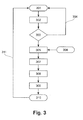
- FIG. 3 shows a flowchart of a program sequence 300 in a current-less closed electric strike plate according to an embodiment of the invention.
- the program is started by input in the form of a wake-up signal at step 301.
- Step 301 may further comprise a battery check and report the battery status, for example as LED light signal.
- the wireless communication module is started in step 302.
- the communication module now awaits a signal from a mobile unit to establish a wireless connection. If no valid signal is received within a given period of time (“timeout”), for example within one minute, the system goes back into sleep mode at loop 304 until a new input wakes up the system again at step 301.
- timeout a period of time
- the charge pump circuit is started in step 305 in order to charge a pump capacitor from the battery to a first voltage level above the battery output voltage.
- the power source output voltage may be 3-6 V
- the pump capacitor is charged to a first voltage level of 24 V, i.e. about 5-10 times the power source output voltage.
- the power source may have a supply voltage between 1 V and 10 V, alternatively between 2 V and 8 V, alternatively between 3 V and 6 V.
- the power source supply voltage corresponds to the voltage of a conventional battery, or a combination of several conventional batteries, such as 1.5 V batteries.
- the batteries can be of a rechargeable type.
- a user coming from the inside, who wishes to leave the closed area can also request that the locking effect be lifted. Since it is often not desired to check the people who leave a closed area, this request to leave the area may advantageously merely be produced as a single signal, for example by pressing an activation button ("EXIT button"), as shown in step 306.
- EXIT button an activation button
- the pump capacitor has been charged to the first voltage level (step 307), for example 24 V, it is released to generate an activation pulse with the first voltage level in step 308, and the blocking member movement is released in step 309; optionally while simultaneously giving off a sound signal.
- the actuator When the activation pulse has activated the actuator so as to lift the locking effect in steps 308, 309, the actuator is, in step 310, supplied with a holding current at a second voltage level corresponding to the battery output voltage, which is sufficient for maintaining the activated state. After a time-delay, the system goes back into sleep mode at loop 311 until it is woken up again by a wake-up signal in step 301.
- FIG. 4 shows a schematic circuit diagram of a charge pump circuit in an electric strike plate system according to an embodiment of the invention.
- the charge pump circuit is part of the power supply to the actuator, which is here a solenoid.
- the charge pump circuit is adapted to build up ("pump") energy in a pump capacitor with a voltage level that is suitable for activating the strike plate actuator.
- DC supply voltage (from battery) is applied onto the VBAT electrode via a pump switch Q4 to chassis ground GND.
- the pump switch Q4 may be a MOSFET with drain (D), source (S), and gate (G) electrodes.
- D-S drain-source-channel
- the drain-source-channel (D-S) of the pump switch Q4 is controlled by the SW signal on the gate G of the pump switch Q4.
- a DC current runs from VBAT via an energy-storing and time-delaying pump coil L1 and the D-S channel of the pump switch Q4 to chassis ground GND.
- the current from the pump coil L1 is forced through the diode D5 to the pump capacitor C9, which thereby takes up charges unable to leave C9 because of the directivity of the diode D5.
- the pump coil L1 entails a time delay in the system response to changes in the state of the D-S channel of the pump switch Q4.
- the pump switch Q4 is opened and closed at such speed that the current does not reach chassis ground GND until the pump switch-over Q4 is interrupted and thereby forces the energy stored in the pump coil L1 over to the pump capacitor C9; whereafter the pump switch Q4 is immediately opened again as soon as the charge transport stops.
- the SW signal operates at a frequency adapted to the time constants following from the components L1 and C9, and C9 is charged from VBAT stepwise in pace with the SW signal. In this way, the pump capacitor C9 is charged to a potential corresponding to the first voltage level and is now ready for activating the electric strike plate actuator.
- FIG. 5 shows a schematic circuit diagram of a release circuit in an electric strike plate system according to an embodiment of the invention.
- the release circuit is part of the power supply to the electric strike plate actuator, which is here a solenoid (not shown).
- the release circuit is arranged to send the energy built up in the pump capacitor C9 of the charge pump circuit (see Fig. 4 ) as an activation pulse through the solenoid and subsequently to supply the solenoid with a DC holding current at a voltage level corresponding to the system DC supply voltage from the battery (VBAT).
- the release circuit is controlled by a control signal RELEASE, which operates the switch Q3.
- the switch Q3 may advantageously be a MOSFET with drain (D), source (S), and gate (G) electrodes.
- the electrodes SOLENOID1 in Fig. 5 and SOLENOID1 in Fig. 4 are connected to one side of the solenoid.
- the electrode SOLENOID2 in Fig. 5 is connected to the other side of the solenoid, which via the DS channel of the switch Q3 is connected to chassis ground GND.
- the release circuit may further comprise a protective circuit with components for protecting the solenoid, such as the diode D6, which is coupled in parallel to the solenoid.
- the solenoid is activated by bringing the D-S channel of the switch Q3 into conductive state so that current can run to chassis ground GND.
- the energy built up in the pump capacitor C9 is now released to generate a current pulse at the first voltage level.
- the current pulse runs through the solenoid, whereby it is brought from the deactivated to the activated state.
- the voltage level drops to the second, lower voltage level, here corresponding to the battery voltage VBAT, which is sufficient for maintaining a DC holding current which maintains the activated state of the solonoid until the switch Q3 is again switched off, and the solenoid returns to the deactivated state.
Landscapes
- Physics & Mathematics (AREA)
- General Physics & Mathematics (AREA)
- Lock And Its Accessories (AREA)
Description
- The invention relates to an electric strike plate system comprising an electric strike plate with a movable blocking member, an electric actuator, and a power supply circuit (23, 203), wherein the locking member movement is controlled by means of the actuator, where the actuator is activated in response to a control signal by supplying the actuator with power from the power supply circuit connected to a power source.
- Pivotable elements, such as doors or windows, which are hinged in a frame, can often be locked in a closed position by means of a locking unit. The locking unit comprises a lock case arranged in the frame on the pivotable element and operates a locking element, such as a latch and/or bolt which can be pushed forward to engage with cooperating openings/recesses in a strike plate arranged in the frame. To be able to open the pivotable element without having to pull the latch and/or bolt back in the lock case, there is arranged an electric strike plate with a blocking member which can be moved away from the latch and/or bolt so that the locking effect is lifted. Typically, the blocking member movement is maintained or released as needed by means of a lock member, which is engageable with the blocking member. In an electric strike plate, the blocking member can be released by means of an electromagnetic actuator, such as a solenoid. In a common variant, the blocking member is released as the actuator is activated by switching on the power to the actuator and is kept in released state by maintaining the current through the actuator for as long as the locking effect of the lock should be lifted. For example, in the case of a door, the current is typically maintained until a person has passed through the door, or at least until the blocking member was released by opening the door with advanced latch/bolt. Electric strike plates are known in numerous applications to control the locking function in access doors and other pivotable elements, and it is more and more desirable to be able to remotely control opening and locking functions on existing buildings electrically, and preferably also in combination with some form of electronic access control, for example by wireless communication with an electronic key, mobile phone, or other mobile unit. There is therefore an increasing need for retrofitting electrically operated locking units, including systems with electric strike plate, in existing doors, windows, or gates.
- The disadvantage of known electric strike plates of the type described above is relatively high energy consumption while the blocking member released state is maintained. The high energy consumption also makes it very difficult to reliably operate such electric strike plates by means of batteries and hence requires major installation measures also at retrofitting.
- The object of the invention is to provide an electric strike plate which overcomes at least some of the above disadvantages and which is suitable for retrofitting.
- The invention solves this problem by means of an electric strike plate according to
claim 1. Advantageous embodiments appear from the claims dependent thereof. - An electric strike plate system according to one embodiment of the invention comprises an electric strike plate with a movable blocking member, an electric actuator, and et power supply circuit, wherein the blocking member movement is controlled by means of the actuator, wherein the actuator is activated in response to a control signal by supplying the actuator with power from the power supply circuit connected to a power source, wherein the power supply circuit is adapted to provide a time-dependent voltage sequence with a first voltage level adapted to change the actuator state from deactivated to activated, followed by a second voltage level, which is lower than the first voltage level, adapted to maintain activated state of the actuator.
- When the actuator is moved from the deactivated state to the activated state, a movable member is usually moved from a rest position to a working position. In order to maintain the activated state of the actuator, the movable member is typically merely retained in the operating position, for example against a spring load. Thus, the voltage sequence achieves a reduction in power consumption as an increased voltage level is applied to the actuator only to move the movable member, while a lower voltage level with a lower power consumption is sufficient for retaining the movable member in its operating position.
- One advantage of the electric strike plate system according to the invention is that the electric strike plate with movable blocking member may be an existing electric strike plate already installed in a door/window/gate, or be an off-the-shelf-item, where the electric strike plate is provided with a prior art actuator, such as, for example, a solenoid operated at a supply voltage between 5 and 24 V, typically about 12 V or about 24 V.
- According to a further embodiment of the electric strike plate system, the power supply circuit comprises a charge pump circuit. The charge pump circuit is adapted to increase the power supply output voltage as compard to the voltage supplied by the power source. When the charge pump circuit is connected, it is supplied from the power source, and a pump capacitor is charged from the power source by means of a switching circuit, which typically operates at switching frequencies in the kHz or MHz range. When the voltage built up in the charge pump circuit is to be released, the pump capacitor is discharged by supplying a voltage pulse to a load on the output side of the power supply circuit. The charge pump circuit is connected when the control signal requests activation of the actuator and is released to supply the first voltage level on the power supply output to bring the actuator from the deactivated state to the activated state as soon as an appropriate voltage has been achieved by means of the charge pump circuit. Subsequently, when the actuator has been brought to the activated state, the power supply output voltage drops from the first voltage level to the second, lower voltage level, e.g. corresponding to the power source voltage level. The second voltage level entails a lower energy consumption, but is sufficient for maintaining the activated state of the actuator for as long as is wanted/needed. Thereby, an energy-conserving voltage sequence is obtained in a simple and energy-efficient manner, as indicated above.
- According to a further embodiment of the electric strike plate system, the power source comprises one or more batteries. Thereby an electric strike plate system is achieved, which is independent of external power sources, and which is therefore easy to retrofit locally, for example in an existing access door, without the need for major installation measures. Because of the energy-saving voltage sequence, the battery will last longer than it would otherwise. Here, especially the combination with a power supply comprising a charge pump circuit is advantageous in that it allows use of a battery unit with lower output voltage.
- According to a further embodiment of the electric strike plate system, the second voltage level can be maintained by means of the charge pump circuit. Thus, the charge pump circuit can be controlled by the MCU to compensate if the power source voltage level alone is not sufficient to maintain the actuator activated state. In this case, the charge pump circuit is supplied from the power source and operated to supply an, relative to the power source, increased voltage on the power supply output to maintain the actuator activated state. Thus, the second voltage level is lower than the first voltage level, but higher than the power source voltage level. This may be an advantage, for example, when the battery voltage in a battery-powered system decreases over time, since the time of replacing the batteries can be postponed thereby.
- According to a further embodiment of the electric strike plate system, the actuator operates a lock member which retains the blocking member when the lock member is in engagement with the blocking member. Similarly, the blocking member is released when the lock member is not in engagement with the blocking member.
- According to a further embodiment of the electric strike plate system, the blocking member movement is released when the actuator is activated. This embodiment is advantageous, because usually it has the lowest power consumption as the actuator only consumes power to lift the locking effect, while the actuator does not consume power to maintain the locking effect ("current-less closed").
- According to a further embodiment of the electric strike plate system, the actuator is a solenoid.
- According to a further embodiment of the electric strike plate system, the control signal is provided by a microcontroller (MCU) on the basis of an input signal from an input unit, which is in communication with the MCU.
- According to a further embodiment of the electric strike plate system, the input unit is one or more of an electronic lock cylinder, a keyboard, a touch screen, a biometric reader unit, a card reader, a chip reader.
- According to a particularly advantageous embodiment of the electric strike plate system, the input unit is a wireless communication unit adapted to receive/exchange identification information and/or an access code from a mobile unit. The mobile unit may be of any suitable type, such as a mobile phone, a hardware token, a key with integrated ID chip, or the like.
- In a further advantageous embodiment, the wireless communication is local and is established directly between a mobile unit and the strike plate/strike plate system input unit.
- In a further advantageous embodiment of the electric strike plate system, the wireless communication unit uses a standardized technology for wireless communication over short distances, such as Bluetooth, 'Near Field Communication' (NFC), RFID, or the like.
- In a further advantageous embodiment of the electric strike plate system, the wireless communication unit is adapted to be started or woken up from a sleep mode on the basis of a wake-up signal generated by a wake-up unit, such as a wake-up button, a motion sensor, a proximity sensor, or the like.
- According to a further aspect, an electric locking unit comprises an electric strike plate system according to one or more of the mentioned embodiments, and a lock case with a locking element that can be deployed, such as a bolt and/or latch, where the locking element is adapted for cooperating with the strike plate blocking member to create a locking effect. The locking effect occurs in known manner when the locking element is deployed and the blocking member is in the fixed state, and the locking effect between the deployed locking element and the blocking member is lifted when the blocking member movement is released. As regards door locks, which are typically provided with both bolt and latch as locking elements, it is preferably the latch which cooperates with the movable blocking member of the electric strike plate, while the bolt is adapted to cooperate with a fixed strike plate in order to be able to maintain the locking effect independently of the electric strike plate.
- In the following, the invention will be further described with reference to an advantageous embodiment as shown in the drawing. In the drawing,
-
FIG. 1 shows, schematically, a locking unit with an electric strike plate system according to an embodiment of the invention; -
FIG. 2 shows, schematically, a block diagram of a control unit for an electric strike plate system according to an embodiment of the invention; -
FIG. 3 shows a flowchart of the programmed control of the opening function of an electric strike plate system according to an embodiment of the invention; -
FIG. 4 shows a schematic circuit diagram of a charge pump circuit in an electric strike plate system according to an embodiment of the invention, and -
FIG. 5 shows a schematic circuit diagram of a release circuit in an electric strike plate system according to an embodiment of the invention. -
FIG. 1 shows schematically a locking unit on anaccess door 1, which is pivotally hinged in aframe 2. Thedoor 1 is provided with alock case 3, which as locking element comprises a latch and/orbolt 4 which can be operated manually and/or be motor-operated bycontrol elements bolt 4 cooperate(s) with anelectric strike plate 7 in order to achieve a locking effect in a known manner when the latch and/orbolt 4 is/are in a deployed position. Theelectric strike plate 7 has a blockingmember 8 which is pivotable about an axis ofrotation 9 oriented substantially parallel to theframe 2. The blockingmember 8 movement is controlled by anactuator 10 vialock member 11. The blockingmember 8 is retained in a closed position when thelock member 11 is brought into engagement with the blockingmember 8. Otherwise, the blockingmember 8 movement is released, and the locking effect is lifted. The door can now be opened even if thelocking element 4 of thelock case 3 is deployed. Theelectric strike plate 7 withpivotable blocking member 8 may be an existing electric strike plate already mounted in a door, or be an off-the-shelf-item, where the electric strike plate is provided with an actuator of known type, such as, for example, a solenoid operated with a supply voltage of 5-24 V. - In a preferred embodiment, the
lock member 11 is in engagement with the blockingmember 8 when theactuator 10 is in a deactivated state (current-less closed). When theactuator 10 is brought into an activated state, theactuator 10 moves thelock member 11 out of engagement with the blockingmember 8 so that it is released, and the locking effect is lifted. The blockingmember 8 is released as long as theactuator 10 is held in the activated state. - According to the invention, the
electric strike plate 7 is combined with acontrol unit 20, which supplies the actuator with power via apower supply 23 from apower source 22, such as one or more 1.5 V batteries of type AA. Thepower supply 23 is adapted to provide an activation pulse for activating theactuator 10, where the activation pulse voltage reaches a first voltage level which is sufficient for moving thelock member 11 and subsequently to provide a holding current at a second voltage level to maintain the activated state of theactuator 10, where the second voltage level of the holding current is lower than the first voltage level of the activation pulse. Preferably, the first voltage level is at least 50% higher than, alternatively 100% higher than, or preferably 5-10 times as high as thepower source 22 output voltage. Further, preferably the second voltage level corresponds to thepower source 22 output voltage. Thepower supply 23 generates the time-dependent voltage sequence with an activation pulse followed by a holding voltage, preferably by means of a charge pump circuit, as further discussed below. - The
power supply 23, and thus theactuator 10, is controlled by means of a microcontroller (MCU) 24 on the basis of an input signal received from amobile unit 40 via awireless communication unit 21. The input signal is typically a request for access based on identification information (ID), which is transmitted from themobile unit 40, or is entered via it. If access is to be granted, the MCU sends a control signal to thepower supply 23 to lift the locking effect. As regards the above "current-less closed" embodiment, this means that thepower supply 23 activates theactuator 10 and keeps it activated to lift the locking effect until thedoor 1 has been opened and/or until a specified period of time has elapsed. - The
wireless connection 41 may be established ad hoc between themobile unit 40 and thewireless communication unit 21, where all necessary exchange can be made automatically and without user input - unless the control unit asks for information that is not stored on themobile unit 40. In order to avoid unnecessary energy consumption, the control unit or parts thereof, and especially the wireless communication unit, can be put into sleep mode and be woken-up for operation from a wake-upunit 30 by operating a wake-up switch 31 disposed at the door and being coupled to thecontrol unit 20 viaconnection 33. The wake-upunit 30 may further comprise avisualization device 32, such as LEDs or a display, which indicates the battery state when the wake-upunit 31 is operated and/or displays whether access may be granted or shall be denied. The wake-upunit 30 may further comprise a terminal for connecting an external battery (not shown). The wake-upunit 30 may be connected to thewireless communication unit 21 to wake it up directly and/or via theMCU 24. -
FIG. 2 shows a schematic block diagram of thecontrol unit 20 and theunits actuator 10 is connected to thecontrol unit 20 viaconnection 12; the wake-upunit 30 exchanges signals with thecontrol unit 20 viaconnection 33; and themobile unit 40 communicates wirelessly with thecontroller 20 via thewireless connection 41. Thecontrol unit 20 comprises amain board 200, amodule 210 for wireless communication, for example a Bluetooth module, and abattery 220. Themain board 200 has aconnection circuit 201 for external connections; apower supply unit 202 for supplying the components/parts of themain board 200 with power from thebattery 220; anactuator supply circuit 203 with charge pump; a microcontroller (MCU) 204 handling the control unit program logic; adata management unit 205; and acontrol unit 206 for communicating with thewireless communication module 210. Thebattery 220 supplies themain board 200 with power viaconnection 221, and via thepower supply unit 202, theactuator supply circuit 203, andconnection 12 also theactuator 10. In addition, also thewireless communication module 210 is, viacontrol unit 206 andconnection 214, supplied with power from thebattery 220. Thewireless communication module 210 may itself be equipped with a microcontroller andcommunication unit 211, and handles the actual wireless communication and data management by means of themodules -
Figure 3 shows a flowchart of a program sequence 300 in a current-less closed electric strike plate according to an embodiment of the invention. The program is started by input in the form of a wake-up signal atstep 301. Step 301 may further comprise a battery check and report the battery status, for example as LED light signal. As a result of the wake-up signal, the wireless communication module is started instep 302. Instep 303, the communication module now awaits a signal from a mobile unit to establish a wireless connection. If no valid signal is received within a given period of time ("timeout"), for example within one minute, the system goes back into sleep mode atloop 304 until a new input wakes up the system again atstep 301. The same thing happens if a wireless communication is established instep 303, but a request for access cannot be met on the basis of the information exchanged. If, on the other hand, the system receives a valid request for access instep 303, the charge pump circuit is started instep 305 in order to charge a pump capacitor from the battery to a first voltage level above the battery output voltage. For example, the power source output voltage may be 3-6 V, whereas the pump capacitor is charged to a first voltage level of 24 V, i.e. about 5-10 times the power source output voltage. For example, the power source may have a supply voltage between 1 V and 10 V, alternatively between 2 V and 8 V, alternatively between 3 V and 6 V. Advantageously, the power source supply voltage corresponds to the voltage of a conventional battery, or a combination of several conventional batteries, such as 1.5 V batteries. In a variant, the batteries can be of a rechargeable type. - Alternatively to a request for access to a closed area from a user coming from the outside, a user coming from the inside, who wishes to leave the closed area, can also request that the locking effect be lifted. Since it is often not desired to check the people who leave a closed area, this request to leave the area may advantageously merely be produced as a single signal, for example by pressing an activation button ("EXIT button"), as shown in
step 306. When the pump capacitor has been charged to the first voltage level (step 307), for example 24 V, it is released to generate an activation pulse with the first voltage level instep 308, and the blocking member movement is released instep 309; optionally while simultaneously giving off a sound signal. When the activation pulse has activated the actuator so as to lift the locking effect insteps step 310, supplied with a holding current at a second voltage level corresponding to the battery output voltage, which is sufficient for maintaining the activated state. After a time-delay, the system goes back into sleep mode atloop 311 until it is woken up again by a wake-up signal instep 301. -
FIG. 4 shows a schematic circuit diagram of a charge pump circuit in an electric strike plate system according to an embodiment of the invention. The charge pump circuit is part of the power supply to the actuator, which is here a solenoid. The charge pump circuit is adapted to build up ("pump") energy in a pump capacitor with a voltage level that is suitable for activating the strike plate actuator. DC supply voltage (from battery) is applied onto the VBAT electrode via a pump switch Q4 to chassis ground GND. Advantageously, the pump switch Q4 may be a MOSFET with drain (D), source (S), and gate (G) electrodes. The drain-source-channel (D-S) of the pump switch Q4 is controlled by the SW signal on the gate G of the pump switch Q4. When the D-S channel of the pump switch Q4 is conductive, a DC current runs from VBAT via an energy-storing and time-delaying pump coil L1 and the D-S channel of the pump switch Q4 to chassis ground GND. When the D-S channel of the pump switch Q4 is interrupted, the current from the pump coil L1 is forced through the diode D5 to the pump capacitor C9, which thereby takes up charges unable to leave C9 because of the directivity of the diode D5. The pump coil L1 entails a time delay in the system response to changes in the state of the D-S channel of the pump switch Q4. The pump switch Q4 is opened and closed at such speed that the current does not reach chassis ground GND until the pump switch-over Q4 is interrupted and thereby forces the energy stored in the pump coil L1 over to the pump capacitor C9; whereafter the pump switch Q4 is immediately opened again as soon as the charge transport stops. The SW signal operates at a frequency adapted to the time constants following from the components L1 and C9, and C9 is charged from VBAT stepwise in pace with the SW signal. In this way, the pump capacitor C9 is charged to a potential corresponding to the first voltage level and is now ready for activating the electric strike plate actuator. -
FIG. 5 shows a schematic circuit diagram of a release circuit in an electric strike plate system according to an embodiment of the invention. The release circuit is part of the power supply to the electric strike plate actuator, which is here a solenoid (not shown). The release circuit is arranged to send the energy built up in the pump capacitor C9 of the charge pump circuit (seeFig. 4 ) as an activation pulse through the solenoid and subsequently to supply the solenoid with a DC holding current at a voltage level corresponding to the system DC supply voltage from the battery (VBAT). The release circuit is controlled by a control signal RELEASE, which operates the switch Q3. The switch Q3 may advantageously be a MOSFET with drain (D), source (S), and gate (G) electrodes. The electrodes SOLENOID1 inFig. 5 and SOLENOID1 inFig. 4 are connected to one side of the solenoid. The electrode SOLENOID2 inFig. 5 is connected to the other side of the solenoid, which via the DS channel of the switch Q3 is connected to chassis ground GND. When the D-S channel of the switch Q3 is interrupted, no current runs through the solenoid, and the solenoid is deactivated. The release circuit may further comprise a protective circuit with components for protecting the solenoid, such as the diode D6, which is coupled in parallel to the solenoid. When the pump capacitor C9 inFig. 4 has been charged, both SOLENOID1 and SOLENOID2 have the same potential corresponding to the first voltage level. The solenoid is activated by bringing the D-S channel of the switch Q3 into conductive state so that current can run to chassis ground GND. The energy built up in the pump capacitor C9 is now released to generate a current pulse at the first voltage level. The current pulse runs through the solenoid, whereby it is brought from the deactivated to the activated state. When the energy from the pump capacitor C9 has been used up, the voltage level drops to the second, lower voltage level, here corresponding to the battery voltage VBAT, which is sufficient for maintaining a DC holding current which maintains the activated state of the solonoid until the switch Q3 is again switched off, and the solenoid returns to the deactivated state.
Claims (10)
- An electric strike plate system comprising an electric strike plate (7) with a movable blocking member (8), an electric actuator (10), and a power supply circuit (23, 203), wherein the blocking member (8) movement is controlled by means of the actuator (10), where the actuator (10) is activated in response to a control signal by supplying the actuator (10) with power from the power supply circuit (23, 203), which is connected to a power source (22, 220), the electric strike plate system being characterized in that that the power supply circuit (23, 203) is adapted to provide a time-dependent voltage sequence with a first voltage level to change the actuator (10) state from deactivated to activated, followed by a second voltage level, which is lower than the first voltage level, to maintain the activated state of the actuator (10).
- An electric strike plate system according to claim 1, wherein the power supply circuit (23, 203) comprises a charge pump circuit.
- An electric strike plate system according to one or more of the preceding claims, wherein the power source (22, 220) comprises one or more batteries.
- An electric strike plate system according to one or more of the preceding claims, wherein the second voltage level is maintained by means of the charge pump circuit.
- An electric strike plate system according to one or more of the preceding claims, wherein the actuator (10) operates a lock member (11), which retains the blocking member (8) when the lock member (11) is in engagement with the blocking member (8).
- An electric strike plate system according to one or more of the preceding claims, wherein the blocking member (8) movement is released when the actuator (10) is activated.
- An electric strike plate system according to one or more of the preceding claims, wherein the actuator (10) is a solenoid.
- An electric strike plate system according to one or more of the preceding claims, wherein the control signal is provided by a microcontroller (MCU) (24, 204) on the basis of an input signal from an input unit (21, 210), which is in communication with the MCU.
- An electric strike plate system according to one or more of the preceding claims, wherein the input unit (21, 210) is one or more of an electronic lock cylinder, a keyboard, a touch screen, a biometric reader unit, a card reader, a chip reader, a wireless communication unit adapted to receive/exchange identification information and/or an access code from a mobile unit (40).
- An electric locking unit comprising an electric strike plate system according to one or more of the preceding claims, and a lock case (3) with a locking element (4) that can be deployed wherein the locking element (4) is adapted for cooperating with the strike plate blocking member (8) to produce a locking effect.
Applications Claiming Priority (1)
| Application Number | Priority Date | Filing Date | Title |
|---|---|---|---|
| DK201370608A DK178090B1 (en) | 2013-10-22 | 2013-10-22 | Electric final gaze system |
Publications (2)
| Publication Number | Publication Date |
|---|---|
| EP2865829A1 true EP2865829A1 (en) | 2015-04-29 |
| EP2865829B1 EP2865829B1 (en) | 2017-06-21 |
Family
ID=51730460
Family Applications (1)
| Application Number | Title | Priority Date | Filing Date |
|---|---|---|---|
| EP14189694.4A Not-in-force EP2865829B1 (en) | 2013-10-22 | 2014-10-21 | Electric strike plate system |
Country Status (2)
| Country | Link |
|---|---|
| EP (1) | EP2865829B1 (en) |
| DK (1) | DK178090B1 (en) |
Cited By (3)
| Publication number | Priority date | Publication date | Assignee | Title |
|---|---|---|---|---|
| CN108474217A (en) * | 2015-10-29 | 2018-08-31 | 丹娜门锁有限责任公司 | Universal control module and its operating method for electric lock and electric lock repacking |
| JP2018199922A (en) * | 2017-05-26 | 2018-12-20 | Ihi運搬機械株式会社 | Automatic lock unlocking device |
| EP3599327A1 (en) * | 2018-07-25 | 2020-01-29 | Openers & Closers, S.L. | Electric power system applicable to electric door openers |
Citations (6)
| Publication number | Priority date | Publication date | Assignee | Title |
|---|---|---|---|---|
| US5654865A (en) * | 1995-08-28 | 1997-08-05 | Hanchett Entry Systems, Inc. | Power and control circuit for an electric door strike |
| CN1641173A (en) * | 2003-11-13 | 2005-07-20 | 安全通信有限责任公司 | Door lock latch operated by solenoid and control system thereof |
| DE102008014976A1 (en) * | 2007-05-08 | 2008-11-13 | Ist Systems Gmbh | Electric door opener for opening door has signal modulation device producing operating signal to pass current through coil |
| WO2009066003A2 (en) * | 2007-11-20 | 2009-05-28 | Abloy Oy | Solenoid controller for electromechanical lock |
| US20110194224A1 (en) * | 2010-02-10 | 2011-08-11 | Hanchett Entry Systems, Inc. | Control Circuit for Electric Unlocking Devices Using Actuating Solenoids |
| EP2602408A2 (en) * | 2011-12-09 | 2013-06-12 | ASSA ABLOY Sicherheitstechnik GmbH | Method for operating an electric door opener and electric door opener |
Family Cites Families (2)
| Publication number | Priority date | Publication date | Assignee | Title |
|---|---|---|---|---|
| US20100325967A1 (en) * | 2009-06-16 | 2010-12-30 | Pearson David J | Load sensing magnetic lock |
| CA2737673C (en) * | 2010-04-15 | 2019-06-25 | Hanchett Entry Systems, Inc. | Electric door release powered by an energy harvester |
-
2013
- 2013-10-22 DK DK201370608A patent/DK178090B1/en not_active IP Right Cessation
-
2014
- 2014-10-21 EP EP14189694.4A patent/EP2865829B1/en not_active Not-in-force
Patent Citations (6)
| Publication number | Priority date | Publication date | Assignee | Title |
|---|---|---|---|---|
| US5654865A (en) * | 1995-08-28 | 1997-08-05 | Hanchett Entry Systems, Inc. | Power and control circuit for an electric door strike |
| CN1641173A (en) * | 2003-11-13 | 2005-07-20 | 安全通信有限责任公司 | Door lock latch operated by solenoid and control system thereof |
| DE102008014976A1 (en) * | 2007-05-08 | 2008-11-13 | Ist Systems Gmbh | Electric door opener for opening door has signal modulation device producing operating signal to pass current through coil |
| WO2009066003A2 (en) * | 2007-11-20 | 2009-05-28 | Abloy Oy | Solenoid controller for electromechanical lock |
| US20110194224A1 (en) * | 2010-02-10 | 2011-08-11 | Hanchett Entry Systems, Inc. | Control Circuit for Electric Unlocking Devices Using Actuating Solenoids |
| EP2602408A2 (en) * | 2011-12-09 | 2013-06-12 | ASSA ABLOY Sicherheitstechnik GmbH | Method for operating an electric door opener and electric door opener |
Cited By (6)
| Publication number | Priority date | Publication date | Assignee | Title |
|---|---|---|---|---|
| CN108474217A (en) * | 2015-10-29 | 2018-08-31 | 丹娜门锁有限责任公司 | Universal control module and its operating method for electric lock and electric lock repacking |
| JP2018532922A (en) * | 2015-10-29 | 2018-11-08 | ダナロック イーベーエス | General-purpose control module for electric lock, retrofitting and operating method |
| EP3397827A4 (en) * | 2015-10-29 | 2019-10-09 | Danalock IVS | UNIVERSAL CONTROL MODULE FOR ELECTRIC LOCK, RETRACTABLE MOUNTING AND METHOD OF OPERATION |
| CN108474217B (en) * | 2015-10-29 | 2020-03-06 | 丹娜门锁有限责任公司 | Universal control module for electric lock and electric lock modification and its operation method |
| JP2018199922A (en) * | 2017-05-26 | 2018-12-20 | Ihi運搬機械株式会社 | Automatic lock unlocking device |
| EP3599327A1 (en) * | 2018-07-25 | 2020-01-29 | Openers & Closers, S.L. | Electric power system applicable to electric door openers |
Also Published As
| Publication number | Publication date |
|---|---|
| DK201370608A1 (en) | 2015-05-04 |
| EP2865829B1 (en) | 2017-06-21 |
| DK178090B1 (en) | 2015-05-11 |
Similar Documents
| Publication | Publication Date | Title |
|---|---|---|
| US8354914B2 (en) | Reduced power electronic lock system | |
| CN106836990B (en) | Fingerprint lock with wireless charging function | |
| US20100144269A1 (en) | Low-energy detection of a transponder by means of read unit and a system for identity determination and/or authorization determination, optionally in the form of a locking system | |
| KR20070120109A (en) | Proximity wake-up activated electronic circuit | |
| CN205486380U (en) | Wireless networking device and control system thereof | |
| EP2865829B1 (en) | Electric strike plate system | |
| CN207469942U (en) | An intelligent lock system with automatic locking | |
| CN114954349B (en) | Intelligent automobile anti-theft device | |
| CA3021113A1 (en) | Lock systems and methods | |
| CN110528965A (en) | Door lock, the setting method of door lock and intelligent cloud control method | |
| CN103089078A (en) | Electronic gate lock system | |
| KR100838657B1 (en) | Digital door lock and method for blocking standby current | |
| CN108756490A (en) | A kind of working method of low-consumption wireless networked electronic door lock and electronic lock | |
| CN101135207B (en) | Fingerprint lock | |
| JP5027707B2 (en) | Electric lock system | |
| JP2011179259A (en) | Access control system | |
| CN222116742U (en) | Intelligent anti-theft device for automobile | |
| CN112233287B (en) | Automatic unlocking method of intelligent lock and intelligent lock system | |
| CN211287051U (en) | Split type full-automatic intelligent lock | |
| CN107085874A (en) | Ward intelligent anti-theft system based on smart mobile phone | |
| CN218729144U (en) | Intelligent door lock system | |
| CN216719152U (en) | Intelligent door lock based on face recognition | |
| CN120318940A (en) | A low power consumption control system for intelligent locks | |
| CN211229861U (en) | Face identification adds bluetooth of mobile phone door opener | |
| JP2010165315A (en) | Entrance/exit management system |
Legal Events
| Date | Code | Title | Description |
|---|---|---|---|
| PUAI | Public reference made under article 153(3) epc to a published international application that has entered the european phase |
Free format text: ORIGINAL CODE: 0009012 |
|
| 17P | Request for examination filed |
Effective date: 20141021 |
|
| AK | Designated contracting states |
Kind code of ref document: A1 Designated state(s): AL AT BE BG CH CY CZ DE DK EE ES FI FR GB GR HR HU IE IS IT LI LT LU LV MC MK MT NL NO PL PT RO RS SE SI SK SM TR |
|
| AX | Request for extension of the european patent |
Extension state: BA ME |
|
| R17P | Request for examination filed (corrected) |
Effective date: 20151029 |
|
| RBV | Designated contracting states (corrected) |
Designated state(s): AL AT BE BG CH CY CZ DE DK EE ES FI FR GB GR HR HU IE IS IT LI LT LU LV MC MK MT NL NO PL PT RO RS SE SI SK SM TR |
|
| GRAP | Despatch of communication of intention to grant a patent |
Free format text: ORIGINAL CODE: EPIDOSNIGR1 |
|
| INTG | Intention to grant announced |
Effective date: 20170116 |
|
| GRAS | Grant fee paid |
Free format text: ORIGINAL CODE: EPIDOSNIGR3 |
|
| GRAA | (expected) grant |
Free format text: ORIGINAL CODE: 0009210 |
|
| AK | Designated contracting states |
Kind code of ref document: B1 Designated state(s): AL AT BE BG CH CY CZ DE DK EE ES FI FR GB GR HR HU IE IS IT LI LT LU LV MC MK MT NL NO PL PT RO RS SE SI SK SM TR |
|
| REG | Reference to a national code |
Ref country code: GB Ref legal event code: FG4D |
|
| REG | Reference to a national code |
Ref country code: CH Ref legal event code: EP |
|
| REG | Reference to a national code |
Ref country code: IE Ref legal event code: FG4D |
|
| REG | Reference to a national code |
Ref country code: AT Ref legal event code: REF Ref document number: 903086 Country of ref document: AT Kind code of ref document: T Effective date: 20170715 |
|
| REG | Reference to a national code |
Ref country code: DE Ref legal event code: R096 Ref document number: 602014010931 Country of ref document: DE |
|
| REG | Reference to a national code |
Ref country code: SE Ref legal event code: TRGR |
|
| REG | Reference to a national code |
Ref country code: NO Ref legal event code: T2 Effective date: 20170621 |
|
| REG | Reference to a national code |
Ref country code: NL Ref legal event code: MP Effective date: 20170621 |
|
| PG25 | Lapsed in a contracting state [announced via postgrant information from national office to epo] |
Ref country code: LT Free format text: LAPSE BECAUSE OF FAILURE TO SUBMIT A TRANSLATION OF THE DESCRIPTION OR TO PAY THE FEE WITHIN THE PRESCRIBED TIME-LIMIT Effective date: 20170621 Ref country code: GR Free format text: LAPSE BECAUSE OF FAILURE TO SUBMIT A TRANSLATION OF THE DESCRIPTION OR TO PAY THE FEE WITHIN THE PRESCRIBED TIME-LIMIT Effective date: 20170922 Ref country code: HR Free format text: LAPSE BECAUSE OF FAILURE TO SUBMIT A TRANSLATION OF THE DESCRIPTION OR TO PAY THE FEE WITHIN THE PRESCRIBED TIME-LIMIT Effective date: 20170621 |
|
| REG | Reference to a national code |
Ref country code: LT Ref legal event code: MG4D |
|
| REG | Reference to a national code |
Ref country code: AT Ref legal event code: MK05 Ref document number: 903086 Country of ref document: AT Kind code of ref document: T Effective date: 20170621 |
|
| PG25 | Lapsed in a contracting state [announced via postgrant information from national office to epo] |
Ref country code: RS Free format text: LAPSE BECAUSE OF FAILURE TO SUBMIT A TRANSLATION OF THE DESCRIPTION OR TO PAY THE FEE WITHIN THE PRESCRIBED TIME-LIMIT Effective date: 20170621 Ref country code: LV Free format text: LAPSE BECAUSE OF FAILURE TO SUBMIT A TRANSLATION OF THE DESCRIPTION OR TO PAY THE FEE WITHIN THE PRESCRIBED TIME-LIMIT Effective date: 20170621 Ref country code: BG Free format text: LAPSE BECAUSE OF FAILURE TO SUBMIT A TRANSLATION OF THE DESCRIPTION OR TO PAY THE FEE WITHIN THE PRESCRIBED TIME-LIMIT Effective date: 20170921 Ref country code: NL Free format text: LAPSE BECAUSE OF FAILURE TO SUBMIT A TRANSLATION OF THE DESCRIPTION OR TO PAY THE FEE WITHIN THE PRESCRIBED TIME-LIMIT Effective date: 20170621 |
|
| PG25 | Lapsed in a contracting state [announced via postgrant information from national office to epo] |
Ref country code: AT Free format text: LAPSE BECAUSE OF FAILURE TO SUBMIT A TRANSLATION OF THE DESCRIPTION OR TO PAY THE FEE WITHIN THE PRESCRIBED TIME-LIMIT Effective date: 20170621 Ref country code: SK Free format text: LAPSE BECAUSE OF FAILURE TO SUBMIT A TRANSLATION OF THE DESCRIPTION OR TO PAY THE FEE WITHIN THE PRESCRIBED TIME-LIMIT Effective date: 20170621 Ref country code: RO Free format text: LAPSE BECAUSE OF FAILURE TO SUBMIT A TRANSLATION OF THE DESCRIPTION OR TO PAY THE FEE WITHIN THE PRESCRIBED TIME-LIMIT Effective date: 20170621 Ref country code: EE Free format text: LAPSE BECAUSE OF FAILURE TO SUBMIT A TRANSLATION OF THE DESCRIPTION OR TO PAY THE FEE WITHIN THE PRESCRIBED TIME-LIMIT Effective date: 20170621 Ref country code: CZ Free format text: LAPSE BECAUSE OF FAILURE TO SUBMIT A TRANSLATION OF THE DESCRIPTION OR TO PAY THE FEE WITHIN THE PRESCRIBED TIME-LIMIT Effective date: 20170621 |
|
| PG25 | Lapsed in a contracting state [announced via postgrant information from national office to epo] |
Ref country code: IT Free format text: LAPSE BECAUSE OF FAILURE TO SUBMIT A TRANSLATION OF THE DESCRIPTION OR TO PAY THE FEE WITHIN THE PRESCRIBED TIME-LIMIT Effective date: 20170621 Ref country code: SM Free format text: LAPSE BECAUSE OF FAILURE TO SUBMIT A TRANSLATION OF THE DESCRIPTION OR TO PAY THE FEE WITHIN THE PRESCRIBED TIME-LIMIT Effective date: 20170621 Ref country code: IS Free format text: LAPSE BECAUSE OF FAILURE TO SUBMIT A TRANSLATION OF THE DESCRIPTION OR TO PAY THE FEE WITHIN THE PRESCRIBED TIME-LIMIT Effective date: 20171021 Ref country code: ES Free format text: LAPSE BECAUSE OF FAILURE TO SUBMIT A TRANSLATION OF THE DESCRIPTION OR TO PAY THE FEE WITHIN THE PRESCRIBED TIME-LIMIT Effective date: 20170621 Ref country code: PL Free format text: LAPSE BECAUSE OF FAILURE TO SUBMIT A TRANSLATION OF THE DESCRIPTION OR TO PAY THE FEE WITHIN THE PRESCRIBED TIME-LIMIT Effective date: 20170621 |
|
| REG | Reference to a national code |
Ref country code: DE Ref legal event code: R097 Ref document number: 602014010931 Country of ref document: DE |
|
| PLBE | No opposition filed within time limit |
Free format text: ORIGINAL CODE: 0009261 |
|
| STAA | Information on the status of an ep patent application or granted ep patent |
Free format text: STATUS: NO OPPOSITION FILED WITHIN TIME LIMIT |
|
| PG25 | Lapsed in a contracting state [announced via postgrant information from national office to epo] |
Ref country code: DK Free format text: LAPSE BECAUSE OF FAILURE TO SUBMIT A TRANSLATION OF THE DESCRIPTION OR TO PAY THE FEE WITHIN THE PRESCRIBED TIME-LIMIT Effective date: 20170621 |
|
| REG | Reference to a national code |
Ref country code: DE Ref legal event code: R119 Ref document number: 602014010931 Country of ref document: DE |
|
| 26N | No opposition filed |
Effective date: 20180322 |
|
| PG25 | Lapsed in a contracting state [announced via postgrant information from national office to epo] |
Ref country code: MC Free format text: LAPSE BECAUSE OF FAILURE TO SUBMIT A TRANSLATION OF THE DESCRIPTION OR TO PAY THE FEE WITHIN THE PRESCRIBED TIME-LIMIT Effective date: 20170621 |
|
| REG | Reference to a national code |
Ref country code: CH Ref legal event code: PL |
|
| REG | Reference to a national code |
Ref country code: IE Ref legal event code: MM4A |
|
| REG | Reference to a national code |
Ref country code: FR Ref legal event code: ST Effective date: 20180629 |
|
| PG25 | Lapsed in a contracting state [announced via postgrant information from national office to epo] |
Ref country code: LI Free format text: LAPSE BECAUSE OF NON-PAYMENT OF DUE FEES Effective date: 20171031 Ref country code: CH Free format text: LAPSE BECAUSE OF NON-PAYMENT OF DUE FEES Effective date: 20171031 Ref country code: LU Free format text: LAPSE BECAUSE OF NON-PAYMENT OF DUE FEES Effective date: 20171021 Ref country code: DE Free format text: LAPSE BECAUSE OF NON-PAYMENT OF DUE FEES Effective date: 20180501 |
|
| REG | Reference to a national code |
Ref country code: BE Ref legal event code: MM Effective date: 20171031 |
|
| PG25 | Lapsed in a contracting state [announced via postgrant information from national office to epo] |
Ref country code: FR Free format text: LAPSE BECAUSE OF NON-PAYMENT OF DUE FEES Effective date: 20171031 Ref country code: BE Free format text: LAPSE BECAUSE OF NON-PAYMENT OF DUE FEES Effective date: 20171031 Ref country code: SI Free format text: LAPSE BECAUSE OF FAILURE TO SUBMIT A TRANSLATION OF THE DESCRIPTION OR TO PAY THE FEE WITHIN THE PRESCRIBED TIME-LIMIT Effective date: 20170621 |
|
| PG25 | Lapsed in a contracting state [announced via postgrant information from national office to epo] |
Ref country code: MT Free format text: LAPSE BECAUSE OF NON-PAYMENT OF DUE FEES Effective date: 20171021 |
|
| PG25 | Lapsed in a contracting state [announced via postgrant information from national office to epo] |
Ref country code: IE Free format text: LAPSE BECAUSE OF NON-PAYMENT OF DUE FEES Effective date: 20171021 |
|
| GBPC | Gb: european patent ceased through non-payment of renewal fee |
Effective date: 20181021 |
|
| PG25 | Lapsed in a contracting state [announced via postgrant information from national office to epo] |
Ref country code: HU Free format text: LAPSE BECAUSE OF FAILURE TO SUBMIT A TRANSLATION OF THE DESCRIPTION OR TO PAY THE FEE WITHIN THE PRESCRIBED TIME-LIMIT; INVALID AB INITIO Effective date: 20141021 |
|
| PG25 | Lapsed in a contracting state [announced via postgrant information from national office to epo] |
Ref country code: CY Free format text: LAPSE BECAUSE OF FAILURE TO SUBMIT A TRANSLATION OF THE DESCRIPTION OR TO PAY THE FEE WITHIN THE PRESCRIBED TIME-LIMIT Effective date: 20170621 Ref country code: GB Free format text: LAPSE BECAUSE OF NON-PAYMENT OF DUE FEES Effective date: 20181021 |
|
| PG25 | Lapsed in a contracting state [announced via postgrant information from national office to epo] |
Ref country code: MK Free format text: LAPSE BECAUSE OF FAILURE TO SUBMIT A TRANSLATION OF THE DESCRIPTION OR TO PAY THE FEE WITHIN THE PRESCRIBED TIME-LIMIT Effective date: 20170621 |
|
| PG25 | Lapsed in a contracting state [announced via postgrant information from national office to epo] |
Ref country code: TR Free format text: LAPSE BECAUSE OF FAILURE TO SUBMIT A TRANSLATION OF THE DESCRIPTION OR TO PAY THE FEE WITHIN THE PRESCRIBED TIME-LIMIT Effective date: 20170621 |
|
| PG25 | Lapsed in a contracting state [announced via postgrant information from national office to epo] |
Ref country code: PT Free format text: LAPSE BECAUSE OF FAILURE TO SUBMIT A TRANSLATION OF THE DESCRIPTION OR TO PAY THE FEE WITHIN THE PRESCRIBED TIME-LIMIT Effective date: 20170621 |
|
| PG25 | Lapsed in a contracting state [announced via postgrant information from national office to epo] |
Ref country code: AL Free format text: LAPSE BECAUSE OF FAILURE TO SUBMIT A TRANSLATION OF THE DESCRIPTION OR TO PAY THE FEE WITHIN THE PRESCRIBED TIME-LIMIT Effective date: 20170621 |
|
| P01 | Opt-out of the competence of the unified patent court (upc) registered |
Effective date: 20230328 |
|
| PGFP | Annual fee paid to national office [announced via postgrant information from national office to epo] |
Ref country code: SE Payment date: 20231019 Year of fee payment: 10 Ref country code: NO Payment date: 20231025 Year of fee payment: 10 Ref country code: FI Payment date: 20231020 Year of fee payment: 10 |
|
| REG | Reference to a national code |
Ref country code: SE Ref legal event code: EUG |
|
| PG25 | Lapsed in a contracting state [announced via postgrant information from national office to epo] |
Ref country code: FI Free format text: LAPSE BECAUSE OF NON-PAYMENT OF DUE FEES Effective date: 20241021 |
|
| PG25 | Lapsed in a contracting state [announced via postgrant information from national office to epo] |
Ref country code: NO Free format text: LAPSE BECAUSE OF NON-PAYMENT OF DUE FEES Effective date: 20241031 |
|
| PG25 | Lapsed in a contracting state [announced via postgrant information from national office to epo] |
Ref country code: SE Free format text: LAPSE BECAUSE OF NON-PAYMENT OF DUE FEES Effective date: 20241022 |