EP2865816B1 - Weight assembly for a faucet having extendable hose with spray head - Google Patents
Weight assembly for a faucet having extendable hose with spray head Download PDFInfo
- Publication number
- EP2865816B1 EP2865816B1 EP14190243.7A EP14190243A EP2865816B1 EP 2865816 B1 EP2865816 B1 EP 2865816B1 EP 14190243 A EP14190243 A EP 14190243A EP 2865816 B1 EP2865816 B1 EP 2865816B1
- Authority
- EP
- European Patent Office
- Prior art keywords
- weight assembly
- hose
- retainer
- accommodating cavity
- counterweight
- Prior art date
- Legal status (The legal status is an assumption and is not a legal conclusion. Google has not performed a legal analysis and makes no representation as to the accuracy of the status listed.)
- Active
Links
Images




Classifications
-
- E—FIXED CONSTRUCTIONS
- E03—WATER SUPPLY; SEWERAGE
- E03C—DOMESTIC PLUMBING INSTALLATIONS FOR FRESH WATER OR WASTE WATER; SINKS
- E03C1/00—Domestic plumbing installations for fresh water or waste water; Sinks
- E03C1/02—Plumbing installations for fresh water
- E03C1/04—Water-basin installations specially adapted to wash-basins or baths
-
- E—FIXED CONSTRUCTIONS
- E03—WATER SUPPLY; SEWERAGE
- E03C—DOMESTIC PLUMBING INSTALLATIONS FOR FRESH WATER OR WASTE WATER; SINKS
- E03C1/00—Domestic plumbing installations for fresh water or waste water; Sinks
- E03C1/02—Plumbing installations for fresh water
- E03C1/04—Water-basin installations specially adapted to wash-basins or baths
- E03C2001/0415—Water-basin installations specially adapted to wash-basins or baths having an extendable water outlet
Definitions
- the present invention relates to a weight assembly which is fixed on a hose of a faucet, and the hose is connected with a spray head so that water sprays out of the spray head via the hose.
- a conventional spray hose assembly includes a hose and a spray head, and one end of the hose is connected to a water supply source, and another end thereof is coupled to the spray head.
- the hose In a normal state, the hose is fixed under a tank, and the spray head is positioned in a receiving seat of the tank so that when a user pulls the spray head, the hose extends outward from an opening of the receiving seat.
- a weight assembly is installed on the hose so that the spray head returns back to the receiving seat when in no use by using the weight assembly's weight.
- a conventional weight assembly is integrally made and formed in an oval shape, includes a hole to insert and retain a hose, however when the weight assembly is assembled, it has to be fitted from one end of the hose and then moved toward a suitable position along the hose, thus having an inconvenient assembly.
- the weight assembly is not easy to be removed, and because a size of the hole is fixed, as the hole is in a small size, the weight assembly cannot be moved along the hose easily. Even though the weight assembly is capable of being moved along the hose, the hose is deformable and broken easily. While the hole is in a large size, the weight assembly cannot be fixed on the hose securely.
- Another conventional weight assembly includes two part pieces, each including a groove extending thereon vertically, and the part pieces are connected together by ways of a retaining member with screws, such as a screw bolt, so as to retain a hose between the grooves. Nevertheless, the part pieces have to be aligned with the hose, and then one of the part pieces is inserted by the retaining member to be further screwed in a screwing bore of another part piece, thus connecting the part pieces together. But after the part pieces are connected together, they cannot be fixed on the hose directly. In other words, the retaining member has to be removed from the part pieces first so that the part pieces are disassembled from each other, and then the grooves of the part pieces are used to receive the hose so as to have further installing process. While the weight assembly is removed from the hose, the retaining member is removed so that the part pieces are disassembled from each other and removed from the hose further, having time consuming installation.
- a retaining member with screws such as a screw bolt
- US Pat. No. 6460570 discloses a weight assembly including a body having a plane extending vertically, and including an open groove, a depth of which is more than a half of a diameter of a hose so as to receive the hose, and including a retaining member with inner screws to pass through the groove and to screw with outer screws of the plane of the body so that the weight assembly is fixed on the hose tightly.
- a weight assembly is disclosed in US Publication No. 2012/0042972 A1 and contains: a counterweight, and the counterweight has a channel horizontally extending along an X axis to define a first opening for inserting a hose into the channel from the first opening, the counterweight also has an orifice defined on a central position thereof and passing through the channel along a Z axis, a first accommodating cavity and a second accommodating cavity arranged on two ends of the orifice; a retainer accommodated in the orifice, the first accommodating cavity and the second accommodating, and the retainer including a notch defined on a middle section thereof to define a second opening for inserting the hose into the notch; a fixing element screwed with the first accommodating cavity and a top end of the retainer, such that the retainer is forced to move upwardly, and the hose is retained between the notch and the top end of the channel.
- the weight assembly is fixed and removed by rotating the fixing element tightly or loosely, thus fixing the weight assembly troublesomely. Furthermore, the fixing element will be loose after a period of using time, and the hose will deform easily as screwing the fixing element extra-tightly.
- the present invention has arisen to mitigate and/or obviate the afore-described disadvantages.
- One aspect of the present invention is to provide a weight assembly for a faucet having an extendable hose with a spray head which is capable of overcoming the shortcomings of the conventional weight assembly for the faucet.
- the weight assembly of the present invention has following advantages:
- a weight assembly 1 for a faucet according to the present invention is fixed on a hose 3 of a faucet 2, and the hose 3 is connected with a spray head 4 so that water sprays out of the spray head 4 via the hose 3.
- the weight assembly 1 includes a counterweight 10, a retainer 20, a pressing member 30, and a resilient element 40.
- the counterweight 10 as shown in FIGS. 8 and 9 , includes an oval profile, a channel 11 (as illustrated in FIG. 2 ) defined therein in an X-axis direction, wherein a depth d of the channel 11 in a Y-axis direction is more than 1/2 of a width w of the counterweight 10 in the Y-axis direction as shown in FIG. 4 , and the channel 11 has a longitudinal height h defined in a Z-axis direction.
- the channel 11 also has an elongated first opening 111 defined therein, and the longitudinal height h is larger than a diameter of the hose 3, such that the hose 3 can be placed into the channel 11 as shown in FIG. 11 , and the depth d of the channel 11 is larger than the diameter of the hose 3 as illustrated in FIG. 4 , such that the hose 3 is accommodated in the channel 11 completely.
- the depth d is 2.5 times of the diameter of the hose 3, but it is not limited by this value, for example, the depth d is at least one 1.5 times of the diameter of the hose 3.
- the channel 11 further has an arcuate fence 112 formed on top end thereof in Y-axis direction, as shown in FIGS. 4 , 8 and 12 , to contact with the hose 3.
- the counterweight 10 also includes a non-circular orifice 12 formed on the central position thereof and along the Z-axis direction, wherein the middle section of the non-circular orifice 12 passes through and communicates with the middle section of the channel 11, and the diameter of the non-circular orifice 12 is more than that of the innermost portion of the channel 11 in the Y-axis direction.
- the counterweight 10 further includes a first accommodating cavity 13 defined on top end thereof in the Z-axis direction and a second accommodating cavity 14 arranged on bottom end thereof in the Z-axis direction, wherein the non-circular orifice 12 passes through and extends between the two central portions of the first accommodating cavity 13 and the second accommodating cavity 14.
- the counterweight 10 is made of metal material or other materials, such as a metal body covered by a rubber layer.
- the retainer 20 is inserted into the second accommodating cavity 14, the non-circular orifice 12 and the first accommodating cavity 13 in turn.
- the retainer 20 includes a notch 21 arranged on a middle section thereof to define a second opening 211 facing to the first opening 111.
- the notch 21 has an arc-shaped contacting fringe 212 formed on the bottom end thereof and corresponding to the peripheral wall of the hose 3; the longitudinal height h1 of the second opening 211 along the Z-axis direction is larger than the diameter of the hose 3, such that the hose 3 can be inserted into the notch 21 as illustrated in FIGS. 4 , 10 and 11 .
- the longitudinal height h1 is approximately equal to the longitudinal height h1 of the channel 11.
- the retainer 20 also includes a base 201, a clamping extension 202 extending upwardly from the base 201, and a column 203 extending upwardly from the clamping extension 202.
- the base 201 is accommodated in the second accommodating cavity 14 of the counterweight 10 and has a stopping cliff 22 defined thereon to abut against the bottom face 141 of the second accommodating cavity 141, as shown in FIG 4 , such that the retainer 20 is limited in it's axial movement by the counterweight 10.
- the clamping extension 202 is accommodated in the non-circular orifice 12 and has the second opening 211 defined thereon.
- the column 203 is inserted into the first accommodating cavity 13 to connect with the pressing member 30.
- the pressing member 30 is mounted on top end of the column 203 of the retainer 20 and has a press portion 31 arranged on the outer wall thereof so that a user can press the pressing member 30.
- the resilient element 40 is defined between the first accommodating cavity 13 of the counterweight 10 and the pressing member 30 to push the pressing member 30, thereby driving the retainer 20 to move upwardly along the Z-axis direction, such that the hose 3 in the notch 21 of the retainer 20 is retained between the contacting fringe 212 and the arcuate fence 112 of the channel 11.
- the resilient element 40 is a compression spring and is fitted on the column 203 of the retainer 20.
- the second accommodating cavity 14 is non-circular; the base 201 of the retainer 20 is non-circular to correspond to the second accommodating cavity 14, such that the retainer 20 can not rotate in the counterweight 10.
- the clamping extension 202 is non-circular to correspond to the non-circular orifice 12, such that the retainer 20 can not rotate in the counterweight 10.
- the pressing member 30 also includes a positioning post 32 extending outwardly from an inner wall thereof, as shown in FIG. 4 , such that a top segment of the resilient element 40 fits with the positioning post 32. Furthermore, the positioning post 32 is fitted with the top end of the column 203 of the retainer 20. When the retainer 20 and the pressing member 30 are made of metal material, the positioning post 32 is welded with the column 203 of the retainer 20. When the retainer 20 and the pressing member 30 are made of non-metallic material, the positioning post 32 is adhered with the column 203 of the retainer 20 by ways of adhesive. Preferably, the positioning post 32 can be also screwed with the column 203 of the retainer 20.
- the press portion 31 of the pressing member 30 is pressed downwardly so that a longitudinal pressing force P produces on the pressing member 30 along the Z-axis direction to resist against an elasticity of the resilient element 40, and the resilient element 40 is pressed to drive the retainer 20 to move downwardly as illustrated in FIG. 11 , such that the second opening 211 of the retainer 20 aligns with the first opening 111 of the counterweight 10, and the hose 3 is inserted into the notch 21 from the first opening 111 through the channel 11 and the second opening 211, thereafter the pressing member 30 is released so that the resilient element 40 pushes the pressing member 30 to move upwardly, and the pressing member 30 and the retainer 20 move upwardly along the Z-axis direction as shown in FIG. 12 , hence the hose 3 is retained between the arcuate fence 112 of the channel 11 and the contacting fringe 212 of the notch 21, thus fixing the counterweight 1 and the hose 3 together.
- the pressing member 30 is formed in an arcuate cover shape so that when the pressing member 30 is pressed downwardly, the hose 3 allows inserting through the second opening 211.
- a bottom end of the pressing member 30 contacts with a bottom surface of the first accommodating cavity 13, as shown in FIG. 11 , and the second opening 211 aligns with the first opening 111, such that the hose 3 is inserted into the notch 21 easily, and the retainer 20 is controlled accurately.
- the hose 3 is retained between the arcuate fence 112 of the channel 11 and the contacting fringe 212, thus fixing the the hose 3 and avoiding deformation of the hose 3.
- the weight assembly 1 of the present invention has following advantages:
Landscapes
- Health & Medical Sciences (AREA)
- Life Sciences & Earth Sciences (AREA)
- Engineering & Computer Science (AREA)
- Hydrology & Water Resources (AREA)
- Public Health (AREA)
- Water Supply & Treatment (AREA)
- Supports For Pipes And Cables (AREA)
Description
- The present invention relates to a weight assembly which is fixed on a hose of a faucet, and the hose is connected with a spray head so that water sprays out of the spray head via the hose.
- A conventional spray hose assembly includes a hose and a spray head, and one end of the hose is connected to a water supply source, and another end thereof is coupled to the spray head. In a normal state, the hose is fixed under a tank, and the spray head is positioned in a receiving seat of the tank so that when a user pulls the spray head, the hose extends outward from an opening of the receiving seat. Moreover, a weight assembly is installed on the hose so that the spray head returns back to the receiving seat when in no use by using the weight assembly's weight.
- A conventional weight assembly is integrally made and formed in an oval shape, includes a hole to insert and retain a hose, however when the weight assembly is assembled, it has to be fitted from one end of the hose and then moved toward a suitable position along the hose, thus having an inconvenient assembly. For example, when two ends of the hose are connected, the weight assembly is not easy to be removed, and because a size of the hole is fixed, as the hole is in a small size, the weight assembly cannot be moved along the hose easily. Even though the weight assembly is capable of being moved along the hose, the hose is deformable and broken easily. While the hole is in a large size, the weight assembly cannot be fixed on the hose securely.
- Another conventional weight assembly includes two part pieces, each including a groove extending thereon vertically, and the part pieces are connected together by ways of a retaining member with screws, such as a screw bolt, so as to retain a hose between the grooves. Nevertheless, the part pieces have to be aligned with the hose, and then one of the part pieces is inserted by the retaining member to be further screwed in a screwing bore of another part piece, thus connecting the part pieces together. But after the part pieces are connected together, they cannot be fixed on the hose directly. In other words, the retaining member has to be removed from the part pieces first so that the part pieces are disassembled from each other, and then the grooves of the part pieces are used to receive the hose so as to have further installing process. While the weight assembly is removed from the hose, the retaining member is removed so that the part pieces are disassembled from each other and removed from the hose further, having time consuming installation.
-
US Pat. No. 6460570 discloses a weight assembly including a body having a plane extending vertically, and including an open groove, a depth of which is more than a half of a diameter of a hose so as to receive the hose, and including a retaining member with inner screws to pass through the groove and to screw with outer screws of the plane of the body so that the weight assembly is fixed on the hose tightly. - However, before fixing or removing the retaining member, it has to be removed from the body or the hose. For example, after the body is fixed on the hose, it has to be screwed with the retaining member further, thus removing and screwing the retaining member repeatedly to cause an inconvenient assembly.
- To overcome above-mentioned problem, a weight assembly is disclosed in
US Publication No. 2012/0042972 A1 and contains: a counterweight, and the counterweight has a channel horizontally extending along an X axis to define a first opening for inserting a hose into the channel from the first opening, the counterweight also has an orifice defined on a central position thereof and passing through the channel along a Z axis, a first accommodating cavity and a second accommodating cavity arranged on two ends of the orifice; a retainer accommodated in the orifice, the first accommodating cavity and the second accommodating, and the retainer including a notch defined on a middle section thereof to define a second opening for inserting the hose into the notch; a fixing element screwed with the first accommodating cavity and a top end of the retainer, such that the retainer is forced to move upwardly, and the hose is retained between the notch and the top end of the channel. - Nevertheless, the weight assembly is fixed and removed by rotating the fixing element tightly or loosely, thus fixing the weight assembly troublesomely. Furthermore, the fixing element will be loose after a period of using time, and the hose will deform easily as screwing the fixing element extra-tightly.
- The present invention has arisen to mitigate and/or obviate the afore-described disadvantages.
- One aspect of the present invention is to provide a weight assembly for a faucet having an extendable hose with a spray head which is capable of overcoming the shortcomings of the conventional weight assembly for the faucet.
- To obtain the above, a weight assembly according to
claim 1 is provided. - Thereby, the weight assembly of the present invention has following advantages:
- 1. The hose is fixed easily by pressing and releasing the pressing member.
- 2. The hose is retained at a stable clamping force by using the resilient element to avoid deformation. In other words, the elasticity of the resilient element is controlled easily so that the hose is retained at the stable clamping force.
- 3. The counterweight is packaged firstly and then is unpacked to connect with the hose quickly.
- 4. The counterweight is removed and replaced easily by pressing and releasing the pressing member.
- 5. The pressing member is pressed completely so that the hose is inserted into the notch of the retainer exactly and quickly.
- 6. The hose is retained between the arcuate fence of the channel and the contacting fringe and does not deform.
-
-
FIG. 1 is a perspective view showing a weight assembly being fixed on a hose of a faucet according to the present invention. -
FIG. 2 is a perspective view showing the assembly of the weight assembly for the faucet according to the present invention. -
FIG. 3 is a front side view showing the assembly of the weight assembly for the faucet according to the present invention. -
FIG. 4 is a cross sectional view taken along the lines 1-1 ofFIG. 3 . -
FIG. 5 is a top side view showing the assembly of the weight assembly according to the preferred embodiment of the present invention. -
FIG. 6 is a cross sectional view taken along the lines 2-2 ofFIG. 5 . -
FIG. 7 is a perspective view showing the exploded components of the weight assembly according to the preferred embodiment of the present invention. -
FIG. 8 is a cross-sectional perspective view showing a counterweight of the assembly of the weight assembly according to the preferred embodiment of the present invention. -
FIG. 9 is a perspective view showing the assembly of the counterweight of the weight assembly according to the preferred embodiment of the present invention. -
FIG. 10 is a perspective view showing the assembly of a retainer of the weight assembly according to the preferred embodiment of the present invention. -
FIG. 11 is a cross-sectional view showing the operation of the weight assembly according to the preferred embodiment of the present invention. -
FIG. 12 is another cross-sectional view showing the operation of the weight assembly according to the preferred embodiment of the present invention. -
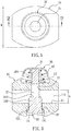
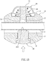
FIG. 13 is also another cross-sectional view showing the operation of the weight assembly according to the preferred embodiment of the present invention. - With reference to
FIG. 1 , aweight assembly 1 for a faucet according to the present invention is fixed on ahose 3 of afaucet 2, and thehose 3 is connected with a spray head 4 so that water sprays out of the spray head 4 via thehose 3. - Referring to
FIGS. 2-7 , theweight assembly 1 includes acounterweight 10, aretainer 20, a pressingmember 30, and aresilient element 40. - The
counterweight 10, as shown inFIGS. 8 and 9 , includes an oval profile, a channel 11 (as illustrated inFIG. 2 ) defined therein in an X-axis direction, wherein a depth d of thechannel 11 in a Y-axis direction is more than 1/2 of a width w of thecounterweight 10 in the Y-axis direction as shown inFIG. 4 , and thechannel 11 has a longitudinal height h defined in a Z-axis direction. - The
channel 11 also has an elongatedfirst opening 111 defined therein, and the longitudinal height h is larger than a diameter of thehose 3, such that thehose 3 can be placed into thechannel 11 as shown inFIG. 11 , and the depth d of thechannel 11 is larger than the diameter of thehose 3 as illustrated inFIG. 4 , such that thehose 3 is accommodated in thechannel 11 completely. In this embodiment, the depth d is 2.5 times of the diameter of thehose 3, but it is not limited by this value, for example, the depth d is at least one 1.5 times of the diameter of thehose 3. - The
channel 11 further has anarcuate fence 112 formed on top end thereof in Y-axis direction, as shown inFIGS. 4 ,8 and12 , to contact with thehose 3. - The
counterweight 10 also includes anon-circular orifice 12 formed on the central position thereof and along the Z-axis direction, wherein the middle section of thenon-circular orifice 12 passes through and communicates with the middle section of thechannel 11, and the diameter of thenon-circular orifice 12 is more than that of the innermost portion of thechannel 11 in the Y-axis direction. - The
counterweight 10 further includes a firstaccommodating cavity 13 defined on top end thereof in the Z-axis direction and a secondaccommodating cavity 14 arranged on bottom end thereof in the Z-axis direction, wherein thenon-circular orifice 12 passes through and extends between the two central portions of the firstaccommodating cavity 13 and the secondaccommodating cavity 14. - The
counterweight 10 is made of metal material or other materials, such as a metal body covered by a rubber layer. - As shown in
FIG. 10 , theretainer 20 is inserted into the secondaccommodating cavity 14, thenon-circular orifice 12 and the firstaccommodating cavity 13 in turn. Theretainer 20 includes anotch 21 arranged on a middle section thereof to define asecond opening 211 facing to thefirst opening 111. Thenotch 21 has an arc-shaped contactingfringe 212 formed on the bottom end thereof and corresponding to the peripheral wall of thehose 3; the longitudinal height h1 of thesecond opening 211 along the Z-axis direction is larger than the diameter of thehose 3, such that thehose 3 can be inserted into thenotch 21 as illustrated inFIGS. 4 ,10 and11 . In this embodiment, the longitudinal height h1 is approximately equal to the longitudinal height h1 of thechannel 11. - The
retainer 20 also includes abase 201, aclamping extension 202 extending upwardly from thebase 201, and acolumn 203 extending upwardly from the clampingextension 202. Thebase 201 is accommodated in the secondaccommodating cavity 14 of thecounterweight 10 and has a stoppingcliff 22 defined thereon to abut against thebottom face 141 of the secondaccommodating cavity 141, as shown inFIG 4 , such that theretainer 20 is limited in it's axial movement by thecounterweight 10. The clampingextension 202 is accommodated in thenon-circular orifice 12 and has thesecond opening 211 defined thereon. Thecolumn 203 is inserted into the first accommodatingcavity 13 to connect with the pressingmember 30. - With reference to
FIGS. 4 and5 , the pressingmember 30 is mounted on top end of thecolumn 203 of theretainer 20 and has apress portion 31 arranged on the outer wall thereof so that a user can press the pressingmember 30. - The
resilient element 40 is defined between the first accommodatingcavity 13 of thecounterweight 10 and the pressingmember 30 to push the pressingmember 30, thereby driving theretainer 20 to move upwardly along the Z-axis direction, such that thehose 3 in thenotch 21 of theretainer 20 is retained between the contactingfringe 212 and thearcuate fence 112 of thechannel 11. - The
resilient element 40 is a compression spring and is fitted on thecolumn 203 of theretainer 20. - The second
accommodating cavity 14 is non-circular; thebase 201 of theretainer 20 is non-circular to correspond to the secondaccommodating cavity 14, such that theretainer 20 can not rotate in thecounterweight 10. - The clamping
extension 202 is non-circular to correspond to thenon-circular orifice 12, such that theretainer 20 can not rotate in thecounterweight 10. - The pressing
member 30 also includes apositioning post 32 extending outwardly from an inner wall thereof, as shown inFIG. 4 , such that a top segment of theresilient element 40 fits with thepositioning post 32. Furthermore, thepositioning post 32 is fitted with the top end of thecolumn 203 of theretainer 20. When theretainer 20 and the pressingmember 30 are made of metal material, thepositioning post 32 is welded with thecolumn 203 of theretainer 20. When theretainer 20 and the pressingmember 30 are made of non-metallic material, thepositioning post 32 is adhered with thecolumn 203 of theretainer 20 by ways of adhesive. Preferably, thepositioning post 32 can be also screwed with thecolumn 203 of theretainer 20. - In operation, the
press portion 31 of the pressingmember 30 is pressed downwardly so that a longitudinal pressing force P produces on the pressingmember 30 along the Z-axis direction to resist against an elasticity of theresilient element 40, and theresilient element 40 is pressed to drive theretainer 20 to move downwardly as illustrated inFIG. 11 , such that thesecond opening 211 of theretainer 20 aligns with thefirst opening 111 of thecounterweight 10, and thehose 3 is inserted into thenotch 21 from thefirst opening 111 through thechannel 11 and thesecond opening 211, thereafter the pressingmember 30 is released so that theresilient element 40 pushes the pressingmember 30 to move upwardly, and the pressingmember 30 and theretainer 20 move upwardly along the Z-axis direction as shown inFIG. 12 , hence thehose 3 is retained between thearcuate fence 112 of thechannel 11 and the contactingfringe 212 of thenotch 21, thus fixing thecounterweight 1 and thehose 3 together. - It is to be noted that the pressing
member 30 is formed in an arcuate cover shape so that when the pressingmember 30 is pressed downwardly, thehose 3 allows inserting through thesecond opening 211. In other words, a bottom end of the pressingmember 30 contacts with a bottom surface of the first accommodatingcavity 13, as shown inFIG. 11 , and thesecond opening 211 aligns with thefirst opening 111, such that thehose 3 is inserted into thenotch 21 easily, and theretainer 20 is controlled accurately. - Referring to
FIG. 10 , after thecounterweight 1 is fixed in thehose 3, thehose 3 is retained between thearcuate fence 112 of thechannel 11 and the contactingfringe 212, thus fixing the thehose 3 and avoiding deformation of thehose 3. - Thereby, the
weight assembly 1 of the present invention has following advantages: - 1. The
hose 3 is fixed easily by pressing and releasing the pressingmember 30. - 2. The
hose 3 is retained at a stable clamping force by using theresilient element 40 to avoid deformation. In other words, the elasticity of theresilient element 40 is controlled easily so that thehose 3 is retained at the stable clamping force. - 3. The
counterweight 1 is packaged firstly and then is unpacked to connect with thehose 3 quickly. - 4. The
counterweight 1 is removed and replaced easily by pressing and releasing the pressingmember 30. - 5. The pressing
member 30 is pressed completely so that thehose 3 is inserted into thenotch 21 of theretainer 20 exactly and quickly. - 6. The
hose 3 is retained between thearcuate fence 112 of thechannel 11 and the contactingfringe 212 and does not deform. - While the preferred embodiments of the invention have been set forth for the purpose of disclosure, modifications of the disclosed embodiments of the invention are possible in the scope of appended claims. The scope of the claims should not be limited by the preferred embodiments set forth in the examples, but should be given the broadest interpretation consistent with the description as a whole.
Claims (10)
- A weight assembly (1) for a faucet (2) having an extendable hose with a spray head, the weight assembly (1) comprising:a counterweight (10) including a channel (11) into which the hose is to be placed in installed state, the channel (11)) being defined in the weight assembly in a X-axis of the weight assembly (1), the channel (11) having an elongated first opening (111) defined therein in a Y-axis direction of the weight assembly, the first opening (111) having a longitudinal height (h1) measured in a Z-axis direction of the weight assembly, the longitudinal height (h1) being larger than the diameter of the hose (3) to be installed in the first opening (111), the depth of the channel (11) measured in the Y-axis direction being larger than the diameter of the hose (3), the hose (3) being in it's installed state accommodated in the channel (11) completely; the counterweight (10) also including an orifice (12) formed on the central position thereof along the Z-axis direction of the weight assembly, the orifice (12) passing through and communicating with the middle section of the channel (11); the counterweight (10) further including a first accommodating cavity (13) defined on the top end thereof in the Z-axis direction of the weight assembly and a second accommodating cavity (14) arranged on the bottom end thereof in the Z-axis direction of the weight assembly, the orifice (12) extending from the first accommodating cavity (13) to the second accommodating cavity (14);a retainer (20) inserted into and extending through the second accommodating cavity (14), the orifice (12), and the first accommodating cavity (13) and including a notch (21) arranged on the middle section thereof to define a second opening (211) facing to the first opening (111) of the counterweight (10); the notch (21) having an arc-shaped contacting fringe (212) formed on the bottom end thereof and corresponding to the peripheral wall of the hose (3); the longitudinal height (h1) of the second opening (211) measured along the Z-axis direction of the weight assembly being larger than the diameter of the hose (3);characterised by
a pressing member (30) mounted on the top end of the retainer (20);
a resilient element (40) arranged between the first accommodating cavity (13) of the counterweight (10) and the pressing member (30) to push the pressing member (30) thereby driving the retainer (20) to move upwardly along the Z-axis direction, such that the hose (3) in it's installed state in the notch (21) of the retainer (20) is retained between the contacting fringe (212) and the channel (11). - The weight assembly (1) as claimed in claim 1, characterized in that the depth of the channel (11) measured in the Y-axis direction of the weight assembly is more than 1/2 of a width of the counterweight (10) in the Y-axis direction, and the depth is at least one 1.5 times of the diameter of the hose (3) used.
- The weight assembly (1) as claimed in claim 2, characterized in that the depth is 2.5 times of the diameter of the hose (3) used.
- The weight assembly (1) as claimed in claim 1, characterized in that the channel (11) further has an arcuate fence (112) formed on the top end thereof in Y-axis direction.
- The weight assembly (1) as claimed in claim 1, characterized in that the retainer (20) also includes a base (201), a clamping extension (202) extending upwardly from the base (201), and a column (203) extending upwardly from the clamping extension (202); the base (201) is accommodated in the second accommodating cavity (14) of the counterweight (10) and has a stopping cliff (22) defined thereon to abut against the bottom face (141) of the second accommodating cavity (14) such that the retainer (20) is limited in it's axial movement by the counterweight (10); the clamping extension (202) is accommodated in the orifice (12) and has the second opening (211) defined thereon; the column (203) is inserted into the first accommodating cavity (13) to connect with the pressing member (30).
- The weight assembly (1) as claimed in claim 5, characterized in that the second accommodating cavity (14) is non-circular in cross-section; the base (201) of the retainer (20) is non-circular in cross-section to correspond to the second accommodating cavity (14), such that the retainer (20) can not rotate in the counterweight (10).
- The weight assembly (1) as claimed in claim 1, characterized in that the orifice (12) is non-circular in cross-section; and the clamping extension (202) is non-circular in cross-section to correspond to the orifice (12), such that the retainer (20) can not rotate in the counterweight (10).
- The weight assembly (1) as claimed in claim 5, characterized in that the resilient element (40) is a compression spring and is fitted on the column (203) of the retainer (20).
- The weight assembly (1) as claimed in claim 8, characterized in that the pressing member (30) also includes a positioning post (32) extending downwardly from the inner wall thereof, such that the top segment of the resilient element (40) fits with the positioning post (32).
- The weight assembly (1) as claimed in claim 5, characterized in that the resilient element (40) is a compression spring and is fitted on the column (203) of the retainer (20); the pressing member (30) has a press portion (31) arranged on the outer wall thereof and a positioning post (32), such that the top segment of the resilient element (40) fits with the positioning post (32), and the positioning post (32) is fitted with the top end of the column (203) of the retainer (20).
Applications Claiming Priority (1)
| Application Number | Priority Date | Filing Date | Title |
|---|---|---|---|
| CN201320664226.2U CN203669026U (en) | 2013-10-25 | 2013-10-25 | Heavy Hammer Assembly |
Publications (2)
| Publication Number | Publication Date |
|---|---|
| EP2865816A1 EP2865816A1 (en) | 2015-04-29 |
| EP2865816B1 true EP2865816B1 (en) | 2018-12-12 |
Family
ID=50965342
Family Applications (1)
| Application Number | Title | Priority Date | Filing Date |
|---|---|---|---|
| EP14190243.7A Active EP2865816B1 (en) | 2013-10-25 | 2014-10-24 | Weight assembly for a faucet having extendable hose with spray head |
Country Status (4)
| Country | Link |
|---|---|
| US (1) | US9145664B2 (en) |
| EP (1) | EP2865816B1 (en) |
| CN (1) | CN203669026U (en) |
| CA (1) | CA2868548C (en) |
Families Citing this family (18)
| Publication number | Priority date | Publication date | Assignee | Title |
|---|---|---|---|---|
| CN203669026U (en) * | 2013-10-25 | 2014-06-25 | 成霖企业股份有限公司 | Heavy Hammer Assembly |
| CN104846971B (en) * | 2014-02-17 | 2016-06-29 | 成霖企业股份有限公司 | A rotary hammer assembly |
| CN105952963B (en) * | 2015-09-22 | 2017-12-29 | 李加庆 | Draw type tap balancing weight |
| CN105782562B (en) * | 2016-05-13 | 2018-11-23 | 厦门构简单工贸有限公司 | A kind of draw type tap clump weight |
| US10161116B2 (en) | 2016-09-21 | 2018-12-25 | Kohler Co. | Kitchen faucet pulldown weight |
| EP3392177B1 (en) * | 2017-04-18 | 2020-06-03 | Cejn Ab | Stop ball |
| US10260216B2 (en) | 2017-08-01 | 2019-04-16 | Xiamen Lota International Co., Ltd. | Pull-out faucet with magnetic docking system |
| CN208430586U (en) * | 2018-04-27 | 2019-01-25 | 成霖企业股份有限公司 | Heavy hammer assembly |
| CN108591238A (en) * | 2018-06-28 | 2018-09-28 | 柳道万和(苏州)热流道系统有限公司 | Flexible axle fixed structure and driving device with it |
| USD954191S1 (en) * | 2020-06-12 | 2022-06-07 | Delta Faucet Company | Faucet |
| CA206748S (en) | 2021-03-31 | 2024-01-05 | Buster & Punch Ltd | Tap |
| USD1046079S1 (en) * | 2021-08-02 | 2024-10-08 | Buster And Punch Limited | Faucet |
| USD1024274S1 (en) * | 2021-09-08 | 2024-04-23 | YUNDA H&H TECH (Tianjin) CO., LTD. | Water faucet |
| USD1024275S1 (en) * | 2021-09-08 | 2024-04-23 | YUNDA H&H TECH (Tianjin) CO., LTD. | Water faucet |
| USD1045021S1 (en) * | 2022-05-30 | 2024-10-01 | Gessi S.P.A. | Faucet |
| USD1079898S1 (en) * | 2022-06-09 | 2025-06-17 | Aquis Systems AG | Water-tap with touch-display |
| CN115233780A (en) * | 2022-06-29 | 2022-10-25 | 箭牌家居集团股份有限公司 | A kind of pipeline stepless adjustment quick assembly weight |
| USD1126361S1 (en) * | 2023-12-28 | 2026-05-12 | Kohler Co. | Faucet |
Family Cites Families (7)
| Publication number | Priority date | Publication date | Assignee | Title |
|---|---|---|---|---|
| US5771934A (en) * | 1994-05-24 | 1998-06-30 | Iw Industries, Inc. | Zinc-based spray faucet hose collar weight |
| US6250338B1 (en) * | 2000-02-29 | 2001-06-26 | Moen Incorporated | Composite faucet hose weight |
| US6460570B1 (en) * | 2001-05-10 | 2002-10-08 | Masco Corporation | Spray faucet hose weight |
| US6915817B2 (en) * | 2003-05-01 | 2005-07-12 | Newfrey Llc | Moveable hose retractor for a pull-out faucet |
| US7143780B1 (en) * | 2004-04-09 | 2006-12-05 | Pitts Christina D | Faucet hose anti-tangling guard for a shut-off valve |
| US8578562B2 (en) * | 2010-08-17 | 2013-11-12 | Globe Union Industrial Corp. | Weight assembly for a hose of a faucet |
| CN203669026U (en) * | 2013-10-25 | 2014-06-25 | 成霖企业股份有限公司 | Heavy Hammer Assembly |
-
2013
- 2013-10-25 CN CN201320664226.2U patent/CN203669026U/en not_active Expired - Lifetime
-
2014
- 2014-10-14 US US14/514,265 patent/US9145664B2/en not_active Expired - Fee Related
- 2014-10-15 CA CA2868548A patent/CA2868548C/en not_active Expired - Fee Related
- 2014-10-24 EP EP14190243.7A patent/EP2865816B1/en active Active
Non-Patent Citations (1)
| Title |
|---|
| None * |
Also Published As
| Publication number | Publication date |
|---|---|
| CA2868548C (en) | 2016-07-05 |
| US20150113767A1 (en) | 2015-04-30 |
| CA2868548A1 (en) | 2015-04-25 |
| US9145664B2 (en) | 2015-09-29 |
| EP2865816A1 (en) | 2015-04-29 |
| CN203669026U (en) | 2014-06-25 |
Similar Documents
| Publication | Publication Date | Title |
|---|---|---|
| US9145664B2 (en) | Weight assembly for a faucet | |
| US7752771B2 (en) | Depth checking device | |
| USD653511S1 (en) | Dispensing tool | |
| US7467575B2 (en) | Replacement assembly of handle tool | |
| JP6754217B2 (en) | A device that connects the inner layer of the helmet to the inner shock absorber of the helmet | |
| US8578562B2 (en) | Weight assembly for a hose of a faucet | |
| US6739572B2 (en) | Timing lock device for a faucet | |
| US8388199B2 (en) | Adjustable lamp device and holding mechanism thereof | |
| US10711936B2 (en) | Weight assembly for a faucet | |
| JP4275112B2 (en) | Level | |
| WO2009011214A1 (en) | Plunger assembly for injector | |
| US20150014371A1 (en) | Gluing nozzle | |
| US9051103B2 (en) | Socket holder | |
| US7565989B2 (en) | Hook device for a nailer | |
| US20180023602A1 (en) | Connection devices for fluidic devices | |
| US8172609B2 (en) | Joint for a cable | |
| CN102909585A (en) | Locking device | |
| CN101305867A (en) | Drawer slide rail fixing device | |
| KR101241417B1 (en) | Gap damper | |
| KR101815201B1 (en) | Cam Slide Unit | |
| CN106320455B (en) | The convenient installing mechanism of tap | |
| CN221984989U (en) | Inner guard ring type spiral clamp spring mounting tool | |
| KR102448678B1 (en) | Prefab unit for shower fixture mounting | |
| JP6125164B2 (en) | Drain plug device | |
| KR101207522B1 (en) | Mounting device of fixing washer for insulating material sheet |
Legal Events
| Date | Code | Title | Description |
|---|---|---|---|
| PUAI | Public reference made under article 153(3) epc to a published international application that has entered the european phase |
Free format text: ORIGINAL CODE: 0009012 |
|
| 17P | Request for examination filed |
Effective date: 20141024 |
|
| AK | Designated contracting states |
Kind code of ref document: A1 Designated state(s): AL AT BE BG CH CY CZ DE DK EE ES FI FR GB GR HR HU IE IS IT LI LT LU LV MC MK MT NL NO PL PT RO RS SE SI SK SM TR |
|
| AX | Request for extension of the european patent |
Extension state: BA ME |
|
| R17P | Request for examination filed (corrected) |
Effective date: 20151005 |
|
| RBV | Designated contracting states (corrected) |
Designated state(s): AL AT BE BG CH CY CZ DE DK EE ES FI FR GB GR HR HU IE IS IT LI LT LU LV MC MK MT NL NO PL PT RO RS SE SI SK SM TR |
|
| GRAP | Despatch of communication of intention to grant a patent |
Free format text: ORIGINAL CODE: EPIDOSNIGR1 |
|
| STAA | Information on the status of an ep patent application or granted ep patent |
Free format text: STATUS: GRANT OF PATENT IS INTENDED |
|
| INTG | Intention to grant announced |
Effective date: 20180509 |
|
| GRAS | Grant fee paid |
Free format text: ORIGINAL CODE: EPIDOSNIGR3 |
|
| GRAA | (expected) grant |
Free format text: ORIGINAL CODE: 0009210 |
|
| STAA | Information on the status of an ep patent application or granted ep patent |
Free format text: STATUS: THE PATENT HAS BEEN GRANTED |
|
| AK | Designated contracting states |
Kind code of ref document: B1 Designated state(s): AL AT BE BG CH CY CZ DE DK EE ES FI FR GB GR HR HU IE IS IT LI LT LU LV MC MK MT NL NO PL PT RO RS SE SI SK SM TR |
|
| REG | Reference to a national code |
Ref country code: GB Ref legal event code: FG4D |
|
| REG | Reference to a national code |
Ref country code: CH Ref legal event code: EP |
|
| REG | Reference to a national code |
Ref country code: AT Ref legal event code: REF Ref document number: 1076150 Country of ref document: AT Kind code of ref document: T Effective date: 20181215 |
|
| REG | Reference to a national code |
Ref country code: DE Ref legal event code: R096 Ref document number: 602014037765 Country of ref document: DE |
|
| REG | Reference to a national code |
Ref country code: IE Ref legal event code: FG4D |
|
| REG | Reference to a national code |
Ref country code: NL Ref legal event code: MP Effective date: 20181212 |
|
| REG | Reference to a national code |
Ref country code: LT Ref legal event code: MG4D |
|
| PG25 | Lapsed in a contracting state [announced via postgrant information from national office to epo] |
Ref country code: BG Free format text: LAPSE BECAUSE OF FAILURE TO SUBMIT A TRANSLATION OF THE DESCRIPTION OR TO PAY THE FEE WITHIN THE PRESCRIBED TIME-LIMIT Effective date: 20190312 Ref country code: LT Free format text: LAPSE BECAUSE OF FAILURE TO SUBMIT A TRANSLATION OF THE DESCRIPTION OR TO PAY THE FEE WITHIN THE PRESCRIBED TIME-LIMIT Effective date: 20181212 Ref country code: FI Free format text: LAPSE BECAUSE OF FAILURE TO SUBMIT A TRANSLATION OF THE DESCRIPTION OR TO PAY THE FEE WITHIN THE PRESCRIBED TIME-LIMIT Effective date: 20181212 Ref country code: HR Free format text: LAPSE BECAUSE OF FAILURE TO SUBMIT A TRANSLATION OF THE DESCRIPTION OR TO PAY THE FEE WITHIN THE PRESCRIBED TIME-LIMIT Effective date: 20181212 Ref country code: LV Free format text: LAPSE BECAUSE OF FAILURE TO SUBMIT A TRANSLATION OF THE DESCRIPTION OR TO PAY THE FEE WITHIN THE PRESCRIBED TIME-LIMIT Effective date: 20181212 Ref country code: ES Free format text: LAPSE BECAUSE OF FAILURE TO SUBMIT A TRANSLATION OF THE DESCRIPTION OR TO PAY THE FEE WITHIN THE PRESCRIBED TIME-LIMIT Effective date: 20181212 Ref country code: NO Free format text: LAPSE BECAUSE OF FAILURE TO SUBMIT A TRANSLATION OF THE DESCRIPTION OR TO PAY THE FEE WITHIN THE PRESCRIBED TIME-LIMIT Effective date: 20190312 |
|
| REG | Reference to a national code |
Ref country code: AT Ref legal event code: MK05 Ref document number: 1076150 Country of ref document: AT Kind code of ref document: T Effective date: 20181212 |
|
| PG25 | Lapsed in a contracting state [announced via postgrant information from national office to epo] |
Ref country code: GR Free format text: LAPSE BECAUSE OF FAILURE TO SUBMIT A TRANSLATION OF THE DESCRIPTION OR TO PAY THE FEE WITHIN THE PRESCRIBED TIME-LIMIT Effective date: 20190313 Ref country code: SE Free format text: LAPSE BECAUSE OF FAILURE TO SUBMIT A TRANSLATION OF THE DESCRIPTION OR TO PAY THE FEE WITHIN THE PRESCRIBED TIME-LIMIT Effective date: 20181212 Ref country code: RS Free format text: LAPSE BECAUSE OF FAILURE TO SUBMIT A TRANSLATION OF THE DESCRIPTION OR TO PAY THE FEE WITHIN THE PRESCRIBED TIME-LIMIT Effective date: 20181212 Ref country code: AL Free format text: LAPSE BECAUSE OF FAILURE TO SUBMIT A TRANSLATION OF THE DESCRIPTION OR TO PAY THE FEE WITHIN THE PRESCRIBED TIME-LIMIT Effective date: 20181212 |
|
| PG25 | Lapsed in a contracting state [announced via postgrant information from national office to epo] |
Ref country code: NL Free format text: LAPSE BECAUSE OF FAILURE TO SUBMIT A TRANSLATION OF THE DESCRIPTION OR TO PAY THE FEE WITHIN THE PRESCRIBED TIME-LIMIT Effective date: 20181212 |
|
| PG25 | Lapsed in a contracting state [announced via postgrant information from national office to epo] |
Ref country code: CZ Free format text: LAPSE BECAUSE OF FAILURE TO SUBMIT A TRANSLATION OF THE DESCRIPTION OR TO PAY THE FEE WITHIN THE PRESCRIBED TIME-LIMIT Effective date: 20181212 Ref country code: PT Free format text: LAPSE BECAUSE OF FAILURE TO SUBMIT A TRANSLATION OF THE DESCRIPTION OR TO PAY THE FEE WITHIN THE PRESCRIBED TIME-LIMIT Effective date: 20190412 Ref country code: PL Free format text: LAPSE BECAUSE OF FAILURE TO SUBMIT A TRANSLATION OF THE DESCRIPTION OR TO PAY THE FEE WITHIN THE PRESCRIBED TIME-LIMIT Effective date: 20181212 |
|
| PG25 | Lapsed in a contracting state [announced via postgrant information from national office to epo] |
Ref country code: SK Free format text: LAPSE BECAUSE OF FAILURE TO SUBMIT A TRANSLATION OF THE DESCRIPTION OR TO PAY THE FEE WITHIN THE PRESCRIBED TIME-LIMIT Effective date: 20181212 Ref country code: IS Free format text: LAPSE BECAUSE OF FAILURE TO SUBMIT A TRANSLATION OF THE DESCRIPTION OR TO PAY THE FEE WITHIN THE PRESCRIBED TIME-LIMIT Effective date: 20190412 Ref country code: SM Free format text: LAPSE BECAUSE OF FAILURE TO SUBMIT A TRANSLATION OF THE DESCRIPTION OR TO PAY THE FEE WITHIN THE PRESCRIBED TIME-LIMIT Effective date: 20181212 Ref country code: EE Free format text: LAPSE BECAUSE OF FAILURE TO SUBMIT A TRANSLATION OF THE DESCRIPTION OR TO PAY THE FEE WITHIN THE PRESCRIBED TIME-LIMIT Effective date: 20181212 Ref country code: RO Free format text: LAPSE BECAUSE OF FAILURE TO SUBMIT A TRANSLATION OF THE DESCRIPTION OR TO PAY THE FEE WITHIN THE PRESCRIBED TIME-LIMIT Effective date: 20181212 |
|
| REG | Reference to a national code |
Ref country code: DE Ref legal event code: R097 Ref document number: 602014037765 Country of ref document: DE |
|
| PLBE | No opposition filed within time limit |
Free format text: ORIGINAL CODE: 0009261 |
|
| STAA | Information on the status of an ep patent application or granted ep patent |
Free format text: STATUS: NO OPPOSITION FILED WITHIN TIME LIMIT |
|
| PG25 | Lapsed in a contracting state [announced via postgrant information from national office to epo] |
Ref country code: AT Free format text: LAPSE BECAUSE OF FAILURE TO SUBMIT A TRANSLATION OF THE DESCRIPTION OR TO PAY THE FEE WITHIN THE PRESCRIBED TIME-LIMIT Effective date: 20181212 Ref country code: SI Free format text: LAPSE BECAUSE OF FAILURE TO SUBMIT A TRANSLATION OF THE DESCRIPTION OR TO PAY THE FEE WITHIN THE PRESCRIBED TIME-LIMIT Effective date: 20181212 Ref country code: DK Free format text: LAPSE BECAUSE OF FAILURE TO SUBMIT A TRANSLATION OF THE DESCRIPTION OR TO PAY THE FEE WITHIN THE PRESCRIBED TIME-LIMIT Effective date: 20181212 |
|
| 26N | No opposition filed |
Effective date: 20190913 |
|
| PG25 | Lapsed in a contracting state [announced via postgrant information from national office to epo] |
Ref country code: TR Free format text: LAPSE BECAUSE OF FAILURE TO SUBMIT A TRANSLATION OF THE DESCRIPTION OR TO PAY THE FEE WITHIN THE PRESCRIBED TIME-LIMIT Effective date: 20181212 |
|
| PG25 | Lapsed in a contracting state [announced via postgrant information from national office to epo] |
Ref country code: MC Free format text: LAPSE BECAUSE OF FAILURE TO SUBMIT A TRANSLATION OF THE DESCRIPTION OR TO PAY THE FEE WITHIN THE PRESCRIBED TIME-LIMIT Effective date: 20181212 |
|
| REG | Reference to a national code |
Ref country code: CH Ref legal event code: PL |
|
| PG25 | Lapsed in a contracting state [announced via postgrant information from national office to epo] |
Ref country code: CH Free format text: LAPSE BECAUSE OF NON-PAYMENT OF DUE FEES Effective date: 20191031 Ref country code: LU Free format text: LAPSE BECAUSE OF NON-PAYMENT OF DUE FEES Effective date: 20191024 Ref country code: LI Free format text: LAPSE BECAUSE OF NON-PAYMENT OF DUE FEES Effective date: 20191031 |
|
| REG | Reference to a national code |
Ref country code: BE Ref legal event code: MM Effective date: 20191031 |
|
| PG25 | Lapsed in a contracting state [announced via postgrant information from national office to epo] |
Ref country code: BE Free format text: LAPSE BECAUSE OF NON-PAYMENT OF DUE FEES Effective date: 20191031 |
|
| GBPC | Gb: european patent ceased through non-payment of renewal fee |
Effective date: 20191024 |
|
| PG25 | Lapsed in a contracting state [announced via postgrant information from national office to epo] |
Ref country code: IE Free format text: LAPSE BECAUSE OF NON-PAYMENT OF DUE FEES Effective date: 20191024 Ref country code: GB Free format text: LAPSE BECAUSE OF NON-PAYMENT OF DUE FEES Effective date: 20191024 |
|
| PG25 | Lapsed in a contracting state [announced via postgrant information from national office to epo] |
Ref country code: CY Free format text: LAPSE BECAUSE OF FAILURE TO SUBMIT A TRANSLATION OF THE DESCRIPTION OR TO PAY THE FEE WITHIN THE PRESCRIBED TIME-LIMIT Effective date: 20181212 |
|
| PG25 | Lapsed in a contracting state [announced via postgrant information from national office to epo] |
Ref country code: HU Free format text: LAPSE BECAUSE OF FAILURE TO SUBMIT A TRANSLATION OF THE DESCRIPTION OR TO PAY THE FEE WITHIN THE PRESCRIBED TIME-LIMIT; INVALID AB INITIO Effective date: 20141024 Ref country code: MT Free format text: LAPSE BECAUSE OF FAILURE TO SUBMIT A TRANSLATION OF THE DESCRIPTION OR TO PAY THE FEE WITHIN THE PRESCRIBED TIME-LIMIT Effective date: 20181212 |
|
| PGFP | Annual fee paid to national office [announced via postgrant information from national office to epo] |
Ref country code: IT Payment date: 20211019 Year of fee payment: 8 Ref country code: FR Payment date: 20211018 Year of fee payment: 8 |
|
| PG25 | Lapsed in a contracting state [announced via postgrant information from national office to epo] |
Ref country code: MK Free format text: LAPSE BECAUSE OF FAILURE TO SUBMIT A TRANSLATION OF THE DESCRIPTION OR TO PAY THE FEE WITHIN THE PRESCRIBED TIME-LIMIT Effective date: 20181212 |
|
| PG25 | Lapsed in a contracting state [announced via postgrant information from national office to epo] |
Ref country code: FR Free format text: LAPSE BECAUSE OF NON-PAYMENT OF DUE FEES Effective date: 20221031 |
|
| PG25 | Lapsed in a contracting state [announced via postgrant information from national office to epo] |
Ref country code: IT Free format text: LAPSE BECAUSE OF NON-PAYMENT OF DUE FEES Effective date: 20221024 |
|
| PGFP | Annual fee paid to national office [announced via postgrant information from national office to epo] |
Ref country code: DE Payment date: 20251027 Year of fee payment: 12 |