EP2865646B1 - Method of producing graphene on a liquid metal - Google Patents
Method of producing graphene on a liquid metal Download PDFInfo
- Publication number
- EP2865646B1 EP2865646B1 EP13005122.0A EP13005122A EP2865646B1 EP 2865646 B1 EP2865646 B1 EP 2865646B1 EP 13005122 A EP13005122 A EP 13005122A EP 2865646 B1 EP2865646 B1 EP 2865646B1
- Authority
- EP
- European Patent Office
- Prior art keywords
- plate
- hpa
- partial pressure
- temperature
- chamber
- Prior art date
- Legal status (The legal status is an assumption and is not a legal conclusion. Google has not performed a legal analysis and makes no representation as to the accuracy of the status listed.)
- Active
Links
Images
Classifications
-
- C—CHEMISTRY; METALLURGY
- C01—INORGANIC CHEMISTRY
- C01B—NON-METALLIC ELEMENTS; COMPOUNDS THEREOF; METALLOIDS OR COMPOUNDS THEREOF NOT COVERED BY SUBCLASS C01C
- C01B32/00—Carbon; Compounds thereof
- C01B32/15—Nano-sized carbon materials
- C01B32/182—Graphene
- C01B32/184—Preparation
- C01B32/186—Preparation by chemical vapour deposition [CVD]
-
- C—CHEMISTRY; METALLURGY
- C01—INORGANIC CHEMISTRY
- C01B—NON-METALLIC ELEMENTS; COMPOUNDS THEREOF; METALLOIDS OR COMPOUNDS THEREOF NOT COVERED BY SUBCLASS C01C
- C01B32/00—Carbon; Compounds thereof
- C01B32/15—Nano-sized carbon materials
- C01B32/182—Graphene
- C01B32/184—Preparation
Definitions
- the present invention relates to a method for producing graphene from a liquid metal.
- Graphene as one of the allotropic forms of carbon, is regarded as the final element of the series of polycyclic aromatic hydrocarbons.
- Graphene is composed of a monolayer of carbon atoms arranged in hexagonal rings which are linked to one another. Since the material is just one-atom thick, the form is referred to as a two-dimensional structure of carbon atoms packed into a hexagonal lattice. The length of the carbon-carbon bonds is ca. 1.42 ⁇ . Carbon atoms in graphene form a flat, practically two-dimensional lattice with hexagonal cells, resembling a honeycomb pattern.
- US2010/0055464 consists in that an eutectic mixture containing pure graphite and a solvent selected from Ni, Cr, Mn, Fe, Co, Ta, Pd, Pt, La and Ce releases, in the process of crystallization, graphite which is then separated into individual graphene layers.
- a graphite disc is placed on a plate made, for example, of pure nickel, heated to 1500°C for 30-60 min, vacuum annealed at a pressure of 1.33 -5 mbar and then cooled down slowly.
- Stacked catalyst layers can be obtained by sputtering, evaporation or the CVD method, or by alternately stacking thin metal films atop one another, followed by annealing.
- the thickness of the layers varies from ca. 10 to ca. 1000 nm.
- hydrocarbons are supplied into the processing chamber containing a previously applied catalyst layer.
- Argon may also be supplied with the hydrocarbons as a carrier gas.
- the ratio of the mixture containing a carbon-carrying gas (usually acetylene) and argon is 1:40.
- the temperature of the substrate can be in the range of 650°C-750°C
- the graphene layer is produced as a result of variable carbon solubility in the catalyst material of the substrate.
- a method which comprises placing a carbon material directly on a catalyst layer which, as a result of heat treatment, undergoes thermal decomposition thus becoming a source of carbon atoms for infiltrating the catalyst layer.
- the carbonaceous material covering the catalyst layer can be a polymer applied to the surface using a variety of coating or immersion methods or other techniques in order to create a uniform layer.
- the thickness of the graphene sheet produced in this manner can be controlled by the molecular weight and the quantity of applied polymer.
- the next stage involves heat treatment in an inert or reducing atmosphere in order to achieve thermal decomposition of the polymer.
- the catalyst layer can be contacted directly with a gaseous carbon source which, according to the patent's claim, can include a compound from the group comprising carbon monoxide, ethane, ethylene, ethanol, acetylene, propane, propylene, butane, butadiene, pentane, pentene, cyclopentadiene, hexane, cyclohexane, benzene, toluene and their combinations. Carbon atoms infiltrate the catalyst layer until the solubility limit is achieved, which is when graphene nucleation occurs and graphene grows forming individual graphene sheets. A significant element of the processes is the cooling method.
- Catalyst layers can have a single-crystal structure and comprise a metal selected from the group consisting of Ni, Co, Fe, Pt, Au, Al, Cr, Cu, Mg, Mn, Mo, Rh, Si, Ta, Ti, W, U, V, Zr or alloys containing at least one of the foregoing metals. Since the catalyst layer is monocrystalline, it resolves the problem of defects which occurs in polycrystalline catalysts.
- the catalyst layer can be used on its own or, as in other methods, disposed on a silicon substrate. The method is suitable for producing between 1 and ca. 300 layers, each single layer measuring between ca. 1 mm and ca. 1000 mm.
- Yet another method disclosed in the patent application No. US 2010/0255984 involves the process of carbonization of ruthenium (Ru) as a mono- or polycrystalline substrate deposited epitaxially with a plane (0001) having a hexagonal crystalline structure matched to that of the emerging graphene.
- the substrate is heated to a temperature of ca. 0.5 Ttop., under reduced pressure, maintained at that temperature for several up to several dozen seconds, and then annealed in an atmosphere of ethylene at 10 -5 mbar, following which Ru is cooled down to a temperature of 0.3-0.4 Ttop. at a rate of 20°C/min or lower.
- the patent description No. US 2011/0033688 discloses the process of graphene growth from a gaseous phase containing acetylene or methane with argon (as a carrier gas).
- the catalyst is a thin layer of metal, suitable metals including nickel, cobalt, iron, copper or metal alloys (e.g. iron-nickel, nickel-chromium) applied to the substrate.
- the catalyst layer has an oriented polycrystalline structure with large grains, ca. 10 ⁇ m in size.
- the process involves the stage of heating the substrate to 800-900°C in a carbon-rich atmosphere at a pressure of 5-150 mbar, followed by sudden cooling. Cooling is performed with an inert gas, to the temperature level of 700°C or lower.
- EP 2 392 547 is a method based on graphene growth from the gaseous phase on a SiC (silicon carbide) substrate, characterized in that the process of silicon sublimation from the substrate is controlled with the flow of an inert gas - argon (or a gas other than inert) through the epitaxial reactor.
- the flow rate of the inert gas ranges from 6 l/min (or less) to 70 l/min, at a pressure of 10 -4 mbar.
- the substrate becomes heated to over 1100°C during the process.
- the epitaxy is preceded by a stage of etching in the atmosphere of gas containing hydrogen. It may also additionally contain propane, silane or their mixtures, or other hydrocarbons.
- the process is conducted at various temperatures within the 1400°C-2000°C range and at a pressure of 10-1000 mbar.
- the patent description No. US 2011/0206934 presents a method for producing an appropriate multilayered structure, with one of the layers constituting a source of carbon atoms.
- the substrate is composed of silicon coated with silica, to which amorphous carbon is applied by ion sputtering, and then hydrogenated.
- the layer comprises a metal-carbon alloy containing at least 50 atomic percent of carbon, and has a thickness in the range from 0.5 nm to 50 nm.
- a second layer composed of a metal (Co, Cu, Fe, Ir, Mo, Ni, Pd, Pt, Ru or their alloys), between 10 and 1000 nm thick, is applied to the first layer, e.g. using the PVD method.
- the multilayered structure is then annealed at the temperature range of 550°C-1400°C in the atmosphere of Ar/H 2 and N 2 /H 2 , N 2 , Ar, He or in a vacuum. In this way, carbon infiltrates the metal layer, leading to the deposition of graphene.
- the essence of the graphene production method according to the present invention consists in that a multilayered plate containing, as the graphene forming matrix, an external layer composed of a metal or a metal alloy with a melting point in the range from 1051°C and 1150°C and, as a substrate, between 1 and 5 layers made of transition metals and/or their alloys and/or metalloids and/or their solutions and compounds with melting points in the range from 1151°C to 3410°C is heated, as the first stage, until the plate reaches a temperature that is between 0.5°C and 50°C higher than the melting point of the forming matrix, at which point, as the second stage, it is annealed at a constant or variable temperature from the same range for a period ranging from 60 to 600 seconds, with a concurrent supply of gases into the atmosphere - acetylene at a partial pressure of between 0 and 4 hPa, ethylene at a partial pressure of between 0 and 4 hPa and hydrogen at a partial pressure of between
- the external metal layer is made of copper.
- the graphene-forming external layer composed of a metal or a metal alloy is also advantageous for the graphene-forming external layer composed of a metal or a metal alloy to be between 500 and 500000 nm thick.
- transition metals are selected from the group comprising platinum, palladium and nickel.
- the metalloids or their compounds are selected from silicon or quartz.
- the platinum plate which is at least 0.2 mm thick and coated by electrolysis on one side with a 0.2 mm thick copper layer, is placed in the chamber of a vacuum furnace, at which point, after removing air from the chamber to the vacuum level of 10 -3 hPa, argon is supplied into the furnace chamber in such a way as to maintain the partial pressure of argon throughout the entire process at the level of 20 hPa, whereby concurrently with the commencement of argon supply the plate heating process is initiated and continued until the plate reaches 1100°C and the temperature of the plate stabilizes at this level for 2.5 min, with acetylene, ethylene, hydrogen and argon additionally supplied into the furnace chamber for 60 seconds during the period of maintaining constant temperatures until the partial pressure reaches 28 hPa, following which the plate is cooled down at a rate of 1°C/min to 1075°C, at which point rapid uncontrolled cooling to the ambient temperature is continued in the furnace chamber.
- a molybdenum plate with a thickness of 4.5 mm and dimensions of 50x50 mm is coated by magnetron sputtering with a 40 ⁇ m thick layer of nickel and then a 1.5 mm thick layer of copper and is placed in the chamber of a vacuum furnace, at which point, after removing air from the chamber to the vacuum level of 10 -3 hPa, argon is supplied into the furnace chamber in such a way as to maintain the partial pressure of argon throughout the entire process at the level of 1100hPa, whereby at the same time the plate heating process is initiated and continued until the plate reaches 1100°C and then temperature of the plate stabilizes at this level for 10 minutes, with additional hydrogen supplied into the furnace chamber for 120 seconds during the period of heating to the temperature to achieve the partial pressure of 60hPa, following which the plate is cooled down at a rate of 0.2°C/min to 1050°C, at which point rapid uncontrolled cooling to the ambient temperature is continued in the furnace chamber.
- the quartz glass plate which is at least 0.8 mm thick and coated with a 300 nm thick layer of silicon and a 1000 nm thick layer of copper, is placed in the chamber of a vacuum furnace, at which point, after removing air from the chamber to the vacuum level of 10 -3 hPa, argon is supplied into the furnace chamber in such a way as to maintain the partial pressure of argon throughout the entire process at the level of 50 hPa, whereby after 5 minutes the plate heating process is initiated and continued until the plate reaches 1090°C and the temperature of the plate stabilizes at this level for 5 minutes, with additional gases supplied into the furnace chamber for 20 seconds during the period of maintaining constant temperature, including acetylene - to achieve the partial pressure of 2 hPa, ethylene - to reach the partial pressure of 2 hPa and hydrogen - to attain the partial pressure of 1 hPa, following which the plate is cooled down at a rate of 0.2°C/min to 1075°C, at which point
- the two-layer plate thus prepared was placed in the chamber of a vacuum furnace, following which air was removed from the chamber to achieve the vacuum level of 10 -3 hPa.
- argon was supplied into the furnace chamber to maintain the partial pressure of argon at the level of 20 hPa throughout the entire process. Concurrently with the commencement of argon supply into the chamber the process of plate heating was initiated and maintained until the temperature reached 1100°C, at which point the temperature of the plate was stabilized at this level for 2.5 min.
- acetylene, ethylene, hydrogen and argon were additionally supplied into the furnace chamber for 60 seconds until the partial pressure of 28 hPa was attained.
- the plate cooling process was then commenced, at a rate of 1°C/min, to the temperature of 1075°C, followed by rapid uncontrolled cooling to the ambient temperature in the furnace chamber.
- a polycrystalline monolayer of graphene with a grain size ranging from 100 to 120 ⁇ m was ultimately identified on the copper surface.
- a polymethyl methacrylate film was attached to the surface of the plate and copper was selectively etched from the space between platinum and PMTM, producing a polycrystalline graphene sheet measuring 10 x 40 mm.
- the three-layer plate thus prepared was placed in the chamber of a vacuum furnace, following which air was removed from the chamber to achieve the vacuum level of 10 -3 hPa.
- argon was supplied into the furnace chamber to maintain the partial pressure of argon at the level of 1100 hPa throughout the entire process.
- the process of plate heating was initiated and maintained until the temperature reached 1100°C, at which point the temperature of the plate was stabilized at this level for 10 minutes.
- the three-layer plate thus prepared was placed in the chamber of a vacuum furnace, following which air was removed from the chamber to achieve the vacuum level of 10 -3 hPa.
- argon was supplied into the furnace chamber to maintain the partial pressure of argon at the level of 50 hPa throughout the entire process. After 5 minutes the process of plate heating was initiated and maintained until the temperature reached 1090°C, at which point the temperature of the plate was stabilized at this level for 5 minutes.
- a polymethyl methacrylate film was attached to the surface of the plate and flat pressure was exerted on the plate to crush the quartz glass substrate, following which copper was solubilized in 1N nitric acid.
- a polycrystalline graphene sheet measuring 15 x 40 mm was obtained in the process.
Landscapes
- Chemical & Material Sciences (AREA)
- Organic Chemistry (AREA)
- Engineering & Computer Science (AREA)
- Materials Engineering (AREA)
- Nanotechnology (AREA)
- Inorganic Chemistry (AREA)
- Carbon And Carbon Compounds (AREA)
Description
- This application relies on the Polish Patent Application No.
P.399096, filed May 04, 2012 - The present invention relates to a method for producing graphene from a liquid metal.
- Graphene, as one of the allotropic forms of carbon, is regarded as the final element of the series of polycyclic aromatic hydrocarbons. Graphene is composed of a monolayer of carbon atoms arranged in hexagonal rings which are linked to one another. Since the material is just one-atom thick, the form is referred to as a two-dimensional structure of carbon atoms packed into a hexagonal lattice. The length of the carbon-carbon bonds is ca. 1.42 Å. Carbon atoms in graphene form a flat, practically two-dimensional lattice with hexagonal cells, resembling a honeycomb pattern.
- There are known graphene production methods which make use of the liquid state for graphene formation but are not based on the variable decreasing solubility of carbon in the liquid state. The method outlined in the patent application No.
US 2012/0082787 relates to the formation of a graphene layer using liquid gallium. According to the method, an amorphous carbon film produced by vapour-depositing on an organic film is then transferred to a substrate of liquid gallium (or, alternatively, indium, tin or antimony), forming a graphene layer as a result of the graphitization reaction arising at the contact interface between the solid phase and the liquid phase. The other known method, presented in the patent description No.US2010/0055464 , consists in that an eutectic mixture containing pure graphite and a solvent selected from Ni, Cr, Mn, Fe, Co, Ta, Pd, Pt, La and Ce releases, in the process of crystallization, graphite which is then separated into individual graphene layers. To this aim, a graphite disc is placed on a plate made, for example, of pure nickel, heated to 1500°C for 30-60 min, vacuum annealed at a pressure of 1.33-5 mbar and then cooled down slowly. - Known are also methods based on the epitaxial growth of graphene from the gaseous phase on substrates composed of metals, alloys and intermetallic phases with mono- or polycrystalline structures. The transport of carbon into the graphene layer often makes use of the variable solubility of carbon, decreasing along with temperature, in the solid state forming matrix.
- Known from the patent description No.
US 2011/0108609 is a method of fabricating graphene in which a layer including nickel (Ni) or a nickel-based alloy containing at least one metal from the group comprising copper (Cu), iron (Fe), gold (Au) and platinum (Pt) is saturated with carbon. Nickel-based alloys contain between 5 and 30 atomic % of Ni. The role of alloy additives is to restrict the solubility of carbon in Ni. The catalyst layer is applied in the process of evaporation to a silicon substrate coated with silica (SiO2/Si). Stacked catalyst layers can be obtained by sputtering, evaporation or the CVD method, or by alternately stacking thin metal films atop one another, followed by annealing. The thickness of the layers varies from ca. 10 to ca. 1000 nm. In order to produce a graphene layer, hydrocarbons are supplied into the processing chamber containing a previously applied catalyst layer. Argon may also be supplied with the hydrocarbons as a carrier gas. The ratio of the mixture containing a carbon-carrying gas (usually acetylene) and argon is 1:40. During the formation of the graphene layer the temperature of the substrate can be in the range of 650°C-750°C The graphene layer is produced as a result of variable carbon solubility in the catalyst material of the substrate. - Known from the patent description No.
US 2009/0155561 is a method which comprises placing a carbon material directly on a catalyst layer which, as a result of heat treatment, undergoes thermal decomposition thus becoming a source of carbon atoms for infiltrating the catalyst layer. The carbonaceous material covering the catalyst layer can be a polymer applied to the surface using a variety of coating or immersion methods or other techniques in order to create a uniform layer. The thickness of the graphene sheet produced in this manner can be controlled by the molecular weight and the quantity of applied polymer. The next stage involves heat treatment in an inert or reducing atmosphere in order to achieve thermal decomposition of the polymer. As an alternative to placing a carbonaceous material on the surface of the catalyst layer, the catalyst layer can be contacted directly with a gaseous carbon source which, according to the patent's claim, can include a compound from the group comprising carbon monoxide, ethane, ethylene, ethanol, acetylene, propane, propylene, butane, butadiene, pentane, pentene, cyclopentadiene, hexane, cyclohexane, benzene, toluene and their combinations. Carbon atoms infiltrate the catalyst layer until the solubility limit is achieved, which is when graphene nucleation occurs and graphene grows forming individual graphene sheets. A significant element of the processes is the cooling method. Catalyst layers can have a single-crystal structure and comprise a metal selected from the group consisting of Ni, Co, Fe, Pt, Au, Al, Cr, Cu, Mg, Mn, Mo, Rh, Si, Ta, Ti, W, U, V, Zr or alloys containing at least one of the foregoing metals. Since the catalyst layer is monocrystalline, it resolves the problem of defects which occurs in polycrystalline catalysts. The catalyst layer can be used on its own or, as in other methods, disposed on a silicon substrate. The method is suitable for producing between 1 and ca. 300 layers, each single layer measuring between ca. 1 mm and ca. 1000 mm. - Yet another method disclosed in the patent application No.
US 2010/0255984 involves the process of carbonization of ruthenium (Ru) as a mono- or polycrystalline substrate deposited epitaxially with a plane (0001) having a hexagonal crystalline structure matched to that of the emerging graphene. According to the method, the substrate is heated to a temperature of ca. 0.5 Ttop., under reduced pressure, maintained at that temperature for several up to several dozen seconds, and then annealed in an atmosphere of ethylene at 10-5 mbar, following which Ru is cooled down to a temperature of 0.3-0.4 Ttop. at a rate of 20°C/min or lower. - The patent description No.
US 2011/0033688 discloses the process of graphene growth from a gaseous phase containing acetylene or methane with argon (as a carrier gas). Similarly to the methods reported above, the catalyst is a thin layer of metal, suitable metals including nickel, cobalt, iron, copper or metal alloys (e.g. iron-nickel, nickel-chromium) applied to the substrate. The catalyst layer has an oriented polycrystalline structure with large grains, ca. 10 µm in size. The process involves the stage of heating the substrate to 800-900°C in a carbon-rich atmosphere at a pressure of 5-150 mbar, followed by sudden cooling. Cooling is performed with an inert gas, to the temperature level of 700°C or lower. - Known from the patent description No.
EP 2 392 547 is a method based on graphene growth from the gaseous phase on a SiC (silicon carbide) substrate, characterized in that the process of silicon sublimation from the substrate is controlled with the flow of an inert gas - argon (or a gas other than inert) through the epitaxial reactor. The flow rate of the inert gas ranges from 6 l/min (or less) to 70 l/min, at a pressure of 10-4 mbar. The substrate becomes heated to over 1100°C during the process. The epitaxy is preceded by a stage of etching in the atmosphere of gas containing hydrogen. It may also additionally contain propane, silane or their mixtures, or other hydrocarbons. The process is conducted at various temperatures within the 1400°C-2000°C range and at a pressure of 10-1000 mbar. - The patent description No.
US 2011/0206934 presents a method for producing an appropriate multilayered structure, with one of the layers constituting a source of carbon atoms. The substrate is composed of silicon coated with silica, to which amorphous carbon is applied by ion sputtering, and then hydrogenated. Alternatively, the layer comprises a metal-carbon alloy containing at least 50 atomic percent of carbon, and has a thickness in the range from 0.5 nm to 50 nm. As the next stage, a second layer composed of a metal (Co, Cu, Fe, Ir, Mo, Ni, Pd, Pt, Ru or their alloys), between 10 and 1000 nm thick, is applied to the first layer, e.g. using the PVD method. The multilayered structure is then annealed at the temperature range of 550°C-1400°C in the atmosphere of Ar/H2 and N2/H2, N2, Ar, He or in a vacuum. In this way, carbon infiltrates the metal layer, leading to the deposition of graphene. - D. Geng et al, in their the publication of "Uniform hexagonal grapheme flakes and films grown on liquid copper surface", PROCEEDINGS OF THE NATIONAL ACADEMY OF SCIENCES, vol. 109, no.21, 22 May 2012 (2012-05-22), pages 7992-7996, XP055064478, ISSN: 0027-8424, DOI: 10.1073/pnas. 1200339109; & D. GENG ET AL: "Supporting Information: Uniform haexagonal graphene flakes and films grown on liquid copper surface", "PROCEEDINGS OF THE NATIONAL ACADEMY OF SCIENCES, vol. 109, no.21, 16 April 2012 (2012-04-16), XP055104332, ISSN: 0027-8424, DOI; 10.1073/pnas. 1200339109, in
Fig. 2 and in section "Methods" and "Supporting Informations", teach a method of producing a grapheme layer from a liquid metal (copper) matrix on a solid metal (tungsten) substrate, wherein a multilayered plate containing as the grapheme forming matrix, an external layer composed of a metal (copper) with a melting point of 1085°C which is in the range from 1051°C and 1150°C, and as a support substrate, one layer made of transition metal (tungsten) with a melting point of 3410°C, which is in the range from 1151 °C to 3410°C, is subjected to heat treatment in the following stages: - heating the plate to a temperature of 1120°C that is between 0.5°C and 50°C higher than the melting point of the forming matrix (copper),
- annealing, at a constant temperature for a period of 1800 seconds and supplying methane and hydrogen for 1080 seconds,
- cooling down to room temperature with a cooling rate of 25°C/min.
- In turn, the paper of P. Kula et al: "The growth of a polycrystalline graphene from a liquid phase", NANOTECH CONFERENCE & EXPO 2013: AN INTERDISCIPLINARY INTEGRATIVE FORUM ON NANOTECHNOLOGY, MICROTECHNOLOGY, BIOTECHNOLOGY AND CLEANTECHNOLOGY; WASHINGTON, DC, UNITED STATES; MAY 12-16, 2013, CRS PRESS, BOCARATON, FLA, USA, Vol. 1, 12 May 2013 (2013-05-12), - 16 May 2013 (2013-05-16), pages 210-212, XP008167821, ISBN: 978-1-4822-0579-4 discloses the method of producing graphene from liquid metal with using the mixture of acetylene, ethylene and hydrogen as carburising medium in the temperature 1200°C-1250°C The monolithic plate of cooper-nickel was used as a substrate for the deposition of grapheme. However, this method limits the ability to transfer carbon and thus prevents its precise dosing.
- The essence of the graphene production method according to the present invention consists in that a multilayered plate containing, as the graphene forming matrix, an external layer composed of a metal or a metal alloy with a melting point in the range from 1051°C and 1150°C and, as a substrate, between 1 and 5 layers made of transition metals and/or their alloys and/or metalloids and/or their solutions and compounds with melting points in the range from 1151°C to 3410°C is heated, as the first stage, until the plate reaches a temperature that is between 0.5°C and 50°C higher than the melting point of the forming matrix, at which point, as the second stage, it is annealed at a constant or variable temperature from the same range for a period ranging from 60 to 600 seconds, with a concurrent supply of gases into the atmosphere - acetylene at a partial pressure of between 0 and 4 hPa, ethylene at a partial pressure of between 0 and 4 hPa and hydrogen at a partial pressure of between 0 and 2 hPa, for 10-300 seconds, whereupon, as the third stage, the plate is cooled down maintaining the cooling rate of 0.1-2°C/min within the temperature range from 1200°C to 1050°C, where consecutive stages of heating, annealing and cooling are performed in the atmosphere of pure argon at a constant partial pressure varying from 1 hPa to 1100 hPa.
- Advantageously, the external metal layer is made of copper.
- It is also advantageous for the graphene-forming external layer composed of a metal or a metal alloy to be between 500 and 500000 nm thick.
- It is furthermore advantageous than the transition metals are selected from the group comprising platinum, palladium and nickel.
- It is also advantageous that the metalloids or their compounds are selected from silicon or quartz.
- In particular, it is advantageous that the platinum plate, which is at least 0.2 mm thick and coated by electrolysis on one side with a 0.2 mm thick copper layer, is placed in the chamber of a vacuum furnace, at which point, after removing air from the chamber to the vacuum level of 10-3 hPa, argon is supplied into the furnace chamber in such a way as to maintain the partial pressure of argon throughout the entire process at the level of 20 hPa, whereby concurrently with the commencement of argon supply the plate heating process is initiated and continued until the plate reaches 1100°C and the temperature of the plate stabilizes at this level for 2.5 min, with acetylene, ethylene, hydrogen and argon additionally supplied into the furnace chamber for 60 seconds during the period of maintaining constant temperatures until the partial pressure reaches 28 hPa, following which the plate is cooled down at a rate of 1°C/min to 1075°C, at which point rapid uncontrolled cooling to the ambient temperature is continued in the furnace chamber.
- In particular, it is likewise advantageous that a molybdenum plate with a thickness of 4.5 mm and dimensions of 50x50 mm is coated by magnetron sputtering with a 40µm thick layer of nickel and then a 1.5 mm thick layer of copper and is placed in the chamber of a vacuum furnace, at which point, after removing air from the chamber to the vacuum level of 10-3hPa, argon is supplied into the furnace chamber in such a way as to maintain the partial pressure of argon throughout the entire process at the level of 1100hPa, whereby at the same time the plate heating process is initiated and continued until the plate reaches 1100°C and then temperature of the plate stabilizes at this level for 10 minutes, with additional hydrogen supplied into the furnace chamber for 120 seconds during the period of heating to the temperature to achieve the partial pressure of 60hPa, following which the plate is cooled down at a rate of 0.2°C/min to 1050°C, at which point rapid uncontrolled cooling to the ambient temperature is continued in the furnace chamber.
- In particular, it is also advantageous that the quartz glass plate, which is at least 0.8 mm thick and coated with a 300 nm thick layer of silicon and a 1000 nm thick layer of copper, is placed in the chamber of a vacuum furnace, at which point, after removing air from the chamber to the vacuum level of 10-3 hPa, argon is supplied into the furnace chamber in such a way as to maintain the partial pressure of argon throughout the entire process at the level of 50 hPa, whereby after 5 minutes the plate heating process is initiated and continued until the plate reaches 1090°C and the temperature of the plate stabilizes at this level for 5 minutes, with additional gases supplied into the furnace chamber for 20 seconds during the period of maintaining constant temperature, including acetylene - to achieve the partial pressure of 2 hPa, ethylene - to reach the partial pressure of 2 hPa and hydrogen - to attain the partial pressure of 1 hPa, following which the plate is cooled down at a rate of 0.2°C/min to 1075°C, at which point rapid uncontrolled cooling to the ambient temperature is continued in the furnace chamber.
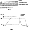
- The invention will be described in more detail below in conjunction with examples and a drawing in which individual figures illustrate:
-
Fig. 1 - cross-section of the structure of a multi-layer plate containing a graphene-forming matrix in the form of an outer layer consisting of a metal or a metal alloy and a support substrate layer, and -
Fig. 2 - diagram illustrating consecutive steps of the thermal process and gas supply. - A platinum plate, 0.3 mm thick and measuring 10x40 mm, was coated by electrolysis on one side with a 0.2 mm thick layer of copper. The two-layer plate thus prepared was placed in the chamber of a vacuum furnace, following which air was removed from the chamber to achieve the vacuum level of 10-3 hPa. As the next step, argon was supplied into the furnace chamber to maintain the partial pressure of argon at the level of 20 hPa throughout the entire process. Concurrently with the commencement of argon supply into the chamber the process of plate heating was initiated and maintained until the temperature reached 1100°C, at which point the temperature of the plate was stabilized at this level for 2.5 min. As the temperature was maintained at a constant level, acetylene, ethylene, hydrogen and argon were additionally supplied into the furnace chamber for 60 seconds until the partial pressure of 28 hPa was attained. The plate cooling process was then commenced, at a rate of 1°C/min, to the temperature of 1075°C, followed by rapid uncontrolled cooling to the ambient temperature in the furnace chamber. A polycrystalline monolayer of graphene with a grain size ranging from 100 to 120 µm was ultimately identified on the copper surface. A polymethyl methacrylate film was attached to the surface of the plate and copper was selectively etched from the space between platinum and PMTM, producing a polycrystalline graphene sheet measuring 10 x 40 mm.
- A molybdenum plate, 4,5 mm thick and measuring 50x50 mm, was coated by magnetron sputtering with a 40µm thick layer of nickel, followed by a 1.5 mm thick layer of copper. The three-layer plate thus prepared was placed in the chamber of a vacuum furnace, following which air was removed from the chamber to achieve the vacuum level of 10-3 hPa. As the next step, argon was supplied into the furnace chamber to maintain the partial pressure of argon at the level of 1100 hPa throughout the entire process. At the same time the process of plate heating was initiated and maintained until the temperature reached 1100°C, at which point the temperature of the plate was stabilized at this level for 10 minutes. While heating to the temperature additional hydrogen was supplied into the furnace chamber for 120 seconds to achieve the partial pressure of 60 hPa. The plate cooling process was then commenced, at a rate of 0.2°C/min, to the temperature of 1050°C, followed by rapid uncontrolled cooling to the ambient temperature in the furnace chamber. A polycrystalline monolayer of graphene with a grain size ranging from 100 to 120 µm was ultimately identified on the copper surface. A polymethyl methacrylate film was attached to the surface of the plate and copper was selectively etched from the space between platinum and PMTM, producing a polycrystalline graphene sheet measuring 40 x 40 mm.
- A plate of quartz glass, 2 mm thick and measuring 15x40 mm, was coated by magnetron sputtering with a 300 nm thick layer of silicon, followed by a 1000 nm thick layer of copper. The three-layer plate thus prepared was placed in the chamber of a vacuum furnace, following which air was removed from the chamber to achieve the vacuum level of 10-3 hPa. As the next step, argon was supplied into the furnace chamber to maintain the partial pressure of argon at the level of 50 hPa throughout the entire process. After 5 minutes the process of plate heating was initiated and maintained until the temperature reached 1090°C, at which point the temperature of the plate was stabilized at this level for 5 minutes. As the temperature was maintained at a constant level, additional gases were supplied into the furnace chamber for 20 seconds: acetylene - to achieve the partial pressure of 2 hPa, ethylene - to reach the partial pressure of 2 hPa and hydrogen - to attain the partial pressure of 1 hPa. The plate cooling process was then commenced, at a rate of 0.2°C/min, to the temperature of 1075°C, followed by rapid uncontrolled cooling to the ambient temperature in the furnace chamber. A polycrystalline monolayer of graphene with a grain size ranging from 200 to 220 µm was ultimately identified on the copper surface. A polymethyl methacrylate film was attached to the surface of the plate and flat pressure was exerted on the plate to crush the quartz glass substrate, following which copper was solubilized in 1N nitric acid. A polycrystalline graphene sheet measuring 15 x 40 mm was obtained in the process.
Claims (8)
- A method for producing a graphene layer from a liquid metal matrix on a solid metal or ceramic substrate with using the mixture of acetylene, ethylene and hydrogen as a carburising medium, characterized in that a multilayered plate containing, as the graphene forming matrix, an external layer composed of a metal or a metal alloy with a melting point in the range from 1051°C and 1150°C and, as a support substrate, between 1 and 5 layers made of transition metals and/or their alloys and/or metalloids and/or their solutions and compounds with melting points in the range from 1151°C to 3410°C, is subjected to heat treatment in the following stages:- plate heating until the plate reaches a temperature that is between 0.5°C and 50°C higher than the melting point of the forming matrix,- annealing, at a constant or variable temperature from the temperature range, for a period between 60 and 600 seconds, concurrently supplying the atmosphere with acetylene at a partial pressure of between 0 and 4 hPa, ethylene at a partial pressure of between 0 and 4 hPa and hydrogen at a partial pressure of between 0 and 2 hPa for a period between 10 and 300 seconds,- cooling, partially controlled, with the cooling rate maintained between 0.1 and 2°C/min in the temperature range of 1200°C-1050°C, where consecutive stages of heating, annealing and cooling are conducted in the atmosphere of pure argon at a constant partial pressure varying from 1 hPa to 1100 hPa.
- The method according to claim 1, characterized in that the external metal layer is made of copper.
- The method according to claim 1 or 2, characterized in that the graphene-forming external layer of metal or metal alloy is between 500 and 500 000 nm thick.
- The method according to claim 1 or 2 or 3, characterized in that platinum and/or molybdenum and/or palladium and/or nickel are used as the transition metals.
- The method according to claim 1 or 2 or 3, characterized in that silicon or quartz are used as the metalloids or their compounds.
- The method according to claim 4, characterized in that the platinum plate, which is at least 0.2 mm thick and coated by electrolysis on one side with a 0.2 mm thick copper layer, is placed in the chamber of a vacuum furnace, at which point, after removing air from the chamber to the vacuum level of 10-3 hPa, argon is supplied into the furnace chamber in such a way as to maintain the partial pressure of argon throughout the entire process at the level of 20 hPa, whereby concurrently with the commencement of argon supply the plate heating process is initiated and continued until the plate reaches 1100°C and the temperature of the plate stabilizes at this level for 2.5 min, with acetylene, ethylene, hydrogen and argon additionally supplied into the furnace chamber for 60 seconds during the period of maintaining constant temperature until the partial pressure reaches 28 hPa, following which the plate is cooled down at a rate of 1°C/min to 1075°C, at which point rapid uncontrolled cooling to the ambient temperature is continued in the furnace chamber.
- The method according to claims 4, characterized in that a molybdenum plate with a thickness of 4.5 mm and dimensions of 50x50 mm is coated by magnetron sputtering with a 40µm thick layer of nickel and then a 1.5 mm thick layer of copper and is placed in the chamber of a vacuum furnace, at which point, after removing air from the chamber to the vacuum level of 10-3hPa, argon is supplied into the furnace chamber in such a way as to maintain the partial pressure of argon throughout the entire process at the level of 1100hPa, whereby at the same time the plate heating process is initiated and continued until the plate reaches 1100°C and then temperature of the plate stabilizes at this level for 10 minutes, with additional hydrogen supplied into the furnace chamber for 120 seconds during the period of heating to the temperature to achieve the partial pressure of 60hPa, following which the plate is cooled down at a rate of 0.2°C/min to 1050°C, at which point rapid uncontrolled cooling to the ambient temperature is continued in the furnace chamber.
- The method according to claim 5, characterized in that a quartz glass plate, which is at least 0.8 mm thick and coated with a 300 nm thick layer of silicon and a 1000 nm thick layer of copper, is placed in the chamber of a vacuum furnace, at which point, after removing air from the chamber to the vacuum level of 10-3 hPa, argon is supplied into the furnace chamber in such a way as to maintain the partial pressure of argon throughout the entire process at the level of 50 hPa, whereby after 5 minutes the plate heating process is initiated and continued until the plate reaches 1090°C and the temperature of the plate stabilizes at this level for 5 minutes, with additional gases supplied into the furnace chamber for 20 seconds during the period of maintaining constant temperature: acetylene - to achieve the partial pressure of 2 hPa, ethylene - to reach the partial pressure of 2 hPa and hydrogen - to attain the partial pressure of 1 hPa, following which the plate is cooled down at a rate of 0.2°C/min to 1075°C, at which point rapid uncontrolled cooling to the ambient temperature is continued in the furnace chamber.
Priority Applications (2)
| Application Number | Priority Date | Filing Date | Title |
|---|---|---|---|
| EP13005122.0A EP2865646B8 (en) | 2013-10-28 | 2013-10-28 | Method of producing graphene on a liquid metal |
| ES13005122.0T ES2589793T3 (en) | 2013-10-28 | 2013-10-28 | Graphene production procedure on a liquid metal |
Applications Claiming Priority (1)
| Application Number | Priority Date | Filing Date | Title |
|---|---|---|---|
| EP13005122.0A EP2865646B8 (en) | 2013-10-28 | 2013-10-28 | Method of producing graphene on a liquid metal |
Publications (3)
| Publication Number | Publication Date |
|---|---|
| EP2865646A1 EP2865646A1 (en) | 2015-04-29 |
| EP2865646B1 true EP2865646B1 (en) | 2016-06-08 |
| EP2865646B8 EP2865646B8 (en) | 2016-07-27 |
Family
ID=49509915
Family Applications (1)
| Application Number | Title | Priority Date | Filing Date |
|---|---|---|---|
| EP13005122.0A Active EP2865646B8 (en) | 2013-10-28 | 2013-10-28 | Method of producing graphene on a liquid metal |
Country Status (2)
| Country | Link |
|---|---|
| EP (1) | EP2865646B8 (en) |
| ES (1) | ES2589793T3 (en) |
Cited By (2)
| Publication number | Priority date | Publication date | Assignee | Title |
|---|---|---|---|---|
| CN108947504A (en) * | 2018-08-29 | 2018-12-07 | 厦门朝瓷科技有限公司 | Submicrometer structure ultrathin alumina ceramic substrate and preparation method |
| CN110285165A (en) * | 2019-06-17 | 2019-09-27 | 无锡汉成新材料科技有限公司 | The production method of wear plate and the brake block of manufacture |
Families Citing this family (2)
| Publication number | Priority date | Publication date | Assignee | Title |
|---|---|---|---|---|
| US9284640B2 (en) | 2013-11-01 | 2016-03-15 | Advanced Graphene Products Sp. Z.O.O. | Method of producing graphene from liquid metal |
| CN111302648B (en) * | 2020-03-24 | 2022-11-01 | 上海交通大学医学院附属第九人民医院 | Alloy material and water mist prevention treatment method |
Family Cites Families (8)
| Publication number | Priority date | Publication date | Assignee | Title |
|---|---|---|---|---|
| KR101344493B1 (en) | 2007-12-17 | 2013-12-24 | 삼성전자주식회사 | Single crystalline graphene sheet and process for preparing the same |
| TWI412493B (en) | 2008-07-08 | 2013-10-21 | Graphene and hexagonal boron nitride planes and associated methods | |
| WO2010110153A1 (en) | 2009-03-27 | 2010-09-30 | 独立行政法人科学技術振興機構 | Method for producing graphene film, method for manufacturing electronic element, and method for transferring graphene film to substrate |
| US20100255984A1 (en) | 2009-04-03 | 2010-10-07 | Brookhaven Science Associates, Llc | Monolayer and/or Few-Layer Graphene On Metal or Metal-Coated Substrates |
| US10167572B2 (en) | 2009-08-07 | 2019-01-01 | Guardian Glass, LLC | Large area deposition of graphene via hetero-epitaxial growth, and products including the same |
| KR101636442B1 (en) | 2009-11-10 | 2016-07-21 | 삼성전자주식회사 | Method of fabricating graphene using alloy catalyst |
| US8927057B2 (en) | 2010-02-22 | 2015-01-06 | International Business Machines Corporation | Graphene formation utilizing solid phase carbon sources |
| PL213291B1 (en) | 2010-06-07 | 2013-02-28 | Inst Tech Material Elekt | Method for graphene preparation |
-
2013
- 2013-10-28 ES ES13005122.0T patent/ES2589793T3/en active Active
- 2013-10-28 EP EP13005122.0A patent/EP2865646B8/en active Active
Non-Patent Citations (1)
| Title |
|---|
| None * |
Cited By (2)
| Publication number | Priority date | Publication date | Assignee | Title |
|---|---|---|---|---|
| CN108947504A (en) * | 2018-08-29 | 2018-12-07 | 厦门朝瓷科技有限公司 | Submicrometer structure ultrathin alumina ceramic substrate and preparation method |
| CN110285165A (en) * | 2019-06-17 | 2019-09-27 | 无锡汉成新材料科技有限公司 | The production method of wear plate and the brake block of manufacture |
Also Published As
| Publication number | Publication date |
|---|---|
| ES2589793T3 (en) | 2016-11-16 |
| EP2865646A1 (en) | 2015-04-29 |
| EP2865646B8 (en) | 2016-07-27 |
Similar Documents
| Publication | Publication Date | Title |
|---|---|---|
| US9284640B2 (en) | Method of producing graphene from liquid metal | |
| US11407637B2 (en) | Direct graphene growing method | |
| KR101622306B1 (en) | Graphene sheet, substrate comprising graphene sheet and process for preparing these materials | |
| EP2055673B1 (en) | Method of preparing a graphene sheet | |
| JP5569769B2 (en) | Graphene film manufacturing method | |
| US9355842B2 (en) | Direct and sequential formation of monolayers of boron nitride and graphene on substrates | |
| JP5662249B2 (en) | Method for producing graphene | |
| EP2850032B1 (en) | Methods of growing uniform, large-scale, multilayer graphene films | |
| KR101636442B1 (en) | Method of fabricating graphene using alloy catalyst | |
| KR102026736B1 (en) | Insulating sheet having heterogeneous laminated structure, manufacturing method thereof, and electric device including the insulating sheet | |
| CN103502507B (en) | Method for producing high-quality graphene using continuous heat-processing chemical vapor deposition | |
| EP4293707A2 (en) | Direct and sequential formation of monolayers of boron nitride and graphene on substrates | |
| TW201022142A (en) | Graphene and hexagonal boron nitride planes and associated methods | |
| KR20120119789A (en) | Process for preparing multiple layered graphene | |
| JP2011178644A (en) | Epitaxial growing method of graphene film | |
| KR20140114199A (en) | Heterogeneous layered structure, method for preparing the heterogeneous layered structure, and electric device including the heterogeneous layered structure | |
| KR101851578B1 (en) | Preparing method single-crystal two-dimensional materlial having large-area | |
| JP2013067549A (en) | Method for forming thin film | |
| EP2865646A1 (en) | Method of producing graphene from liquid metal | |
| TWI503276B (en) | Method for preparing graphene film of graphene film and transistor | |
| KR20150130256A (en) | Heterogeneous layered structure, method for preparing the heterogeneous layered structure, and electric device including the heterogeneous layered structure | |
| CN111606323A (en) | Three-layer graphene and preparation method thereof | |
| KR102672480B1 (en) | Method for preparing doped graphene and doped graphene prepared thereby | |
| PL224409B1 (en) | A method of producing graphene from liquid metal | |
| JP5666984B2 (en) | Preparation method of carbon thin film |
Legal Events
| Date | Code | Title | Description |
|---|---|---|---|
| PUAI | Public reference made under article 153(3) epc to a published international application that has entered the european phase |
Free format text: ORIGINAL CODE: 0009012 |
|
| 17P | Request for examination filed |
Effective date: 20131028 |
|
| AK | Designated contracting states |
Kind code of ref document: A1 Designated state(s): AL AT BE BG CH CY CZ DE DK EE ES FI FR GB GR HR HU IE IS IT LI LT LU LV MC MK MT NL NO PL PT RO RS SE SI SK SM TR |
|
| AX | Request for extension of the european patent |
Extension state: BA ME |
|
| RBV | Designated contracting states (corrected) |
Designated state(s): AL AT BE BG CH CY CZ DE DK EE ES FI FR GB GR HR HU IE IS IT LI LT LU LV MC MK MT NL NO PL PT RO RS SE SI SK SM TR |
|
| R17P | Request for examination filed (corrected) |
Effective date: 20151127 |
|
| GRAP | Despatch of communication of intention to grant a patent |
Free format text: ORIGINAL CODE: EPIDOSNIGR1 |
|
| INTG | Intention to grant announced |
Effective date: 20160309 |
|
| GRAS | Grant fee paid |
Free format text: ORIGINAL CODE: EPIDOSNIGR3 |
|
| GRAA | (expected) grant |
Free format text: ORIGINAL CODE: 0009210 |
|
| AK | Designated contracting states |
Kind code of ref document: B1 Designated state(s): AL AT BE BG CH CY CZ DE DK EE ES FI FR GB GR HR HU IE IS IT LI LT LU LV MC MK MT NL NO PL PT RO RS SE SI SK SM TR |
|
| REG | Reference to a national code |
Ref country code: GB Ref legal event code: FG4D |
|
| REG | Reference to a national code |
Ref country code: CH Ref legal event code: EP |
|
| RBV | Designated contracting states (corrected) |
Designated state(s): CH DE ES FI FR GB IT LI SE |
|
| REG | Reference to a national code |
Ref country code: IE Ref legal event code: FG4D |
|
| RIN2 | Information on inventor provided after grant (corrected) |
Inventor name: PIETRASIK, ROBERT Inventor name: RZEPKOWSKI, ANTONI Inventor name: KULA, PIOTR Inventor name: DYBOWSKI, KONRAD Inventor name: MODRZYK, WOJCIECH Inventor name: ATRASZKIEWICZ, RADOMIR |
|
| REG | Reference to a national code |
Ref country code: AT Ref legal event code: REF Ref document number: 805092 Country of ref document: AT Kind code of ref document: T Effective date: 20160715 |
|
| REG | Reference to a national code |
Ref country code: DE Ref legal event code: R096 Ref document number: 602013008301 Country of ref document: DE |
|
| RBV | Designated contracting states (corrected) |
Designated state(s): CH DE ES FI FR GB IT LI PL SE |
|
| REG | Reference to a national code |
Ref country code: SE Ref legal event code: TRGR |
|
| REG | Reference to a national code |
Ref country code: LT Ref legal event code: MG4D |
|
| REG | Reference to a national code |
Ref country code: FR Ref legal event code: PLFP Year of fee payment: 4 |
|
| REG | Reference to a national code |
Ref country code: AT Ref legal event code: MK05 Ref document number: 805092 Country of ref document: AT Kind code of ref document: T Effective date: 20160608 Ref country code: CH Ref legal event code: NV Representative=s name: RIEDERER HASLER AND PARTNER PATENTANWAELTE AG, LI |
|
| REG | Reference to a national code |
Ref country code: ES Ref legal event code: FG2A Ref document number: 2589793 Country of ref document: ES Kind code of ref document: T3 Effective date: 20161116 |
|
| REG | Reference to a national code |
Ref country code: DE Ref legal event code: R079 Ref document number: 602013008301 Country of ref document: DE Free format text: PREVIOUS MAIN CLASS: C01B0031040000 Ipc: C01B0032200000 |
|
| REG | Reference to a national code |
Ref country code: DE Ref legal event code: R097 Ref document number: 602013008301 Country of ref document: DE |
|
| PLBE | No opposition filed within time limit |
Free format text: ORIGINAL CODE: 0009261 |
|
| STAA | Information on the status of an ep patent application or granted ep patent |
Free format text: STATUS: NO OPPOSITION FILED WITHIN TIME LIMIT |
|
| 26N | No opposition filed |
Effective date: 20170309 |
|
| REG | Reference to a national code |
Ref country code: FR Ref legal event code: PLFP Year of fee payment: 5 |
|
| PG25 | Lapsed in a contracting state [announced via postgrant information from national office to epo] |
Ref country code: PL Free format text: LAPSE BECAUSE OF FAILURE TO SUBMIT A TRANSLATION OF THE DESCRIPTION OR TO PAY THE FEE WITHIN THE PRESCRIBED TIME-LIMIT Effective date: 20160608 |
|
| REG | Reference to a national code |
Ref country code: FR Ref legal event code: PLFP Year of fee payment: 6 |
|
| PGFP | Annual fee paid to national office [announced via postgrant information from national office to epo] |
Ref country code: ES Payment date: 20221102 Year of fee payment: 10 |
|
| PGFP | Annual fee paid to national office [announced via postgrant information from national office to epo] |
Ref country code: GB Payment date: 20231024 Year of fee payment: 11 |
|
| PGFP | Annual fee paid to national office [announced via postgrant information from national office to epo] |
Ref country code: SE Payment date: 20231024 Year of fee payment: 11 Ref country code: IT Payment date: 20231013 Year of fee payment: 11 Ref country code: FR Payment date: 20231024 Year of fee payment: 11 Ref country code: FI Payment date: 20231025 Year of fee payment: 11 Ref country code: DE Payment date: 20231025 Year of fee payment: 11 Ref country code: CH Payment date: 20231102 Year of fee payment: 11 |
|
| REG | Reference to a national code |
Ref country code: ES Ref legal event code: FD2A Effective date: 20241216 |
|
| PG25 | Lapsed in a contracting state [announced via postgrant information from national office to epo] |
Ref country code: ES Free format text: LAPSE BECAUSE OF NON-PAYMENT OF DUE FEES Effective date: 20231029 |
|
| PG25 | Lapsed in a contracting state [announced via postgrant information from national office to epo] |
Ref country code: ES Free format text: LAPSE BECAUSE OF NON-PAYMENT OF DUE FEES Effective date: 20231029 |
|
| REG | Reference to a national code |
Ref country code: DE Ref legal event code: R119 Ref document number: 602013008301 Country of ref document: DE |
|
| REG | Reference to a national code |
Ref country code: CH Ref legal event code: PL |
|
| REG | Reference to a national code |
Ref country code: SE Ref legal event code: EUG |
|
| GBPC | Gb: european patent ceased through non-payment of renewal fee |
Effective date: 20241028 |
|
| PG25 | Lapsed in a contracting state [announced via postgrant information from national office to epo] |
Ref country code: FI Free format text: LAPSE BECAUSE OF NON-PAYMENT OF DUE FEES Effective date: 20241028 |
|
| PG25 | Lapsed in a contracting state [announced via postgrant information from national office to epo] |
Ref country code: DE Free format text: LAPSE BECAUSE OF NON-PAYMENT OF DUE FEES Effective date: 20250501 |
|
| PG25 | Lapsed in a contracting state [announced via postgrant information from national office to epo] |
Ref country code: GB Free format text: LAPSE BECAUSE OF NON-PAYMENT OF DUE FEES Effective date: 20241028 |
|
| PG25 | Lapsed in a contracting state [announced via postgrant information from national office to epo] |
Ref country code: FR Free format text: LAPSE BECAUSE OF NON-PAYMENT OF DUE FEES Effective date: 20241031 |
|
| PG25 | Lapsed in a contracting state [announced via postgrant information from national office to epo] |
Ref country code: CH Free format text: LAPSE BECAUSE OF NON-PAYMENT OF DUE FEES Effective date: 20241031 |
|
| PG25 | Lapsed in a contracting state [announced via postgrant information from national office to epo] |
Ref country code: SE Free format text: LAPSE BECAUSE OF NON-PAYMENT OF DUE FEES Effective date: 20241029 Ref country code: IT Free format text: LAPSE BECAUSE OF NON-PAYMENT OF DUE FEES Effective date: 20241028 |