EP2864708B1 - Cooking device with drain water collection with spillage reduction functionality - Google Patents
Cooking device with drain water collection with spillage reduction functionality Download PDFInfo
- Publication number
- EP2864708B1 EP2864708B1 EP13745714.9A EP13745714A EP2864708B1 EP 2864708 B1 EP2864708 B1 EP 2864708B1 EP 13745714 A EP13745714 A EP 13745714A EP 2864708 B1 EP2864708 B1 EP 2864708B1
- Authority
- EP
- European Patent Office
- Prior art keywords
- drain
- waste water
- tray
- opening
- collection device
- Prior art date
- Legal status (The legal status is an assumption and is not a legal conclusion. Google has not performed a legal analysis and makes no representation as to the accuracy of the status listed.)
- Not-in-force
Links
- 238000010411 cooking Methods 0.000 title claims description 92
- XLYOFNOQVPJJNP-UHFFFAOYSA-N water Substances O XLYOFNOQVPJJNP-UHFFFAOYSA-N 0.000 title claims description 33
- 239000002351 wastewater Substances 0.000 claims description 109
- 238000000034 method Methods 0.000 claims description 13
- 238000004140 cleaning Methods 0.000 description 14
- 238000010438 heat treatment Methods 0.000 description 13
- 235000013305 food Nutrition 0.000 description 6
- 239000007788 liquid Substances 0.000 description 5
- 239000002699 waste material Substances 0.000 description 3
- 238000009435 building construction Methods 0.000 description 2
- 238000004891 communication Methods 0.000 description 2
- 238000007791 dehumidification Methods 0.000 description 2
- 230000008676 import Effects 0.000 description 2
- 230000033001 locomotion Effects 0.000 description 2
- 230000000149 penetrating effect Effects 0.000 description 2
- 238000005096 rolling process Methods 0.000 description 2
- 230000009286 beneficial effect Effects 0.000 description 1
- 239000012459 cleaning agent Substances 0.000 description 1
- 238000010276 construction Methods 0.000 description 1
- 238000011109 contamination Methods 0.000 description 1
- 230000000694 effects Effects 0.000 description 1
- 239000012530 fluid Substances 0.000 description 1
- 239000004519 grease Substances 0.000 description 1
- 230000003993 interaction Effects 0.000 description 1
- 230000014759 maintenance of location Effects 0.000 description 1
- 230000007246 mechanism Effects 0.000 description 1
- 244000052769 pathogen Species 0.000 description 1
- 230000002250 progressing effect Effects 0.000 description 1
- 238000010025 steaming Methods 0.000 description 1
- 230000029305 taxis Effects 0.000 description 1
- 238000009834 vaporization Methods 0.000 description 1
- 230000008016 vaporization Effects 0.000 description 1
Images



Classifications
-
- C—CHEMISTRY; METALLURGY
- C25—ELECTROLYTIC OR ELECTROPHORETIC PROCESSES; APPARATUS THEREFOR
- C25D—PROCESSES FOR THE ELECTROLYTIC OR ELECTROPHORETIC PRODUCTION OF COATINGS; ELECTROFORMING; APPARATUS THEREFOR
- C25D21/00—Processes for servicing or operating cells for electrolytic coating
- C25D21/06—Filtering particles other than ions
-
- F—MECHANICAL ENGINEERING; LIGHTING; HEATING; WEAPONS; BLASTING
- F24—HEATING; RANGES; VENTILATING
- F24C—DOMESTIC STOVES OR RANGES ; DETAILS OF DOMESTIC STOVES OR RANGES, OF GENERAL APPLICATION
- F24C14/00—Stoves or ranges having self-cleaning provisions, e.g. continuous catalytic cleaning or electrostatic cleaning
-
- F—MECHANICAL ENGINEERING; LIGHTING; HEATING; WEAPONS; BLASTING
- F24—HEATING; RANGES; VENTILATING
- F24C—DOMESTIC STOVES OR RANGES ; DETAILS OF DOMESTIC STOVES OR RANGES, OF GENERAL APPLICATION
- F24C14/00—Stoves or ranges having self-cleaning provisions, e.g. continuous catalytic cleaning or electrostatic cleaning
- F24C14/005—Stoves or ranges having self-cleaning provisions, e.g. continuous catalytic cleaning or electrostatic cleaning using a cleaning liquid
-
- F—MECHANICAL ENGINEERING; LIGHTING; HEATING; WEAPONS; BLASTING
- F24—HEATING; RANGES; VENTILATING
- F24C—DOMESTIC STOVES OR RANGES ; DETAILS OF DOMESTIC STOVES OR RANGES, OF GENERAL APPLICATION
- F24C15/00—Details
- F24C15/32—Arrangements of ducts for hot gases, e.g. in or around baking ovens
- F24C15/322—Arrangements of ducts for hot gases, e.g. in or around baking ovens with forced circulation
- F24C15/327—Arrangements of ducts for hot gases, e.g. in or around baking ovens with forced circulation with air moisturising
Definitions
- the present disclosure relates to an assembly and a method for avoiding spillage of the drain/waste water. More particularly, the present disclosure relates to devices for automatically emptying the drain/waste water of cooking devices that employing moveable collection devices referred to in the state of the art as a "water taxi" and provides for minimal spillage of the drain/waste water and simplified disposal of the drain/waste water.
- the moveable collection devices of the present disclosure provide increased safety by reducing the possibility of a slippery floor, reducing the potential of food/food area contamination and reducing the possibility of water penetrating building construction or causing mold growth.
- the types of water taxi systems disclosed in the above state of the art suffer from several drawbacks.
- One such drawback is that when the water taxi is filled with drain/waste water the device needs to be wheeled to a floor drain for emptying. During this emptying phase, the cooking device is often still in operation causing a constant flow of drain/waste water. Drain/waste water will exit the cooking device in normal operation due to moisture from the cooking cycle in the form of condensed steam or as condensed moisture from the food being cooked. Greater quantities of water will, of course, exit the cooking device during the cleaning cycle when larger quantities of water are intentionally used to clean the inside of the cooking device. In either case, the drain/waste water will flow out of the drain pipe system of the cooking device and will fall on the kitchen floor. This situation results in safety concerns due to slippery floors, hygienic issues surrounding the presence of waste water in the environment, water possibly penetrating the building construction and forming areas of mold or other pathogens over time, etc.
- the water taxi itself is in a complex arrangement on a sort of "trolley” or “platform” and is fixed on that trolley, has a complex filling and emptying structure, and is controlled in its operation, in part, by the placement of the trolley.
- the disclosed water taxi has a filling port near its upper surface, and an emptying port different from the filling port disposed on its bottom surface.
- the filling port must be aligned with an external rigid drain pipe in order to accommodate receiving the drain/waste water.
- the emptying port is also complex in design, requiring communication to a separate valve that must be actuated between an open and closed position.
- a complex arrangement for the communication between the emptying port and the valve associated therewith including a separate drain line.
- the disclosed system includes a complex drain/waste water drainage system that includes a plurality of valves that are electromechanically controlled by either the water taxi level sensor, by the water taxi trolley position, or by the door of the cabinet where the water taxi is placed.
- DE 10 2006 031 581 relates to an apparatus for heat treatment of foods, with a heated oven, which is connectable to an exhaust duct and which has a base which can be connected via a bypass line to the environment, preferably with the exhaust duct, and connected with a container for collecting fat and grease from the floor drain.
- the floor drain opens out into a branch with a first and a second output, where the first output via a valve is connectable to a sewer, and to the second output via a valve.
- the second output is at a higher level than the first output and the bottom of the branch to the first output has a slope which is between 0° and 30°.
- a cleaning device is provided for cleaning the cooking chamber, and wherein the branch is designed such that residues and cleaning agent can flow out.
- EP 2 389 808 relates to device for heat treatment of food products consisting of a heat treatment apparatus and a base cupboard.
- the heat treatment device may be an oven or a combi steamer.
- the device has a vaporization or a cleaning system for the heat treatment apparatus. Usually both units are present, whereby the amount of resulting liquids is particularly high.
- condensate and/or accumulating cleaning fluid is passed through several pipelines in the cabinet, where there is a waste water tank for receiving the condensate and/or the cleaning liquid.
- the waste water tank is integrated into a mobile tank device which consists of a movable floor beam on which the waste water tank is attached.
- the movable base carrier has wheels, which should be at least partially steerable.
- the waste water tank has at least one filling opening and a discharge opening. The filling opening can be used as a vent port simultaneously. Usually, however, an extra vent will be present.
- the discharge opening is connected to a manually operable outlet valve.
- EP 0 425 474 relates to a portable gas grill having a cart of generally rectangular configuration and consisting of a plurality of tubular members and including at least two transversely-spaced upper members defining a space therebetween.
- a housing defining a cooking chamber and having opposed ledges supported on the upper members.
- the housing has a cooking grid adjacent an upper edge and a cover thereon, and a removable side burner that is supported on the upper members adjacent the housing.
- the portable grill has a V-shaped bottom tray for receiving cooking waste and is configured to trap heat from the portable grill to vaporize the cooking waste.
- an object of the present disclosure to provide a moveable collection device for the removal of drain/waste water from a cooking device that prevents the continual draining of drain/waste water onto the floor while the moveable collection device is out of place and being emptied, even if the operation of the cooking device is not stopped.
- the above and other objects are met by the assembly according to claim 1 and a method according to claim 8.
- the cooking device itself is of general, known design.
- One embodiment of the present disclosure relates to an assembly comprising a cooking device, in particular a commercial cooking device (such as, preferably, a combisteamer, a baking oven or a microwave oven) comprising a housing including a cooking chamber, a door for opening and closing the cooking chamber, and a drain for allowing drain/waste water to drain from the cooking device.
- a commercial cooking device such as, preferably, a combisteamer, a baking oven or a microwave oven
- a drain for allowing drain/waste water to drain from the cooking device.
- a drain tray or catch basin External to the cooking device and in close association with the drain is a drain tray or catch basin that is disposed in cooperative relationship with a moveable collection device for the removal of drain/waste water from the drain tray/catch basin.
- the flow of drain/waste water into the drain and thereafter into the drain tray/catch basin is, preferably, not controlled by a valve or stop of any sort, and the drain/waste water may continually drain from the cooking device into the drain tray/catch basin even when the moveable collection device is removed.
- the moveable collection device is disposed in relation to the drain tray/catch basin so that when the moveable collection device is removed for emptying, the drain tray/catch basin is rotated to continue to receive drain/waste water exiting the cooking chamber through the drain, but is configured so that drain/waste water that enters the drain tray/catch basin remains therein until the moveable collection device is returned to position underneath the drain tray/catch basin.
- This ability of the drain tray/catch basin to continue to receive drain/waste water exiting the cooking device is, preferably, attained without the use of any valve or stop of any sort.
- a method of receiving and disposing of drain/waste water produced during operation of the cooking device by the device to hold the drain/waste water, performed by the assembly according to the invention is provided.
- the method is performed as follows: disposing the moveable collection device in relation to the drain tray/catch basin, collecting drain/waste water from the drain that passes into the drain tray/catch basin, passing the drain/waste water from the drain tray/catch basin to the moveable collection device, removing the moveable collection device for emptying, wherein the drain tray/catch basin is rotated to continue to receive drain/waste water exiting the cooking chamber through the drain, and preventing drain/waste water that enters the drain tray/catch basin while the moveable collection device is removed from exiting the drain tray/catch basin.
- Fig. 1 shows the cooking device 1 as a generalized combisteamer suitable for use in accordance with the present disclosure.
- Cooking device 1 in Fig. 1 has a housing 2 containing a cooking chamber 3 and a heating chamber 4 divided by a suction panel 5 that separates cooking chamber 3 from heating chamber 4 and thereby protects a fan wheel 6 and a heating element/coil 7 from being damaged or touched.
- suction panel 5 Through a central area of suction panel 5 is a suction panel opening 8, through which air is sucked from cooking chamber 3 to heating chamber 4 in the direction of arrows "A" and distributed and heated with fan wheel 6 and heating element/coil 7.
- a suction panel opening 8 Through a central area of suction panel 5 is a suction panel opening 8, through which air is sucked from cooking chamber 3 to heating chamber 4 in the direction of arrows "A" and distributed and heated with fan wheel 6 and heating element/coil 7.
- water is distributed within heating chamber 4 through an inlet pipe (not shown) disposed in heating chamber 4.
- a flap 9 is opened and fresh air is sucked into the chamber in the direction of arrow "B" via an intake suction pipe 10.
- Fresh cold air is sucked into cooking chamber 3 via intake pipe 10 and the cold air flowing through intake pipe 10 is pushed into cooking chamber 3 by fan wheel 6 in the direction of arrows "C", causing wet air in cooking chamber 3 to be pushed out through a drain 13 as condensed heated air from cooking chamber 3 into a condenser tray 14. Thereafter, the condensed heated air collected as liquid in condenser tray 14 drains into and through a drain pipe 12. Heated air exits into the environment through an air outlet pipe 15.
- a water inlet pipe 11 is often employed for filling condenser tray 14 for various purposes, such as during the cleaning cycle of cooking chamber 3 of cooking device 1. At the time of cleaning, drain pipe 12 will be closed (by a mechanism not shown) so that the cleaning cycle can be completed without the loss of cleaning liquid, etc., through drain pipe 12.
- drain/waste water exits cooking device 1 under varied circumstances, for example, during steaming for steam cooking, during dehumidification and, generally, after cleaning as noted above (although when progressing from, for example, a cleaning cycle to a rinsing cycle, drain/waste water may exit cooking device 1 between cycles), but also under normal cooking operation due to moisture from the food being cooked that is driven off and exits cooking chamber 3. Thus, it is not uncommon for drain/waste water to be continually draining from cooking device 1.
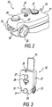
- a moveable collection device 20 comprises a tank 21 for holding drain/waste water from cooking device 1. Disposed at, preferably, one end of tank 21 and on opposing sides of tank 21 are, also preferably, one or more wheels 22 for ease of transporting moveable collection device 20 from cooking device 1 to a drain where moveable collection device 20 will be emptied.
- Moveable collection device 20 is not fixed upon a trolley or platform and includes, preferably, its own wheels for moving the moveable collection device from a position to receive drain/waste water to a position to dispose drain/waste water. Disposed on a surface of tank 21 is an opening 23 that, in Fig. 2 , is closed and sealed by use of a threaded screw cap 24.
- opening 23 could be closed by any suitable means such as a snap closure, cam actuated pressure fitted cap, and similar closures.
- opening 23 comprises a threaded portion disposed above the outer surface of moveable collection device 20, the threaded portion of which is suitable to accommodate threaded screw cap 24.
- opening 23 is disposed in relation to an opening in drain tray/catch basin according to the present disclosure, as will be explained in more detail hereinafter.
- Opening 23 is also preferably disposed near an edge surface (such as is shown in Fig. 2 ) of moveable collection device 20 so that when emptying the drain/waste water through opening 23, the emptying is complete, or nearly complete.
- Opening 23 can of course be disposed in other locations on the surface of tank 21, but other positions may not effect as complete emptying of tank 21.
- the placement of opening 23 allows for it to be both the "filling" opening for accepting drain/waste water from cooking device 1 and also the "emptying" opening for disposing of drain/waste water from tank 21.
- the structure of moveable collection device 20 does not require a separate opening for emptying on the opposite side/surface from opening 23 of water tank 21 such as is required in the above mentioned DE 10 2010 017 177 . It is believed that the opposite, separate emptying openings of the apparatus in the DE document, one for filling and one for emptying, are required because of the "fixed" position of the "water taxi” on the "trolley” disclosed therein.
- moveable collection device 20 in operation, when moveable collection device 20 is full and is removed for emptying, screw cap 24 is used to close/seal opening 23 (covered by 24 in Fig. 2 ) to prevent spillage of drain/waste water from tank 21.
- a handle 25 that, in Fig. 2 , is shown in closed, retracted position. Handle 25 is not unlike, and is similar in function to, the retractable handle commonly used for moving luggage along the ground in airports, on street sidewalks, etc.
- moveable collection device 20 may also comprise elements 26, 27 and 28.
- Element 26 is a handle that may, in some cases, be used to transport moveable collection device 20 away from cooking device 1 rather than handle 25.
- Element 27 is a "false" screw cap holder onto which screw cap 24 may be stored while moveable collection device 20 is located in a position relative to cooking device 1 and is collecting drain/waste water.
- Element 27 is an item of convenience so that screw cap 24 is less likely to be misplaced.
- Element 28 is an additional optional opening that is also secured, preferably with a cap such as screw cap 24.
- Element 28 can serve the purpose of accommodating an additional drain pipe from one or more other cooking devices 1 and/or may also be used to accept a drain/waste water level sensor device/filling indicator that may be placed into moveable collection device 20 to provide an indication when moveable collection device is full or nearly full and/or may be used to accept a source of water or other liquid to clean and rinse tank 21 of movable collection device 20. Element 28 may be omitted altogether.
- Fig. 3 is similar to Fig. 2 but shows moveable collection device 20 in an upright position for moving to and from a drain pipe, both before and after emptying, as the case may be.
- like numerals denote like elements as set forth with respect to Fig. 2 .
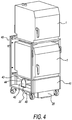
- Fig. 4 shows a configuration of moveable collection device 20 of the present disclosure in relationship to a stacked arrangement of cooking devices 1. This embodiment and relationship is for illustrative purposes only.
- two cooking devices similar in general configuration to cooking device 1 of Fig. 1 , are disposed above each other in stacked arrangement on a rack 40.
- a door 41 Disposed on the lower front side of rack 40 is a door 41 that encloses moveable collection device 20 while in operating (i.e., drain/waste water receiving) position.
- Door 41 serves to keep moveable collection device 20 in correct position with respect to its receiving drain/waste water, but also serves additional purposes, as will be explained in more detail below.
- drain tray/catch basin 42 Disposed above and toward one end of moveable collection device 20 is a drain tray/catch basin 42 that is placed in position so as to receive waste/drain waste water exiting cooking device(s) 1, in the embodiment of Fig. 4 , through one or more drain pipes (not shown in Fig. 4 ).
- drain tray/catch basin 42 is held in moveable position in relation to moveable collection device 20 and drain pipe(s) by at least one bracket 43.
- bracket 43 in the embodiment shown in Fig. 4 and the following description in relation to Figs. 5-8 , is connected to drain tray/catch basin 42 in rotatable fashion via a connector 44, such as a pin or fastener.
- bracket 43 may also be attached to rack 40 by any suitable means, such as, as shown in Fig. 4 , a retaining bracket 45.
- the means of connecting bracket 43 to drain tray/catch basin 42 is of no particular import, and can be, for example, a rivet, a screw, a pin and similar attachments.
- the attachment of retaining bracket 45 to rack 40 is of no particular import and retaining bracket 45 may be slidably attached, welded, screwed, glued, or provided with similar attachments.
- Fig 5 shows a view of moveable collection device 20 disposed below rack 40 such as shown in Fig. 4 .
- cooking devices 1 and door 41 are not shown.
- Figs. 5-6 it can be seen that in the embodiment shown, drain tray/catch basin 42 is rotatably fastened to bracket 43 by connectors 44 disposed on opposite sides of drain tray/catch basin 42 substantially equidistant from the front edge 51 of drain tray/catch basin 42 and connectors 44 are engagingly connected to each vertically disposed portion 52 of bracket 43 via a "notch" or hollow 53 designed for engaging connectors 44.
- a "notch" or hollow 53 designed for engaging connectors 44.
- connectors 44 that hold drain tray/catch basin 42 in rotatable connection to bracket 43 are shown as appendages disposed on each side of drain tray/catch basin 42.
- a drain pipe 54 (not shown in Fig.4 ), leading from cooking devices 1 (not shown in Fig. 5 ).
- Drain pipe 54 is disposed in relation to drain pipe 12 of Fig. 1 so as to receive drain/waste water therefrom. Drain/waste water from drain pipe 54 flows into drain tray/catch basin 42 and is collected and held therein.
- Drain tray/catch basin 42 Disposed in the bottom 55 of drain tray/catch basin 42, at a location preferably disposed away from the entry point of drain/waste water from drain pipe 54 into drain tray/catch basin 42, is an opening (not shown on Fig. 5 ) that is disposed above opening 23 of moveable collection device 20.
- Drain tray/catch basin 42 is preferably disposed such that drain/waste water from drain pipe 54 is inclined to run toward the opening (not shown) in bottom 55 of drain tray/catch basin 42 above opening 23 of moveable collection device 20.
- screw cap 24 has been removed from opening 23 and transferred to "false" screw cap holder 27, as noted in Fig. 5 .
- Drain/waste water drains from drain tray/catch basin 42 directly into moveable collection device 20 from opening in drain tray/catch basin 42, preferably without the use of any pipe or intervening connector between the opening in drain tray/catch basin 42 and opening 23 of moveable collection device 20.
- Fig. 6 shows one embodiment of the interaction between moveable collection device 20 and drain tray/catch basin 42 as moveable collection device 20 is removed from under drain tray/catch basin 42 and out of rack 40 for emptying.
- drain tray/catch basin 42 tilts in a manner caused by the placement of drain tray/catch basin 42 in relationship to bracket 43 and connectors 44 on drain tray/catch basin 42. Due to the arrangement of connectors 44 on drain tray/catch basin 42, drain tray/catch basin 42 is caused to tilt downwardly in the area disposed below drain pipe 54, and upwardly in the area disposed above opening 23 of moveable collection device 20.
- drain/waste water is prevented from flowing through the opening (not shown) in bottom 55 of drain tray/catch basin 42 in the area above opening 23 of moveable collection device 20.
- drain/waste water flowing from drain pipe 54 into drain tray/catch basin 42 is caused to collect and remain in drain tray/catch basin 42 in the volume of space created in drain tray/catch basin 42 between the lower edge 61 of drain tray/catch basin 42 and the opening in drain tray/catch basin 42 above opening 23 in moveable collection device 20.
- drain/waste water may continue to exit cooking device 1 via drain pipe 54 without the need for valves or other apparatus/structure to shut the flow of drain/waste water through drain pipe 54.
- drain tray/catch basin 42 may be configured, and the relationship between drain tray/catch basin 42 and bracket 43 and connectors 44 modified, so as to adjust the volume heretofore described to accommodate continued flow of drain/waste water from drain pipe 54 as necessary in any particular application (such as the distance from a floor drain into which the drain/waste water stored in moveable collection device 20 must travel before emptying).
- moveable collection device 20 is moved away from under rack 40, screw cap 24 is removed from "false” cap holder 27 and screwed onto opening 23 of moveable collection device 20 so as to close opening 23. Thereafter, moveable collection device 20 may be taken by rolling or carrying, using either handle 25 or handle 26 according to the embodiments of Figs. 2 or 3 , to a remote drain for emptying,.
- drain/waste water continues to flow into drain tray/catch basin 42 and is caused to collect and remain in drain tray/catch basin 42 in the volume of space created in tilted drain tray/catch basin 42 between lower edge 61 of drain tray/catch basin 42 and the opening (not shown) in drain tray/catch basin 42 previously disposed above opening 23 in moveable collection device 20.
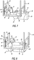
- moveable collection device 20 After moveable collection device 20 is emptied, it is returned to place in relation to drain tray/catch basin 42, and the steps described above with respect to Figs. 5 and 6 are reversed. Figs. 7 and 8 show these reversed steps.
- moveable collection device 20 In Fig. 7 moveable collection device 20 is placed back into position to resume receiving drain/waste water from drain tray/catch basin 42.
- screw cap 24 As shown in Fig. 7 , screw cap 24 is again placed on "false" screw cap holder 27 for retention.
- Fig. 8 shows moveable collection device 20 returned to position below drain tray/catch basin 42 to receive additional flow and quantity of drain/waste water from drain pipe 54.
- Figs. 9a and 9b an aspect of the interrelationship between opening 23 of moveable collection device 20 and drain tray/catch basin 42 will be described.
- opening 91 disposed on bottom 55 of drain tray/catch basin 42 is opening 91, described earlier but not shown, that is disposed above opening 23 of moveable collection device 20 while moveable collection device 20 is receiving drain/waste water flowing from drain pipe 54 into drain tray/catch basin 42.
- a protrusion 92 Surrounding a portion of the periphery of opening 91 is a protrusion 92.
- protrusion 92 may be a portion of bottom 55 of drain tray/catch basin 42, or may be an addition to bottom 55 of drain tray/catch basin 42, such as a vertically disposed flange member. Although shown as circular in Fig.
- opening 91 can be of any configuration (e.g., square, rectangular, oval, a combination of slots, and similar configurations). All that is necessary is that the inside periphery/diameter of opening 23 of moveable collection device 20 be sufficient to accommodate water flowing from the outer periphery/diameter of opening 91. In other words, the inner periphery of opening 23 regardless of its geometry should be sufficiently large to remain outside of the outer periphery of the corresponding, or opposing, geometry of opening 91. Also as shown in Figs. 9a and 9b , preferably there is disposed a flange as protrusion 92 around at least a portion of opening 91.
- protrusion 92 may be used in the following manner and perform the following functions.
- protrusion 92 assists in ensuring that drain/waste water flowing from drain pipe 54 into drain tray/catch basin 42 and therefrom into opening 23 of moveable collection device 20 is, in fact, more completely flowing into opening 23.
- protrusion 92 may aid in directing drain/waste water from drain tray/catch basin 42 into opening 23 of moveable collection device 20 to avoid or limit "splash" or spillage of drain/waste water.
- protrusion 92 may serve as a safety device in the following manner.
- protrusion 92 has an inner periphery/diameter 93 that is large enough to accommodate the raised threaded portion of opening 23 (as mentioned with respect to Fig. 2 ) when screw cap 24 is not present, but insufficient to accommodate opening 23 when screw cap 24 is present. In this manner, moveable collection device 20 cannot be accidently placed back into position for receiving drain/waste water from drain tray/catch basin 42 with opening 23 closed with screw cap 24. This has the beneficial effect of preventing drain/waste water from being spilled or disposed in any place other than into opening 23 of moveable collection device 20.
- moveable collection device 20 when protrusion 92 acts to prevent moveable collection device 20 from being fully placed into position to receive drain/waste water, moveable collection device 20 will preferably protrude from rack 40 and prevent door 41 from closing (see, Fig. 4 ).
- the present disclosure is simpler in design, construction and operation than that disclosed in the above DE10 2010 017 177 document that requires electromechanical switches and controls and fixed placement of the "water taxi” on the “trolley” to ensure that water taxi is properly placed upon return to the cooking device.
- opening 91 may be closed by a slidable seal (not shown) that is slid longitudinally into open position for allowing drain/waste water to empty from drain tray 42 as moveable collection device 20 is placed into position and slid longitudinally into closed position as moveable collection device 20 is removed for emptying.
- This sliding motion can be provided, for example, by a catch on the slidable seal that engages with the top of the moveable collection device 20 and is pushed away rearwardly as moveable collection device 20 is placed into receiving position for filling and pulled back into place as moveable collection device 20 is removed from receiving position for emptying.
- opening 91 may be closed by a seal that is rotatably slid into closed position as moveable collection device 20 is removed for emptying and rotatably slid into open position as moveable collection device 20 is placed back into position for receiving additional drain/waste water.
Landscapes
- Chemical & Material Sciences (AREA)
- Engineering & Computer Science (AREA)
- Chemical Kinetics & Catalysis (AREA)
- Combustion & Propulsion (AREA)
- Mechanical Engineering (AREA)
- General Engineering & Computer Science (AREA)
- Electrochemistry (AREA)
- Materials Engineering (AREA)
- Metallurgy (AREA)
- Organic Chemistry (AREA)
- Sink And Installation For Waste Water (AREA)
- Cookers (AREA)
Description
- The present disclosure relates to an assembly and a method for avoiding spillage of the drain/waste water. More particularly, the present disclosure relates to devices for automatically emptying the drain/waste water of cooking devices that employing moveable collection devices referred to in the state of the art as a "water taxi" and provides for minimal spillage of the drain/waste water and simplified disposal of the drain/waste water. The moveable collection devices of the present disclosure provide increased safety by reducing the possibility of a slippery floor, reducing the potential of food/food area contamination and reducing the possibility of water penetrating building construction or causing mold growth.
- Already known are moveable collection devices that can hold drain /waste water of cooking devices. These systems are sometimes called "water taxis", and are often used when the cooking devices cannot be connected or hard-piped to a floor drain system. For example, when the cooking device is installed at a distance from a drain system of the building where the cooking device is installed, the drain system of the cooking device may not be able to be connected or piped directly into that drain system. In this situation, the drain/waste water that is produced by the cooking device is fed through a pipe system of, or attached to, the cooking device, that ends in the opening of the water taxi. When the water taxi is filled it is wheeled to a nearby floor drain, where the water is disposed.
- The types of water taxi systems disclosed in the above state of the art suffer from several drawbacks. One such drawback is that when the water taxi is filled with drain/waste water the device needs to be wheeled to a floor drain for emptying. During this emptying phase, the cooking device is often still in operation causing a constant flow of drain/waste water. Drain/waste water will exit the cooking device in normal operation due to moisture from the cooking cycle in the form of condensed steam or as condensed moisture from the food being cooked. Greater quantities of water will, of course, exit the cooking device during the cleaning cycle when larger quantities of water are intentionally used to clean the inside of the cooking device. In either case, the drain/waste water will flow out of the drain pipe system of the cooking device and will fall on the kitchen floor. This situation results in safety concerns due to slippery floors, hygienic issues surrounding the presence of waste water in the environment, water possibly penetrating the building construction and forming areas of mold or other pathogens over time, etc.
- Also, according to the known state of the art devices, there is a lack of any indication of when the water taxi is full and needs emptying. Therefore, a need exists for a moveable collection device for the removal of drain/waste water that does not suffer from the drawbacks of the state of the art.
- Some of these problems are addressed in a system disclosed in
DE 10 2010 017 177 . In the disclosed system, the possibility of additional drain/waste water exiting and being spilled on the floor is somewhat alleviated. However, the disclosed system requires that the cooking device be shut off for emptying the water taxi and this is accomplished by electromechanical control of the main controller of the cooking device. Also, the system disclosed determines if the drain/waste water level is such that the water taxi needs to be emptied. However, once again, the drain/waste water level sensor is connected to the cooking device main controller and shuts off the cooking device when a filled state is reached. Thus, the disclosed system requires that the operational cycle of the cooking device be terminated (whether a cooking cycle or cleaning cycle) if the water taxi is removed or becomes full. In addition, the water taxi itself is in a complex arrangement on a sort of "trolley" or "platform" and is fixed on that trolley, has a complex filling and emptying structure, and is controlled in its operation, in part, by the placement of the trolley. For example, the disclosed water taxi has a filling port near its upper surface, and an emptying port different from the filling port disposed on its bottom surface. The filling port must be aligned with an external rigid drain pipe in order to accommodate receiving the drain/waste water. The emptying port is also complex in design, requiring communication to a separate valve that must be actuated between an open and closed position. Also included as part of the water taxi is a complex arrangement for the communication between the emptying port and the valve associated therewith, including a separate drain line. In addition, the disclosed system includes a complex drain/waste water drainage system that includes a plurality of valves that are electromechanically controlled by either the water taxi level sensor, by the water taxi trolley position, or by the door of the cabinet where the water taxi is placed. -
DE 10 2006 031 581 relates to an apparatus for heat treatment of foods, with a heated oven, which is connectable to an exhaust duct and which has a base which can be connected via a bypass line to the environment, preferably with the exhaust duct, and connected with a container for collecting fat and grease from the floor drain. The floor drain opens out into a branch with a first and a second output, where the first output via a valve is connectable to a sewer, and to the second output via a valve. The second output is at a higher level than the first output and the bottom of the branch to the first output has a slope which is between 0° and 30°. A cleaning device is provided for cleaning the cooking chamber, and wherein the branch is designed such that residues and cleaning agent can flow out. -
EP 2 389 808 relates to device for heat treatment of food products consisting of a heat treatment apparatus and a base cupboard. The heat treatment device may be an oven or a combi steamer. The device has a vaporization or a cleaning system for the heat treatment apparatus. Usually both units are present, whereby the amount of resulting liquids is particularly high. In the heat treatment apparatus condensate and/or accumulating cleaning fluid is passed through several pipelines in the cabinet, where there is a waste water tank for receiving the condensate and/or the cleaning liquid. The waste water tank is integrated into a mobile tank device which consists of a movable floor beam on which the waste water tank is attached. The movable base carrier has wheels, which should be at least partially steerable. The waste water tank has at least one filling opening and a discharge opening. The filling opening can be used as a vent port simultaneously. Usually, however, an extra vent will be present. The discharge opening is connected to a manually operable outlet valve. -
EP 0 425 474 relates to a portable gas grill having a cart of generally rectangular configuration and consisting of a plurality of tubular members and including at least two transversely-spaced upper members defining a space therebetween. A housing defining a cooking chamber and having opposed ledges supported on the upper members. The housing has a cooking grid adjacent an upper edge and a cover thereon, and a removable side burner that is supported on the upper members adjacent the housing. The portable grill has a V-shaped bottom tray for receiving cooking waste and is configured to trap heat from the portable grill to vaporize the cooking waste. - It is, therefore, an object of the present disclosure to provide a moveable collection device for the removal of drain/waste water from a cooking device that prevents the continual draining of drain/waste water onto the floor while the moveable collection device is out of place and being emptied, even if the operation of the cooking device is not stopped.
- It is also an object of the present disclosure to provide a moveable collection device for the removal of drain/waste water from a cooking device in which the moveable collection device provides an indication that it is ready to be emptied by a drain/waste water level sensor, but where the sensor, preferably, does not control the operation cycle of the cooking device.
- The above and other objects are met by the assembly according to
claim 1 and a method according toclaim 8. The cooking device itself is of general, known design. - One embodiment of the present disclosure relates to an assembly comprising a cooking device, in particular a commercial cooking device (such as, preferably, a combisteamer, a baking oven or a microwave oven) comprising a housing including a cooking chamber, a door for opening and closing the cooking chamber, and a drain for allowing drain/waste water to drain from the cooking device. External to the cooking device and in close association with the drain is a drain tray or catch basin that is disposed in cooperative relationship with a moveable collection device for the removal of drain/waste water from the drain tray/catch basin. The flow of drain/waste water into the drain and thereafter into the drain tray/catch basin is, preferably, not controlled by a valve or stop of any sort, and the drain/waste water may continually drain from the cooking device into the drain tray/catch basin even when the moveable collection device is removed. The moveable collection device is disposed in relation to the drain tray/catch basin so that when the moveable collection device is removed for emptying, the drain tray/catch basin is rotated to continue to receive drain/waste water exiting the cooking chamber through the drain, but is configured so that drain/waste water that enters the drain tray/catch basin remains therein until the moveable collection device is returned to position underneath the drain tray/catch basin. This ability of the drain tray/catch basin to continue to receive drain/waste water exiting the cooking device is, preferably, attained without the use of any valve or stop of any sort.
- In another embodiment of the present disclosure, a method of receiving and disposing of drain/waste water produced during operation of the cooking device by the device to hold the drain/waste water, performed by the assembly according to the invention, is provided. The method is performed as follows: disposing the moveable collection device in relation to the drain tray/catch basin, collecting drain/waste water from the drain that passes into the drain tray/catch basin, passing the drain/waste water from the drain tray/catch basin to the moveable collection device, removing the moveable collection device for emptying, wherein the drain tray/catch basin is rotated to continue to receive drain/waste water exiting the cooking chamber through the drain, and preventing drain/waste water that enters the drain tray/catch basin while the moveable collection device is removed from exiting the drain tray/catch basin.
- Further features, advantages and details of the present disclosure will become apparent from the following description of the drawings in that:
-
Fig. 1 shows a schematically simplified side cross-sectional view of a cooking device according to the present disclosure; -
Fig. 2 is a top front perspective view of a moveable collection device according to the present disclosure; -
Fig. 3 is a perspective view of a moveable collection device according to the present disclosure in upright position for rolling to a drain for emptying; -
Fig. 4 shows a schematic view of two cooking devices in stacked configuration with a moveable collection device according to the present disclosure disposed thereunder behind a door; -
Figs. 5-6 show an embodiment of the method of present disclosure wherein the moveable collection device is being removed, with the drain tray thereafter disposed in position to continue to catch drain/waste water from the cooking devices; -
Figs. 7-8 show the same embodiment as shown inFigs. 5-6 wherein the moveable collection device is being placed back into position to receive drain/waste water from the drain tray; and -
Figs. 9a and 9b show views of the underside of the drain tray/catch basin according to one embodiment of the present disclosure. -
Fig. 1 shows thecooking device 1 as a generalized combisteamer suitable for use in accordance with the present disclosure.Cooking device 1 inFig. 1 has a housing 2 containing a cooking chamber 3 and a heating chamber 4 divided by a suction panel 5 that separates cooking chamber 3 from heating chamber 4 and thereby protects a fan wheel 6 and a heating element/coil 7 from being damaged or touched. - Through a central area of suction panel 5 is a
suction panel opening 8, through which air is sucked from cooking chamber 3 to heating chamber 4 in the direction of arrows "A" and distributed and heated with fan wheel 6 and heating element/coil 7. During steam cooking, water is distributed within heating chamber 4 through an inlet pipe (not shown) disposed in heating chamber 4. For dehumidification during cooking, aflap 9 is opened and fresh air is sucked into the chamber in the direction of arrow "B" via anintake suction pipe 10. Fresh cold air is sucked into cooking chamber 3 viaintake pipe 10 and the cold air flowing throughintake pipe 10 is pushed into cooking chamber 3 by fan wheel 6 in the direction of arrows "C", causing wet air in cooking chamber 3 to be pushed out through adrain 13 as condensed heated air from cooking chamber 3 into acondenser tray 14. Thereafter, the condensed heated air collected as liquid incondenser tray 14 drains into and through adrain pipe 12. Heated air exits into the environment through anair outlet pipe 15. Awater inlet pipe 11 is often employed for fillingcondenser tray 14 for various purposes, such as during the cleaning cycle of cooking chamber 3 ofcooking device 1. At the time of cleaning,drain pipe 12 will be closed (by a mechanism not shown) so that the cleaning cycle can be completed without the loss of cleaning liquid, etc., throughdrain pipe 12. - As can be appreciated, and as is known to those skilled in the art, drain/waste water exits
cooking device 1 under varied circumstances, for example, during steaming for steam cooking, during dehumidification and, generally, after cleaning as noted above (although when progressing from, for example, a cleaning cycle to a rinsing cycle, drain/waste water may exitcooking device 1 between cycles), but also under normal cooking operation due to moisture from the food being cooked that is driven off and exits cooking chamber 3. Thus, it is not uncommon for drain/waste water to be continually draining fromcooking device 1. - In
Fig. 2 , amoveable collection device 20 comprises atank 21 for holding drain/waste water fromcooking device 1. Disposed at, preferably, one end oftank 21 and on opposing sides oftank 21 are, also preferably, one ormore wheels 22 for ease of transportingmoveable collection device 20 fromcooking device 1 to a drain wheremoveable collection device 20 will be emptied.Moveable collection device 20 is not fixed upon a trolley or platform and includes, preferably, its own wheels for moving the moveable collection device from a position to receive drain/waste water to a position to dispose drain/waste water. Disposed on a surface oftank 21 is anopening 23 that, inFig. 2 , is closed and sealed by use of a threadedscrew cap 24. Of course, opening 23 could be closed by any suitable means such as a snap closure, cam actuated pressure fitted cap, and similar closures. In the embodiment shown inFIG. 2 , opening 23 comprises a threaded portion disposed above the outer surface ofmoveable collection device 20, the threaded portion of which is suitable to accommodate threadedscrew cap 24. In use, opening 23 is disposed in relation to an opening in drain tray/catch basin according to the present disclosure, as will be explained in more detail hereinafter.Opening 23 is also preferably disposed near an edge surface (such as is shown inFig. 2 ) ofmoveable collection device 20 so that when emptying the drain/waste water throughopening 23, the emptying is complete, or nearly complete.Opening 23 can of course be disposed in other locations on the surface oftank 21, but other positions may not effect as complete emptying oftank 21. The placement of opening 23 allows for it to be both the "filling" opening for accepting drain/waste water fromcooking device 1 and also the "emptying" opening for disposing of drain/waste water fromtank 21. In this manner, the structure ofmoveable collection device 20 does not require a separate opening for emptying on the opposite side/surface from opening 23 ofwater tank 21 such as is required in the above mentionedDE 10 2010 017 177 - According to the present disclosure, in operation, when
moveable collection device 20 is full and is removed for emptying,screw cap 24 is used to close/seal opening 23 (covered by 24 inFig. 2 ) to prevent spillage of drain/waste water fromtank 21. Also as part of the embodiment ofmoveable collection device 20 is ahandle 25 that, inFig. 2 , is shown in closed, retracted position.Handle 25 is not unlike, and is similar in function to, the retractable handle commonly used for moving luggage along the ground in airports, on street sidewalks, etc. InFig. 2 ,moveable collection device 20 may also compriseelements Element 26 is a handle that may, in some cases, be used to transportmoveable collection device 20 away from cookingdevice 1 rather than handle 25.Element 27 is a "false" screw cap holder onto whichscrew cap 24 may be stored whilemoveable collection device 20 is located in a position relative tocooking device 1 and is collecting drain/waste water.Element 27 is an item of convenience so thatscrew cap 24 is less likely to be misplaced.Element 28 is an additional optional opening that is also secured, preferably with a cap such asscrew cap 24.Element 28 can serve the purpose of accommodating an additional drain pipe from one or moreother cooking devices 1 and/or may also be used to accept a drain/waste water level sensor device/filling indicator that may be placed intomoveable collection device 20 to provide an indication when moveable collection device is full or nearly full and/or may be used to accept a source of water or other liquid to clean and rinsetank 21 ofmovable collection device 20.Element 28 may be omitted altogether. -
Fig. 3 is similar toFig. 2 but showsmoveable collection device 20 in an upright position for moving to and from a drain pipe, both before and after emptying, as the case may be. InFig. 3 , like numerals denote like elements as set forth with respect toFig. 2 . -
Fig. 4 shows a configuration ofmoveable collection device 20 of the present disclosure in relationship to a stacked arrangement ofcooking devices 1. This embodiment and relationship is for illustrative purposes only. InFig. 4 , it can be seen that twocooking devices 1, similar in general configuration tocooking device 1 ofFig. 1 , are disposed above each other in stacked arrangement on arack 40. Disposed on the lower front side ofrack 40 is adoor 41 that enclosesmoveable collection device 20 while in operating (i.e., drain/waste water receiving) position.Door 41 serves to keepmoveable collection device 20 in correct position with respect to its receiving drain/waste water, but also serves additional purposes, as will be explained in more detail below. Disposed above and toward one end ofmoveable collection device 20 is a drain tray/catch basin 42 that is placed in position so as to receive waste/drain waste water exiting cooking device(s) 1, in the embodiment ofFig. 4 , through one or more drain pipes (not shown inFig. 4 ). As will also be explained in more detail below with respect to the embodiments inFigs. 4-8 , drain tray/catch basin 42 is held in moveable position in relation tomoveable collection device 20 and drain pipe(s) by at least onebracket 43. In turn,bracket 43, in the embodiment shown inFig. 4 and the following description in relation toFigs. 5-8 , is connected to drain tray/catch basin 42 in rotatable fashion via aconnector 44, such as a pin or fastener. For support,bracket 43 may also be attached to rack 40 by any suitable means, such as, as shown inFig. 4 , a retainingbracket 45. The means of connectingbracket 43 to drain tray/catch basin 42 is of no particular import, and can be, for example, a rivet, a screw, a pin and similar attachments. In the same manner, the attachment of retainingbracket 45 to rack 40 is of no particular import and retainingbracket 45 may be slidably attached, welded, screwed, glued, or provided with similar attachments. -
Fig 5 . shows a view ofmoveable collection device 20 disposed belowrack 40 such as shown inFig. 4 . InFig. 5 ,cooking devices 1 anddoor 41 are not shown. InFigs. 5-6 , it can be seen that in the embodiment shown, drain tray/catch basin 42 is rotatably fastened tobracket 43 byconnectors 44 disposed on opposite sides of drain tray/catch basin 42 substantially equidistant from thefront edge 51 of drain tray/catch basin 42 andconnectors 44 are engagingly connected to each vertically disposedportion 52 ofbracket 43 via a "notch" or hollow 53 designed for engagingconnectors 44. In the embodiment shown inFigs. 5-8 ,connectors 44 that hold drain tray/catch basin 42 in rotatable connection tobracket 43 are shown as appendages disposed on each side of drain tray/catch basin 42. As can be seen inFig. 5 , disposed above and toward one edge of drain tray/catch basin 42 is a drain pipe 54 (not shown inFig.4 ), leading from cooking devices 1 (not shown inFig. 5 ).Drain pipe 54 is disposed in relation to drainpipe 12 ofFig. 1 so as to receive drain/waste water therefrom. Drain/waste water fromdrain pipe 54 flows into drain tray/catch basin 42 and is collected and held therein. Disposed in the bottom 55 of drain tray/catch basin 42, at a location preferably disposed away from the entry point of drain/waste water fromdrain pipe 54 into drain tray/catch basin 42, is an opening (not shown onFig. 5 ) that is disposed above opening 23 ofmoveable collection device 20. Drain tray/catch basin 42 is preferably disposed such that drain/waste water fromdrain pipe 54 is inclined to run toward the opening (not shown) inbottom 55 of drain tray/catch basin 42 above opening 23 ofmoveable collection device 20. In the embodiment shown inFig. 5 ,screw cap 24 has been removed from opening 23 and transferred to "false"screw cap holder 27, as noted inFig. 5 . Drain/waste water drains from drain tray/catch basin 42 directly intomoveable collection device 20 from opening in drain tray/catch basin 42, preferably without the use of any pipe or intervening connector between the opening in drain tray/catch basin 42 andopening 23 ofmoveable collection device 20. -
Fig. 6 shows one embodiment of the interaction betweenmoveable collection device 20 and drain tray/catch basin 42 asmoveable collection device 20 is removed from under drain tray/catch basin 42 and out ofrack 40 for emptying. InFig. 6 , asmoveable collection device 20 is removed from beneath drain tray/catch basin 42, drain tray/catch basin 42 tilts in a manner caused by the placement of drain tray/catch basin 42 in relationship tobracket 43 andconnectors 44 on drain tray/catch basin 42. Due to the arrangement ofconnectors 44 on drain tray/catch basin 42, drain tray/catch basin 42 is caused to tilt downwardly in the area disposed belowdrain pipe 54, and upwardly in the area disposed above opening 23 ofmoveable collection device 20. As this movement is effected, drain/waste water is prevented from flowing through the opening (not shown) inbottom 55 of drain tray/catch basin 42 in the area above opening 23 ofmoveable collection device 20. At the same time, drain/waste water flowing fromdrain pipe 54 into drain tray/catch basin 42 is caused to collect and remain in drain tray/catch basin 42 in the volume of space created in drain tray/catch basin 42 between thelower edge 61 of drain tray/catch basin 42 and the opening in drain tray/catch basin 42 above opening 23 inmoveable collection device 20. Thus,cooking device 1 need not be stopped in its operation or its cooking or cleaning cycle shut off whenmoveable collection device 20 is removed for emptying, and drain/waste water may continue to exitcooking device 1 viadrain pipe 54 without the need for valves or other apparatus/structure to shut the flow of drain/waste water throughdrain pipe 54. Of course, drain tray/catch basin 42 may be configured, and the relationship between drain tray/catch basin 42 andbracket 43 andconnectors 44 modified, so as to adjust the volume heretofore described to accommodate continued flow of drain/waste water fromdrain pipe 54 as necessary in any particular application (such as the distance from a floor drain into which the drain/waste water stored inmoveable collection device 20 must travel before emptying). - Subsequent to the position of
moveable collection device 20 depicted inFig. 6 ,moveable collection device 20 is moved away from underrack 40,screw cap 24 is removed from "false"cap holder 27 and screwed onto opening 23 ofmoveable collection device 20 so as to closeopening 23. Thereafter,moveable collection device 20 may be taken by rolling or carrying, using either handle 25 or handle 26 according to the embodiments ofFigs. 2 or 3 , to a remote drain for emptying,. As mentioned above, whilemoveable collection device 20 is not receiving drain/waste water fromdrain pipe 54, the drain/waste water continues to flow into drain tray/catch basin 42 and is caused to collect and remain in drain tray/catch basin 42 in the volume of space created in tilted drain tray/catch basin 42 betweenlower edge 61 of drain tray/catch basin 42 and the opening (not shown) in drain tray/catch basin 42 previously disposed above opening 23 inmoveable collection device 20. - After
moveable collection device 20 is emptied, it is returned to place in relation to drain tray/catch basin 42, and the steps described above with respect toFigs. 5 and 6 are reversed.Figs. 7 and 8 show these reversed steps. InFig. 7 moveable collection device 20 is placed back into position to resume receiving drain/waste water from drain tray/catch basin 42. As shown inFig. 7 ,screw cap 24 is again placed on "false"screw cap holder 27 for retention.Fig. 8 showsmoveable collection device 20 returned to position below drain tray/catch basin 42 to receive additional flow and quantity of drain/waste water fromdrain pipe 54. Now, in connection withFigs. 9a and 9b , an aspect of the interrelationship between opening 23 ofmoveable collection device 20 and drain tray/catch basin 42 will be described. - As shown in
Fig. 9a , disposed onbottom 55 of drain tray/catch basin 42 is opening 91, described earlier but not shown, that is disposed above opening 23 ofmoveable collection device 20 whilemoveable collection device 20 is receiving drain/waste water flowing fromdrain pipe 54 into drain tray/catch basin 42. Surrounding a portion of the periphery of opening 91 is aprotrusion 92. As shown infig. 9b ,protrusion 92 may be a portion ofbottom 55 of drain tray/catch basin 42, or may be an addition to bottom 55 of drain tray/catch basin 42, such as a vertically disposed flange member. Although shown as circular inFig. 9a , opening 91 can be of any configuration (e.g., square, rectangular, oval, a combination of slots, and similar configurations). All that is necessary is that the inside periphery/diameter of opening 23 ofmoveable collection device 20 be sufficient to accommodate water flowing from the outer periphery/diameter ofopening 91. In other words, the inner periphery of opening 23 regardless of its geometry should be sufficiently large to remain outside of the outer periphery of the corresponding, or opposing, geometry ofopening 91. Also as shown inFigs. 9a and 9b , preferably there is disposed a flange asprotrusion 92 around at least a portion ofopening 91. When employed,protrusion 92 may be used in the following manner and perform the following functions. In part,protrusion 92 assists in ensuring that drain/waste water flowing fromdrain pipe 54 into drain tray/catch basin 42 and therefrom into opening 23 ofmoveable collection device 20 is, in fact, more completely flowing intoopening 23. In this respect,protrusion 92 may aid in directing drain/waste water from drain tray/catch basin 42 into opening 23 ofmoveable collection device 20 to avoid or limit "splash" or spillage of drain/waste water. In another aspect,protrusion 92 may serve as a safety device in the following manner. In a preferred embodiment,protrusion 92 has an inner periphery/diameter 93 that is large enough to accommodate the raised threaded portion of opening 23 (as mentioned with respect toFig. 2 ) whenscrew cap 24 is not present, but insufficient to accommodateopening 23 whenscrew cap 24 is present. In this manner,moveable collection device 20 cannot be accidently placed back into position for receiving drain/waste water from drain tray/catch basin 42 with opening 23 closed withscrew cap 24. This has the beneficial effect of preventing drain/waste water from being spilled or disposed in any place other than into opening 23 ofmoveable collection device 20. Also, whenprotrusion 92 acts to preventmoveable collection device 20 from being fully placed into position to receive drain/waste water,moveable collection device 20 will preferably protrude fromrack 40 and preventdoor 41 from closing (see,Fig. 4 ). In this respect, the present disclosure is simpler in design, construction and operation than that disclosed in the aboveDE10 2010 017 177 document that requires electromechanical switches and controls and fixed placement of the "water taxi" on the "trolley" to ensure that water taxi is properly placed upon return to the cooking device. - Other embodiments of constructing/designing
opening 91 so that water does not empty whilemoveable collection device 20 is moved away for emptying or other reason are envisioned. For example, opening 91 may be closed by a slidable seal (not shown) that is slid longitudinally into open position for allowing drain/waste water to empty fromdrain tray 42 asmoveable collection device 20 is placed into position and slid longitudinally into closed position asmoveable collection device 20 is removed for emptying. This sliding motion can be provided, for example, by a catch on the slidable seal that engages with the top of themoveable collection device 20 and is pushed away rearwardly asmoveable collection device 20 is placed into receiving position for filling and pulled back into place asmoveable collection device 20 is removed from receiving position for emptying. In an alternative sliding arrangement, opening 91 may be closed by a seal that is rotatably slid into closed position asmoveable collection device 20 is removed for emptying and rotatably slid into open position asmoveable collection device 20 is placed back into position for receiving additional drain/waste water.
Claims (14)
- An assembly comprising a cooking device (1) and a device to hold the drain/waste water from the cooking device,
wherein the cooking device (1) comprises a housing (2) including a cooking chamber (3) and a drain (13) for allowing drain/waste water to drain from the cooking device (1), the cooking device (1) being in cooperative relation with the device to hold the drain/waste water,
wherein the device to hold the drain/waste water comprises:a drain tray (42) external to the cooking device (1) for receiving the drain/ waste water from a drain pipe (54), the drain tray (42) comprising:i) a bottom (55) and sides to form a volume,ii) an opening (91) disposed in the bottom (55) for allowing the drain/waste water to exit the drain tray (42) and,a movable collection device (20), wherein the movable collection device (20) is movable between a position for receiving the drain/waste water from the opening (91) of the drain tray (42), and a position for disposing the drain/ waste water, the movable collection device (20) including an opening (23) for receiving the drain/waste water from the drain tray (42) opening (91),a rack (40) on which the cooking device is disposed,wherein the rack (40) comprises a door (41) disposed on its lower front side that encloses the movable collection (20) device in the position for receiving the drain/waste water and that serves to keep the movable collection device (20) in correct position when it receives drain/waste water,
characterized in that
the drain tray (42) further comprises connectors (44) disposed on opposite sides of the drain tray (42) substantially equidistant from a front edge (51) of the drain tray (42),
wherein each connector (44) is engagingly connected to a vertically disposed portion of a bracket (43) via a notch (53) designed for engaging the connectors (44),
wherein the bracket (43) is attached to the rack (40), and
wherein when the movable collection device (20) is moved to the position for disposing the drain/waste water, the drain tray (42) rotates about the connectors (44) engaged in the brackets (43) so that the drain tray (42) continues to receive additional drain/waste water exiting the cooking chamber (3) through the drain and prevents said additional water from exiting the drain tray (42). - The device according to claim 1, wherein the connectors (44) of the drain tray (42) are engagingly connected to each vertically disposed portion (52) of bracket (43) via the notch (53) such that the rotation of the drain tray (42) causes a lower edge (61) of the drain tray (42) to lower away from the drain pipe (54) and causes the opening (91) of the drain tray (42) to elevate.
- The device according to claim 2, wherein the rotation of the drain tray (42) creates a volume in the drain tray (42) between the lower edge (61) of the drain tray (42) and the opening (91) in the drain tray (42), wherein the volume is disposed away from the opening (91) in the drain tray (42) to receive additional drain/waste water from the drain pipe (54).
- The device according to claim 1, wherein the opening (23) of the moveable collection device (20) for receiving the drain/waste water is also used for emptying the drain/waste water from the moveable collection device (20).
- The device according to claim 1, wherein the opening (23) of the moveable collection device (20) for receiving the drain/waste water has associated therewith a closure.
- The device according to claim 5, wherein the closure is a threaded screw cap (24) configured to engage a threaded portion of the opening (23) disposed above the outer surface of moveable collection device (20).
- The device according to claim 5, wherein the drain tray (42) further comprises a protrusion (92) disposed on the bottom (55) surrounding a portion of the opening (91) that prevents the moveable collection device (20) from being placed into position for receiving drain/waste water from the drain pipe (54) if the closure (24) is associated with the threaded portion.
- A method of receiving and disposing of drain/waste water produced during operation of a cooking device (1) by the device to hold the drain/waste water performed by an assembly according to any of claims 1-7,
the method characterized by:allowing the drain/waste water exiting the drain (13) from the cooking device (1) to be received through the drain pipe (54) by the drain tray (42);allowing the drain/waste water in the drain tray (42) to exit the drain tray (42) by the opening (91);allowing the drain/waste water that exits the drain tray (42) by the opening (91) to be received by the moveable collection device (20) through the opening (23) in the moveable collection device (20); andremoving the moveable collection device (20) to dispose of the drain/waste water, wherein the drain tray (42) rotates and continues to receive additional drain/waste water exiting the cooking chamber (3) through the drain (13) and prevents said additional water from exiting the drain tray (42). - The method according to claim 8, wherein the rotation of the drain tray (42) causes the lower edge (61) of the drain tray (42) to lower away from the drain pipe (54) and causes the opening (91) of the drain tray (42) to elevate.
- The method according to claim 9, wherein the rotation of the drain tray (42) creates a volume in the drain tray (42) between the lower edge (61) of the drain tray (42) and the opening (91) in the drain tray (42), wherein the volume is disposed away from the opening (91) in the drain tray (42) and receives additional drain/waste water from the drain pipe (54).
- The method according to claim 9, wherein the emptying of the drain/waste water from the moveable collection (20) device uses the opening (23) of the moveable collection device (20) that is used for receiving the drain/waste water.
- The method according to claim 9, wherein the opening (23) of the moveable collection device (20) for receiving the drain/waste water has associated therewith a closure.
- The method according to claim 12, wherein the closure is a threaded screw cap (24) configured to engage a threaded portion of the opening (23) disposed above the outer surface of the moveable collection device (20).
- The method according to claim 13, wherein the drain tray (42) further comprises a protrusion (92) on the bottom (55) surrounding a portion of opening (91) that prevents the moveable collection device (20) from being placed into position for receiving drain/waste water from the opening (91) if the threaded screw cap (24) is associated with the threaded portion.
Applications Claiming Priority (2)
| Application Number | Priority Date | Filing Date | Title |
|---|---|---|---|
| US201261662653P | 2012-06-21 | 2012-06-21 | |
| PCT/IB2013/001303 WO2013190368A1 (en) | 2012-06-21 | 2013-06-20 | Drain water collection with automatic emptying and spillage reduction functionality for cooking devices |
Publications (2)
| Publication Number | Publication Date |
|---|---|
| EP2864708A1 EP2864708A1 (en) | 2015-04-29 |
| EP2864708B1 true EP2864708B1 (en) | 2019-06-19 |
Family
ID=48918447
Family Applications (1)
| Application Number | Title | Priority Date | Filing Date |
|---|---|---|---|
| EP13745714.9A Not-in-force EP2864708B1 (en) | 2012-06-21 | 2013-06-20 | Cooking device with drain water collection with spillage reduction functionality |
Country Status (3)
| Country | Link |
|---|---|
| EP (1) | EP2864708B1 (en) |
| CN (1) | CN104620053B (en) |
| WO (1) | WO2013190368A1 (en) |
Families Citing this family (2)
| Publication number | Priority date | Publication date | Assignee | Title |
|---|---|---|---|---|
| JP2022547950A (en) | 2019-09-10 | 2022-11-16 | ラム リサーチ コーポレーション | In-situ sensor fusion using artificial intelligence |
| IT202000017674A1 (en) | 2020-07-21 | 2022-01-21 | Angelo Po Grandi Cucine Spa | APPARATUS FOR COOKING FOOD AND RELATED METHOD OF MANAGEMENT |
Family Cites Families (10)
| Publication number | Priority date | Publication date | Assignee | Title |
|---|---|---|---|---|
| US3964378A (en) * | 1974-03-22 | 1976-06-22 | The Frymaster Corporation | Tilting frypan with drain system |
| EP0425474A1 (en) * | 1985-07-26 | 1991-05-02 | Weber-Stephen Products Co. | Portable gas grill |
| US6247468B1 (en) * | 1999-08-30 | 2001-06-19 | Kenneth L. Wood | Fluid collector for barbecue grill |
| WO2004094912A1 (en) * | 2003-04-22 | 2004-11-04 | Alto-Shaam, Inc. | Oven with grease collection system |
| CN2666322Y (en) * | 2003-12-31 | 2004-12-29 | 陈志鹏 | Device for discharging condensed water from steaming cabinet |
| DE102006031581B4 (en) * | 2006-07-03 | 2010-09-23 | Wiesheu Gmbh | Device for heat treatment of foods with fat separation |
| IT1394578B1 (en) * | 2009-05-06 | 2012-07-05 | Angelo Grandi Cucine Societa Per Azioni | METHOD AND APPARATUS FOR THE COLLECTION OF FATS DERIVING FROM THE COOKING OF FOOD |
| DE102010017177A1 (en) | 2010-05-31 | 2011-12-01 | Debag Deutsche Backofenbau Gmbh | Heat treatment device for e.g. baking of food products at bakery, has waste water tank fastened at movable floor support and possessing filling hole and emptying hole that is attached at actuated outlet valve |
| DE202010005532U1 (en) * | 2010-05-31 | 2010-09-16 | Debag Deutsche Backofenbau Gmbh | Device for heat treatment of food |
| DE102013110974A1 (en) * | 2013-03-19 | 2014-09-25 | Hanning Elektro-Werke Gmbh & Co. Kg | Cleaning device for kitchen appliances and pump system |
-
2013
- 2013-06-20 WO PCT/IB2013/001303 patent/WO2013190368A1/en not_active Ceased
- 2013-06-20 EP EP13745714.9A patent/EP2864708B1/en not_active Not-in-force
- 2013-06-20 CN CN201380040737.XA patent/CN104620053B/en not_active Expired - Fee Related
Non-Patent Citations (1)
| Title |
|---|
| None * |
Also Published As
| Publication number | Publication date |
|---|---|
| WO2013190368A8 (en) | 2015-01-08 |
| EP2864708A1 (en) | 2015-04-29 |
| CN104620053A (en) | 2015-05-13 |
| CN104620053B (en) | 2017-04-19 |
| WO2013190368A1 (en) | 2013-12-27 |
Similar Documents
| Publication | Publication Date | Title |
|---|---|---|
| CA2877450A1 (en) | Drain water collection with automatic emptying and spillage reduction functionality for cooking devices | |
| KR101315619B1 (en) | Dishwasher and a water tank adapted for a dishwasher | |
| US7421942B2 (en) | Grease collection system for oven | |
| CN103126544B (en) | A kind of baking box and the method for operation of oven | |
| CA2794160C (en) | Method for storing used cooking oil | |
| US9968220B2 (en) | Drain water collection with automatic emptying and spillage reduction functionality for cooking devices | |
| US10001283B2 (en) | Cooking device with fat drain | |
| US5908551A (en) | Grease caddie | |
| US20200408441A1 (en) | Table fan and method for cleaning a table fan | |
| WO2013190368A1 (en) | Drain water collection with automatic emptying and spillage reduction functionality for cooking devices | |
| US10087066B1 (en) | Liquid collection device that catches and transports, without spills, drain water from a piece of equipment, such as an ice table, and a system including the table and collection device | |
| DE102010017177A1 (en) | Heat treatment device for e.g. baking of food products at bakery, has waste water tank fastened at movable floor support and possessing filling hole and emptying hole that is attached at actuated outlet valve | |
| EP2389808A1 (en) | Device for heat treatement of foods | |
| EP3128884B1 (en) | Drainage device for a cooking appliance | |
| US3021777A (en) | Grease extracting vent with heating means | |
| CN208211934U (en) | A kind of novel Fryer | |
| US9776115B1 (en) | Mobile device for recovery and on site storage of used cooking oil | |
| ES2349133T3 (en) | MACHINE FOR THE PREPARATION OF MEALS. | |
| JP2017081691A (en) | Waste container | |
| EP4379265A1 (en) | Container for collection of flowing substances, drainage auxiliary tool and household appliance | |
| CN215077497U (en) | Energy-saving cart type steaming cabinet capable of being automatically cleaned | |
| KR20190129632A (en) | Cooking apparatus | |
| US20230301474A1 (en) | Wet/dry vacuum stand and bottom discharge | |
| US20250334275A1 (en) | Appliance for cooking dishes | |
| WO2023007264A1 (en) | Automated table for catering |
Legal Events
| Date | Code | Title | Description |
|---|---|---|---|
| PUAI | Public reference made under article 153(3) epc to a published international application that has entered the european phase |
Free format text: ORIGINAL CODE: 0009012 |
|
| 17P | Request for examination filed |
Effective date: 20141205 |
|
| AK | Designated contracting states |
Kind code of ref document: A1 Designated state(s): AL AT BE BG CH CY CZ DE DK EE ES FI FR GB GR HR HU IE IS IT LI LT LU LV MC MK MT NL NO PL PT RO RS SE SI SK SM TR |
|
| AX | Request for extension of the european patent |
Extension state: BA ME |
|
| DAX | Request for extension of the european patent (deleted) | ||
| 17Q | First examination report despatched |
Effective date: 20160519 |
|
| STAA | Information on the status of an ep patent application or granted ep patent |
Free format text: STATUS: EXAMINATION IS IN PROGRESS |
|
| REG | Reference to a national code |
Ref country code: DE Ref legal event code: R079 Ref document number: 602013056797 Country of ref document: DE Free format text: PREVIOUS MAIN CLASS: F24C0014000000 Ipc: F24C0015320000 |
|
| GRAP | Despatch of communication of intention to grant a patent |
Free format text: ORIGINAL CODE: EPIDOSNIGR1 |
|
| STAA | Information on the status of an ep patent application or granted ep patent |
Free format text: STATUS: GRANT OF PATENT IS INTENDED |
|
| RIC1 | Information provided on ipc code assigned before grant |
Ipc: F24C 15/32 20060101AFI20181210BHEP Ipc: F24C 14/00 20060101ALI20181210BHEP |
|
| INTG | Intention to grant announced |
Effective date: 20190104 |
|
| GRAS | Grant fee paid |
Free format text: ORIGINAL CODE: EPIDOSNIGR3 |
|
| GRAA | (expected) grant |
Free format text: ORIGINAL CODE: 0009210 |
|
| STAA | Information on the status of an ep patent application or granted ep patent |
Free format text: STATUS: THE PATENT HAS BEEN GRANTED |
|
| AK | Designated contracting states |
Kind code of ref document: B1 Designated state(s): AL AT BE BG CH CY CZ DE DK EE ES FI FR GB GR HR HU IE IS IT LI LT LU LV MC MK MT NL NO PL PT RO RS SE SI SK SM TR |
|
| REG | Reference to a national code |
Ref country code: GB Ref legal event code: FG4D |
|
| REG | Reference to a national code |
Ref country code: CH Ref legal event code: EP |
|
| REG | Reference to a national code |
Ref country code: IE Ref legal event code: FG4D |
|
| REG | Reference to a national code |
Ref country code: DE Ref legal event code: R096 Ref document number: 602013056797 Country of ref document: DE |
|
| REG | Reference to a national code |
Ref country code: AT Ref legal event code: REF Ref document number: 1146021 Country of ref document: AT Kind code of ref document: T Effective date: 20190715 |
|
| REG | Reference to a national code |
Ref country code: NL Ref legal event code: MP Effective date: 20190619 |
|
| PG25 | Lapsed in a contracting state [announced via postgrant information from national office to epo] |
Ref country code: NO Free format text: LAPSE BECAUSE OF FAILURE TO SUBMIT A TRANSLATION OF THE DESCRIPTION OR TO PAY THE FEE WITHIN THE PRESCRIBED TIME-LIMIT Effective date: 20190919 Ref country code: LT Free format text: LAPSE BECAUSE OF FAILURE TO SUBMIT A TRANSLATION OF THE DESCRIPTION OR TO PAY THE FEE WITHIN THE PRESCRIBED TIME-LIMIT Effective date: 20190619 Ref country code: FI Free format text: LAPSE BECAUSE OF FAILURE TO SUBMIT A TRANSLATION OF THE DESCRIPTION OR TO PAY THE FEE WITHIN THE PRESCRIBED TIME-LIMIT Effective date: 20190619 Ref country code: AL Free format text: LAPSE BECAUSE OF FAILURE TO SUBMIT A TRANSLATION OF THE DESCRIPTION OR TO PAY THE FEE WITHIN THE PRESCRIBED TIME-LIMIT Effective date: 20190619 Ref country code: SE Free format text: LAPSE BECAUSE OF FAILURE TO SUBMIT A TRANSLATION OF THE DESCRIPTION OR TO PAY THE FEE WITHIN THE PRESCRIBED TIME-LIMIT Effective date: 20190619 Ref country code: HR Free format text: LAPSE BECAUSE OF FAILURE TO SUBMIT A TRANSLATION OF THE DESCRIPTION OR TO PAY THE FEE WITHIN THE PRESCRIBED TIME-LIMIT Effective date: 20190619 |
|
| PGFP | Annual fee paid to national office [announced via postgrant information from national office to epo] |
Ref country code: SE Payment date: 20190710 Year of fee payment: 7 Ref country code: FR Payment date: 20190805 Year of fee payment: 7 |
|
| REG | Reference to a national code |
Ref country code: LT Ref legal event code: MG4D |
|
| PG25 | Lapsed in a contracting state [announced via postgrant information from national office to epo] |
Ref country code: GR Free format text: LAPSE BECAUSE OF FAILURE TO SUBMIT A TRANSLATION OF THE DESCRIPTION OR TO PAY THE FEE WITHIN THE PRESCRIBED TIME-LIMIT Effective date: 20190920 Ref country code: RS Free format text: LAPSE BECAUSE OF FAILURE TO SUBMIT A TRANSLATION OF THE DESCRIPTION OR TO PAY THE FEE WITHIN THE PRESCRIBED TIME-LIMIT Effective date: 20190619 Ref country code: LV Free format text: LAPSE BECAUSE OF FAILURE TO SUBMIT A TRANSLATION OF THE DESCRIPTION OR TO PAY THE FEE WITHIN THE PRESCRIBED TIME-LIMIT Effective date: 20190619 Ref country code: BG Free format text: LAPSE BECAUSE OF FAILURE TO SUBMIT A TRANSLATION OF THE DESCRIPTION OR TO PAY THE FEE WITHIN THE PRESCRIBED TIME-LIMIT Effective date: 20190919 |
|
| REG | Reference to a national code |
Ref country code: AT Ref legal event code: MK05 Ref document number: 1146021 Country of ref document: AT Kind code of ref document: T Effective date: 20190619 |
|
| PG25 | Lapsed in a contracting state [announced via postgrant information from national office to epo] |
Ref country code: PT Free format text: LAPSE BECAUSE OF FAILURE TO SUBMIT A TRANSLATION OF THE DESCRIPTION OR TO PAY THE FEE WITHIN THE PRESCRIBED TIME-LIMIT Effective date: 20191021 Ref country code: CZ Free format text: LAPSE BECAUSE OF FAILURE TO SUBMIT A TRANSLATION OF THE DESCRIPTION OR TO PAY THE FEE WITHIN THE PRESCRIBED TIME-LIMIT Effective date: 20190619 Ref country code: NL Free format text: LAPSE BECAUSE OF FAILURE TO SUBMIT A TRANSLATION OF THE DESCRIPTION OR TO PAY THE FEE WITHIN THE PRESCRIBED TIME-LIMIT Effective date: 20190619 Ref country code: AT Free format text: LAPSE BECAUSE OF FAILURE TO SUBMIT A TRANSLATION OF THE DESCRIPTION OR TO PAY THE FEE WITHIN THE PRESCRIBED TIME-LIMIT Effective date: 20190619 Ref country code: EE Free format text: LAPSE BECAUSE OF FAILURE TO SUBMIT A TRANSLATION OF THE DESCRIPTION OR TO PAY THE FEE WITHIN THE PRESCRIBED TIME-LIMIT Effective date: 20190619 Ref country code: RO Free format text: LAPSE BECAUSE OF FAILURE TO SUBMIT A TRANSLATION OF THE DESCRIPTION OR TO PAY THE FEE WITHIN THE PRESCRIBED TIME-LIMIT Effective date: 20190619 Ref country code: SK Free format text: LAPSE BECAUSE OF FAILURE TO SUBMIT A TRANSLATION OF THE DESCRIPTION OR TO PAY THE FEE WITHIN THE PRESCRIBED TIME-LIMIT Effective date: 20190619 |
|
| REG | Reference to a national code |
Ref country code: CH Ref legal event code: PL |
|
| PG25 | Lapsed in a contracting state [announced via postgrant information from national office to epo] |
Ref country code: SM Free format text: LAPSE BECAUSE OF FAILURE TO SUBMIT A TRANSLATION OF THE DESCRIPTION OR TO PAY THE FEE WITHIN THE PRESCRIBED TIME-LIMIT Effective date: 20190619 Ref country code: IS Free format text: LAPSE BECAUSE OF FAILURE TO SUBMIT A TRANSLATION OF THE DESCRIPTION OR TO PAY THE FEE WITHIN THE PRESCRIBED TIME-LIMIT Effective date: 20191019 Ref country code: ES Free format text: LAPSE BECAUSE OF FAILURE TO SUBMIT A TRANSLATION OF THE DESCRIPTION OR TO PAY THE FEE WITHIN THE PRESCRIBED TIME-LIMIT Effective date: 20190619 |
|
| REG | Reference to a national code |
Ref country code: BE Ref legal event code: MM Effective date: 20190630 |
|
| PG25 | Lapsed in a contracting state [announced via postgrant information from national office to epo] |
Ref country code: TR Free format text: LAPSE BECAUSE OF FAILURE TO SUBMIT A TRANSLATION OF THE DESCRIPTION OR TO PAY THE FEE WITHIN THE PRESCRIBED TIME-LIMIT Effective date: 20190619 Ref country code: MC Free format text: LAPSE BECAUSE OF FAILURE TO SUBMIT A TRANSLATION OF THE DESCRIPTION OR TO PAY THE FEE WITHIN THE PRESCRIBED TIME-LIMIT Effective date: 20190619 |
|
| PG25 | Lapsed in a contracting state [announced via postgrant information from national office to epo] |
Ref country code: PL Free format text: LAPSE BECAUSE OF FAILURE TO SUBMIT A TRANSLATION OF THE DESCRIPTION OR TO PAY THE FEE WITHIN THE PRESCRIBED TIME-LIMIT Effective date: 20190619 Ref country code: DK Free format text: LAPSE BECAUSE OF FAILURE TO SUBMIT A TRANSLATION OF THE DESCRIPTION OR TO PAY THE FEE WITHIN THE PRESCRIBED TIME-LIMIT Effective date: 20190619 Ref country code: IE Free format text: LAPSE BECAUSE OF NON-PAYMENT OF DUE FEES Effective date: 20190620 |
|
| PG25 | Lapsed in a contracting state [announced via postgrant information from national office to epo] |
Ref country code: BE Free format text: LAPSE BECAUSE OF NON-PAYMENT OF DUE FEES Effective date: 20190630 Ref country code: CH Free format text: LAPSE BECAUSE OF NON-PAYMENT OF DUE FEES Effective date: 20190630 Ref country code: LU Free format text: LAPSE BECAUSE OF NON-PAYMENT OF DUE FEES Effective date: 20190620 Ref country code: LI Free format text: LAPSE BECAUSE OF NON-PAYMENT OF DUE FEES Effective date: 20190630 Ref country code: IS Free format text: LAPSE BECAUSE OF FAILURE TO SUBMIT A TRANSLATION OF THE DESCRIPTION OR TO PAY THE FEE WITHIN THE PRESCRIBED TIME-LIMIT Effective date: 20200224 |
|
| REG | Reference to a national code |
Ref country code: DE Ref legal event code: R097 Ref document number: 602013056797 Country of ref document: DE |
|
| PLBE | No opposition filed within time limit |
Free format text: ORIGINAL CODE: 0009261 |
|
| STAA | Information on the status of an ep patent application or granted ep patent |
Free format text: STATUS: NO OPPOSITION FILED WITHIN TIME LIMIT |
|
| PG2D | Information on lapse in contracting state deleted |
Ref country code: IS |
|
| PGFP | Annual fee paid to national office [announced via postgrant information from national office to epo] |
Ref country code: DE Payment date: 20200629 Year of fee payment: 8 |
|
| 26N | No opposition filed |
Effective date: 20200603 |
|
| PG25 | Lapsed in a contracting state [announced via postgrant information from national office to epo] |
Ref country code: SI Free format text: LAPSE BECAUSE OF FAILURE TO SUBMIT A TRANSLATION OF THE DESCRIPTION OR TO PAY THE FEE WITHIN THE PRESCRIBED TIME-LIMIT Effective date: 20190619 |
|
| GBPC | Gb: european patent ceased through non-payment of renewal fee |
Effective date: 20190919 |
|
| PG25 | Lapsed in a contracting state [announced via postgrant information from national office to epo] |
Ref country code: GB Free format text: LAPSE BECAUSE OF NON-PAYMENT OF DUE FEES Effective date: 20190919 |
|
| PG25 | Lapsed in a contracting state [announced via postgrant information from national office to epo] |
Ref country code: FR Free format text: LAPSE BECAUSE OF NON-PAYMENT OF DUE FEES Effective date: 20200630 |
|
| PG25 | Lapsed in a contracting state [announced via postgrant information from national office to epo] |
Ref country code: CY Free format text: LAPSE BECAUSE OF FAILURE TO SUBMIT A TRANSLATION OF THE DESCRIPTION OR TO PAY THE FEE WITHIN THE PRESCRIBED TIME-LIMIT Effective date: 20190619 |
|
| PG25 | Lapsed in a contracting state [announced via postgrant information from national office to epo] |
Ref country code: MT Free format text: LAPSE BECAUSE OF FAILURE TO SUBMIT A TRANSLATION OF THE DESCRIPTION OR TO PAY THE FEE WITHIN THE PRESCRIBED TIME-LIMIT Effective date: 20190619 Ref country code: HU Free format text: LAPSE BECAUSE OF FAILURE TO SUBMIT A TRANSLATION OF THE DESCRIPTION OR TO PAY THE FEE WITHIN THE PRESCRIBED TIME-LIMIT; INVALID AB INITIO Effective date: 20130620 |
|
| PG25 | Lapsed in a contracting state [announced via postgrant information from national office to epo] |
Ref country code: IT Free format text: LAPSE BECAUSE OF NON-PAYMENT OF DUE FEES Effective date: 20200620 |
|
| REG | Reference to a national code |
Ref country code: DE Ref legal event code: R119 Ref document number: 602013056797 Country of ref document: DE |
|
| PG25 | Lapsed in a contracting state [announced via postgrant information from national office to epo] |
Ref country code: DE Free format text: LAPSE BECAUSE OF NON-PAYMENT OF DUE FEES Effective date: 20220101 |
|
| PG25 | Lapsed in a contracting state [announced via postgrant information from national office to epo] |
Ref country code: MK Free format text: LAPSE BECAUSE OF FAILURE TO SUBMIT A TRANSLATION OF THE DESCRIPTION OR TO PAY THE FEE WITHIN THE PRESCRIBED TIME-LIMIT Effective date: 20190619 |