EP2864672B1 - Automatic resetting torque limiter capable of high speed continuous operation in released mode - Google Patents
Automatic resetting torque limiter capable of high speed continuous operation in released mode Download PDFInfo
- Publication number
- EP2864672B1 EP2864672B1 EP13809546.8A EP13809546A EP2864672B1 EP 2864672 B1 EP2864672 B1 EP 2864672B1 EP 13809546 A EP13809546 A EP 13809546A EP 2864672 B1 EP2864672 B1 EP 2864672B1
- Authority
- EP
- European Patent Office
- Prior art keywords
- engagement
- members
- lobes
- torque
- engagement surface
- Prior art date
- Legal status (The legal status is an assumption and is not a legal conclusion. Google has not performed a legal analysis and makes no representation as to the accuracy of the status listed.)
- Not-in-force
Links
- 230000001133 acceleration Effects 0.000 claims description 21
- 230000036461 convulsion Effects 0.000 claims description 11
- 230000000712 assembly Effects 0.000 claims description 7
- 238000000429 assembly Methods 0.000 claims description 7
- 238000000034 method Methods 0.000 claims 5
- 230000005540 biological transmission Effects 0.000 claims 3
- 238000006073 displacement reaction Methods 0.000 description 8
- 230000035939 shock Effects 0.000 description 5
- 230000001174 ascending effect Effects 0.000 description 4
- 238000006243 chemical reaction Methods 0.000 description 3
- 238000011068 loading method Methods 0.000 description 3
- 230000007704 transition Effects 0.000 description 3
- 230000003247 decreasing effect Effects 0.000 description 2
- 238000010586 diagram Methods 0.000 description 2
- 238000009434 installation Methods 0.000 description 2
- 230000007246 mechanism Effects 0.000 description 2
- 230000008859 change Effects 0.000 description 1
- 230000006835 compression Effects 0.000 description 1
- 238000007906 compression Methods 0.000 description 1
- 230000007423 decrease Effects 0.000 description 1
- 230000000593 degrading effect Effects 0.000 description 1
- 230000001066 destructive effect Effects 0.000 description 1
- 230000000694 effects Effects 0.000 description 1
- 238000010438 heat treatment Methods 0.000 description 1
- 230000013011 mating Effects 0.000 description 1
- 238000005065 mining Methods 0.000 description 1
- 230000002093 peripheral effect Effects 0.000 description 1
- 230000000750 progressive effect Effects 0.000 description 1
- 230000009467 reduction Effects 0.000 description 1
- 238000005096 rolling process Methods 0.000 description 1
- 230000002459 sustained effect Effects 0.000 description 1
- 230000005641 tunneling Effects 0.000 description 1
Images




Classifications
-
- F—MECHANICAL ENGINEERING; LIGHTING; HEATING; WEAPONS; BLASTING
- F16—ENGINEERING ELEMENTS AND UNITS; GENERAL MEASURES FOR PRODUCING AND MAINTAINING EFFECTIVE FUNCTIONING OF MACHINES OR INSTALLATIONS; THERMAL INSULATION IN GENERAL
- F16D—COUPLINGS FOR TRANSMITTING ROTATION; CLUTCHES; BRAKES
- F16D7/00—Slip couplings, e.g. slipping on overload, for absorbing shock
- F16D7/04—Slip couplings, e.g. slipping on overload, for absorbing shock of the ratchet type
- F16D7/048—Slip couplings, e.g. slipping on overload, for absorbing shock of the ratchet type with parts moving radially between engagement and disengagement
-
- F—MECHANICAL ENGINEERING; LIGHTING; HEATING; WEAPONS; BLASTING
- F16—ENGINEERING ELEMENTS AND UNITS; GENERAL MEASURES FOR PRODUCING AND MAINTAINING EFFECTIVE FUNCTIONING OF MACHINES OR INSTALLATIONS; THERMAL INSULATION IN GENERAL
- F16D—COUPLINGS FOR TRANSMITTING ROTATION; CLUTCHES; BRAKES
- F16D43/00—Automatic clutches
- F16D43/02—Automatic clutches actuated entirely mechanically
- F16D43/20—Automatic clutches actuated entirely mechanically controlled by torque, e.g. overload-release clutches, slip-clutches with means by which torque varies the clutching pressure
- F16D43/202—Automatic clutches actuated entirely mechanically controlled by torque, e.g. overload-release clutches, slip-clutches with means by which torque varies the clutching pressure of the ratchet type
- F16D43/2028—Automatic clutches actuated entirely mechanically controlled by torque, e.g. overload-release clutches, slip-clutches with means by which torque varies the clutching pressure of the ratchet type with at least one part moving radially between engagement and disengagement
Definitions
- the invention concerns an automatic resetting torque limiter capable of high speed continuous operation in released mode.
- This invention concerns automatically resetting torque limiting clutches, commonly referred to as limiters and more particularly automatically resetting torque limiters which can disconnect drive on overload.
- Torque limiters are designed to release a driving connection when an excessive load is experienced. Such limiters are typically used in the context of a drive for various types of machinery subject to jams and other overloads in order to not damage the driving motor or the machinery. In most instances, the release of the torque limiter is noticed soon after it occurs since the machinery ceases to operate, and the need to reset the torque limiter input becomes apparent.
- Another long known torque limiter type is the ball-detent reset torque limiter, which uses spring forces to push balls into drill point cavities in the other member, with the geometry thereof establishing forces and angles to produce a retraction of said balls to create a release at a preset torque level.
- the torque limiter will reengage when the torque demand falls somewhere below the release torque.
- the disadvantage of this device is the sudden changes in the acceleration of the connected components, which produces stresses in the material which exceeds the elastic limits of the components when running, disengaged, or when reengaging, which in turn produces deformations which greatly reduce the torque limiter service life.
- Such engagement surface curve is of a shape which does not produce discontinuities in the acceleration and jerk functions of the follow elements induced thereform at any point during overrunning operation.
- Such engagement surface curve shape is preferably defined by a polynomial of at least fifth power and preferably a seventh power and most preferably an eighth power polynomial with other parameters producing the desired torque drive release value and designed for the particular installation of the resettable torque limiter.
- a torque limiter 10 which is automatically resettable is shown in Figure 1 .
- the automatically resetting torque limiter 10 includes two relatively rotatable rotary members 12, 14.
- One of the members (14 in Figure 1 ) is drivingly connected to a source of power 15 such as an electric motor, the other of the members (12 in Figure 1 ) is drivingly connected to driven machinery 13.
- One member 12 is formed with an engagement surface 16, which extends circumferentially about the axis of rotation of the member 12.
- the engagement surface 16 in this embodiment undulates to form one or more peak undulations or lobes 16A, the distance from the axis of rotation to points on the engagement surface 16 varying about the outer perimeter of the member 12 in the region of the lobes 16A.
- the other rotary member 14 mounts one or more engagement elements, here comprised of rocker arm roller follower assemblies 18 including rolling engagement elements comprising rollers 20 spring urged into engagement with the engagement surface 16 with a radially inwardly directed force which increases as the engagement elements or rollers 20 move up a lobe 16A.
- engagement elements here comprised of rocker arm roller follower assemblies 18 including rolling engagement elements comprising rollers 20 spring urged into engagement with the engagement surface 16 with a radially inwardly directed force which increases as the engagement elements or rollers 20 move up a lobe 16A.
- Rocker arm mounted follower rollers 20 are preferred over slidable contact elements such as shown in U.S. patent no. 2,501,648 as the rollers and the rocker arm mount therefore minimizes sliding contact and thereby reduces friction and the resultant heat buildup therefrom as the limiter continuously operates in a released mode for sustained periods.
- the spring force prevents the engagement rollers 20 from completely ascending the peaks defining undulations or lobes 16A since the spring force resisting movement of the rollers increases as the engagement rollers 20 move out radially in moving up the lobes 16A until the applied torque can no longer generate sufficient force to further displace the engagement rollers 20, and relative rotation is prevented so that the driving relationship between the members is maintained.
- the rotary driving connection is between the engagement surface 16 and the engagement elements comprise of the roller assemblies 18, and there is thus only slight relative rotation therebetween as the rollers 20 partially ascend the lobes and the driving relationship between members 12 and 14 is maintained.
- the radially directed spring force will prevent movement of the engagement rollers 20 all the way up the lobe 16A, due to the increasing resistance preventing relative rotation until the torque reaches the preset torque limit.
- the reaction force between the engagement rollers 20 and the engagement surface 16 produces a tangential component capable of transmitting a torque as long as the members 12, 14 do not rotate relative to each other. This relative rotation is prevented as long as the torque level generates a radial or axial component not sufficiently high to be able to move the follower elements 20 completely past the peak undulations or lobes 16A. That is, the torque must be high enough to develop a force component able to overcome the increasing force generated by the springs and force the engagement rollers 20 to move a sufficient radial distance in a direction away from the engagement surface 16 to clear the lobes 16A against the resistance of the component of the reaction to spring force acting on the engagement rollers 20 in opposition to the applied torque.
- the engagement rollers 20 will overcome the spring force and completely ascend and move past the respective lobes 16A of the engagement surface 16, and relative rotation between the members 12, 14 will commence and continue as long as the applied torque remains at or above that level. If the torque level declines below that predetermined level, drive is automatically re-established between the members 12, 14 as the engagement rollers 20 can no longer completely ascend the lobes 16A due to the resistance created by the spring forces.
- the moving parts may be submerged in an oil bath, the oil held outward by centrifugal force, and heat from churning the oil when the torque limiter 10 is continuously running in a released mode is thereby dissipated to the air.
- rocker arm-roller assemblies 18 and lobes 16A may be variously configured and mounted as described in the published patent application US 2009-0305794 A .
- the engagement surface 16 can be varied to accommodate additional roller assemblies as required to produce the required release torque level, with one lobe for each roller assembly 18.
- the engagement surface shape can also be varied to produce high torque attack, i.e., resistance to radial or axial movement of the follower rollers 20 can be made to increase rapidly when ascending the lobes 16A and a lower rate of torque decline when descending past the lobes 16A.
- the engagement surface 16 can also be on the exterior perimeter of the rotary drive member 12 with the engagement element rollers 20 moving radially outwardly against inwardly directed spring forces to release as shown in Figure 1 , or a surface can be formed on an internal surface, with the rollers 20 spring urged to move radially outwardly as described in U.S. 2009-0305794 A1 .
- the engagement surface can also be formed on an axial face of a drive member with the rollers 20 moved axially as described in U.S. 2009-0305794 A1 .
- one rotary drive member 12 comprises a rotor having a peripherally extending external engagement surface 16 as described above, and the rocker arm-roller assemblies 18 each include an engagement element comprised of a roller 20 mounted on one end of a rocker arm 22 formed by a pair of rocker arm plates 22-1, 22-2 pivotally mounted on the other rotary driven member 14 with pivot pin assemblies 29.
- the other rotary member 14 is formed in an annular shape which encloses the rotary member 12.
- the other end of each of the pivoted rocker arms 22 mounts a cross pin 24 which acts to compress a pair of springs 26 disposed in spring seat cavities 27 formed in the member 14.
- the rocker arms 22 pivot up as the engagement rollers 20 are moved radially outwardly in ascending the lobes 16A but are unable to completely pass over the lobes 16A until the transmitted torque exceeds a predetermined level.
- Other arrangements are possible as described in published patent application U.S. No.2009-0305794 A1 .
- the displacement of the engagement rollers produced by the curve of the engagement surface 16 must produce smooth accelerations of the rollers 20 when ascending the lobes 16A, in order to avoid shocks when the torque limiter 10 is running released or when resetting.
- FIGs 4A and 4B plot the forces generated in a driving condition transmitting torque below the preset limit ( Figure 4A ) and high torque exceeding the preset limit ( Figure 4B ).
- each engagement roller element begins to roll up a lobe 16A, increasingly compressing the spring through the rocker arm 22.
- the force of the spring (F S ) keeping the engagement element roller 20 in constant contact with the engagement surface 16 (through the rocker arm) causes a reaction force (F N ) normal to the cam surface.
- a component of (F N ) acting perpendicular to a radial line to the point of contact is shown as (F T ).
- the magnitude of (F T ) multiplied by the radial distance to the point of contact is the torque transmitted by the follower.
- the magnitude of (F T ) increases as the follower rollers rolls further up the lobes 16A due to the increased spring compression combined with the increased pressure angle between (F N ) and the radial line to the point of contact.
- the transmitted torque increases until it equals the input torque.
- the torque transmitted drops until the engagement element encounters the next lobe 16A on the engagement surface 16 in a continuously repeating cycle.
- Figure 6 shows a plot of three typical smooth overlapping curves, displacement versus rotational angle, a simple harmonic curve A (broken line), a cycloidal curve B (solid line), and a seventh power polynomial curve C (partially broken line).
- Figure 7B shows plots of the three derivatives of the cycloidal function plot, revealing such discontinuities in the jerk plot, which have it also been determined to create unacceptable loadings and noise.
- Figure 7C shows the plots of the derivatives of seventh power polynomial, revealing that no such discontinuities occur, and this shape would allow a torque limiter to operate continuously in a released mode at relatively high speed, i.e., on the order of 1500 - 1800 rpm, without damage or changing release and reset torque levels.
- the engagement surface 30A of a rotary drive member 30 driven by an input shaft 32 has two oppositely located lobes or undulations 34 extending out from a constant diameter peripheral engagement surface 36.
- the path traced by broken line L-1 represents the displacement of the center line of the rollers 42 as the member 30 rotates, reflecting the smooth curvature of the engagement surface 36.
- the radial acceleration of the rollers 42 represented by broken line L-2 shows that acceleration of the rollers 42 sharply varies as the rollers 42 are displaced by the engagement surface 30A of the drive member 30.
- Smooth appearing curves can produce dynamic loading by the theoretical development of infinite or near infinite accelerations and/or jerk at transition points on the engagement surface curvature.
- a curvature which avoid such discontinuities is shaped as a plot of a polynomial of at least 5 th power, including the seventh power, but most preferred is the plot of the eighth power.
- Figure 8A shows a plot of such an eighth power polynomial curve.
- the points 1-7 correspond to:
- Figure 8B is a plot of the first derivative (velocity) of the function of Figure 8A .
- ⁇ is the total angle of rise.
- Points 1-7 correspond to:
- Figure 8C is a plot of the second derivative (acceleration) of the function of Figure 8A :
- an engagement surface formed in conformity to a plot of an eight power polynomial function above will provide a torque limiter which can operate continuously in the released condition at high motor speeds without overstressing the parts leading to noise, and changing release torque levels, and complete failures.
Landscapes
- Engineering & Computer Science (AREA)
- General Engineering & Computer Science (AREA)
- Mechanical Engineering (AREA)
- One-Way And Automatic Clutches, And Combinations Of Different Clutches (AREA)
Description
- The invention concerns an automatic resetting torque limiter capable of high speed continuous operation in released mode.
- This invention concerns automatically resetting torque limiting clutches, commonly referred to as limiters and more particularly automatically resetting torque limiters which can disconnect drive on overload.
- Torque limiters are designed to release a driving connection when an excessive load is experienced. Such limiters are typically used in the context of a drive for various types of machinery subject to jams and other overloads in order to not damage the driving motor or the machinery. In most instances, the release of the torque limiter is noticed soon after it occurs since the machinery ceases to operate, and the need to reset the torque limiter input becomes apparent.
- Automatic resetting torque limiting clutches have been in existence for many years, typically of a friction clutch or ball detent type. The friction type will release or slip at a preset overload torque value, and will reengage when the overload is removed. The disadvantage of this arrangement is that repeated heating of the torque limiter friction linings (as heat is generated by the slipping) causes the clutch capacity to fade, as the higher lining temperatures reduces the coefficient of friction, until the torque limiter slips continuously and destroys itself.
- Another long known torque limiter type is the ball-detent reset torque limiter, which uses spring forces to push balls into drill point cavities in the other member, with the geometry thereof establishing forces and angles to produce a retraction of said balls to create a release at a preset torque level. The torque limiter will reengage when the torque demand falls somewhere below the release torque. The disadvantage of this device is the sudden changes in the acceleration of the connected components, which produces stresses in the material which exceeds the elastic limits of the components when running, disengaged, or when reengaging, which in turn produces deformations which greatly reduce the torque limiter service life.
- There have also been developed further refinement of such torque limiters in which smoothly curved engagement surfaces define the cavities in an attempt to reduce the stresses occasioned by engagement and reengagement.
- In some torque limiter installations, relatively high speeds of the input is involved, commonly as high as motor speed, when there is no reduction gearing interposed between the motor and the input to the torque limiter lowering the rotational speed of the input. In those instances of high speed torque limiter release, the overrunning components would be subjected to severe shock loads as a result of being driven at these high rotational speeds, which can be of the order of 1800 rpm or greater.
- This could cause deformation of the mating torque limiter components, leading to failure or to changes in the set and reset torque levels due to deformations of the follower elements or engagement surfaces.
- These applications create severe demands in cases where access to the torque limiters is very difficult or impossible as when the machine is located in tight spaces such as in tunneling and mining operations. In these applications, a torque limiter will likely be operated in the disengaged mode for extended time periods, and complete failures or significant degrading of performance would be very undesirable and costly.
- A satisfactory torque limiter for such high speed limited access applications has not yet been developed.
- Those working in the torque limiter field and on resettable torque limiters of the type described have heretofore long recognized that the drive surfaces which act to interrupt the drive through the limiter by causing drive elements under excessively high loads to be moved to a released position should be smoothly curved to reduce shocks when engaging and disengaging these elements. See
U.S. patent no. 2,501,648 for a discussion of these matters in the context of an automatically resetting torque limiter. - In the field of cams design in a machine where there is a particular designed for output motion there has long been recognition that simply smoothly curving these surfaces is not sufficient to avoid shocks and early failures.
- However, in the field of automatic resetting torque limiters, it has not heretofore been recognized that simply smoothly curving the engagement surfaces which are engaged by drive elements is not sufficient to eliminate noise and impact wear of the engagement surfaces and elements when continuously operating in the released condition at high speeds, i.e. around 1800 rpm or higher. In fact, despite a long felt need for such a torque limiter, no automatically reset torque limiter has been produced which can operate successfully under those conditions.
-
US 2 501 648 A (OGDEN, JOHN G. ) concerns the closest prior art and describes a clutch of slipping type adapted to be incorporated in a driving train of mechanism. - It is the object of the present invention to provide an automatically resettable torque limiter which is capable of operating in its released mode at high speeds for extended periods without damaging the mechanism such as to result in a failure or in a progressive change in the release and resetting torque levels.
- It is a further object to provide such an automatically resetting torque limiter which is not excessively noisy when running in its released condition at high speeds.
- The above recited objects and other objects which will be understood upon a reading of the following specification and claims are achieved by providing a particular engagement surface curved shape which does not create large dynamic loads or stresses in the components which exceed the elastic limit of the elements even when operated at high speeds of 1800 rpm or greater such as to minimize shocks and resultant wear and noise during operation.
- Such engagement surface curve is of a shape which does not produce discontinuities in the acceleration and jerk functions of the follow elements induced thereform at any point during overrunning operation. Such engagement surface curve shape is preferably defined by a polynomial of at least fifth power and preferably a seventh power and most preferably an eighth power polynomial with other parameters producing the desired torque drive release value and designed for the particular installation of the resettable torque limiter.
-
-
Figure 1 is a pictorial view of a torque limiter according to the present invention with an outer rotary member shown in phantom lines to reveal interior details. -
Figure 2 is an enlarged fragmentary side view of a portion of the torque limiter shown inFigure 1 . -
Figure 3A is a pictorial view of the rotary member included in the torque limiter ofFigure 1 . -
Figure 3B is a pictorial of a different embodiment of the rotary member shown inFigure 3A . -
Figure 3C is a pictorial view of another embodiment of the rotary member shown inFigure 3A . -
Figures 4A and 4B are diagrams of the force relationship between an external engagement surface and follower roller follower in normal operation in the released condition. -
Figure 5 is a diagram of a pair of engagement elements comprised of two rollers urged into contact with a two lobed engagement surface on a drive rotor with a plot in broken lines of the level of acceleration of the follower elements occurring as the rotor rotates through one complete rotation. -
Figure 6 is a plot of the shape of each of three forms of an engagement surface. -
Figures 7A - 7C are respective plots of displacement, velocity, accelerations, and jerk produced by the three engagement surface shapes shown inFigure 6 . -
Figures 8A, 8B ,8C and 8D are plots of the displacement, velocity, acceleration and jerk of engagement elements produced by an eighth power polynomial defined engagement surface when the torque limiter engagement elements are traversed over the engagement surface. - In the following detailed description, certain specific terminology will be employed for the sake of clarity and a particular embodiment described in accordance with the requirements of 35 USC 112, but it is to be understood that the same is not intended to be limiting and should not be so construed inasmuch as the invention is capable of taking many forms and variations within the scope of the appended claims.
- A
torque limiter 10 which is automatically resettable is shown inFigure 1 . - The automatically resetting
torque limiter 10 includes two relativelyrotatable rotary members Figure 1 ) is drivingly connected to a source ofpower 15 such as an electric motor, the other of the members (12 inFigure 1 ) is drivingly connected to drivenmachinery 13. Onemember 12 is formed with anengagement surface 16, which extends circumferentially about the axis of rotation of themember 12. Theengagement surface 16 in this embodiment undulates to form one or more peak undulations orlobes 16A, the distance from the axis of rotation to points on theengagement surface 16 varying about the outer perimeter of themember 12 in the region of thelobes 16A. - The other
rotary member 14 mounts one or more engagement elements, here comprised of rocker armroller follower assemblies 18 including rolling engagementelements comprising rollers 20 spring urged into engagement with theengagement surface 16 with a radially inwardly directed force which increases as the engagement elements orrollers 20 move up alobe 16A. - Rocker arm mounted
follower rollers 20 are preferred over slidable contact elements such as shown inU.S. patent no. 2,501,648 as the rollers and the rocker arm mount therefore minimizes sliding contact and thereby reduces friction and the resultant heat buildup therefrom as the limiter continuously operates in a released mode for sustained periods. - As long as the torque level transmitted between the
members engagement rollers 20 from completely ascending the peaks defining undulations orlobes 16A since the spring force resisting movement of the rollers increases as theengagement rollers 20 move out radially in moving up thelobes 16A until the applied torque can no longer generate sufficient force to further displace theengagement rollers 20, and relative rotation is prevented so that the driving relationship between the members is maintained. - The rotary driving connection is between the
engagement surface 16 and the engagement elements comprise of theroller assemblies 18, and there is thus only slight relative rotation therebetween as therollers 20 partially ascend the lobes and the driving relationship betweenmembers engagement rollers 20 all the way up thelobe 16A, due to the increasing resistance preventing relative rotation until the torque reaches the preset torque limit. - The reaction force between the
engagement rollers 20 and theengagement surface 16 produces a tangential component capable of transmitting a torque as long as themembers follower elements 20 completely past the peak undulations orlobes 16A. That is, the torque must be high enough to develop a force component able to overcome the increasing force generated by the springs and force theengagement rollers 20 to move a sufficient radial distance in a direction away from theengagement surface 16 to clear thelobes 16A against the resistance of the component of the reaction to spring force acting on theengagement rollers 20 in opposition to the applied torque. - Once that preset torque limit is exceeded, the
engagement rollers 20 will overcome the spring force and completely ascend and move past therespective lobes 16A of theengagement surface 16, and relative rotation between themembers members engagement rollers 20 can no longer completely ascend thelobes 16A due to the resistance created by the spring forces. - The moving parts may be submerged in an oil bath, the oil held outward by centrifugal force, and heat from churning the oil when the
torque limiter 10 is continuously running in a released mode is thereby dissipated to the air. - The rocker arm-roller assemblies 18 and
lobes 16A may be variously configured and mounted as described in the published patent applicationUS 2009-0305794 A . - The
engagement surface 16 can be varied to accommodate additional roller assemblies as required to produce the required release torque level, with one lobe for eachroller assembly 18. The engagement surface shape can also be varied to produce high torque attack, i.e., resistance to radial or axial movement of thefollower rollers 20 can be made to increase rapidly when ascending thelobes 16A and a lower rate of torque decline when descending past thelobes 16A. - The
engagement surface 16 can also be on the exterior perimeter of therotary drive member 12 with theengagement element rollers 20 moving radially outwardly against inwardly directed spring forces to release as shown inFigure 1 , or a surface can be formed on an internal surface, with therollers 20 spring urged to move radially outwardly as described inU.S. 2009-0305794 A1 . - The engagement surface can also be formed on an axial face of a drive member with the
rollers 20 moved axially as described inU.S. 2009-0305794 A1 . - In the
torque limiter 10 shown inFigures 1-3 , onerotary drive member 12 comprises a rotor having a peripherally extendingexternal engagement surface 16 as described above, and the rocker arm-roller assemblies 18 each include an engagement element comprised of aroller 20 mounted on one end of arocker arm 22 formed by a pair of rocker arm plates 22-1, 22-2 pivotally mounted on the other rotary drivenmember 14 withpivot pin assemblies 29. - The other
rotary member 14 is formed in an annular shape which encloses therotary member 12. The other end of each of the pivotedrocker arms 22 mounts across pin 24 which acts to compress a pair ofsprings 26 disposed inspring seat cavities 27 formed in themember 14. Therocker arms 22 pivot up as theengagement rollers 20 are moved radially outwardly in ascending thelobes 16A but are unable to completely pass over thelobes 16A until the transmitted torque exceeds a predetermined level. Other arrangements are possible as described in published patent applicationU.S. No.2009-0305794 A1 . - As described above, the displacement of the engagement rollers produced by the curve of the
engagement surface 16 must produce smooth accelerations of therollers 20 when ascending thelobes 16A, in order to avoid shocks when thetorque limiter 10 is running released or when resetting. -
Figures 4A and 4B plot the forces generated in a driving condition transmitting torque below the preset limit (Figure 4A ) and high torque exceeding the preset limit (Figure 4B ). As torque is applied to themember 12, each engagement roller element begins to roll up alobe 16A, increasingly compressing the spring through therocker arm 22. The force of the spring (FS) keeping theengagement element roller 20 in constant contact with the engagement surface 16 (through the rocker arm) causes a reaction force (FN) normal to the cam surface. A component of (FN) acting perpendicular to a radial line to the point of contact is shown as (FT). The magnitude of (FT) multiplied by the radial distance to the point of contact is the torque transmitted by the follower. The magnitude of (FT) increases as the follower rollers rolls further up thelobes 16A due to the increased spring compression combined with the increased pressure angle between (FN) and the radial line to the point of contact. As the magnitude of (FT) increases and the radial distance between (FT) and the axis of rotation increases, the transmitted torque increases until it equals the input torque. When a torque overload situation occurs and theengagement roller 20 rolls up and over thelobe 16A, the torque transmitted drops until the engagement element encounters thenext lobe 16A on theengagement surface 16 in a continuously repeating cycle. -
Figure 6 shows a plot of three typical smooth overlapping curves, displacement versus rotational angle, a simple harmonic curve A (broken line), a cycloidal curve B (solid line), and a seventh power polynomial curve C (partially broken line). - It should be noted that these are all smooth curves. However,
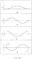
Figure 7A which shows plot of the first three derivatives of displacement for the simple harmonic function corresponding to the curve reveals that the plots of acceleration A and jerk J evidence discontinuities which theoretically represent infinite values of acceleration. Corresponding accelerations and jerk would impose destructive loadings and excessive noise, and leading to progressively variable performance and perhaps early failure of a torque limiter using such a shape for an engagement surface. This is despite the gradual appearance of the gentle curved shape of an engagement surface according to a simple harmonic function. -
Figure 7B shows plots of the three derivatives of the cycloidal function plot, revealing such discontinuities in the jerk plot, which have it also been determined to create unacceptable loadings and noise. -
Figure 7C shows the plots of the derivatives of seventh power polynomial, revealing that no such discontinuities occur, and this shape would allow a torque limiter to operate continuously in a released mode at relatively high speed, i.e., on the order of 1500 - 1800 rpm, without damage or changing release and reset torque levels. -
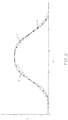
Figure 8A is a plot of displacement versus angular position, according to the eighth power polynomial equation:
- The precise shape of curvature of the engagement surface is critical for a resettable torque limiter which is operated at relatively high speeds when in a released condition. While it has long been assumed by torque limiter designers that providing a smooth curvature of the engagement surface should suffice, resettable torque limiters have heretofore never been successfully able to operate at high speed in a released mode for extended periods.
- The reason is that simply providing a smooth curvature is not sufficient as there are dynamic effects which are not apparent. Referring to
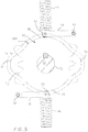
Figure 5 , theengagement surface 30A of arotary drive member 30 driven by aninput shaft 32 has two oppositely located lobes orundulations 34 extending out from a constant diameterperipheral engagement surface 36. - A pair of
rocker arms 38 pivotally mounted at 40 supported respective engagement elements comprised ofrollers 42 urged into engagement with theengagement surface 36 by associated springs 44. - The path traced by broken line L-1 represents the displacement of the center line of the
rollers 42 as themember 30 rotates, reflecting the smooth curvature of theengagement surface 36. - However, the radial acceleration of the
rollers 42, represented by broken line L-2 shows that acceleration of therollers 42 sharply varies as therollers 42 are displaced by theengagement surface 30A of thedrive member 30. - Smooth appearing curves can produce dynamic loading by the theoretical development of infinite or near infinite accelerations and/or jerk at transition points on the engagement surface curvature.
- A curvature which avoid such discontinuities is shaped as a plot of a polynomial of at least 5th power, including the seventh power, but most preferred is the plot of the eighth power.
Figure 8A shows a plot of such an eighth power polynomial curve. - The points 1-7 correspond to:
- 1. Transition from Dwell to Rise
- 2. Maximum Acceleration
- 3. Maximum Negative Acceleration
- 4. Maximum Displacement
- 5. Maximum Negative Acceleration
- 6. Maximum Acceleration
- 7. Transition from Fall to Dwell
- These are repeated for travel over each lobe.
-
Figure 8B is a plot of the first derivative (velocity) of the function ofFigure 8A .
- Points 1-7 correspond to:
- 1. Increase in Vertical Velocity
- 2. Rise-Maximum Increasing Velocity Slope
- 3. Rise Maximum Decreasing Velocity Slope
- 4. Zero Velocity
- 5. Fall-Maximum Increasing Velocity Slope
- 6. Fall Maximum Decreasing Velocity Slope
- 7. Back to Dwell Rest
-
Figure 8C is a plot of the second derivative (acceleration) of the function ofFigure 8A :
-
Figure 8D is a plot of the third derivative (jerk) of the function ofFigure 8A :
- Thus, an engagement surface formed in conformity to a plot of an eight power polynomial function above will provide a torque limiter which can operate continuously in the released condition at high motor speeds without overstressing the parts leading to noise, and changing release torque levels, and complete failures.
- Each particular application with a desired torque release set point and particulars as to the geometry of the various parts will reflect the actual dimensions of the curve of the engagement surface.
Claims (7)
- A torque limiter arrangement (10) for interrupting a rotary drive between two rotary members (12, 14) rotating at high speeds by disconnecting the two members (12, 14) to overrun relative each other at a speed on the order of 1800 rpm or higher for extended time periods after the torque transmitted between said members (12, 14) exceeds a predetermined level, comprising:a curving engagement surface (16) formed on one rotary member (12) extending around an axis of rotation of said one member (12) having a plurality of peaks each comprising a drive lobe (16A);a plurality of engagement element assemblies (18) carried by another of said rotary members (14) each including an engagement element spring (26) urged into contact with said engagement surface (16) by a spring arrangement acting radially on said engagement element (20), producing an increasing resistance force as said engagement element (20) is caused to partially ascend a respective lobe (16A) by said relative rotation between said members (12, 14) caused by the transmission of torque therebetween any over a preset limit, torque applied by one of said rotary members (12, 14) below said preset limit being insufficient to overcome said spring arrangement and not causing said engagement element (20) to pass over said lobe (16A) and to thereby maintain a driving connection between said rotary members (12, 14); and, wherein whenever a transmitted torque increases over said preset limit causing said one or more follower elements (20) to be moved past and over said lobes (16A) whereby said rotary driving relationship between said rotary members (12, 14) is interrupted by said engagement elements (20) passing over said one or more lobes (16A) to disconnect said driving relationship between said members (12, 14) until said applied torque again declines below said preset limit to reset said torque limiter by again preventing said engagement elements (20) from rotating past an adjacent one or more lobe (16A) to thereby re-establish a rotary driving relationship between said rotary members (12, 14), said lobes (16A) of said engagement surface (16) of a curved shape insuring that discontinuities in a plot of the acceleration or jerk derivatives of the shape said lobes (16A) of said engagement surface (16) do not occur anywhere along said plot as said engagement elements (20) pass over said lobes (16A),characterized in that each of said engagement surface peaks being defined at least in part by curved shape of a plot of a polynomial function of at least the fifth power, thereby minimizing dynamic forces imposed on said engagement elements (20) or engagement surface (16) when said torque limiter is operating in a rotary member disconnected condition.
- The torque limiter according to claim 1 wherein said engagement surface lobes (16A) are defined at least in part in accordance with the curved shape of a plot of an eighth power polynomial function.
- A method of interrupting the transmission of torque between a pair of rotary drive members (12, 14) rotating at high speeds on the order of 1800 rpm or higher for extended periods comprising:interconnecting said members (12, 14) by a plurality of engagement elements (20) movably mounted on one of said members (12, 14) and applying an urging force tending to move said engagement elements (20) into engagement with an engagement surface (16) of revolution centered on an axis of rotation of said members (12, 14) formed on the other of said members (14, 12),said engagement surface (16) formed with a series of curved lobes (16A) of increasing heights in the same direction as the direction of movement of said plurality of engagement elements (20) which cause an increase in the urging force exerted on said engagement elements (20) as said elements (20) each ascend a respective one of said lobes (16A) to cause said elements (20) to maintain a driving connection between said members (12, 14) as long as applied torque levels do not exceed a preset level necessary to overcome said urging force sufficiently to allow said engagement elements (20) to completely ascend and pass by said lobes (16A);said transmission of torques interrupted when said applied torque levels exceed said preset levels,characterized by configuring said engagement surface lobes (16A) to be shaped in accordance with a curved shape plot of a fifth or greater power polynomial function so as to not produce discontinuities in acceleration and/or jerk values when said lobes (16A) are overrun by said engagement elements (20).
- The method according to claim 3 wherein said lobes (16A) are defined at least in part in accordance with the curved shape of a plot of a seventh or greater power polynomial function.
- The method according to claim 3 wherein said lobes (16A) are defined at least in part in accordance with the curved shape of a plot of an eighth power polynomial
- The method according to claim 3 including mounting said engagement rollers (20) comprising said engagement elements on said one member so as to be urged to engage said engagement surface (16).
- The method according to claim 3 further including mounting each of said rollers (20) on a respective rocker arm (22) which are pivoted on said one of said members (14).
Applications Claiming Priority (2)
| Application Number | Priority Date | Filing Date | Title |
|---|---|---|---|
| US13/531,633 US8696473B2 (en) | 2008-06-10 | 2012-06-25 | Automatic resetting torque limiter capable of high speed continuous operations in released mode |
| PCT/US2013/044416 WO2014004015A1 (en) | 2012-06-25 | 2013-06-06 | Automatic resetting torque limiter capable of high speed continuous operation in released mode |
Publications (3)
| Publication Number | Publication Date |
|---|---|
| EP2864672A1 EP2864672A1 (en) | 2015-04-29 |
| EP2864672A4 EP2864672A4 (en) | 2016-10-12 |
| EP2864672B1 true EP2864672B1 (en) | 2018-08-01 |
Family
ID=49783743
Family Applications (1)
| Application Number | Title | Priority Date | Filing Date |
|---|---|---|---|
| EP13809546.8A Not-in-force EP2864672B1 (en) | 2012-06-25 | 2013-06-06 | Automatic resetting torque limiter capable of high speed continuous operation in released mode |
Country Status (2)
| Country | Link |
|---|---|
| EP (1) | EP2864672B1 (en) |
| WO (1) | WO2014004015A1 (en) |
Family Cites Families (6)
| Publication number | Priority date | Publication date | Assignee | Title |
|---|---|---|---|---|
| US2501648A (en) | 1945-02-15 | 1950-03-21 | Guy G Ogden | Clutch |
| US4271944A (en) * | 1979-02-12 | 1981-06-09 | Hanson Douglas R | Single revolution torque limiting clutch |
| GB2265191A (en) * | 1992-03-18 | 1993-09-22 | Yang Tai Her | Centrifugal clutch |
| JP2006138422A (en) * | 2004-11-12 | 2006-06-01 | Fujikin Inc | Handle with torque limiter and fluid controller having this handle |
| JP2008008438A (en) * | 2006-06-30 | 2008-01-17 | Ntn Corp | One-way intermittent feeding unit |
| US20090305794A1 (en) | 2008-06-10 | 2009-12-10 | Long Jr Thomas F | Automatic Resetting Mechanical Torque Limiting Clutch |
-
2013
- 2013-06-06 WO PCT/US2013/044416 patent/WO2014004015A1/en not_active Ceased
- 2013-06-06 EP EP13809546.8A patent/EP2864672B1/en not_active Not-in-force
Non-Patent Citations (1)
| Title |
|---|
| None * |
Also Published As
| Publication number | Publication date |
|---|---|
| EP2864672A4 (en) | 2016-10-12 |
| WO2014004015A1 (en) | 2014-01-03 |
| EP2864672A1 (en) | 2015-04-29 |
| WO2014004015A4 (en) | 2014-02-27 |
Similar Documents
| Publication | Publication Date | Title |
|---|---|---|
| US9054560B2 (en) | Power generating apparatus | |
| WO2010005880A1 (en) | Cam damped pulley for rotary devices | |
| WO2008010052A2 (en) | Power transmission device | |
| CN102817936B (en) | Spring friction clutch mechanism for belt pulley and one-way coupling damping belt pulley | |
| CN113202886B (en) | A Gear Clutch Mechanism with Automatic Adjustment of Protection Threshold | |
| CN108930781B (en) | Transmission mechanism | |
| US20090305794A1 (en) | Automatic Resetting Mechanical Torque Limiting Clutch | |
| US8696473B2 (en) | Automatic resetting torque limiter capable of high speed continuous operations in released mode | |
| EP2989340B1 (en) | Wind turbine coupling to mitigate torque reversals | |
| CN103912656B (en) | Damping type gear | |
| WO2014004015A1 (en) | Automatic resetting torque limiter capable of high speed continuous operation in released mode | |
| CN202790444U (en) | One-way coupling shock-absorption belt pulley adopting spring frication braking | |
| CN101520081B (en) | Automatic directional driving mechanism | |
| CN105587797B (en) | Space wedging type overrunning belt pulley capable of reducing torsional vibration and overrunning clutch | |
| CN108930782B (en) | Transmission mechanism based on gear adjustment | |
| CN110873152A (en) | A buffer connection mechanism of a transmission shaft | |
| JP5816895B2 (en) | Fluid friction transmission force limiter | |
| JP4894574B2 (en) | Pulley unit | |
| CN201246426Y (en) | Exterior star wheel type loader two-shaft assembly | |
| JP2005337398A (en) | Power transmission device | |
| RU159552U1 (en) | HYDRODYNAMIC LOCKABLE SAFETY CLUTCH | |
| CN114263725A (en) | New energy automobile is fixed bolster for reduction gear | |
| CN112747087A (en) | Planetary gear system, torsion safety device and method for operating transmission system | |
| CN201155534Y (en) | an overrunning clutch | |
| CN220816340U (en) | Pneumatic one-way overrunning clutch |
Legal Events
| Date | Code | Title | Description |
|---|---|---|---|
| PUAI | Public reference made under article 153(3) epc to a published international application that has entered the european phase |
Free format text: ORIGINAL CODE: 0009012 |
|
| 17P | Request for examination filed |
Effective date: 20150102 |
|
| AK | Designated contracting states |
Kind code of ref document: A1 Designated state(s): AL AT BE BG CH CY CZ DE DK EE ES FI FR GB GR HR HU IE IS IT LI LT LU LV MC MK MT NL NO PL PT RO RS SE SI SK SM TR |
|
| AX | Request for extension of the european patent |
Extension state: BA ME |
|
| DAX | Request for extension of the european patent (deleted) | ||
| RA4 | Supplementary search report drawn up and despatched (corrected) |
Effective date: 20160914 |
|
| RIC1 | Information provided on ipc code assigned before grant |
Ipc: F16D 7/02 20060101ALI20160908BHEP Ipc: F16D 43/20 20060101ALI20160908BHEP Ipc: F16H 35/10 20060101AFI20160908BHEP |
|
| GRAP | Despatch of communication of intention to grant a patent |
Free format text: ORIGINAL CODE: EPIDOSNIGR1 |
|
| STAA | Information on the status of an ep patent application or granted ep patent |
Free format text: STATUS: GRANT OF PATENT IS INTENDED |
|
| INTG | Intention to grant announced |
Effective date: 20180103 |
|
| GRAS | Grant fee paid |
Free format text: ORIGINAL CODE: EPIDOSNIGR3 |
|
| GRAA | (expected) grant |
Free format text: ORIGINAL CODE: 0009210 |
|
| STAA | Information on the status of an ep patent application or granted ep patent |
Free format text: STATUS: THE PATENT HAS BEEN GRANTED |
|
| AK | Designated contracting states |
Kind code of ref document: B1 Designated state(s): AL AT BE BG CH CY CZ DE DK EE ES FI FR GB GR HR HU IE IS IT LI LT LU LV MC MK MT NL NO PL PT RO RS SE SI SK SM TR |
|
| REG | Reference to a national code |
Ref country code: GB Ref legal event code: FG4D |
|
| REG | Reference to a national code |
Ref country code: CH Ref legal event code: EP Ref country code: AT Ref legal event code: REF Ref document number: 1024668 Country of ref document: AT Kind code of ref document: T Effective date: 20180815 |
|
| REG | Reference to a national code |
Ref country code: IE Ref legal event code: FG4D |
|
| REG | Reference to a national code |
Ref country code: DE Ref legal event code: R096 Ref document number: 602013041299 Country of ref document: DE |
|
| REG | Reference to a national code |
Ref country code: NL Ref legal event code: MP Effective date: 20180801 |
|
| REG | Reference to a national code |
Ref country code: LT Ref legal event code: MG4D |
|
| REG | Reference to a national code |
Ref country code: AT Ref legal event code: MK05 Ref document number: 1024668 Country of ref document: AT Kind code of ref document: T Effective date: 20180801 |
|
| PG25 | Lapsed in a contracting state [announced via postgrant information from national office to epo] |
Ref country code: BG Free format text: LAPSE BECAUSE OF FAILURE TO SUBMIT A TRANSLATION OF THE DESCRIPTION OR TO PAY THE FEE WITHIN THE PRESCRIBED TIME-LIMIT Effective date: 20181101 Ref country code: NL Free format text: LAPSE BECAUSE OF FAILURE TO SUBMIT A TRANSLATION OF THE DESCRIPTION OR TO PAY THE FEE WITHIN THE PRESCRIBED TIME-LIMIT Effective date: 20180801 Ref country code: PL Free format text: LAPSE BECAUSE OF FAILURE TO SUBMIT A TRANSLATION OF THE DESCRIPTION OR TO PAY THE FEE WITHIN THE PRESCRIBED TIME-LIMIT Effective date: 20180801 Ref country code: LT Free format text: LAPSE BECAUSE OF FAILURE TO SUBMIT A TRANSLATION OF THE DESCRIPTION OR TO PAY THE FEE WITHIN THE PRESCRIBED TIME-LIMIT Effective date: 20180801 Ref country code: RS Free format text: LAPSE BECAUSE OF FAILURE TO SUBMIT A TRANSLATION OF THE DESCRIPTION OR TO PAY THE FEE WITHIN THE PRESCRIBED TIME-LIMIT Effective date: 20180801 Ref country code: IS Free format text: LAPSE BECAUSE OF FAILURE TO SUBMIT A TRANSLATION OF THE DESCRIPTION OR TO PAY THE FEE WITHIN THE PRESCRIBED TIME-LIMIT Effective date: 20181201 Ref country code: AT Free format text: LAPSE BECAUSE OF FAILURE TO SUBMIT A TRANSLATION OF THE DESCRIPTION OR TO PAY THE FEE WITHIN THE PRESCRIBED TIME-LIMIT Effective date: 20180801 Ref country code: NO Free format text: LAPSE BECAUSE OF FAILURE TO SUBMIT A TRANSLATION OF THE DESCRIPTION OR TO PAY THE FEE WITHIN THE PRESCRIBED TIME-LIMIT Effective date: 20181101 Ref country code: FI Free format text: LAPSE BECAUSE OF FAILURE TO SUBMIT A TRANSLATION OF THE DESCRIPTION OR TO PAY THE FEE WITHIN THE PRESCRIBED TIME-LIMIT Effective date: 20180801 Ref country code: GR Free format text: LAPSE BECAUSE OF FAILURE TO SUBMIT A TRANSLATION OF THE DESCRIPTION OR TO PAY THE FEE WITHIN THE PRESCRIBED TIME-LIMIT Effective date: 20181102 Ref country code: SE Free format text: LAPSE BECAUSE OF FAILURE TO SUBMIT A TRANSLATION OF THE DESCRIPTION OR TO PAY THE FEE WITHIN THE PRESCRIBED TIME-LIMIT Effective date: 20180801 |
|
| PG25 | Lapsed in a contracting state [announced via postgrant information from national office to epo] |
Ref country code: HR Free format text: LAPSE BECAUSE OF FAILURE TO SUBMIT A TRANSLATION OF THE DESCRIPTION OR TO PAY THE FEE WITHIN THE PRESCRIBED TIME-LIMIT Effective date: 20180801 Ref country code: AL Free format text: LAPSE BECAUSE OF FAILURE TO SUBMIT A TRANSLATION OF THE DESCRIPTION OR TO PAY THE FEE WITHIN THE PRESCRIBED TIME-LIMIT Effective date: 20180801 Ref country code: LV Free format text: LAPSE BECAUSE OF FAILURE TO SUBMIT A TRANSLATION OF THE DESCRIPTION OR TO PAY THE FEE WITHIN THE PRESCRIBED TIME-LIMIT Effective date: 20180801 |
|
| PG25 | Lapsed in a contracting state [announced via postgrant information from national office to epo] |
Ref country code: EE Free format text: LAPSE BECAUSE OF FAILURE TO SUBMIT A TRANSLATION OF THE DESCRIPTION OR TO PAY THE FEE WITHIN THE PRESCRIBED TIME-LIMIT Effective date: 20180801 Ref country code: IT Free format text: LAPSE BECAUSE OF FAILURE TO SUBMIT A TRANSLATION OF THE DESCRIPTION OR TO PAY THE FEE WITHIN THE PRESCRIBED TIME-LIMIT Effective date: 20180801 Ref country code: CZ Free format text: LAPSE BECAUSE OF FAILURE TO SUBMIT A TRANSLATION OF THE DESCRIPTION OR TO PAY THE FEE WITHIN THE PRESCRIBED TIME-LIMIT Effective date: 20180801 Ref country code: RO Free format text: LAPSE BECAUSE OF FAILURE TO SUBMIT A TRANSLATION OF THE DESCRIPTION OR TO PAY THE FEE WITHIN THE PRESCRIBED TIME-LIMIT Effective date: 20180801 Ref country code: ES Free format text: LAPSE BECAUSE OF FAILURE TO SUBMIT A TRANSLATION OF THE DESCRIPTION OR TO PAY THE FEE WITHIN THE PRESCRIBED TIME-LIMIT Effective date: 20180801 |
|
| REG | Reference to a national code |
Ref country code: DE Ref legal event code: R097 Ref document number: 602013041299 Country of ref document: DE |
|
| PG25 | Lapsed in a contracting state [announced via postgrant information from national office to epo] |
Ref country code: SM Free format text: LAPSE BECAUSE OF FAILURE TO SUBMIT A TRANSLATION OF THE DESCRIPTION OR TO PAY THE FEE WITHIN THE PRESCRIBED TIME-LIMIT Effective date: 20180801 Ref country code: DK Free format text: LAPSE BECAUSE OF FAILURE TO SUBMIT A TRANSLATION OF THE DESCRIPTION OR TO PAY THE FEE WITHIN THE PRESCRIBED TIME-LIMIT Effective date: 20180801 Ref country code: SK Free format text: LAPSE BECAUSE OF FAILURE TO SUBMIT A TRANSLATION OF THE DESCRIPTION OR TO PAY THE FEE WITHIN THE PRESCRIBED TIME-LIMIT Effective date: 20180801 |
|
| PLBE | No opposition filed within time limit |
Free format text: ORIGINAL CODE: 0009261 |
|
| STAA | Information on the status of an ep patent application or granted ep patent |
Free format text: STATUS: NO OPPOSITION FILED WITHIN TIME LIMIT |
|
| 26N | No opposition filed |
Effective date: 20190503 |
|
| PG25 | Lapsed in a contracting state [announced via postgrant information from national office to epo] |
Ref country code: SI Free format text: LAPSE BECAUSE OF FAILURE TO SUBMIT A TRANSLATION OF THE DESCRIPTION OR TO PAY THE FEE WITHIN THE PRESCRIBED TIME-LIMIT Effective date: 20180801 |
|
| PGFP | Annual fee paid to national office [announced via postgrant information from national office to epo] |
Ref country code: FR Payment date: 20190625 Year of fee payment: 7 |
|
| PGFP | Annual fee paid to national office [announced via postgrant information from national office to epo] |
Ref country code: GB Payment date: 20190624 Year of fee payment: 7 Ref country code: DE Payment date: 20190725 Year of fee payment: 7 |
|
| PG25 | Lapsed in a contracting state [announced via postgrant information from national office to epo] |
Ref country code: MC Free format text: LAPSE BECAUSE OF FAILURE TO SUBMIT A TRANSLATION OF THE DESCRIPTION OR TO PAY THE FEE WITHIN THE PRESCRIBED TIME-LIMIT Effective date: 20180801 |
|
| REG | Reference to a national code |
Ref country code: CH Ref legal event code: PL |
|
| REG | Reference to a national code |
Ref country code: BE Ref legal event code: MM Effective date: 20190630 |
|
| PG25 | Lapsed in a contracting state [announced via postgrant information from national office to epo] |
Ref country code: TR Free format text: LAPSE BECAUSE OF FAILURE TO SUBMIT A TRANSLATION OF THE DESCRIPTION OR TO PAY THE FEE WITHIN THE PRESCRIBED TIME-LIMIT Effective date: 20180801 |
|
| PG25 | Lapsed in a contracting state [announced via postgrant information from national office to epo] |
Ref country code: IE Free format text: LAPSE BECAUSE OF NON-PAYMENT OF DUE FEES Effective date: 20190606 |
|
| PG25 | Lapsed in a contracting state [announced via postgrant information from national office to epo] |
Ref country code: LI Free format text: LAPSE BECAUSE OF NON-PAYMENT OF DUE FEES Effective date: 20190630 Ref country code: CH Free format text: LAPSE BECAUSE OF NON-PAYMENT OF DUE FEES Effective date: 20190630 Ref country code: BE Free format text: LAPSE BECAUSE OF NON-PAYMENT OF DUE FEES Effective date: 20190630 Ref country code: LU Free format text: LAPSE BECAUSE OF NON-PAYMENT OF DUE FEES Effective date: 20190606 |
|
| PG25 | Lapsed in a contracting state [announced via postgrant information from national office to epo] |
Ref country code: PT Free format text: LAPSE BECAUSE OF FAILURE TO SUBMIT A TRANSLATION OF THE DESCRIPTION OR TO PAY THE FEE WITHIN THE PRESCRIBED TIME-LIMIT Effective date: 20181201 |
|
| REG | Reference to a national code |
Ref country code: DE Ref legal event code: R119 Ref document number: 602013041299 Country of ref document: DE |
|
| GBPC | Gb: european patent ceased through non-payment of renewal fee |
Effective date: 20200606 |
|
| PG25 | Lapsed in a contracting state [announced via postgrant information from national office to epo] |
Ref country code: GB Free format text: LAPSE BECAUSE OF NON-PAYMENT OF DUE FEES Effective date: 20200606 Ref country code: FR Free format text: LAPSE BECAUSE OF NON-PAYMENT OF DUE FEES Effective date: 20200630 |
|
| PG25 | Lapsed in a contracting state [announced via postgrant information from national office to epo] |
Ref country code: CY Free format text: LAPSE BECAUSE OF FAILURE TO SUBMIT A TRANSLATION OF THE DESCRIPTION OR TO PAY THE FEE WITHIN THE PRESCRIBED TIME-LIMIT Effective date: 20180801 Ref country code: DE Free format text: LAPSE BECAUSE OF NON-PAYMENT OF DUE FEES Effective date: 20210101 |
|
| PG25 | Lapsed in a contracting state [announced via postgrant information from national office to epo] |
Ref country code: MT Free format text: LAPSE BECAUSE OF FAILURE TO SUBMIT A TRANSLATION OF THE DESCRIPTION OR TO PAY THE FEE WITHIN THE PRESCRIBED TIME-LIMIT Effective date: 20180801 Ref country code: HU Free format text: LAPSE BECAUSE OF FAILURE TO SUBMIT A TRANSLATION OF THE DESCRIPTION OR TO PAY THE FEE WITHIN THE PRESCRIBED TIME-LIMIT; INVALID AB INITIO Effective date: 20130606 |
|
| PG25 | Lapsed in a contracting state [announced via postgrant information from national office to epo] |
Ref country code: MK Free format text: LAPSE BECAUSE OF FAILURE TO SUBMIT A TRANSLATION OF THE DESCRIPTION OR TO PAY THE FEE WITHIN THE PRESCRIBED TIME-LIMIT Effective date: 20180801 |