EP2864012B1 - Phase separation element and phase separation device - Google Patents
Phase separation element and phase separation device Download PDFInfo
- Publication number
- EP2864012B1 EP2864012B1 EP13726803.3A EP13726803A EP2864012B1 EP 2864012 B1 EP2864012 B1 EP 2864012B1 EP 13726803 A EP13726803 A EP 13726803A EP 2864012 B1 EP2864012 B1 EP 2864012B1
- Authority
- EP
- European Patent Office
- Prior art keywords
- phase separation
- separation element
- receptacle
- phase
- hydrophobic
- Prior art date
- Legal status (The legal status is an assumption and is not a legal conclusion. Google has not performed a legal analysis and makes no representation as to the accuracy of the status listed.)
- Not-in-force
Links
Images


Classifications
-
- B—PERFORMING OPERATIONS; TRANSPORTING
- B01—PHYSICAL OR CHEMICAL PROCESSES OR APPARATUS IN GENERAL
- B01D—SEPARATION
- B01D11/00—Solvent extraction
- B01D11/04—Solvent extraction of solutions which are liquid
- B01D11/0415—Solvent extraction of solutions which are liquid in combination with membranes
-
- B—PERFORMING OPERATIONS; TRANSPORTING
- B01—PHYSICAL OR CHEMICAL PROCESSES OR APPARATUS IN GENERAL
- B01D—SEPARATION
- B01D29/00—Filters with filtering elements stationary during filtration, e.g. pressure or suction filters, not covered by groups B01D24/00 - B01D27/00; Filtering elements therefor
- B01D29/11—Filters with filtering elements stationary during filtration, e.g. pressure or suction filters, not covered by groups B01D24/00 - B01D27/00; Filtering elements therefor with bag, cage, hose, tube, sleeve or like filtering elements
- B01D29/31—Self-supporting filtering elements
- B01D29/33—Self-supporting filtering elements arranged for inward flow filtration
- B01D29/336—Self-supporting filtering elements arranged for inward flow filtration open-ended, the arrival of the mixture to be filtered and the discharge of the concentrated mixture are situated on both opposite sides of the filtering element
-
- B—PERFORMING OPERATIONS; TRANSPORTING
- B01—PHYSICAL OR CHEMICAL PROCESSES OR APPARATUS IN GENERAL
- B01D—SEPARATION
- B01D17/00—Separation of liquids, not provided for elsewhere, e.g. by thermal diffusion
- B01D17/02—Separation of non-miscible liquids
-
- B—PERFORMING OPERATIONS; TRANSPORTING
- B01—PHYSICAL OR CHEMICAL PROCESSES OR APPARATUS IN GENERAL
- B01D—SEPARATION
- B01D17/00—Separation of liquids, not provided for elsewhere, e.g. by thermal diffusion
- B01D17/08—Thickening liquid suspensions by filtration
- B01D17/085—Thickening liquid suspensions by filtration with membranes
-
- B—PERFORMING OPERATIONS; TRANSPORTING
- B01—PHYSICAL OR CHEMICAL PROCESSES OR APPARATUS IN GENERAL
- B01D—SEPARATION
- B01D29/00—Filters with filtering elements stationary during filtration, e.g. pressure or suction filters, not covered by groups B01D24/00 - B01D27/00; Filtering elements therefor
- B01D29/50—Filters with filtering elements stationary during filtration, e.g. pressure or suction filters, not covered by groups B01D24/00 - B01D27/00; Filtering elements therefor with multiple filtering elements, characterised by their mutual disposition
- B01D29/52—Filters with filtering elements stationary during filtration, e.g. pressure or suction filters, not covered by groups B01D24/00 - B01D27/00; Filtering elements therefor with multiple filtering elements, characterised by their mutual disposition in parallel connection
-
- B—PERFORMING OPERATIONS; TRANSPORTING
- B01—PHYSICAL OR CHEMICAL PROCESSES OR APPARATUS IN GENERAL
- B01D—SEPARATION
- B01D69/00—Semi-permeable membranes for separation processes or apparatus characterised by their form, structure or properties; Manufacturing processes specially adapted therefor
- B01D69/04—Tubular membranes
- B01D69/046—Tubular membranes characterised by the cross-sectional shape of the tube
-
- B—PERFORMING OPERATIONS; TRANSPORTING
- B01—PHYSICAL OR CHEMICAL PROCESSES OR APPARATUS IN GENERAL
- B01D—SEPARATION
- B01D71/00—Semi-permeable membranes for separation processes or apparatus characterised by the material; Manufacturing processes specially adapted therefor
- B01D71/06—Organic material
- B01D71/26—Polyalkenes
- B01D71/261—Polyethylene
-
- B—PERFORMING OPERATIONS; TRANSPORTING
- B01—PHYSICAL OR CHEMICAL PROCESSES OR APPARATUS IN GENERAL
- B01D—SEPARATION
- B01D71/00—Semi-permeable membranes for separation processes or apparatus characterised by the material; Manufacturing processes specially adapted therefor
- B01D71/06—Organic material
- B01D71/26—Polyalkenes
- B01D71/262—Polypropylene
-
- B—PERFORMING OPERATIONS; TRANSPORTING
- B01—PHYSICAL OR CHEMICAL PROCESSES OR APPARATUS IN GENERAL
- B01D—SEPARATION
- B01D71/00—Semi-permeable membranes for separation processes or apparatus characterised by the material; Manufacturing processes specially adapted therefor
- B01D71/06—Organic material
- B01D71/30—Polyalkenyl halides
- B01D71/32—Polyalkenyl halides containing fluorine atoms
- B01D71/36—Polytetrafluoroethylene
-
- B—PERFORMING OPERATIONS; TRANSPORTING
- B01—PHYSICAL OR CHEMICAL PROCESSES OR APPARATUS IN GENERAL
- B01D—SEPARATION
- B01D2313/00—Details relating to membrane modules or apparatus
- B01D2313/02—Specific tightening or locking mechanisms
- B01D2313/025—Specific membrane holders
-
- B—PERFORMING OPERATIONS; TRANSPORTING
- B01—PHYSICAL OR CHEMICAL PROCESSES OR APPARATUS IN GENERAL
- B01D—SEPARATION
- B01D2313/00—Details relating to membrane modules or apparatus
- B01D2313/04—Specific sealing means
-
- B—PERFORMING OPERATIONS; TRANSPORTING
- B01—PHYSICAL OR CHEMICAL PROCESSES OR APPARATUS IN GENERAL
- B01D—SEPARATION
- B01D2325/00—Details relating to properties of membranes
- B01D2325/38—Hydrophobic membranes
Definitions
- the present invention relates generally to the field of phase separation, and more particularly to a phase separation device comprising a phase separation element.
- Phase separation is a type of liquid-liquid extraction and is a method of processing and purifying samples.
- Traditional phase separators are cartridge products that separate one of two immiscible liquid phases when the lower phase is organic and the upper phase is aqueous. Because of their general function, phase separators find application in a variety of different applications and markets. Phase separators are predominantly used in a chemistry environment in a variety of different applications, ranging from crude reaction work-up to preparation of samples or intermediates for synthetic programs, and a number of environmentally sensitive applications can also be captured.
- the key to the separation of the two liquids is in the design of the frit material used in the cartridges.
- the main limitation of traditional phase separators is that they only work when the organic layer is on the bottom, i.e. the aqueous layer sits on top. This typically only occurs when organic samples are extracted into chlorinated (heavy) solvents. The mixture is transferred to the phase separator, and only the lower organic layer is allowed to pass through the cartridge.
- the frit is thus impervious to aqueous solvents, but allows passage of chlorinated solvents.
- the traditional separator is designed to rapidly separate chlorinated and aqueous solvents under gravity. No vacuum or positive pressure is required.
- the device comprises a tubular member which has an opening in the wall, which opening is covered by a water impermeable hydrophobic membrane.
- the tubular member is loosely fitted in an outer tube having a discharge outlet at the bottom.
- a mixture of water and organic solvent contained in the tubular member will be separated as the organic solvent can pass through the membrane from the inside to the outside while the water is retained in the tubular member.
- the membrane may be in the form of a membrane filter having a pore size of 0.1 to 2 ⁇ m.
- the membrane may alternatively be processed by spraying silicone or Teflon on the surface of solvent insoluble fibre to make it hydrophobic.
- the object of the present invention is to provide a more efficient, easy-to-use phase separator than those already known in the art for separating a biphasic aqueous and organic liquid system irrespective of which liquid is heavier.
- An aim of the present invention is to enable separation of two immiscible liquid phases where the organic layer is lighter than the aqueous layer, such as when mixing water with an organic solvent selected from hexane, ethyl acetate, petroleum ethers, diethyl ether, or toluene.
- the present invention also enables separation where the organic liquid is heavier that the aqueous liquid, i.e. it provides a universal solution for both heavier and lighter organic liquids.
- phase separator which has a capacity to separate dispersions or shaken suspensions, and a phase separator, in which the mixture does not need to stand to separate, i.e. which can operate in continuous mode.
- the present invention relates to a phase separation device including a phase separation element, comprising a porous and hydrophobic material, wherein the phase separation element is a solid cylinder having a first end and a second end.
- the phase separation element consists of a porous and hydrophobic material.
- the porous and hydrophobic material allows hydrophobic liquid to pass through the phase separation element, while the material prevents (or at least delays) non-hydrophobic liquids from entering and passing through the material.
- Another term for the phase separation element is "frit", which is often used in the technical field of phase separation.
- phase separation element is closed at the second end of the cylinder. In an alternative embodiment, the phase separation element is open at the second end of the cylinder.
- phase separation element in which the cylinder is solid, i.e. without a lumen. Nevertheless, hydrophobic liquid will pass through the phase separation element due to the porous structure of the hydrophobic material of the phase separation element.
- the phase separation element consists of a porous and hydrophobic polymer material, which can be obtained from manufacturers such as Filtrona, Porvair and Porex.
- the porous and hydrophobic material can be selected from for example polyethylene, polypropylene and polytetrafluoroethylene (PTFE).
- the invention provides a vertically oriented phase separation device comprising a receptacle having an outlet portion comprising an outlet opening, and a phase separation element consisting of a porous and hydrophobic material, wherein the phase separation element is a solid cylinder without a lumen having a first end and a second end, wherein the phase separation element is in fluid communication with the outlet opening of the receptacle, and wherein the phase separation element is adapted to fit tight in the outlet portion of the receptacle such that no fluid present in the receptacle outside of the phase element can run through the outlet opening.
- the phase separation element consists of a porous and hydrophobic material.
- the phase separation device comprises a receptacle having a bottom portion, and a phase separation element comprising a porous and hydrophobic material, wherein the bottom portion has an inner surface and optionally has an outlet portion comprising an outlet opening, wherein the phase separation element is a cylinder having a first end and a second end and a base surface comprising at least three circumferential points that are adapted to contact the inner surface of the bottom portion of the receptacle, and that the base surface of the cylinder has a different shape than the cross section area of the bottom portion, and that the phase separation element is adapted to fit in the bottom portion by connection between the inner surface of the bottom portion and the at least three circumferential points of the base surface of the cylinder.
- the phase separation element consists of a porous and hydrophobic material.
- the outlet portion of the receptacle comprises an insert, which has an inlet end having an inlet opening and an outlet end having an outlet opening, wherein the inlet end of the insert is adapted to fit tight in the outlet portion of the receptacle, and wherein the phase separation element is adapted to fit tight in the inlet opening of the insert, and wherein the phase separation element is in fluid communication with the outlet opening of the insert.
- the outlet portion of the receptacle further comprises a second outlet opening, which is separated from the outlet opening described above.
- the present invention relates to a phase separation device including a phase separation element consisting of a porous and hydrophobic material, wherein the phase separation element is a cylinder having a first end 2 and a second end 3.
- the term "cylinder” is defined as a three-dimensional space geometric body (unknown inner) delimited by two identical, parallel spaced planar surfaces (base surfaces) and the envelope surface formed as a line connecting the corresponding points on both base surfaces can run along the base surfaces' entire circumference.
- the flat surface can be used as a base, and parallel displacement can have any angle to the base surface.
- the perpendicular distance between the surfaces is called height of the cylinder.
- the base surface can have any form. If the base surface is a circle, the cylinder is called a circular cylinder.
- the phase separation element is a circular cylinder.
- the phase separation element 1 further has an outlet portion 5 having an outlet opening 16 at the first end 2 of the cylinder.
- the outlet portion 5 of the cylinder has a smaller outer diameter than the outer diameter of the second end 3 and the rest of the cylinder.
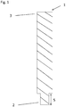
- fig. 1 shows an the phase separation element of the device according to the invention, consisting of a porous and hydrophobic material, wherein the phase separation element 1 is a cylinder having a first end 2 and a second end 3, and wherein the cylinder is solid.
- the phase separation element has an outlet portion 5 at the first end 2.
- the outlet portion 5 of the cylinder suitably has a smaller outer diameter than the outer diameter of the second end 3 and the rest of the cylinder.
- phase separation element shown in fig. 1 is suitable for the separation of a mixture of immiscible liquids, where the mixture is provided outside of the phase separation element and the hydrophobic liquid is allowed to pass through the phase separation element from the outside to the inside, while the non-hydrophobic liquid is retained outside of the phase separation element.
- the porous and hydrophobic material of the phase separation element has a pore size of above 2 ⁇ m and maximum 100 ⁇ m, such as about 5, 10, 15, 20, 50, 75 or 100 ⁇ m.
- the phase separation element which consists of a porous and hydrophobic polymer material, may be selected from for example polyethylene, polypropylene and polytetrafluoroethylene (PTFE).
- PTFE polytetrafluoroethylene
- the phase separation element is made of porous polyethylene material with a 10 ⁇ m pore size and a wall thickness of 1 mm.
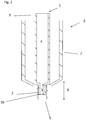
- Fig. 2 depicts a phase separation device 6 comprising a receptacle 7 having an outlet portion 8 comprising an outlet opening 9, and a phase separation element 1 consisting of a porous and hydrophobic material, wherein the phase separation element 1 is a cylinder having a first end 2 and a second end 3.
- the phase separation shown with a lumen 4 not according to the invention is in fluid communication with the outlet portion 8 of the receptacle 7, such that fluid passing through and exiting the phase separation element 1, via the outlet opening 16 of the outlet portion 5 at the first end 2 of the cylinder, can run through the outlet opening 9.
- the phase separation element 1 is adapted to fit tight in the outlet portion 8 of the receptacle 7, such that no fluid present in the receptacle 7, outside of the phase separation element 1, can run through the outlet opening 9 of the receptacle 7.
- the cylinder is tubular and has an outlet portion 5 having an outlet opening 16 at the first end 2 of the cylinder.
- the cylinder is solid, as depicted in fig.1 and thus replaces all cylinders shown with a lumen in fig.2-4 , 6 .
- the phase separation element 1 is in fluid communication with the outlet portion 8 of the receptacle 7, such that fluid passing through the solid cylinder of the phase separation element 1 and exiting the phase separation element 1, via the outlet portion 5 at the first end 2 of the cylinder, can run through the outlet opening 9 of the receptacle.
- the phase separation element 1 is adapted to fit tight in the outlet portion 8 of the receptacle 7, such that no fluid present in the receptacle 7, outside of the phase separation element 1, can run through the outlet opening 9 of the receptacle 7.
- the tight fit of the phase separation element 1 in the outlet portion 8 of the receptacle 7 may be obtained by choosing the same shape of the base surface of cylinder of the phase separation element 1 and of the cross section of the outlet portion 8. For example, if the cross section of the outlet portion 8 is circular, the base surface of the cylinder shall also be circular.
- the phase separation element 1 fits tight in the outlet portion 8 of the receptacle 7 by threaded connection, by clamping, squeezing or pressing the phase separation element 1 into the outlet portion 8 of the receptacle 7, or by welding.
- Fig. 6 illustrates an embodiment, in which the outlet portion 8 of the phase separation device 6 further comprises a second outlet opening 18, through which fluid present in the receptacle 7 may exit the receptacle 7.
- the second outlet opening 18 may be sealed temporarily, e.g. by use of a plug.
- This embodiment is particularly suitable for continuous extraction mode, which may be carried out as follows. A non-hydrophobic liquid and a hydrophobic liquid are continuously fed into an extraction mixing chamber, where the two liquids are mixed. The mixture is then continuously fed into the receptacle 7 of a phase separation device 6, on the outside of the phase separation element 1. The hydrophobic liquid is allowed to pass through the phase separation element 1 from the outside to the inside, and is drained via the outlet opening 9.
- the non-hydrophobic liquid is retained outside of the phase separation element 1 and is drained from the receptacle 7 via the second outlet opening 18.
- the non-hydrophobic liquid may then be discarded, or recirculated into the extraction mixing chamber for another round of extraction, as desired.
- This arrangement necessitates that the outlet opening 9 is separated from the second outlet opening 18 by a tight seal in any suitable manner, as known to a person skilled in the art.
- the phase separation element 1 fits tightly in the part the outlet portion 8 comprising the outlet opening 9, thereby separating the outlet opening 9 from the second outlet opening 18 by a tight seal. In this embodiment, no additional seal is required between the two outlet openings.
- the first end 2 of the cylinder suitably has a smaller outer diameter than the outer diameter of the second end 3 and the rest of the cylinder. In a preferred embodiment, it is the first end 2 of the cylinder of the phase separation element 1, which fits in the bottom portion 17 of the receptacle 7.
- phase separation element 1 is as defined in any one of the above-described embodiments.
- a phase separation element which is defined by a combination of two or more of the above-described embodiments is also within the scope of the present invention.
- the receptacle 7 has an inlet opening (not shown).
- the diameter of the receptacle 7 decreases step-wise at the outlet portion 8 such that a step is formed inside the receptacle 7 at a distance above the outlet opening 9 of the receptacle, and wherein the phase separation element 1 is adapted to fit into said step inside the receptacle 7.
- the phase separation device 6 comprises a plurality of phase separation elements 1, each of which is a cylinder comprising a porous and hydrophobic material and is adapted to fit tight in a hole in the outlet portion 8 of the receptacle 7.
- each hole in the outlet portion 8 of the receptacle 7 may preferably be connected to the outlet opening 9 of the receptacle 7.
- the phase separation element 1 is as defined in any one of the above-described embodiments.
- a phase separation element which is defined by a combination of two or more of the above-described embodiments is also contemplated.
- a further embodiment of the phase separation device 6 comprises a third piece, which is an insert 10, which has an inlet end 11, having an inlet opening 12, and an outlet end 13, having an outlet opening 14, and a lumen extending through the insert 10.
- the inlet end 11 of the insert 10 is adapted to fit tight in the outlet portion 8 of the receptacle 7, and the phase separation element 1 is adapted to fit tight in the inlet opening 12 of the insert 10, and the lumen 4 of the phase separation element 1 is in fluid communication with the outlet opening 14 of the insert 10.
- the insert 10 as depicted in fig. 3 could also be applied to a phase separation device 6 comprising a receptacle 7 and a phase separation element 1 wherein the cylinder is solid.
- the phase separation element 1 fits tight in the inlet opening 12 of the insert 10 by threaded connection, by clamping, squeezing or pressing the phase separation element 1 into the inlet opening 12 of the insert 10, or by welding.
- the inlet end 11 of the insert 10 fits tight in the outlet portion 8 of the receptacle 7, such as in the outlet opening 9 of the receptacle 7, by threaded connection, by clamping, squeezing or pressing the inlet end 11 of the insert 10 into the outlet portion 8 of the receptacle 7, or by welding.
- the separation device additionally can comprise a coupling, such as a luer coupling, for connection of the separation device to other equipment.
- the outlet end 13 of the insert 10 comprises a male luer tip.
- the phase separation device comprises a phase separation element made of porous polyethylene material with a 10 ⁇ m pore size and a wall thickness of 1 mm, a receptacle in the form of a HDPE (high-density polyethylene) reservoir cartridge (e.g. SEMCO 2.5fl.oz), and an insert in the form of a polypropylene 1/4" NPT Male luer with threaded fitting in the outlet portion of the receptacle.
- the phase separator element fits tight in the inlet opening of the insert by pushing it into the inlet opening of the insert.
- the phase separation device 6 further comprises a secondary phase separation filter 15, which is positioned horizontally beneath the phase separation element 1 in the outlet portion 8 of the receptacle 7.
- This secondary phase separation filter 15 is made of a porous and hydrophobic material. Preferably, it is a thin frit, and may be used to further increase the hold-up time for the non-hydrophobic phase, as further described in the Examples.
- Fig. 4 shows an embodiment where the phase separation device 6 comprises an insert 10.
- the phase separation device 6 does not comprise an insert 10.
- Fig. 5 illustrates the principle of how a prior art phase separator works and how a phase separation device according to the present invention functions.
- Fig. 5a and 5b depict a prior art phase separator, where a porous and hydrophobic frit is placed horizontally at the bottom of a receptacle.
- a mixture of lighter organic (hydrophobic) liquid and heavier aqueous (non-hydrophobic) liquid is added to the receptacle, in which case the organic liquid has no access to the hydrophobic frit and therefore no phase separation will take place.
- fig. 5 illustrates the principle of how a prior art phase separator works and how a phase separation device according to the present invention functions.
- Fig. 5a and 5b depict a prior art phase separator, where a porous and hydrophobic frit is placed horizontally at the bottom of a receptacle.
- a mixture of heavier organic liquid and lighter aqueous liquid is added to the receptacle, in which case the organic liquid has direct contact with the hydrophobic frit and will pass through the frit and into a collecting receptacle below, and thus phase separation is enabled.
- Fig. 5c and 5d depict a phase separation device according to the present invention, which comprises a phase separation element placed vertically inside the receptacle.
- a mixture of lighter organic (hydrophobic) liquid and heavier aqueous (non-hydrophobic) liquid is added to the receptacle
- a mixture of heavier organic liquid and lighter aqueous liquid is added to the receptacle.
- the organic liquid can pass through the porous and hydrophobic material of the phase separation element from the outside to the inside, and down into a collecting receptacle below.
- the device according to the invention allows the organic phase to get separated from the aqueous phase, irrespective of which liquid is heavier.
- the mixture of immiscible liquids is poured into the phase separation element, in which case the hydrophobic liquid will pass through the phase separation element from the inside to the outside, and into the surrounding receptacle, from which it may, or may not, be allowed to pass into a collecting receptacle below.
- This embodiment is suitable for separation of larger volumes of liquids.
- the phase separation device provides permeation of hydrophobic solvent from the outside to the inside, or from the inside to the outside of the phase separation element.
- the permeation can take place along the entire surface of the porous and hydrophobic material of the phase separation element.
- the receptacle of the phase separation device is designed to have an open top end, which simplifies connection to processing equipment upstream of the phase separation device, and thereby enables automation of the separation process.
- the receptacle has a closed top end.
- the separation device of the present invention may be compatible with existing process equipment to which it may be relevant to connect the separation device, such as gravity racks, retort stands/clamps, connection tubes, or VacMaster glass boxes.
- the separation device has a bottom luer tip and/or is compatible with plastic or Teflon stop-cocks.
- the phase separation element is a disposable article, which is adapted to be temporarily connected to a non-disposable receptacle and optionally to a non-disposable insert, for example by threaded fitting or by pushing, squeezing or clamping the phase separator element into the outlet portion of the receptacle, and/or the inlet of the insert.
- the phase separation element is adapted to be permanently connected to a receptacle, and optionally to an insert, for example by welding the pieces together. In this case, the resulting assembly is meant to be either disposable or non-disposable.
- the phase separation element is adapted to fit into a cartridge architecture, for example into a receptacle having a size in the range of from 1mL to 100L, such as 3mL, 6mL, 15mL, 25mL, 70mL, 150mL, 500mL, 1L, 10L, 20L, 50L or 100L.
- the phase separation element will be differently sized depending on the size of the receptacle to be used and depending on the intended application. For example, the length, diameter, pore size, and/or wall thickness the phase separation element may be varied to adapt it to various applications.
- phase separation element of the present invention must evidently be chemically resistant to the solvents it is required to separate. Industry standard solvent resistant plastics and frit materials will be used for the phase separation device according to the present invention. Further, it shall have a retention time for aqueous liquids and a liquid flow rate similar to or better than existing phase separators.
- phase separation element examples include porous and hydrophobic polymer materials, such as polyethylene, polypropylene and polytetrafluoroethylene (PTFE).
- porous and hydrophobic polymer materials such as polyethylene, polypropylene and polytetrafluoroethylene (PTFE).
- Industrial applications of the present invention include breaking dispersions and separating an organic phase from an aqueous phase in a reaction workup. Also other applications in separating organic liquids from aqueous phases in environmental, food and agriculture, fragrance and flavour industries are contemplated.
- Applications of continuous extraction mode include extraction of natural products from aqueous extracts, and enrichment of compounds.
- the phase separation device of the invention may be used for steam distillation to recover product or reaction solvent, e.g. from aniline/water or water/chlorinated solvent systems.
- product or reaction solvent e.g. from aniline/water or water/chlorinated solvent systems.
- the distillate is collected in the phase separation element.
- product or solvent is then passed through a drying column connected in series with the phase separation device.
- the dried product is collected.
- the chlorinated solvent can optionally be recycled.
- Synthesis of compounds involving generation of water as a by-product (condensation reactions) is another area of application for the phase separation element and/or device according to the invention.
- Reactions involving generation of water utilise solvents such as toluene/xylene, which can form azeotropes, which in turn can be used to remove water from such a solvent reaction system.
- Azeotropic mixtures can be passed down a phase separation element according to the invention to separate the solvent from the mixture. The solvent may then be recycled into the reaction (continuous mode). This process could potentially replace the traditional Dean & Stark process.
- phase separation element and/or device Another application of the phase separation element and/or device according to the invention is phase transfer reactions, e.g. preparation of benzaldehyde by oxidation of benzyl alcohol with sodium hypochlorite/phase transfer catalyst. Yet another application is the separation of product from a reductive amination, e.g. preparation of dibenzylamine using titanium isopropoxide, which on quenching generates an emulsion difficult to break by traditional liquid/liquid extraction.
- phase transfer reactions e.g. preparation of benzaldehyde by oxidation of benzyl alcohol with sodium hypochlorite/phase transfer catalyst.
- separation of product from a reductive amination e.g. preparation of dibenzylamine using titanium isopropoxide, which on quenching generates an emulsion difficult to break by traditional liquid/liquid extraction.
- phase separation device Like for like comparison between traditional liquid-liquid-extraction devices and the phase separation device according to the present invention show time and solvent efficiency advantages in phase separations, thus adding greater convenience.
- the phase separator according to the present invention separates organic solvents from aqueous solvents irrespective of whether the organic solvent is heavier or lighter than the aqueous solvent. This is illustrated by the following experimental data obtained by testing a phase separation device according to the invention.
- the phase separation element used was made of polyethylene with a pore size of 10 ⁇ m, a wall thickness of 1 mm and a lumen having a diameter of approximately 5.5 mm, obtainable from Filtrona Filter Products (Jarrow, Newcastle, U.K.).
- phase separation element As seen in Table 1, heavy organic (i.e. hydrophobic) solvent (lower phase layer) ran through the phase separation element, while the aqueous solvent (upper phase layer) was retained for more than 12 hours. This is a similar performance compared to previously known phase separators, but a wider volume range is handled by the phase separation element according to the invention. Additionally, in the phase separation element according to the invention, a light organic solvent (upper layer) ran through the separation element (approx 15ml/min) and the aqueous solvent (lower layer) was retained for more than 12 hours, except when using ethyl acetate, for which the retention of the aqueous solvent was shorter than for other organic solvents due to azeotropic and physical properties. Table 1.
Landscapes
- Chemical & Material Sciences (AREA)
- Chemical Kinetics & Catalysis (AREA)
- Physics & Mathematics (AREA)
- Thermal Sciences (AREA)
- Separation Using Semi-Permeable Membranes (AREA)
Description
- The present invention relates generally to the field of phase separation, and more particularly to a phase separation device comprising a phase separation element.
- Phase separation is a type of liquid-liquid extraction and is a method of processing and purifying samples. Traditional phase separators are cartridge products that separate one of two immiscible liquid phases when the lower phase is organic and the upper phase is aqueous. Because of their general function, phase separators find application in a variety of different applications and markets. Phase separators are predominantly used in a chemistry environment in a variety of different applications, ranging from crude reaction work-up to preparation of samples or intermediates for synthetic programs, and a number of environmentally sensitive applications can also be captured.
- The key to the separation of the two liquids is in the design of the frit material used in the cartridges. The main limitation of traditional phase separators is that they only work when the organic layer is on the bottom, i.e. the aqueous layer sits on top. This typically only occurs when organic samples are extracted into chlorinated (heavy) solvents. The mixture is transferred to the phase separator, and only the lower organic layer is allowed to pass through the cartridge. The frit is thus impervious to aqueous solvents, but allows passage of chlorinated solvents. The traditional separator is designed to rapidly separate chlorinated and aqueous solvents under gravity. No vacuum or positive pressure is required.
- However, chemical products are often extracted into a less toxic and less dense organic solvent than chlorinated solvents, such as ethyl acetate. Recent moves towards green chemistry and tightening local and environmental regulations also restrict the use of chlorinated solvents in chemical laboratories, and disposal of these solvents is becoming prohibitively expensive for routine lab use and applications.
At present, one way to separate non-chlorinated organic solvents from aqueous solvents is to use hydrophobic filter papers, which are treated filter papers designed to be used in filter funnels or Buchner funnels (see e.g. http://www.whatman.com/). These suffer the drawback of being fragile when wet and risk breakthrough and contamination if not operated correctly. - A device for separating water from an organic solvent, irrespective of which one of the liquids is heavier, is described in
US20060054556A1 . The device comprises a tubular member which has an opening in the wall, which opening is covered by a water impermeable hydrophobic membrane. The tubular member is loosely fitted in an outer tube having a discharge outlet at the bottom. A mixture of water and organic solvent contained in the tubular member will be separated as the organic solvent can pass through the membrane from the inside to the outside while the water is retained in the tubular member. The membrane may be in the form of a membrane filter having a pore size of 0.1 to 2 µm. The membrane may alternatively be processed by spraying silicone or Teflon on the surface of solvent insoluble fibre to make it hydrophobic. -
-
Fig. 1 is a schematic view of the phase separation element according to the invention, wherein the phase separation element is a cylinder, which is solid. -
Fig. 2 is a schematic view of the phase separation device according to the invention, comprising a receptacle and a phase separation element, wherein the phase separation element fits tight in an outlet portion of the receptacle. -
Fig. 3 is a schematic view of another alternative embodiment of the phase separation device according to the invention, comprising a receptacle and a phase separation element, wherein the outlet portion of the receptacle further comprises an insert. -
Fig. 4 is a schematic view of an alternative embodiment of the phase separation device according to the invention, comprising a receptacle, a phase separation element, an insert and a second phase separation element. -
Fig. 5 illustrates the general principle of how a prior art phase separator works and how the phase separation device according to the present invention functions. -
Fig. 6 is a schematic view of an embodiment of the phase separation device according to the invention, comprising a receptacle and a phase separation element, wherein an outlet portion of the receptacle comprises a first outlet opening and a second outlet opening. - The object of the present invention is to provide a more efficient, easy-to-use phase separator than those already known in the art for separating a biphasic aqueous and organic liquid system irrespective of which liquid is heavier.
- An aim of the present invention is to enable separation of two immiscible liquid phases where the organic layer is lighter than the aqueous layer, such as when mixing water with an organic solvent selected from hexane, ethyl acetate, petroleum ethers, diethyl ether, or toluene. However, the present invention also enables separation where the organic liquid is heavier that the aqueous liquid, i.e. it provides a universal solution for both heavier and lighter organic liquids.
- Further objects of the present invention are to provide a phase separator, which has a capacity to separate dispersions or shaken suspensions, and a phase separator, in which the mixture does not need to stand to separate, i.e. which can operate in continuous mode.
- The present invention relates to a phase separation device including a phase separation element, comprising a porous and hydrophobic material, wherein the phase separation element is a solid cylinder having a first end and a second end.
- The phase separation element consists of a porous and hydrophobic material.
- The porous and hydrophobic material allows hydrophobic liquid to pass through the phase separation element, while the material prevents (or at least delays) non-hydrophobic liquids from entering and passing through the material. Another term for the phase separation element is "frit", which is often used in the technical field of phase separation.
- In an embodiment, the phase separation element is closed at the second end of the cylinder. In an alternative embodiment, the phase separation element is open at the second end of the cylinder.
- According to the invention, includes a phase separation element, in which the cylinder is solid, i.e. without a lumen. Nevertheless, hydrophobic liquid will pass through the phase separation element due to the porous structure of the hydrophobic material of the phase separation element.
- The phase separation element consists of a porous and hydrophobic polymer material, which can be obtained from manufacturers such as Filtrona, Porvair and Porex. The porous and hydrophobic material can be selected from for example polyethylene, polypropylene and polytetrafluoroethylene (PTFE).
- The invention provides a vertically oriented phase separation device comprising a receptacle having an outlet portion comprising an outlet opening, and a phase separation element consisting of a porous and hydrophobic material, wherein the phase separation element is a solid cylinder without a lumen having a first end and a second end, wherein the phase separation element is in fluid communication with the outlet opening of the receptacle, and wherein the phase separation element is adapted to fit tight in the outlet portion of the receptacle such that no fluid present in the receptacle outside of the phase element can run through the outlet opening.
- The phase separation element consists of a porous and hydrophobic material.
- In an alternative embodiment, the phase separation device comprises a receptacle having a bottom portion, and a phase separation element comprising a porous and hydrophobic material, wherein the bottom portion has an inner surface and optionally has an outlet portion comprising an outlet opening, wherein the phase separation element is a cylinder having a first end and a second end and a base surface comprising at least three circumferential points that are adapted to contact the inner surface of the bottom portion of the receptacle, and that the base surface of the cylinder has a different shape than the cross section area of the bottom portion, and that the phase separation element is adapted to fit in the bottom portion by connection between the inner surface of the bottom portion and the at least three circumferential points of the base surface of the cylinder.
- The phase separation element consists of a porous and hydrophobic material.
- In yet another embodiment of the phase separation device, the outlet portion of the receptacle comprises an insert, which has an inlet end having an inlet opening and an outlet end having an outlet opening, wherein the inlet end of the insert is adapted to fit tight in the outlet portion of the receptacle, and wherein the phase separation element is adapted to fit tight in the inlet opening of the insert, and wherein the phase separation element is in fluid communication with the outlet opening of the insert.
- According to another embodiment of the phase separation device, the outlet portion of the receptacle further comprises a second outlet opening, which is separated from the outlet opening described above.
- The present invention will now be described by reference to the appended drawings, followed by examples of using the device according to the invention.
- The present invention relates to a phase separation device including a phase separation element consisting of a porous and hydrophobic material, wherein the phase separation element is a cylinder having a
first end 2 and asecond end 3. - For the purpose of the present application, the term "cylinder" is defined as a three-dimensional space geometric body (unknown inner) delimited by two identical, parallel spaced planar surfaces (base surfaces) and the envelope surface formed as a line connecting the corresponding points on both base surfaces can run along the base surfaces' entire circumference. In the most general case, the flat surface can be used as a base, and parallel displacement can have any angle to the base surface. The perpendicular distance between the surfaces is called height of the cylinder. The base surface can have any form. If the base surface is a circle, the cylinder is called a circular cylinder.
- In an embodiment of the present invention, the phase separation element is a circular cylinder.
- In
fig. 1 , thephase separation element 1 further has anoutlet portion 5 having an outlet opening 16 at thefirst end 2 of the cylinder. - Suitably, the
outlet portion 5 of the cylinder has a smaller outer diameter than the outer diameter of thesecond end 3 and the rest of the cylinder. - Thus,
fig. 1 shows an the phase separation element of the device according to the invention, consisting of a porous and hydrophobic material, wherein thephase separation element 1 is a cylinder having afirst end 2 and asecond end 3, and wherein the cylinder is solid. - In
fig. 1 , the phase separation element has anoutlet portion 5 at thefirst end 2. Theoutlet portion 5 of the cylinder suitably has a smaller outer diameter than the outer diameter of thesecond end 3 and the rest of the cylinder. - The phase separation element shown in
fig. 1 is suitable for the separation of a mixture of immiscible liquids, where the mixture is provided outside of the phase separation element and the hydrophobic liquid is allowed to pass through the phase separation element from the outside to the inside, while the non-hydrophobic liquid is retained outside of the phase separation element. - In an embodiment of the present invention, the porous and hydrophobic material of the phase separation element has a pore size of above 2 µm and maximum 100 µm, such as about 5, 10, 15, 20, 50, 75 or 100 µm.
- In a preferred embodiment of the invention, the phase separation element, which consists of a porous and hydrophobic polymer material, may be selected from for example polyethylene, polypropylene and polytetrafluoroethylene (PTFE).
- In a presently preferred embodiment of the invention, the phase separation element is made of porous polyethylene material with a 10µm pore size and a wall thickness of 1 mm.
-
Fig. 2 depicts aphase separation device 6 comprising areceptacle 7 having anoutlet portion 8 comprising anoutlet opening 9, and aphase separation element 1 consisting of a porous and hydrophobic material, wherein thephase separation element 1 is a cylinder having afirst end 2 and asecond end 3. The phase separation shown with alumen 4 not according to the invention is in fluid communication with theoutlet portion 8 of thereceptacle 7, such that fluid passing through and exiting thephase separation element 1, via the outlet opening 16 of theoutlet portion 5 at thefirst end 2 of the cylinder, can run through theoutlet opening 9. Thephase separation element 1 is adapted to fit tight in theoutlet portion 8 of thereceptacle 7, such that no fluid present in thereceptacle 7, outside of thephase separation element 1, can run through theoutlet opening 9 of thereceptacle 7. - As mentioned above, in
fig. 2 the cylinder is tubular and has anoutlet portion 5 having anoutlet opening 16 at thefirst end 2 of the cylinder. The cylinder is solid, as depicted infig.1 and thus replaces all cylinders shown with a lumen infig.2-4 ,6 . Also thephase separation element 1 is in fluid communication with theoutlet portion 8 of thereceptacle 7, such that fluid passing through the solid cylinder of thephase separation element 1 and exiting thephase separation element 1, via theoutlet portion 5 at thefirst end 2 of the cylinder, can run through theoutlet opening 9 of the receptacle. As above, thephase separation element 1 is adapted to fit tight in theoutlet portion 8 of thereceptacle 7, such that no fluid present in thereceptacle 7, outside of thephase separation element 1, can run through theoutlet opening 9 of thereceptacle 7. - The tight fit of the
phase separation element 1 in theoutlet portion 8 of thereceptacle 7 may be obtained by choosing the same shape of the base surface of cylinder of thephase separation element 1 and of the cross section of theoutlet portion 8. For example, if the cross section of theoutlet portion 8 is circular, the base surface of the cylinder shall also be circular. In an embodiment, thephase separation element 1 fits tight in theoutlet portion 8 of thereceptacle 7 by threaded connection, by clamping, squeezing or pressing thephase separation element 1 into theoutlet portion 8 of thereceptacle 7, or by welding. - In a preferred embodiment, it is the
outlet portion 5 at thefirst end 2 of the cylinder of thephase separation element 1, which fits tight in theoutlet portion 8 of thereceptacle 7. -
Fig. 6 illustrates an embodiment, in which theoutlet portion 8 of thephase separation device 6 further comprises a second outlet opening 18, through which fluid present in thereceptacle 7 may exit thereceptacle 7. Optionally, the second outlet opening 18 may be sealed temporarily, e.g. by use of a plug. This embodiment is particularly suitable for continuous extraction mode, which may be carried out as follows. A non-hydrophobic liquid and a hydrophobic liquid are continuously fed into an extraction mixing chamber, where the two liquids are mixed. The mixture is then continuously fed into thereceptacle 7 of aphase separation device 6, on the outside of thephase separation element 1. The hydrophobic liquid is allowed to pass through thephase separation element 1 from the outside to the inside, and is drained via theoutlet opening 9. The non-hydrophobic liquid is retained outside of thephase separation element 1 and is drained from thereceptacle 7 via the second outlet opening 18. The non-hydrophobic liquid may then be discarded, or recirculated into the extraction mixing chamber for another round of extraction, as desired. This arrangement necessitates that theoutlet opening 9 is separated from the second outlet opening 18 by a tight seal in any suitable manner, as known to a person skilled in the art. Thephase separation element 1 fits tightly in the part theoutlet portion 8 comprising theoutlet opening 9, thereby separating the outlet opening 9 from the second outlet opening 18 by a tight seal. In this embodiment, no additional seal is required between the two outlet openings. - Further in this embodiment, the
first end 2 of the cylinder suitably has a smaller outer diameter than the outer diameter of thesecond end 3 and the rest of the cylinder. In a preferred embodiment, it is thefirst end 2 of the cylinder of thephase separation element 1, which fits in the bottom portion 17 of thereceptacle 7. - In yet other embodiments of the
phase separation device 6, thephase separation element 1 is as defined in any one of the above-described embodiments. A phase separation element which is defined by a combination of two or more of the above-described embodiments is also within the scope of the present invention. - In yet an embodiment of the
phase separation device 6, thereceptacle 7 has an inlet opening (not shown). - In another embodiment of the
phase separation device 6, the diameter of thereceptacle 7 decreases step-wise at theoutlet portion 8 such that a step is formed inside thereceptacle 7 at a distance above theoutlet opening 9 of the receptacle, and wherein thephase separation element 1 is adapted to fit into said step inside thereceptacle 7. - In yet another embodiment of the invention, the
phase separation device 6 comprises a plurality ofphase separation elements 1, each of which is a cylinder comprising a porous and hydrophobic material and is adapted to fit tight in a hole in theoutlet portion 8 of thereceptacle 7. In said embodiment, each hole in theoutlet portion 8 of thereceptacle 7 may preferably be connected to theoutlet opening 9 of thereceptacle 7. In said embodiment, thephase separation element 1 is as defined in any one of the above-described embodiments. A phase separation element which is defined by a combination of two or more of the above-described embodiments is also contemplated. - With reference to
fig.3 , a further embodiment of thephase separation device 6 comprises a third piece, which is aninsert 10, which has aninlet end 11, having aninlet opening 12, and anoutlet end 13, having anoutlet opening 14, and a lumen extending through theinsert 10. Theinlet end 11 of theinsert 10 is adapted to fit tight in theoutlet portion 8 of thereceptacle 7, and thephase separation element 1 is adapted to fit tight in the inlet opening 12 of theinsert 10, and thelumen 4 of thephase separation element 1 is in fluid communication with the outlet opening 14 of theinsert 10. - The
insert 10 as depicted infig. 3 could also be applied to aphase separation device 6 comprising areceptacle 7 and aphase separation element 1 wherein the cylinder is solid. - In an embodiment, the
phase separation element 1 fits tight in the inlet opening 12 of theinsert 10 by threaded connection, by clamping, squeezing or pressing thephase separation element 1 into the inlet opening 12 of theinsert 10, or by welding. - In a preferred embodiment, it is the
outlet portion 5 at thefirst end 2 of the cylinder of thephase separation element 1, which fits tight in the inlet opening 12 of theinsert 10. - In a preferred embodiment, the
inlet end 11 of theinsert 10 fits tight in theoutlet portion 8 of thereceptacle 7, such as in theoutlet opening 9 of thereceptacle 7, by threaded connection, by clamping, squeezing or pressing theinlet end 11 of theinsert 10 into theoutlet portion 8 of thereceptacle 7, or by welding. - In an embodiment, the separation device additionally can comprise a coupling, such as a luer coupling, for connection of the separation device to other equipment.
- According to a preferred embodiment, the outlet end 13 of the
insert 10 comprises a male luer tip. - According to another presently preferred embodiment, the phase separation device comprises a phase separation element made of porous polyethylene material with a 10µm pore size and a wall thickness of 1 mm, a receptacle in the form of a HDPE (high-density polyethylene) reservoir cartridge (e.g. SEMCO 2.5fl.oz), and an insert in the form of a
polypropylene 1/4" NPT Male luer with threaded fitting in the outlet portion of the receptacle. The phase separator element fits tight in the inlet opening of the insert by pushing it into the inlet opening of the insert. - With reference to
fig.4 , in one embodiment thephase separation device 6 further comprises a secondaryphase separation filter 15, which is positioned horizontally beneath thephase separation element 1 in theoutlet portion 8 of thereceptacle 7. This secondaryphase separation filter 15 is made of a porous and hydrophobic material. Preferably, it is a thin frit, and may be used to further increase the hold-up time for the non-hydrophobic phase, as further described in the Examples. -
Fig. 4 shows an embodiment where thephase separation device 6 comprises aninsert 10. However, in an alternative embodiment encompassing the secondaryphase separation filter 15, thephase separation device 6 does not comprise aninsert 10. -
Fig. 5 illustrates the principle of how a prior art phase separator works and how a phase separation device according to the present invention functions.Fig. 5a and 5b depict a prior art phase separator, where a porous and hydrophobic frit is placed horizontally at the bottom of a receptacle. Infig. 5a , a mixture of lighter organic (hydrophobic) liquid and heavier aqueous (non-hydrophobic) liquid is added to the receptacle, in which case the organic liquid has no access to the hydrophobic frit and therefore no phase separation will take place. Infig. 5b , a mixture of heavier organic liquid and lighter aqueous liquid is added to the receptacle, in which case the organic liquid has direct contact with the hydrophobic frit and will pass through the frit and into a collecting receptacle below, and thus phase separation is enabled.Fig. 5c and 5d depict a phase separation device according to the present invention, which comprises a phase separation element placed vertically inside the receptacle. Infig.5c , a mixture of lighter organic (hydrophobic) liquid and heavier aqueous (non-hydrophobic) liquid is added to the receptacle, whereas infig. 5d , a mixture of heavier organic liquid and lighter aqueous liquid is added to the receptacle. In bothcases - In an alternative embodiment to those shown in
fig. 5c and 5d , the mixture of immiscible liquids is poured into the phase separation element, in which case the hydrophobic liquid will pass through the phase separation element from the inside to the outside, and into the surrounding receptacle, from which it may, or may not, be allowed to pass into a collecting receptacle below. This embodiment is suitable for separation of larger volumes of liquids. - Consequently, the phase separation device according to the present invention provides permeation of hydrophobic solvent from the outside to the inside, or from the inside to the outside of the phase separation element. The permeation can take place along the entire surface of the porous and hydrophobic material of the phase separation element.
- In an embodiment, the receptacle of the phase separation device is designed to have an open top end, which simplifies connection to processing equipment upstream of the phase separation device, and thereby enables automation of the separation process. In an alternative embodiment, the receptacle has a closed top end.
- The separation device of the present invention may be compatible with existing process equipment to which it may be relevant to connect the separation device, such as gravity racks, retort stands/clamps, connection tubes, or VacMaster glass boxes. In preferred embodiments of the invention, the separation device has a bottom luer tip and/or is compatible with plastic or Teflon stop-cocks.
- Suitably, the phase separation element is a disposable article, which is adapted to be temporarily connected to a non-disposable receptacle and optionally to a non-disposable insert, for example by threaded fitting or by pushing, squeezing or clamping the phase separator element into the outlet portion of the receptacle, and/or the inlet of the insert. Alternatively, the phase separation element is adapted to be permanently connected to a receptacle, and optionally to an insert, for example by welding the pieces together. In this case, the resulting assembly is meant to be either disposable or non-disposable.
- In a preferred embodiment of the present invention, the phase separation element is adapted to fit into a cartridge architecture, for example into a receptacle having a size in the range of from 1mL to 100L, such as 3mL, 6mL, 15mL, 25mL, 70mL, 150mL, 500mL, 1L, 10L, 20L, 50L or 100L. The phase separation element will be differently sized depending on the size of the receptacle to be used and depending on the intended application. For example, the length, diameter, pore size, and/or wall thickness the phase separation element may be varied to adapt it to various applications.
- The phase separation element of the present invention must evidently be chemically resistant to the solvents it is required to separate. Industry standard solvent resistant plastics and frit materials will be used for the phase separation device according to the present invention. Further, it shall have a retention time for aqueous liquids and a liquid flow rate similar to or better than existing phase separators.
- Examples of suitable materials for the phase separation element are, as described above, porous and hydrophobic polymer materials, such as polyethylene, polypropylene and polytetrafluoroethylene (PTFE).
- Industrial applications of the present invention include breaking dispersions and separating an organic phase from an aqueous phase in a reaction workup. Also other applications in separating organic liquids from aqueous phases in environmental, food and agriculture, fragrance and flavour industries are contemplated. Applications of continuous extraction mode (as described above in connection with
Fig. 6 ) include extraction of natural products from aqueous extracts, and enrichment of compounds. - The phase separation device of the invention may be used for steam distillation to recover product or reaction solvent, e.g. from aniline/water or water/chlorinated solvent systems. The distillate is collected in the phase separation element. The product or solvent is then passed through a drying column connected in series with the phase separation device. The dried product is collected. In a water/chlorinated solvent system, the chlorinated solvent can optionally be recycled.
- Synthesis of compounds involving generation of water as a by-product (condensation reactions) is another area of application for the phase separation element and/or device according to the invention. Reactions involving generation of water utilise solvents such as toluene/xylene, which can form azeotropes, which in turn can be used to remove water from such a solvent reaction system. Azeotropic mixtures can be passed down a phase separation element according to the invention to separate the solvent from the mixture. The solvent may then be recycled into the reaction (continuous mode). This process could potentially replace the traditional Dean & Stark process.
- Another application of the phase separation element and/or device according to the invention is phase transfer reactions, e.g. preparation of benzaldehyde by oxidation of benzyl alcohol with sodium hypochlorite/phase transfer catalyst. Yet another application is the separation of product from a reductive amination, e.g. preparation of dibenzylamine using titanium isopropoxide, which on quenching generates an emulsion difficult to break by traditional liquid/liquid extraction.
- Like for like comparison between traditional liquid-liquid-extraction devices and the phase separation device according to the present invention show time and solvent efficiency advantages in phase separations, thus adding greater convenience.
- The phase separator according to the present invention separates organic solvents from aqueous solvents irrespective of whether the organic solvent is heavier or lighter than the aqueous solvent. This is illustrated by the following experimental data obtained by testing a phase separation device according to the invention. The phase separation element used was made of polyethylene with a pore size of 10 µm, a wall thickness of 1 mm and a lumen having a diameter of approximately 5.5 mm, obtainable from Filtrona Filter Products (Jarrow, Newcastle, U.K.).
- As seen in Table 1, heavy organic (i.e. hydrophobic) solvent (lower phase layer) ran through the phase separation element, while the aqueous solvent (upper phase layer) was retained for more than 12 hours. This is a similar performance compared to previously known phase separators, but a wider volume range is handled by the phase separation element according to the invention. Additionally, in the phase separation element according to the invention, a light organic solvent (upper layer) ran through the separation element (approx 15ml/min) and the aqueous solvent (lower layer) was retained for more than 12 hours, except when using ethyl acetate, for which the retention of the aqueous solvent was shorter than for other organic solvents due to azeotropic and physical properties.
Table 1. Evaluation using 50/50 v/v mixtures of water/organic solvent (60mL total) Solvent Solvent flow (ml/min) Water hold up (hrs) Polarity Index Water solubility (w/w %) Heptane 10 12+ 0.1 0.0004 Hexane 10 12+ 0.1 0.0012 Pet.Ether 10 12+ 0.1 - Toluene 10 12+ 2.4 0.05 Dichloromethane 30 12+ 3.1 1.3 1,2 Dichloroethane 30 12+ 3.5 0.81 Ethyl Acetate 6 6 mins 4.4 8.7 - A further experiment was also made when using ethyl acetate as the organic solvent. An additional (secondary) phase separation filter was placed horizontally in the outlet portion of the receptacle, beneath the outlet opening of the phase separation element, as illustrated schematically in
fig. 6 . This secondary phase separation filter was in the form of a thin frit plate made of polytetrafluoroethylene (PTFE), obtainable from Porvair, and it significantly improved the retention time (or hold-up time) of the aqueous solvent phase in the receptacle.
Claims (3)
- A vertically oriented phase separation device (6) comprising a receptacle (7) having an outlet portion (8) comprising an outlet opening (9), and a phase separation element (1) consisting of a porous and hydrophobic material, characterised in
that the phase separation element (1) of hydrophobic material is a solid cylinder without a lumen, having a first end (2) and a second end (3), that the phase separation element (1) is in fluid communication with the outlet opening (9) of the receptacle (7), and that the phase separation element (1) is adapted to fit tight in the outlet portion (8) of the receptacle (7) such that no fluid present in the receptacle (7) outside of the phase element (1) can run through the outlet opening (9). - The device acording to claim 1, wherein the phase separation element (1) consists of a porous and hydrophobic polymer material selected from polyethylene, polypropylene and polytetrafluoroethylene.
- The device acording to any preceding claim, wherein in the phase separation element (1), the porous and hydrophobic material has a pore size of above 2 µm and maximum 100 µm, such as 5, 10, 15, 20, 50, 75 or 100 µm.
Priority Applications (1)
| Application Number | Priority Date | Filing Date | Title |
|---|---|---|---|
| EP13726803.3A EP2864012B1 (en) | 2012-06-21 | 2013-06-05 | Phase separation element and phase separation device |
Applications Claiming Priority (4)
| Application Number | Priority Date | Filing Date | Title |
|---|---|---|---|
| US201261662699P | 2012-06-21 | 2012-06-21 | |
| EP12178606.5A EP2692402A1 (en) | 2012-07-31 | 2012-07-31 | Phase separation element and phase separation device |
| PCT/EP2013/061609 WO2013189742A1 (en) | 2012-06-21 | 2013-06-05 | Phase separation element and phase separation device |
| EP13726803.3A EP2864012B1 (en) | 2012-06-21 | 2013-06-05 | Phase separation element and phase separation device |
Publications (2)
| Publication Number | Publication Date |
|---|---|
| EP2864012A1 EP2864012A1 (en) | 2015-04-29 |
| EP2864012B1 true EP2864012B1 (en) | 2018-04-25 |
Family
ID=49768150
Family Applications (2)
| Application Number | Title | Priority Date | Filing Date |
|---|---|---|---|
| EP12178606.5A Withdrawn EP2692402A1 (en) | 2012-06-21 | 2012-07-31 | Phase separation element and phase separation device |
| EP13726803.3A Not-in-force EP2864012B1 (en) | 2012-06-21 | 2013-06-05 | Phase separation element and phase separation device |
Family Applications Before (1)
| Application Number | Title | Priority Date | Filing Date |
|---|---|---|---|
| EP12178606.5A Withdrawn EP2692402A1 (en) | 2012-06-21 | 2012-07-31 | Phase separation element and phase separation device |
Country Status (3)
| Country | Link |
|---|---|
| US (1) | US20150136681A1 (en) |
| EP (2) | EP2692402A1 (en) |
| WO (1) | WO2013189742A1 (en) |
Families Citing this family (2)
| Publication number | Priority date | Publication date | Assignee | Title |
|---|---|---|---|---|
| MX391361B (en) * | 2014-10-09 | 2025-03-21 | Illumina Inc | METHOD AND DEVICE FOR SEPARATING IMMISCIBLE LIQUIDS TO EFFECTIVELY ISOLATE AT LEAST ONE OF THE LIQUIDS. |
| WO2016144859A1 (en) | 2015-03-06 | 2016-09-15 | Horizon Technology, Inc. | Water separation from solvent |
Family Cites Families (11)
| Publication number | Priority date | Publication date | Assignee | Title |
|---|---|---|---|---|
| US3406831A (en) * | 1965-11-23 | 1968-10-22 | Millipore Filter Corp | Filter cartridge for filtering liquids |
| US4430222A (en) * | 1982-09-27 | 1984-02-07 | Walker Richard E | Water shedding device |
| US4859336A (en) * | 1987-06-05 | 1989-08-22 | Genex Corp. | Filtering device for dispensing and filtering from samples |
| US5268150A (en) * | 1991-12-18 | 1993-12-07 | Corning Incorporated | Concentrator/extractor apparatus having a hydrophobic membrane |
| US5322388A (en) * | 1992-04-17 | 1994-06-21 | Randalette, Inc. | Toxic waste monitoring and collection device |
| US5609760A (en) * | 1995-05-01 | 1997-03-11 | Leach; James T. | Oil filtering system for bilge water of marine vessels |
| US5874004A (en) * | 1996-06-19 | 1999-02-23 | Sheila H. Dewitt | Phase separation filter device |
| US6641738B2 (en) * | 2001-08-16 | 2003-11-04 | Rehrig Pacific Company | Water/oil separator and use thereof |
| JP4707086B2 (en) | 2002-12-03 | 2011-06-22 | 和光純薬工業株式会社 | Water separation apparatus and method for water separation in water-dispersed organic solvent |
| US20060043027A1 (en) * | 2004-09-01 | 2006-03-02 | Nguyen Ledu Q | Automotive fluid filter with sintered pellet filter medium and associated method |
| US9795897B2 (en) * | 2006-11-08 | 2017-10-24 | Donaldson Company, Inc. | Systems, articles, and methods for removing water from hydrocarbon fluids |
-
2012
- 2012-07-31 EP EP12178606.5A patent/EP2692402A1/en not_active Withdrawn
-
2013
- 2013-06-05 US US14/409,410 patent/US20150136681A1/en not_active Abandoned
- 2013-06-05 EP EP13726803.3A patent/EP2864012B1/en not_active Not-in-force
- 2013-06-05 WO PCT/EP2013/061609 patent/WO2013189742A1/en not_active Ceased
Non-Patent Citations (1)
| Title |
|---|
| None * |
Also Published As
| Publication number | Publication date |
|---|---|
| US20150136681A1 (en) | 2015-05-21 |
| EP2864012A1 (en) | 2015-04-29 |
| EP2692402A1 (en) | 2014-02-05 |
| WO2013189742A1 (en) | 2013-12-27 |
Similar Documents
| Publication | Publication Date | Title |
|---|---|---|
| JP6637935B2 (en) | Tubular plunger assembly and filter vial kit | |
| US20150076069A1 (en) | Filter vial with limited piston stroke | |
| US8808552B2 (en) | Stackable filter cup apparatus and method | |
| AU2021203009B2 (en) | Multiwell device and method of use | |
| US12263422B2 (en) | Filter insert and sample vial using the same | |
| JPH026807A (en) | Disposable filter unit | |
| US10112015B2 (en) | Continuous use syringe filter | |
| US10780376B2 (en) | Break-away filter housing apparatus | |
| US11383188B2 (en) | Filter capsule and method of use | |
| US20150136681A1 (en) | Phase separation element and phase separation device | |
| CN205360766U (en) | LC -MS pin type filter | |
| US20230124541A1 (en) | Multi-function separatory funnel | |
| WO2018163104A1 (en) | Diffuser assembly and associated methods | |
| WO2014187655A1 (en) | Device and method for separating components of a solution | |
| US12497222B2 (en) | Cap assembly and methods of using the same | |
| CN102770209A (en) | Sample preparation device | |
| CN209338535U (en) | A kind of quick glue separator | |
| AU7206200A (en) | Encapsulated lenticular filter cartridge | |
| WO2016144859A1 (en) | Water separation from solvent | |
| MING | Novel microextraction techniques for aqueous environmental analysis |
Legal Events
| Date | Code | Title | Description |
|---|---|---|---|
| PUAI | Public reference made under article 153(3) epc to a published international application that has entered the european phase |
Free format text: ORIGINAL CODE: 0009012 |
|
| 17P | Request for examination filed |
Effective date: 20141218 |
|
| AK | Designated contracting states |
Kind code of ref document: A1 Designated state(s): AL AT BE BG CH CY CZ DE DK EE ES FI FR GB GR HR HU IE IS IT LI LT LU LV MC MK MT NL NO PL PT RO RS SE SI SK SM TR |
|
| AX | Request for extension of the european patent |
Extension state: BA ME |
|
| DAX | Request for extension of the european patent (deleted) | ||
| 17Q | First examination report despatched |
Effective date: 20151119 |
|
| STAA | Information on the status of an ep patent application or granted ep patent |
Free format text: STATUS: EXAMINATION IS IN PROGRESS |
|
| GRAP | Despatch of communication of intention to grant a patent |
Free format text: ORIGINAL CODE: EPIDOSNIGR1 |
|
| STAA | Information on the status of an ep patent application or granted ep patent |
Free format text: STATUS: GRANT OF PATENT IS INTENDED |
|
| INTG | Intention to grant announced |
Effective date: 20171215 |
|
| RAX | Requested extension states of the european patent have changed |
Extension state: BA Extension state: ME |
|
| GRAA | (expected) grant |
Free format text: ORIGINAL CODE: 0009210 |
|
| GRAS | Grant fee paid |
Free format text: ORIGINAL CODE: EPIDOSNIGR3 |
|
| STAA | Information on the status of an ep patent application or granted ep patent |
Free format text: STATUS: THE PATENT HAS BEEN GRANTED |
|
| AK | Designated contracting states |
Kind code of ref document: B1 Designated state(s): AL AT BE BG CH CY CZ DE DK EE ES FI FR GB GR HR HU IE IS IT LI LT LU LV MC MK MT NL NO PL PT RO RS SE SI SK SM TR |
|
| DAX | Request for extension of the european patent (deleted) | ||
| REG | Reference to a national code |
Ref country code: GB Ref legal event code: FG4D |
|
| REG | Reference to a national code |
Ref country code: CH Ref legal event code: EP |
|
| REG | Reference to a national code |
Ref country code: AT Ref legal event code: REF Ref document number: 992270 Country of ref document: AT Kind code of ref document: T Effective date: 20180515 |
|
| REG | Reference to a national code |
Ref country code: IE Ref legal event code: FG4D |
|
| REG | Reference to a national code |
Ref country code: DE Ref legal event code: R096 Ref document number: 602013036451 Country of ref document: DE |
|
| REG | Reference to a national code |
Ref country code: NL Ref legal event code: MP Effective date: 20180425 |
|
| REG | Reference to a national code |
Ref country code: LT Ref legal event code: MG4D |
|
| PG25 | Lapsed in a contracting state [announced via postgrant information from national office to epo] |
Ref country code: NL Free format text: LAPSE BECAUSE OF FAILURE TO SUBMIT A TRANSLATION OF THE DESCRIPTION OR TO PAY THE FEE WITHIN THE PRESCRIBED TIME-LIMIT Effective date: 20180425 |
|
| PG25 | Lapsed in a contracting state [announced via postgrant information from national office to epo] |
Ref country code: ES Free format text: LAPSE BECAUSE OF FAILURE TO SUBMIT A TRANSLATION OF THE DESCRIPTION OR TO PAY THE FEE WITHIN THE PRESCRIBED TIME-LIMIT Effective date: 20180425 Ref country code: PL Free format text: LAPSE BECAUSE OF FAILURE TO SUBMIT A TRANSLATION OF THE DESCRIPTION OR TO PAY THE FEE WITHIN THE PRESCRIBED TIME-LIMIT Effective date: 20180425 Ref country code: SE Free format text: LAPSE BECAUSE OF FAILURE TO SUBMIT A TRANSLATION OF THE DESCRIPTION OR TO PAY THE FEE WITHIN THE PRESCRIBED TIME-LIMIT Effective date: 20180425 Ref country code: NO Free format text: LAPSE BECAUSE OF FAILURE TO SUBMIT A TRANSLATION OF THE DESCRIPTION OR TO PAY THE FEE WITHIN THE PRESCRIBED TIME-LIMIT Effective date: 20180725 Ref country code: FI Free format text: LAPSE BECAUSE OF FAILURE TO SUBMIT A TRANSLATION OF THE DESCRIPTION OR TO PAY THE FEE WITHIN THE PRESCRIBED TIME-LIMIT Effective date: 20180425 Ref country code: BG Free format text: LAPSE BECAUSE OF FAILURE TO SUBMIT A TRANSLATION OF THE DESCRIPTION OR TO PAY THE FEE WITHIN THE PRESCRIBED TIME-LIMIT Effective date: 20180725 Ref country code: LT Free format text: LAPSE BECAUSE OF FAILURE TO SUBMIT A TRANSLATION OF THE DESCRIPTION OR TO PAY THE FEE WITHIN THE PRESCRIBED TIME-LIMIT Effective date: 20180425 |
|
| PG25 | Lapsed in a contracting state [announced via postgrant information from national office to epo] |
Ref country code: LV Free format text: LAPSE BECAUSE OF FAILURE TO SUBMIT A TRANSLATION OF THE DESCRIPTION OR TO PAY THE FEE WITHIN THE PRESCRIBED TIME-LIMIT Effective date: 20180425 Ref country code: HR Free format text: LAPSE BECAUSE OF FAILURE TO SUBMIT A TRANSLATION OF THE DESCRIPTION OR TO PAY THE FEE WITHIN THE PRESCRIBED TIME-LIMIT Effective date: 20180425 Ref country code: RS Free format text: LAPSE BECAUSE OF FAILURE TO SUBMIT A TRANSLATION OF THE DESCRIPTION OR TO PAY THE FEE WITHIN THE PRESCRIBED TIME-LIMIT Effective date: 20180425 Ref country code: GR Free format text: LAPSE BECAUSE OF FAILURE TO SUBMIT A TRANSLATION OF THE DESCRIPTION OR TO PAY THE FEE WITHIN THE PRESCRIBED TIME-LIMIT Effective date: 20180726 |
|
| REG | Reference to a national code |
Ref country code: AT Ref legal event code: MK05 Ref document number: 992270 Country of ref document: AT Kind code of ref document: T Effective date: 20180425 |
|
| PG25 | Lapsed in a contracting state [announced via postgrant information from national office to epo] |
Ref country code: PT Free format text: LAPSE BECAUSE OF FAILURE TO SUBMIT A TRANSLATION OF THE DESCRIPTION OR TO PAY THE FEE WITHIN THE PRESCRIBED TIME-LIMIT Effective date: 20180827 |
|
| REG | Reference to a national code |
Ref country code: DE Ref legal event code: R119 Ref document number: 602013036451 Country of ref document: DE |
|
| PG25 | Lapsed in a contracting state [announced via postgrant information from national office to epo] |
Ref country code: CZ Free format text: LAPSE BECAUSE OF FAILURE TO SUBMIT A TRANSLATION OF THE DESCRIPTION OR TO PAY THE FEE WITHIN THE PRESCRIBED TIME-LIMIT Effective date: 20180425 Ref country code: RO Free format text: LAPSE BECAUSE OF FAILURE TO SUBMIT A TRANSLATION OF THE DESCRIPTION OR TO PAY THE FEE WITHIN THE PRESCRIBED TIME-LIMIT Effective date: 20180425 Ref country code: DK Free format text: LAPSE BECAUSE OF FAILURE TO SUBMIT A TRANSLATION OF THE DESCRIPTION OR TO PAY THE FEE WITHIN THE PRESCRIBED TIME-LIMIT Effective date: 20180425 Ref country code: AT Free format text: LAPSE BECAUSE OF FAILURE TO SUBMIT A TRANSLATION OF THE DESCRIPTION OR TO PAY THE FEE WITHIN THE PRESCRIBED TIME-LIMIT Effective date: 20180425 Ref country code: EE Free format text: LAPSE BECAUSE OF FAILURE TO SUBMIT A TRANSLATION OF THE DESCRIPTION OR TO PAY THE FEE WITHIN THE PRESCRIBED TIME-LIMIT Effective date: 20180425 Ref country code: SK Free format text: LAPSE BECAUSE OF FAILURE TO SUBMIT A TRANSLATION OF THE DESCRIPTION OR TO PAY THE FEE WITHIN THE PRESCRIBED TIME-LIMIT Effective date: 20180425 |
|
| REG | Reference to a national code |
Ref country code: CH Ref legal event code: PL |
|
| PG25 | Lapsed in a contracting state [announced via postgrant information from national office to epo] |
Ref country code: IT Free format text: LAPSE BECAUSE OF FAILURE TO SUBMIT A TRANSLATION OF THE DESCRIPTION OR TO PAY THE FEE WITHIN THE PRESCRIBED TIME-LIMIT Effective date: 20180425 Ref country code: SM Free format text: LAPSE BECAUSE OF FAILURE TO SUBMIT A TRANSLATION OF THE DESCRIPTION OR TO PAY THE FEE WITHIN THE PRESCRIBED TIME-LIMIT Effective date: 20180425 |
|
| PLBE | No opposition filed within time limit |
Free format text: ORIGINAL CODE: 0009261 |
|
| STAA | Information on the status of an ep patent application or granted ep patent |
Free format text: STATUS: NO OPPOSITION FILED WITHIN TIME LIMIT |
|
| REG | Reference to a national code |
Ref country code: BE Ref legal event code: MM Effective date: 20180630 |
|
| REG | Reference to a national code |
Ref country code: IE Ref legal event code: MM4A |
|
| GBPC | Gb: european patent ceased through non-payment of renewal fee |
Effective date: 20180725 |
|
| PG25 | Lapsed in a contracting state [announced via postgrant information from national office to epo] |
Ref country code: MC Free format text: LAPSE BECAUSE OF FAILURE TO SUBMIT A TRANSLATION OF THE DESCRIPTION OR TO PAY THE FEE WITHIN THE PRESCRIBED TIME-LIMIT Effective date: 20180425 Ref country code: LU Free format text: LAPSE BECAUSE OF NON-PAYMENT OF DUE FEES Effective date: 20180605 |
|
| 26N | No opposition filed |
Effective date: 20190128 |
|
| PG25 | Lapsed in a contracting state [announced via postgrant information from national office to epo] |
Ref country code: LI Free format text: LAPSE BECAUSE OF NON-PAYMENT OF DUE FEES Effective date: 20180630 Ref country code: IE Free format text: LAPSE BECAUSE OF NON-PAYMENT OF DUE FEES Effective date: 20180605 Ref country code: FR Free format text: LAPSE BECAUSE OF NON-PAYMENT OF DUE FEES Effective date: 20180625 Ref country code: DE Free format text: LAPSE BECAUSE OF NON-PAYMENT OF DUE FEES Effective date: 20190101 Ref country code: GB Free format text: LAPSE BECAUSE OF NON-PAYMENT OF DUE FEES Effective date: 20180725 Ref country code: CH Free format text: LAPSE BECAUSE OF NON-PAYMENT OF DUE FEES Effective date: 20180630 |
|
| PG25 | Lapsed in a contracting state [announced via postgrant information from national office to epo] |
Ref country code: SI Free format text: LAPSE BECAUSE OF FAILURE TO SUBMIT A TRANSLATION OF THE DESCRIPTION OR TO PAY THE FEE WITHIN THE PRESCRIBED TIME-LIMIT Effective date: 20180425 Ref country code: BE Free format text: LAPSE BECAUSE OF NON-PAYMENT OF DUE FEES Effective date: 20180630 |
|
| PG25 | Lapsed in a contracting state [announced via postgrant information from national office to epo] |
Ref country code: AL Free format text: LAPSE BECAUSE OF FAILURE TO SUBMIT A TRANSLATION OF THE DESCRIPTION OR TO PAY THE FEE WITHIN THE PRESCRIBED TIME-LIMIT Effective date: 20180425 |
|
| PG25 | Lapsed in a contracting state [announced via postgrant information from national office to epo] |
Ref country code: MT Free format text: LAPSE BECAUSE OF NON-PAYMENT OF DUE FEES Effective date: 20180605 |
|
| PG25 | Lapsed in a contracting state [announced via postgrant information from national office to epo] |
Ref country code: TR Free format text: LAPSE BECAUSE OF FAILURE TO SUBMIT A TRANSLATION OF THE DESCRIPTION OR TO PAY THE FEE WITHIN THE PRESCRIBED TIME-LIMIT Effective date: 20180425 |
|
| PG25 | Lapsed in a contracting state [announced via postgrant information from national office to epo] |
Ref country code: HU Free format text: LAPSE BECAUSE OF FAILURE TO SUBMIT A TRANSLATION OF THE DESCRIPTION OR TO PAY THE FEE WITHIN THE PRESCRIBED TIME-LIMIT; INVALID AB INITIO Effective date: 20130605 Ref country code: MK Free format text: LAPSE BECAUSE OF NON-PAYMENT OF DUE FEES Effective date: 20180425 Ref country code: CY Free format text: LAPSE BECAUSE OF FAILURE TO SUBMIT A TRANSLATION OF THE DESCRIPTION OR TO PAY THE FEE WITHIN THE PRESCRIBED TIME-LIMIT Effective date: 20180425 |
|
| PG25 | Lapsed in a contracting state [announced via postgrant information from national office to epo] |
Ref country code: IS Free format text: LAPSE BECAUSE OF FAILURE TO SUBMIT A TRANSLATION OF THE DESCRIPTION OR TO PAY THE FEE WITHIN THE PRESCRIBED TIME-LIMIT Effective date: 20180825 |