EP2863775B1 - Metal shelving for displaying merchandise - Google Patents
Metal shelving for displaying merchandise Download PDFInfo
- Publication number
- EP2863775B1 EP2863775B1 EP14736706.4A EP14736706A EP2863775B1 EP 2863775 B1 EP2863775 B1 EP 2863775B1 EP 14736706 A EP14736706 A EP 14736706A EP 2863775 B1 EP2863775 B1 EP 2863775B1
- Authority
- EP
- European Patent Office
- Prior art keywords
- shelf
- distance
- thickness
- profile
- shelving
- Prior art date
- Legal status (The legal status is an assumption and is not a legal conclusion. Google has not performed a legal analysis and makes no representation as to the accuracy of the status listed.)
- Active
Links
Images




Classifications
-
- A—HUMAN NECESSITIES
- A47—FURNITURE; DOMESTIC ARTICLES OR APPLIANCES; COFFEE MILLS; SPICE MILLS; SUCTION CLEANERS IN GENERAL
- A47B—TABLES; DESKS; OFFICE FURNITURE; CABINETS; DRAWERS; GENERAL DETAILS OF FURNITURE
- A47B96/00—Details of cabinets, racks or shelf units not covered by a single one of groups A47B43/00 - A47B95/00; General details of furniture
- A47B96/02—Shelves
-
- A—HUMAN NECESSITIES
- A47—FURNITURE; DOMESTIC ARTICLES OR APPLIANCES; COFFEE MILLS; SPICE MILLS; SUCTION CLEANERS IN GENERAL
- A47B—TABLES; DESKS; OFFICE FURNITURE; CABINETS; DRAWERS; GENERAL DETAILS OF FURNITURE
- A47B96/00—Details of cabinets, racks or shelf units not covered by a single one of groups A47B43/00 - A47B95/00; General details of furniture
- A47B96/02—Shelves
- A47B96/021—Structural features of shelf bases
-
- A—HUMAN NECESSITIES
- A47—FURNITURE; DOMESTIC ARTICLES OR APPLIANCES; COFFEE MILLS; SPICE MILLS; SUCTION CLEANERS IN GENERAL
- A47F—SPECIAL FURNITURE, FITTINGS, OR ACCESSORIES FOR SHOPS, STOREHOUSES, BARS, RESTAURANTS OR THE LIKE; PAYING COUNTERS
- A47F5/00—Show stands, hangers, or shelves characterised by their constructional features
- A47F5/10—Adjustable or foldable or dismountable display stands
- A47F5/101—Display racks with slotted uprights
- A47F5/103—Display shelving racks with the uprights aligned in only one plane
Definitions
- the invention relates to metal shelving for displaying merchandise for sale, according to the preamble of claim 1.
- merchandise to be displayed has often a reduced weight, such as for example breakfast products, jams, pasta and other ones that can be supported by shelves with a load capacity lower than the above mentioned one.
- the shelves In conventional shelving the shelves usually have a thickness equal to the distance between the slots of the upright.
- the arrangement of all the shelves for receiving the products can cause the upper shelf to have an overall height from the ground that is too much for people of short stature.
- the dimensioning of three contrasting magnitudes has to be faced, which have to be optimized in order to ideally meet the user needs: the display area of each shelf has to be wide enough, the overall height of the shelving has to be sufficiently reduced and contemporaneously it is necessary to guarantee a sufficient mechanical strength to the shelves, so to provide a good payload, and to the structure as a whole for supporting merchandise.
- the present invention aims at overcoming these drawbacks of currently known shelving and at optimizing the three magnitudes mentioned above, by providing a metal shelving for displaying merchandise, comprising at least two uprights to which a plurality of shelves is fastened, each upright being provided with slots for fastening the shelves, which slots are spaced from each other by a predetermined distance, wherein each shelf has a thickness lower than said predetermined distance between the slots.
- the present invention achieves the above aims with a metal shelving for displaying merchandise for sale according to claim 1.
- the shelves have a thickness N lower than p and the space between two shelves spaced heightwise by m pitches p is greater, since the thickness of the shelf is reduced, and therefore the space is equal M*p-N.
- the shelving is such that it makes it possible to place the shelves at a height from the ground lower than the corresponding case wherein the shelves have a thickness coinciding with the pitch of the slots p.
- the exhibitor It is the interest of the exhibitor to maintain the level of the upper shelves as low as possible, such to allow the users, even not tall ones, to willingly buy the products displayed on the upper shelves. For this reason usually the arrangement of the shelves is designed such to guarantee a level of the uppermost shelf sufficiently reachable by the users.
- the workers of the store have to select the lowest level where the brackets are inserted in the upright, such to place the shelves for properly displaying merchandise and to allow the smallest overall height of the shelving.
- the new type of shelving allows therefore to allocate the products having a height H j even between two shelves m*p apart from each other, which on the contrary in the state of the art would require to be placed between two shelves with a distance in height from each other of (m+1)*p (in other words, with a height increased of one pace p more with respect to m*p).
- the shelving is able to earn one pace p in height for all those products which have a height with the features of H j .
- the top shelf has a distance from the ground ranging from 1500 to 1900 mm, preferably ranging from 1600 mm to 1800 mm.
- the lower shelf has a distance from the ground ranging from 110 mm to 160 mm.
- the shelf has a thickness lower than 20 mm, preferably of about 18 mm, and it is obtained from a sheet metal with a thickness of 0.7 mm, by means of subsequent shearing and bending operations.
- the shelves have the same plan dimensions as the conventional shelves and are reinforced such to have a load capacity per shelf slightly less than 200 kg.
- each shelf has a payload greater than 100 Kg, preferably comprised between 160 and 200 Kg, in particular corresponding to 180 Kg.
- the front side of the shelf and the rear one are ribbed and profiled by downward and inward bends, and the shelf at the ends is equipped with down-fold lips that are side by side to supporting brackets.
- the supporting brackets are obtained from a metal plate and are hooked in a projecting manner to the upright of the shelving.
- the ends of the sheet metal forming said shelf rest on the brackets.
- Said profiled parts of the front side and of the rear side of the same shelf, as well as the ends of metal stiffeners with an inverted omega profile, also obtained by shearing and bending sheet metal, parallel to said front and rear ribbed sides and that with their lips are fastened on the lower face of the same shelf by means of spot welds rest on such brackets.
- the stiffeners are obtained from a sheet metal with a thickness of 1 mm.
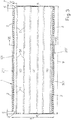
- the shelf 1 has a rectangular plan shape and it is obtained by subsequent operations shearing and bending sheet metal with a thickness S of about 0.7 mm ( fig. 8 ) and it has a depth A of about 504.5 mm and a width B of about 1328 mm.
- the rear side of the shelf 1 has a square bend 101 with a thickness of about 16.3 mm and it has a lower recessed part 201 with a corrugated profile, with a width D of about 25 mm.
- the front side of the shelf 1 has also the thickness C of about 16.3 mm, it has a bend 301 with a hook-like profile so that label holders or price holders can be snap fitted, it has a height E of about 13.8 mm and even this side ends by a lower and recessed bend 201' with a corrugated profile, similar to the rear one and having a width D' of about 25-26 mm.
- 201' rows of holes 2 are formed ( figs.2 , 3 , 6 , 7 ) corresponding holes 2' of the top face of the shelf 1 ( figs. 1 , 6 , 7 ) are aligned thereto and all these holes have a diameter of about 7 mm and are intended to receive small known guards, not shown, useful for confining the products displayed on the shelf 1 at the front and at the back.
- the rear side of the shelf 1 is smaller that the front one since the shelf at the rear corners is provided with recesses 3 having a width E of about 26 mm and a depth F of about 50 mm, useful for housing the uprights of the shelving.
- stiffeners 4 obtained by sheet metal with a thickness S' ( fig.8 ) of about 1 mm are fastened by a proper number of spot welds Z on their lips 104, spaced from each other by a distance decreasing towards the middle of the shelf 1 and arranged on lines parallel to the front and rear sides of the shelf 1. Good results have been achieved by providing two welds Z close to each other at each end of each lip 104 and by providing thirteen spot welds Z for each stiffener 4.
- the stiffeners 4 have an intermediate isosceles trapezoidal profile and have the lips 104 bent outwardly and coplanar with each other, and as a whole they have a profile that reminds of the inverted Omega letter of the Greek alphabet.
- the stiffeners 4 have a width G of the their smallest base 5 of about 71.4 mm, they are characterized by a distance between centers H of about 162 mm and the outer stiffeners are spaced from the front side of the shelf 1 by a distance L1 of about 50 mm and from the rear side of the same shelf 1 by a distance L2 of about 64.2 mm.
- the thickness M of the stiffeners 4 is about 17.3 mm that once it is summed to the thickness of the sheet metal forming the shelf 1 (0.7 mm) gives to the shelf 1 an overall thickness N of 18 mm.
- the shelf 1 is completed by fold-down lips 6 on the short sides, having rounded corners 106, having a height Q of 12 mm, which are spaced from the rear side and from the front side of the shelf 1 by a distance R1 of about 7 mm and by a distance R2 of about 50 mm respectively, which on the whole have an extension T of about 440 mm, which are spaced from the ends of the stiffeners 4 by a distance V of about 4.5 mm ( figs.
- brackets supporting the shelf 1 which are equipped on the top side with small slots also of known type for housing small lugs 8 of about 4 mm obtained by shearing and inwardly bending the lips 6.
- a shelf 1 By making a shelf 1 with the described characteristics, it is possible to guarantee a load capacity of about 180 kg and to arrange it with a front side as in figure 7 with a profile remarkably articulate such that it can support the same label holders or price holders that can be fit in the shelves of known type made with a metal wire.
- the shelves made with a metal wire are obtained combining in the superior part a circular metal wire with diameter of about 4 mm, in the inferior part a circular metal wire with diameter of about 8 mm, with interposed between them a mesh of transversal wire with diameter of about 2-3 mm, so that the frontal part has a total thickness of about 13,5-14 mm.
- the shelf 1 whose front side 301 is formed by a sheet metal profile, such that it superiorly has a superior coupling rib 12 and inferiorly an inferior coupling rib 13.
- the superior coupling rib 12 is constituted by a tooth-like profile, which is provided posteriorly with a recess.
- the inferior coupling rib 13 is constituted by a further tooth-like profile, which is provided posteriorly with a coupling wall.
- the front side 301 is suitable to couple with a label holding element with a C-like profile, being the two ends of the C-like profile suitable to couple respectively with the superior rib 12 and with the inferior rib 13.
- the C-like profile has preferably two radiuses of curvature which are different from each other.
- the said superior coupling rib 12 has a profile which can be comprised in an emicircle 120 with diameter of approximately 4 mm and the said inferior rib 13 has a profile which can be comprised in an emicircle 130 with diameter of approximately 8 mm.
- the front side 301 has a thickness of approximately 13,8 mm and with its shape can carry the same label holders or price holders mountable to the known shelves made with metal wire.
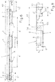
- the seventh upper shelf 1' is at a distance Y1 from the ground of about 1900-2000 mm, while in the shelving 10 on the right with the shelves 1 reduced to 18 mm, the seventh upper shelf 1 is at a distance Y2 from the ground of about 1700 mm, with the intuitable ergonomic advantages deriving therefrom.
Landscapes
- Assembled Shelves (AREA)
- Particle Accelerators (AREA)
Description
- The invention relates to metal shelving for displaying merchandise for sale, according to the preamble of
claim 1. - Document
US2010/0077781 discloses a metal shelving. - Also document
DE10306834 discloses a metal shelving Currently the thinnest sheet metal shelves produced by the applicant for the above mentioned shelving have a thickness of about 25 mm and with plan dimensions of about 50x133 cm they have a maximum load capacity of about 240 kg per shelf, e.g. as measured according to the technical regulations UNI 11262. Currently for example it is possible to arrange seven shelves with said thickness one on the other one, the first one being placed at about 10 cm from the ground, they are spaced from each other by about 25-27 cm, such to form a shelving whose last upper shelf is about 1900-2000 mm from the ground. This height is difficult to be reached by elder people and young people. - In addition to this there is the fact that merchandise to be displayed has often a reduced weight, such as for example breakfast products, jams, pasta and other ones that can be supported by shelves with a load capacity lower than the above mentioned one.
- In conventional shelving the shelves usually have a thickness equal to the distance between the slots of the upright.
- In this case, let p be the distance or pitch between the slots, it has to be noted that between two shelves spaced from each other heightwise by m pitches p, the space available heightwise for displaying the products is equal to (m*p-p), that is the space between two shelves spaced heightwise m*p is equal to m*p minus p, that is the thickness of a shelf itself.
- In conventional shelving, a product with a height Hi can be placed between two shelves spaced heightwise by m*p with

- The arrangement of all the shelves for receiving the products can cause the upper shelf to have an overall height from the ground that is too much for people of short stature.
- Therefore when manufacturing metal shelving the dimensioning of three contrasting magnitudes has to be faced, which have to be optimized in order to ideally meet the user needs: the display area of each shelf has to be wide enough, the overall height of the shelving has to be sufficiently reduced and contemporaneously it is necessary to guarantee a sufficient mechanical strength to the shelves, so to provide a good payload, and to the structure as a whole for supporting merchandise.
- The present invention aims at overcoming these drawbacks of currently known shelving and at optimizing the three magnitudes mentioned above, by providing a metal shelving for displaying merchandise, comprising at least two uprights to which a plurality of shelves is fastened, each upright being provided with slots for fastening the shelves, which slots are spaced from each other by a predetermined distance, wherein each shelf has a thickness lower than said predetermined distance between the slots.
- The present invention achieves the above aims with a metal shelving for displaying merchandise for sale according to
claim 1. - Thus the shelves have a thickness N lower than p and the space between two shelves spaced heightwise by m pitches p is greater, since the thickness of the shelf is reduced, and therefore the space is equal M*p-N.
- In a preferred example the shelves are rested on adjustable brackets, fastened to the uprights by means of the slots for the insertion of brackets at pitch p= 25 mm.
- Therefore the shelving is such that it makes it possible to place the shelves at a height from the ground lower than the corresponding case wherein the shelves have a thickness coinciding with the pitch of the slots p.
- It is the interest of the exhibitor to maintain the level of the upper shelves as low as possible, such to allow the users, even not tall ones, to willingly buy the products displayed on the upper shelves. For this reason usually the arrangement of the shelves is designed such to guarantee a level of the uppermost shelf sufficiently reachable by the users. The workers of the store have to select the lowest level where the brackets are inserted in the upright, such to place the shelves for properly displaying merchandise and to allow the smallest overall height of the shelving.
- Therefore the shelving of the new type is able to arrange under the shelf the products having a height Hi ranging


- The new type of shelving allows therefore to allocate the products having a height Hj even between two shelves m*p apart from each other, which on the contrary in the state of the art would require to be placed between two shelves with a distance in height from each other of (m+1)*p (in other words, with a height increased of one pace p more with respect to m*p). Thus the shelving is able to earn one pace p in height for all those products which have a height with the features of Hj.
- Therefore the shelving offers an increased versatility in mounting the products, because it allows to place between two shelves m*p apart from each other, all those products of height Hk such that


- From all the above it appears clearly that every time it is possible to place the products between two shelves spaced heightwise by m*p with a height Hi and also those with a height Hj, then it is possible to gain a pitch to the bottom for positioning the shelves and the brackets.
- Since in a store there are many displayed products, according to the law of large numbers, the number of cases when it is possible to reduce by a pitch p the positioning heightwise between adjacent shelves is considerable, and this makes it possible to gain several pitches p to the bottom on one upright.
- For example in the case of a shelving with 8 shelves, if it is possible for 50% of the cases to lower by a pitch p the height of the bracket supporting the shelf, then on average the height of the uppermost shelf is reduced by 8 shelves * 50% * p = 8*0.5*25 mm = 100 mm, which denotes the gain in height of the shelving, with respect to conventional shelving. According to the invention, the top shelf has a distance from the ground ranging from 1500 to 1900 mm, preferably ranging from 1600 mm to 1800 mm.
- The lower shelf has a distance from the ground ranging from 110 mm to 160 mm.
- In one preferred embodiment there are provided seven shelves, but it is possible to provide also six or eight shelves or similar numbers. According to the invention, the shelf has a thickness lower than 20 mm, preferably of about 18 mm, and it is obtained from a sheet metal with a thickness of 0.7 mm, by means of subsequent shearing and bending operations.
- The shelves have the same plan dimensions as the conventional shelves and are reinforced such to have a load capacity per shelf slightly less than 200 kg.
- With these shelves having a reduced thickness, it is possible to make shelving with the same number of shelves as those with a thickness of 25 mm, as in the above example, spaced from each other by an equal or slightly lower distance, wherein the seventh upper shelf has a distance from the ground of about 1800 mm, unlike the previous about 2000 mm, with the intuitable advantages deriving from this condition. According to the invention, each shelf has a payload greater than 100 Kg, preferably comprised between 160 and 200 Kg, in particular corresponding to 180 Kg. According to the invetion, the front side of the shelf and the rear one are ribbed and profiled by downward and inward bends, and the shelf at the ends is equipped with down-fold lips that are side by side to supporting brackets. The supporting brackets are obtained from a metal plate and are hooked in a projecting manner to the upright of the shelving. The ends of the sheet metal forming said shelf rest on the brackets. Said profiled parts of the front side and of the rear side of the same shelf, as well as the ends of metal stiffeners with an inverted omega profile, also obtained by shearing and bending sheet metal, parallel to said front and rear ribbed sides and that with their lips are fastened on the lower face of the same shelf by means of spot welds rest on such brackets.
- The stiffeners are obtained from a sheet metal with a thickness of 1 mm.
- Further characteristics of the invention and the advantages deriving therefrom will be more clear from the following description made with reference to the figures of the four annexed drawing tables, wherein:
-
Figs.1 and 2 are partial and perspective views, from the top and from the bottom and observing at one end, of a portion of the shelf of interest; -
Fig.3 is the plan view from the bottom; -
Figs. 4 and 5 are front views of the front and rear sides respectively of the shelf of interest; -
Fig.6 is the details according to the cross-sectional line VI-VI offigure 3 ; -
Figs. 7 and8 are side and enlarged views of the parts with the front side and the part with the rear side of the shelf offigure 6 , denoted by K1 and K2 respectively; -
Fig.9 is a front view of a double metal shelving with on the left of the same upright the known shelves with a thickness of 25 mm hooked thereto and on the right of the upright it has the shelves with the thickness reduced to 18 mm. - From
figures 1, 2 and3 it is clear that theshelf 1 according to the invention has a rectangular plan shape and it is obtained by subsequent operations shearing and bending sheet metal with a thickness S of about 0.7 mm (fig. 8 ) and it has a depth A of about 504.5 mm and a width B of about 1328 mm. With reference also tofigures 5 ,6 and7 it is noted that the rear side of theshelf 1 has asquare bend 101 with a thickness of about 16.3 mm and it has a lowerrecessed part 201 with a corrugated profile, with a width D of about 25 mm. The front side of theshelf 1 has also the thickness C of about 16.3 mm, it has abend 301 with a hook-like profile so that label holders or price holders can be snap fitted, it has a height E of about 13.8 mm and even this side ends by a lower and recessed bend 201' with a corrugated profile, similar to the rear one and having a width D' of about 25-26 mm. On the intermediate portion of said lower andcorrugated profiles 201, 201' rows ofholes 2 are formed (figs.2 ,3 ,6 ,7 ) corresponding holes 2' of the top face of the shelf 1 (figs. 1 ,6 ,7 ) are aligned thereto and all these holes have a diameter of about 7 mm and are intended to receive small known guards, not shown, useful for confining the products displayed on theshelf 1 at the front and at the back. - From
figures 1 to 3 it is noted that the rear side of theshelf 1 is smaller that the front one since the shelf at the rear corners is provided withrecesses 3 having a width E of about 26 mm and a depth F of about 50 mm, useful for housing the uprights of the shelving. - On the lower face of the
shelf 1 threestiffeners 4 obtained by sheet metal with a thickness S' (fig.8 ) of about 1 mm are fastened by a proper number of spot welds Z on theirlips 104, spaced from each other by a distance decreasing towards the middle of theshelf 1 and arranged on lines parallel to the front and rear sides of theshelf 1. Good results have been achieved by providing two welds Z close to each other at each end of eachlip 104 and by providing thirteen spot welds Z for eachstiffener 4. Thestiffeners 4 have an intermediate isosceles trapezoidal profile and have thelips 104 bent outwardly and coplanar with each other, and as a whole they have a profile that reminds of the inverted Omega letter of the Greek alphabet. Thestiffeners 4 have a width G of the their smallest base 5 of about 71.4 mm, they are characterized by a distance between centers H of about 162 mm and the outer stiffeners are spaced from the front side of theshelf 1 by a distance L1 of about 50 mm and from the rear side of thesame shelf 1 by a distance L2 of about 64.2 mm. - The thickness M of the
stiffeners 4 is about 17.3 mm that once it is summed to the thickness of the sheet metal forming the shelf 1 (0.7 mm) gives to theshelf 1 an overall thickness N of 18 mm. - The
shelf 1 is completed by fold-downlips 6 on the short sides, havingrounded corners 106, having a height Q of 12 mm, which are spaced from the rear side and from the front side of theshelf 1 by a distance R1 of about 7 mm and by a distance R2 of about 50 mm respectively, which on the whole have an extension T of about 440 mm, which are spaced from the ends of thestiffeners 4 by a distance V of about 4.5 mm (figs. 4, 5 ) and at the ends they are provided withholes 7 with a diameter of 5 mm, wherein known appendages of said brackets supporting theshelf 1 can be inserted which are equipped on the top side with small slots also of known type for housingsmall lugs 8 of about 4 mm obtained by shearing and inwardly bending thelips 6. - By making a
shelf 1 with the described characteristics, it is possible to guarantee a load capacity of about 180 kg and to arrange it with a front side as infigure 7 with a profile remarkably articulate such that it can support the same label holders or price holders that can be fit in the shelves of known type made with a metal wire. In the state of the art, it is known that the shelves made with a metal wire are obtained combining in the superior part a circular metal wire with diameter of about 4 mm, in the inferior part a circular metal wire with diameter of about 8 mm, with interposed between them a mesh of transversal wire with diameter of about 2-3 mm, so that the frontal part has a total thickness of about 13,5-14 mm. - In the embodiment of
figure 7 , it can be seen theshelf 1, whosefront side 301 is formed by a sheet metal profile, such that it superiorly has asuperior coupling rib 12 and inferiorly aninferior coupling rib 13. - The
superior coupling rib 12 is constituted by a tooth-like profile, which is provided posteriorly with a recess. - The
inferior coupling rib 13 is constituted by a further tooth-like profile, which is provided posteriorly with a coupling wall. - In this way, the
front side 301 is suitable to couple with a label holding element with a C-like profile, being the two ends of the C-like profile suitable to couple respectively with thesuperior rib 12 and with theinferior rib 13. - In an embodiment the C-like profile has preferably two radiuses of curvature which are different from each other.
- The said
superior coupling rib 12 has a profile which can be comprised in anemicircle 120 with diameter of approximately 4 mm and the saidinferior rib 13 has a profile which can be comprised in anemicircle 130 with diameter of approximately 8 mm. - The
front side 301 has a thickness of approximately 13,8 mm and with its shape can carry the same label holders or price holders mountable to the known shelves made with metal wire. - By means of metal shelves with a thickness of 18 mm as in the present invention, it is possible also to achieve the advantages of the non limitative example of
figure 9 , where 10' shows conventional metal shelving using shelves 1' with the known thickness of 25 mm, spaced from each other by about 25 mm and hooked by their supporting brackets 11' to the left of an upright 9 with an height Y of about 2000-2100 mm, at the right thereofshelves 1 according to the invention with a thickness of 18 mm are hooked by theirbrackets 11, such to form asecond shelving 10 whoseshelves 1 are spaced from each other such to easily support, both for the insertion and for the removal, the same products X with an height of about 23-24 cm which are supported with a higher vertical allowance in the known shelving 10'. In the known shelving 10' the seventh upper shelf 1' is at a distance Y1 from the ground of about 1900-2000 mm, while in theshelving 10 on the right with theshelves 1 reduced to 18 mm, the seventhupper shelf 1 is at a distance Y2 from the ground of about 1700 mm, with the intuitable ergonomic advantages deriving therefrom. - It is clear that all the technical equivalents and the proportional dimensioning deducible from what disclosed and described herein fall within the scope of the invention, therefore the scope of protection of the invention has to be intended as covering all those shelf designs with plan dimensions different than the example considered herein, which will be proportionally dimensioned such to achieve the same utility, by using the same innovative concept, all this without departing from the teaching principle of the present invention as described, shown and claimed below. In the claims, the references in the brackets are merely as an indication and not a limitation of the scope of protection of the claims themselves.
Claims (8)
- Metal shelving for displaying merchandise, comprising at least two uprights (9) to which a plurality of shelves (1) is fastened, each upright (9) being provided with slots for fastening the shelves (1), which slots are arranged at a predetermined distance from each other, wherein each shelf (1) has a thickness (N) lower than said predetermined distance between the slots;.
the upper shelf has a distance from the ground ranging from 1500 mm to 1900 mm, preferably ranging from 1600 mm to 1800 mm;
the lower shelf has a distance from the ground ranging from 110 mm to 160 mm, preferably ranging from 150 mm to 180 mm;
the shelf (1) has a thickness (N) lower than 20 mm;
each shelf (1) has a payload greater than 100 Kg, preferably comprised between 160 and 200 Kg, in particular corresponding to 180 Kg;
each shelf (1) obtained from a sheet metal by subsequent shearing and bending operations, whose front side (301, 201') and rear one (101, 201) are ribbed and profiled with downward and inward bends, at the ends it is provided with down-fold lips (6) which are side by side to supporting brackets (11) obtained from a metal plate and are hooked in a projecting manner to the upright (9) of the shelving, the ends of the sheet metal forming said shelf (1) rest on such brackets and said profiled parts of the front side and of the rear side of the same shelf (1), as well as the ends of metal stiffeners (4) with an inverted omega profile, obtained also by means of shearing and bending operations from sheet metal, parallel to said front and rear ribbed sides of the shelf (1) and that with their lips are fastened on the lower face of the same shelf (1) by means of spot welds (Z) rest on such brackets;
and wherein each lip of the stiffeners (4) is provided with a central spot weld (Z) located at half its longitudinal extension, the said lips being further provided with an arrangement of two first sets of four spot welds, the first sets being symmetrically arranged with respect to the central spot weld and wherein the spot welds of each first set are spaced from each other by a distance, decreasing towards the middle of the shelf, each lip being further provided with a second set of two spot welds provided at each end of each lip, the said second sets being symmetrically arranged with respect to the central spot and wherein the spot welds of each second sets are spaced from each other by a distance smaller than the distance between the spot welds of the first two sets. - Shelving according to claim 1, wherein there are provided seven shelves.
- Shelving according to claim 1, wherein said thickness (N) of the shelf is about of 18 mm.
- Shelving according to one or more of the prceding claims , wherein the front side (301) is formed by a sheet metal profile, such that it superiorly has a superior coupling rib (12), constituted by a tooth-like profile which is provided posteriorly with a recess, and inferiorly an inferior coupling rib (13) constituted by a further tooth-like profile which is provided posteriorly with a coupling wall, such that the front side (301) is suitable to couple with a label holding element with a C-like profile.
- Shelving according to claim 4, wherein the said superior coupling rib (12) has a profile which can be comprised in an emicircle (120) with diameter of approximately 4 mm, the said inferior rib (13) has a profile which can be comprised in an emicircle (130) with diameter of approximately 8 mm, and the front side (301) has a bend with thickness of approximately 13,8 mm.
- Shelving according to one or more of the precedeing claims, wherein the shelf (1) is obtained from sheet metal with a thickness of 0.7 mm, while said stiffeners (4) are obtained from sheet metal with a thickness of 1 mm.
- Shelving according to one or more of the preceding claims, wherein the shelf (1) has a width (B) and a depth (A) of about 1300 mm and about 504.5 mm respectively, characterized by using three of said stiffeners (4) with a isosceles trapezoidal median profile, with the smallest base having a width (G) ranging from 70 to 72 mm, for example of about 71.4 mm, as well as a distance between centers (H) ranging from 160 to 165 mm for example of about 162 mm and by the fact that such stiffener (4) is spaced from the front side of the shelf (1) by a distance (L1) of about 50 mm, while the opposite stiffener (4) is spaced from the rear side of the shelf (1) by a distance (L2) ranging from 60 to 65 mm, for example about of 64.2 mm.
- Shelving according to one or more of the preceding claims, wherein the thickness (C) of the rear ribbed and bent sides of the shelf (1) ranges from 16 to 16.5 mm and for example it is of about 16.3 mm.
Priority Applications (3)
| Application Number | Priority Date | Filing Date | Title |
|---|---|---|---|
| PL14736706T PL2863775T3 (en) | 2013-07-04 | 2014-06-30 | Metal shelving for displaying merchandise |
| EP17176817.9A EP3241465B1 (en) | 2013-07-04 | 2014-06-30 | Metal shelving with reduced thickness for displaying merchandise |
| PL17176817T PL3241465T3 (en) | 2013-07-04 | 2014-06-30 | Metal shelving with reduced thickness for displaying merchandise |
Applications Claiming Priority (2)
| Application Number | Priority Date | Filing Date | Title |
|---|---|---|---|
| IT000077U ITBO20130077U1 (en) | 2013-07-04 | 2013-07-04 | LOW THICKNESS PLAN FOR METAL SHELVES FOR THE EXPOSURE OF GOODS |
| PCT/EP2014/063860 WO2015000852A1 (en) | 2013-07-04 | 2014-06-30 | Metal shelving for displaying merchandise |
Related Child Applications (2)
| Application Number | Title | Priority Date | Filing Date |
|---|---|---|---|
| EP17176817.9A Division EP3241465B1 (en) | 2013-07-04 | 2014-06-30 | Metal shelving with reduced thickness for displaying merchandise |
| EP17176817.9A Division-Into EP3241465B1 (en) | 2013-07-04 | 2014-06-30 | Metal shelving with reduced thickness for displaying merchandise |
Publications (2)
| Publication Number | Publication Date |
|---|---|
| EP2863775A1 EP2863775A1 (en) | 2015-04-29 |
| EP2863775B1 true EP2863775B1 (en) | 2017-08-02 |
Family
ID=50678373
Family Applications (2)
| Application Number | Title | Priority Date | Filing Date |
|---|---|---|---|
| EP17176817.9A Active EP3241465B1 (en) | 2013-07-04 | 2014-06-30 | Metal shelving with reduced thickness for displaying merchandise |
| EP14736706.4A Active EP2863775B1 (en) | 2013-07-04 | 2014-06-30 | Metal shelving for displaying merchandise |
Family Applications Before (1)
| Application Number | Title | Priority Date | Filing Date |
|---|---|---|---|
| EP17176817.9A Active EP3241465B1 (en) | 2013-07-04 | 2014-06-30 | Metal shelving with reduced thickness for displaying merchandise |
Country Status (5)
| Country | Link |
|---|---|
| EP (2) | EP3241465B1 (en) |
| ES (2) | ES2886930T3 (en) |
| IT (1) | ITBO20130077U1 (en) |
| PL (2) | PL3241465T3 (en) |
| WO (1) | WO2015000852A1 (en) |
Cited By (1)
| Publication number | Priority date | Publication date | Assignee | Title |
|---|---|---|---|---|
| RU192291U1 (en) * | 2019-07-19 | 2019-09-11 | Общество с ограниченной ответственностью "Борский завод торгового оборудования" | Metal shelving |
Families Citing this family (3)
| Publication number | Priority date | Publication date | Assignee | Title |
|---|---|---|---|---|
| IT201700035477A1 (en) | 2017-03-31 | 2018-10-01 | Cefla Soc Cooperativa | REINFORCED FLOORING OF METAL SHELVES PROVIDED WITH OPENINGS FOR THE PASSAGE AND SUPPORT OF ELECTRIC CABLES, WITH EASY INSTALLATION |
| JP7189140B2 (en) | 2017-08-03 | 2022-12-13 | 武田薬品工業株式会社 | Heterocyclic compounds and uses thereof |
| US12091410B2 (en) | 2018-12-12 | 2024-09-17 | Takeda Pharmaceutical Company Limited | Heterocyclic compound |
Family Cites Families (6)
| Publication number | Priority date | Publication date | Assignee | Title |
|---|---|---|---|---|
| US2005593A (en) * | 1933-07-11 | 1935-06-18 | Luxe Metal Furniture Company D | Shelving |
| US2845187A (en) * | 1955-01-19 | 1958-07-29 | Proctor & Schwartz Inc | Shelf assembly |
| US4098480A (en) * | 1976-10-26 | 1978-07-04 | Lozier Store Fixtures | Universal shelf system |
| DE29702781U1 (en) * | 1997-02-18 | 1997-04-03 | König Ladenbau-Innenausbau GmbH & Co. KG, 46238 Bottrop | shelf |
| DE10306834B3 (en) * | 2003-02-18 | 2004-04-01 | Lüning Ladenbau GmbH | Fixing system for presenting goods comprises columns with fixing openings and bars arranged between them, and a console pair with bearing surfaces arranged at a distance above a hook-like fixing element |
| EP1887914A4 (en) | 2005-05-26 | 2009-12-02 | Carrier Corp | Refrigerator case shelf |
-
2013
- 2013-07-04 IT IT000077U patent/ITBO20130077U1/en unknown
-
2014
- 2014-06-30 WO PCT/EP2014/063860 patent/WO2015000852A1/en not_active Ceased
- 2014-06-30 ES ES17176817T patent/ES2886930T3/en active Active
- 2014-06-30 ES ES14736706.4T patent/ES2641730T3/en active Active
- 2014-06-30 PL PL17176817T patent/PL3241465T3/en unknown
- 2014-06-30 PL PL14736706T patent/PL2863775T3/en unknown
- 2014-06-30 EP EP17176817.9A patent/EP3241465B1/en active Active
- 2014-06-30 EP EP14736706.4A patent/EP2863775B1/en active Active
Non-Patent Citations (1)
| Title |
|---|
| None * |
Cited By (1)
| Publication number | Priority date | Publication date | Assignee | Title |
|---|---|---|---|---|
| RU192291U1 (en) * | 2019-07-19 | 2019-09-11 | Общество с ограниченной ответственностью "Борский завод торгового оборудования" | Metal shelving |
Also Published As
| Publication number | Publication date |
|---|---|
| ES2641730T3 (en) | 2017-11-13 |
| PL2863775T3 (en) | 2018-01-31 |
| EP3241465B1 (en) | 2021-08-04 |
| ES2886930T3 (en) | 2021-12-21 |
| EP3241465A1 (en) | 2017-11-08 |
| PL3241465T3 (en) | 2021-11-22 |
| ITBO20130077U1 (en) | 2015-01-05 |
| EP2863775A1 (en) | 2015-04-29 |
| WO2015000852A1 (en) | 2015-01-08 |
Similar Documents
| Publication | Publication Date | Title |
|---|---|---|
| US6044989A (en) | Display rack with interlocking divider and divider array systems | |
| US9016484B2 (en) | Display tray and bar, and mounting bracket therefor | |
| US4705178A (en) | Wire cube for use in a modular display rack | |
| US8210367B2 (en) | Width-adjustable product display tray with novel mounting arrangement | |
| EP3241465B1 (en) | Metal shelving with reduced thickness for displaying merchandise | |
| US4501369A (en) | Merchandise display means | |
| US7048131B2 (en) | Open frame shelf assembly | |
| US4079678A (en) | Shelving system | |
| AU622954B2 (en) | A display system | |
| US5947307A (en) | Self standing merchandiser | |
| US8967576B2 (en) | Assembly for a storage unit | |
| US9867483B2 (en) | Signage systems and merchandising display assemblies | |
| EP1996049B1 (en) | A blank for a rack | |
| US10681977B2 (en) | Shelving post and an adjustable shelving system | |
| CN103284523A (en) | System for displaying products on a shelf | |
| US6006926A (en) | Display shelving | |
| US5022540A (en) | Stackable wire cubes for use in a modular display rack | |
| US10660433B1 (en) | Modular shelf assembly | |
| US6837387B2 (en) | Modular product display | |
| CA2868584A1 (en) | Merchandise display system | |
| US9622595B2 (en) | Modular display rack with header with a contoured surface | |
| US4706820A (en) | Gravity feed shelf for store gondolas | |
| US3225719A (en) | Display and storage shelving | |
| JP6799809B2 (en) | Frame members, shelves and showcases | |
| RU81416U1 (en) | COMPACT ASSEMBLY RACK |
Legal Events
| Date | Code | Title | Description |
|---|---|---|---|
| PUAI | Public reference made under article 153(3) epc to a published international application that has entered the european phase |
Free format text: ORIGINAL CODE: 0009012 |
|
| 17P | Request for examination filed |
Effective date: 20150126 |
|
| AK | Designated contracting states |
Kind code of ref document: A1 Designated state(s): AL AT BE BG CH CY CZ DE DK EE ES FI FR GB GR HR HU IE IS IT LI LT LU LV MC MK MT NL NO PL PT RO RS SE SI SK SM TR |
|
| AX | Request for extension of the european patent |
Extension state: BA ME |
|
| 17Q | First examination report despatched |
Effective date: 20150727 |
|
| DAX | Request for extension of the european patent (deleted) | ||
| STAA | Information on the status of an ep patent application or granted ep patent |
Free format text: STATUS: EXAMINATION IS IN PROGRESS |
|
| GRAP | Despatch of communication of intention to grant a patent |
Free format text: ORIGINAL CODE: EPIDOSNIGR1 |
|
| STAA | Information on the status of an ep patent application or granted ep patent |
Free format text: STATUS: GRANT OF PATENT IS INTENDED |
|
| INTG | Intention to grant announced |
Effective date: 20170220 |
|
| GRAS | Grant fee paid |
Free format text: ORIGINAL CODE: EPIDOSNIGR3 |
|
| GRAA | (expected) grant |
Free format text: ORIGINAL CODE: 0009210 |
|
| STAA | Information on the status of an ep patent application or granted ep patent |
Free format text: STATUS: THE PATENT HAS BEEN GRANTED |
|
| AK | Designated contracting states |
Kind code of ref document: B1 Designated state(s): AL AT BE BG CH CY CZ DE DK EE ES FI FR GB GR HR HU IE IS IT LI LT LU LV MC MK MT NL NO PL PT RO RS SE SI SK SM TR |
|
| REG | Reference to a national code |
Ref country code: CH Ref legal event code: EP Ref country code: AT Ref legal event code: REF Ref document number: 913503 Country of ref document: AT Kind code of ref document: T Effective date: 20170815 |
|
| REG | Reference to a national code |
Ref country code: IE Ref legal event code: FG4D |
|
| REG | Reference to a national code |
Ref country code: DE Ref legal event code: R096 Ref document number: 602014012595 Country of ref document: DE |
|
| REG | Reference to a national code |
Ref country code: ES Ref legal event code: FG2A Ref document number: 2641730 Country of ref document: ES Kind code of ref document: T3 Effective date: 20171113 |
|
| REG | Reference to a national code |
Ref country code: NL Ref legal event code: MP Effective date: 20170802 |
|
| REG | Reference to a national code |
Ref country code: AT Ref legal event code: MK05 Ref document number: 913503 Country of ref document: AT Kind code of ref document: T Effective date: 20170802 |
|
| REG | Reference to a national code |
Ref country code: LT Ref legal event code: MG4D |
|
| PG25 | Lapsed in a contracting state [announced via postgrant information from national office to epo] |
Ref country code: NL Free format text: LAPSE BECAUSE OF FAILURE TO SUBMIT A TRANSLATION OF THE DESCRIPTION OR TO PAY THE FEE WITHIN THE PRESCRIBED TIME-LIMIT Effective date: 20170802 Ref country code: LT Free format text: LAPSE BECAUSE OF FAILURE TO SUBMIT A TRANSLATION OF THE DESCRIPTION OR TO PAY THE FEE WITHIN THE PRESCRIBED TIME-LIMIT Effective date: 20170802 Ref country code: FI Free format text: LAPSE BECAUSE OF FAILURE TO SUBMIT A TRANSLATION OF THE DESCRIPTION OR TO PAY THE FEE WITHIN THE PRESCRIBED TIME-LIMIT Effective date: 20170802 Ref country code: NO Free format text: LAPSE BECAUSE OF FAILURE TO SUBMIT A TRANSLATION OF THE DESCRIPTION OR TO PAY THE FEE WITHIN THE PRESCRIBED TIME-LIMIT Effective date: 20171102 Ref country code: SE Free format text: LAPSE BECAUSE OF FAILURE TO SUBMIT A TRANSLATION OF THE DESCRIPTION OR TO PAY THE FEE WITHIN THE PRESCRIBED TIME-LIMIT Effective date: 20170802 Ref country code: HR Free format text: LAPSE BECAUSE OF FAILURE TO SUBMIT A TRANSLATION OF THE DESCRIPTION OR TO PAY THE FEE WITHIN THE PRESCRIBED TIME-LIMIT Effective date: 20170802 Ref country code: AT Free format text: LAPSE BECAUSE OF FAILURE TO SUBMIT A TRANSLATION OF THE DESCRIPTION OR TO PAY THE FEE WITHIN THE PRESCRIBED TIME-LIMIT Effective date: 20170802 |
|
| PG25 | Lapsed in a contracting state [announced via postgrant information from national office to epo] |
Ref country code: LV Free format text: LAPSE BECAUSE OF FAILURE TO SUBMIT A TRANSLATION OF THE DESCRIPTION OR TO PAY THE FEE WITHIN THE PRESCRIBED TIME-LIMIT Effective date: 20170802 Ref country code: RS Free format text: LAPSE BECAUSE OF FAILURE TO SUBMIT A TRANSLATION OF THE DESCRIPTION OR TO PAY THE FEE WITHIN THE PRESCRIBED TIME-LIMIT Effective date: 20170802 Ref country code: IS Free format text: LAPSE BECAUSE OF FAILURE TO SUBMIT A TRANSLATION OF THE DESCRIPTION OR TO PAY THE FEE WITHIN THE PRESCRIBED TIME-LIMIT Effective date: 20171202 Ref country code: BG Free format text: LAPSE BECAUSE OF FAILURE TO SUBMIT A TRANSLATION OF THE DESCRIPTION OR TO PAY THE FEE WITHIN THE PRESCRIBED TIME-LIMIT Effective date: 20171102 Ref country code: GR Free format text: LAPSE BECAUSE OF FAILURE TO SUBMIT A TRANSLATION OF THE DESCRIPTION OR TO PAY THE FEE WITHIN THE PRESCRIBED TIME-LIMIT Effective date: 20171103 |
|
| PG25 | Lapsed in a contracting state [announced via postgrant information from national office to epo] |
Ref country code: DK Free format text: LAPSE BECAUSE OF FAILURE TO SUBMIT A TRANSLATION OF THE DESCRIPTION OR TO PAY THE FEE WITHIN THE PRESCRIBED TIME-LIMIT Effective date: 20170802 Ref country code: CZ Free format text: LAPSE BECAUSE OF FAILURE TO SUBMIT A TRANSLATION OF THE DESCRIPTION OR TO PAY THE FEE WITHIN THE PRESCRIBED TIME-LIMIT Effective date: 20170802 Ref country code: RO Free format text: LAPSE BECAUSE OF FAILURE TO SUBMIT A TRANSLATION OF THE DESCRIPTION OR TO PAY THE FEE WITHIN THE PRESCRIBED TIME-LIMIT Effective date: 20170802 |
|
| REG | Reference to a national code |
Ref country code: DE Ref legal event code: R097 Ref document number: 602014012595 Country of ref document: DE |
|
| PG25 | Lapsed in a contracting state [announced via postgrant information from national office to epo] |
Ref country code: SK Free format text: LAPSE BECAUSE OF FAILURE TO SUBMIT A TRANSLATION OF THE DESCRIPTION OR TO PAY THE FEE WITHIN THE PRESCRIBED TIME-LIMIT Effective date: 20170802 Ref country code: EE Free format text: LAPSE BECAUSE OF FAILURE TO SUBMIT A TRANSLATION OF THE DESCRIPTION OR TO PAY THE FEE WITHIN THE PRESCRIBED TIME-LIMIT Effective date: 20170802 Ref country code: SM Free format text: LAPSE BECAUSE OF FAILURE TO SUBMIT A TRANSLATION OF THE DESCRIPTION OR TO PAY THE FEE WITHIN THE PRESCRIBED TIME-LIMIT Effective date: 20170802 |
|
| REG | Reference to a national code |
Ref country code: FR Ref legal event code: PLFP Year of fee payment: 5 |
|
| PLBE | No opposition filed within time limit |
Free format text: ORIGINAL CODE: 0009261 |
|
| STAA | Information on the status of an ep patent application or granted ep patent |
Free format text: STATUS: NO OPPOSITION FILED WITHIN TIME LIMIT |
|
| 26N | No opposition filed |
Effective date: 20180503 |
|
| PG25 | Lapsed in a contracting state [announced via postgrant information from national office to epo] |
Ref country code: SI Free format text: LAPSE BECAUSE OF FAILURE TO SUBMIT A TRANSLATION OF THE DESCRIPTION OR TO PAY THE FEE WITHIN THE PRESCRIBED TIME-LIMIT Effective date: 20170802 |
|
| REG | Reference to a national code |
Ref country code: CH Ref legal event code: PL |
|
| GBPC | Gb: european patent ceased through non-payment of renewal fee |
Effective date: 20180630 |
|
| REG | Reference to a national code |
Ref country code: BE Ref legal event code: MM Effective date: 20180630 |
|
| PG25 | Lapsed in a contracting state [announced via postgrant information from national office to epo] |
Ref country code: LU Free format text: LAPSE BECAUSE OF NON-PAYMENT OF DUE FEES Effective date: 20180630 Ref country code: MC Free format text: LAPSE BECAUSE OF FAILURE TO SUBMIT A TRANSLATION OF THE DESCRIPTION OR TO PAY THE FEE WITHIN THE PRESCRIBED TIME-LIMIT Effective date: 20170802 |
|
| REG | Reference to a national code |
Ref country code: IE Ref legal event code: MM4A |
|
| PG25 | Lapsed in a contracting state [announced via postgrant information from national office to epo] |
Ref country code: IE Free format text: LAPSE BECAUSE OF NON-PAYMENT OF DUE FEES Effective date: 20180630 Ref country code: GB Free format text: LAPSE BECAUSE OF NON-PAYMENT OF DUE FEES Effective date: 20180630 Ref country code: CH Free format text: LAPSE BECAUSE OF NON-PAYMENT OF DUE FEES Effective date: 20180630 Ref country code: LI Free format text: LAPSE BECAUSE OF NON-PAYMENT OF DUE FEES Effective date: 20180630 |
|
| PG25 | Lapsed in a contracting state [announced via postgrant information from national office to epo] |
Ref country code: BE Free format text: LAPSE BECAUSE OF NON-PAYMENT OF DUE FEES Effective date: 20180630 |
|
| PG25 | Lapsed in a contracting state [announced via postgrant information from national office to epo] |
Ref country code: MT Free format text: LAPSE BECAUSE OF NON-PAYMENT OF DUE FEES Effective date: 20180630 |
|
| PG25 | Lapsed in a contracting state [announced via postgrant information from national office to epo] |
Ref country code: PT Free format text: LAPSE BECAUSE OF FAILURE TO SUBMIT A TRANSLATION OF THE DESCRIPTION OR TO PAY THE FEE WITHIN THE PRESCRIBED TIME-LIMIT Effective date: 20170802 |
|
| PG25 | Lapsed in a contracting state [announced via postgrant information from national office to epo] |
Ref country code: HU Free format text: LAPSE BECAUSE OF FAILURE TO SUBMIT A TRANSLATION OF THE DESCRIPTION OR TO PAY THE FEE WITHIN THE PRESCRIBED TIME-LIMIT; INVALID AB INITIO Effective date: 20140630 Ref country code: CY Free format text: LAPSE BECAUSE OF FAILURE TO SUBMIT A TRANSLATION OF THE DESCRIPTION OR TO PAY THE FEE WITHIN THE PRESCRIBED TIME-LIMIT Effective date: 20170802 Ref country code: MK Free format text: LAPSE BECAUSE OF NON-PAYMENT OF DUE FEES Effective date: 20170802 |
|
| PG25 | Lapsed in a contracting state [announced via postgrant information from national office to epo] |
Ref country code: AL Free format text: LAPSE BECAUSE OF FAILURE TO SUBMIT A TRANSLATION OF THE DESCRIPTION OR TO PAY THE FEE WITHIN THE PRESCRIBED TIME-LIMIT Effective date: 20170802 |
|
| REG | Reference to a national code |
Ref country code: DE Ref legal event code: R081 Ref document number: 602014012595 Country of ref document: DE Owner name: IMOLA RETAIL SOLUTIONS S.R.L., IMOLA, IT Free format text: FORMER OWNER: CEFLA SOCIETA COOPERATIVA, IMOLA, BOLOGNA, IT |
|
| REG | Reference to a national code |
Ref country code: ES Ref legal event code: PC2A Owner name: IMOLA RETAIL SOLUTIONS S.R.L. Effective date: 20210608 |
|
| PGFP | Annual fee paid to national office [announced via postgrant information from national office to epo] |
Ref country code: DE Payment date: 20250618 Year of fee payment: 12 Ref country code: PL Payment date: 20250624 Year of fee payment: 12 |
|
| PGFP | Annual fee paid to national office [announced via postgrant information from national office to epo] |
Ref country code: IT Payment date: 20250424 Year of fee payment: 12 |
|
| PGFP | Annual fee paid to national office [announced via postgrant information from national office to epo] |
Ref country code: FR Payment date: 20250625 Year of fee payment: 12 |
|
| PGFP | Annual fee paid to national office [announced via postgrant information from national office to epo] |
Ref country code: TR Payment date: 20250624 Year of fee payment: 12 |
|
| PGFP | Annual fee paid to national office [announced via postgrant information from national office to epo] |
Ref country code: ES Payment date: 20250728 Year of fee payment: 12 |