EP2863574A1 - Ack/nack feedback bit number determination method and device - Google Patents
Ack/nack feedback bit number determination method and device Download PDFInfo
- Publication number
- EP2863574A1 EP2863574A1 EP13806080.1A EP13806080A EP2863574A1 EP 2863574 A1 EP2863574 A1 EP 2863574A1 EP 13806080 A EP13806080 A EP 13806080A EP 2863574 A1 EP2863574 A1 EP 2863574A1
- Authority
- EP
- European Patent Office
- Prior art keywords
- carrier
- sub
- frames
- dai
- frame
- Prior art date
- Legal status (The legal status is an assumption and is not a legal conclusion. Google has not performed a legal analysis and makes no representation as to the accuracy of the status listed.)
- Granted
Links
Images


Classifications
-
- H—ELECTRICITY
- H04—ELECTRIC COMMUNICATION TECHNIQUE
- H04L—TRANSMISSION OF DIGITAL INFORMATION, e.g. TELEGRAPHIC COMMUNICATION
- H04L5/00—Arrangements affording multiple use of the transmission path
- H04L5/003—Arrangements for allocating sub-channels of the transmission path
- H04L5/0053—Allocation of signalling, i.e. of overhead other than pilot signals
- H04L5/0055—Physical resource allocation for ACK/NACK
-
- H—ELECTRICITY
- H04—ELECTRIC COMMUNICATION TECHNIQUE
- H04L—TRANSMISSION OF DIGITAL INFORMATION, e.g. TELEGRAPHIC COMMUNICATION
- H04L1/00—Arrangements for detecting or preventing errors in the information received
- H04L1/12—Arrangements for detecting or preventing errors in the information received by using return channel
- H04L1/16—Arrangements for detecting or preventing errors in the information received by using return channel in which the return channel carries supervisory signals, e.g. repetition request signals
-
- H—ELECTRICITY
- H04—ELECTRIC COMMUNICATION TECHNIQUE
- H04L—TRANSMISSION OF DIGITAL INFORMATION, e.g. TELEGRAPHIC COMMUNICATION
- H04L1/00—Arrangements for detecting or preventing errors in the information received
- H04L1/12—Arrangements for detecting or preventing errors in the information received by using return channel
- H04L1/16—Arrangements for detecting or preventing errors in the information received by using return channel in which the return channel carries supervisory signals, e.g. repetition request signals
- H04L1/1607—Details of the supervisory signal
-
- H—ELECTRICITY
- H04—ELECTRIC COMMUNICATION TECHNIQUE
- H04L—TRANSMISSION OF DIGITAL INFORMATION, e.g. TELEGRAPHIC COMMUNICATION
- H04L5/00—Arrangements affording multiple use of the transmission path
- H04L5/0001—Arrangements for dividing the transmission path
- H04L5/0003—Two-dimensional division
- H04L5/0005—Time-frequency
- H04L5/0007—Time-frequency the frequencies being orthogonal, e.g. OFDM(A) or DMT
- H04L5/001—Time-frequency the frequencies being orthogonal, e.g. OFDM(A) or DMT the frequencies being arranged in component carriers
-
- H—ELECTRICITY
- H04—ELECTRIC COMMUNICATION TECHNIQUE
- H04L—TRANSMISSION OF DIGITAL INFORMATION, e.g. TELEGRAPHIC COMMUNICATION
- H04L5/00—Arrangements affording multiple use of the transmission path
- H04L5/003—Arrangements for allocating sub-channels of the transmission path
- H04L5/0044—Allocation of payload; Allocation of data channels, e.g. PDSCH or PUSCH
- H04L5/0046—Determination of the number of bits transmitted on different sub-channels
-
- H—ELECTRICITY
- H04—ELECTRIC COMMUNICATION TECHNIQUE
- H04L—TRANSMISSION OF DIGITAL INFORMATION, e.g. TELEGRAPHIC COMMUNICATION
- H04L5/00—Arrangements affording multiple use of the transmission path
- H04L5/14—Two-way operation using the same type of signal, i.e. duplex
-
- H—ELECTRICITY
- H04—ELECTRIC COMMUNICATION TECHNIQUE
- H04L—TRANSMISSION OF DIGITAL INFORMATION, e.g. TELEGRAPHIC COMMUNICATION
- H04L5/00—Arrangements affording multiple use of the transmission path
- H04L5/14—Two-way operation using the same type of signal, i.e. duplex
- H04L5/1469—Two-way operation using the same type of signal, i.e. duplex using time-sharing
Definitions
- the present invention relates to the field of wireless communications and particularly to a method of and apparatus for determining the number of ACK/NACK feedback bits.
- a radio frame In a Long Term Evolution (LTE) system, a radio frame is divided into ten sub-frames, the length of each sub-frame is 1 millisecond (ms). Seven TDD uplink/downlink configurations are defined for a radio frame of a Time Division Duplex (TDD) system. As depicted in Table 1, D represents a downlink sub-frame, U represents an uplink sub-frame, and S represents a special sub-frame of the TDD system.
- the special sub-frame is composed of three components including a Downlink Pilot Time Slot (DwPTS), a Guard Period (GP) and an Uplink Pilot Time Slot (UpPTS).
- DwPTS Downlink Pilot Time Slot
- GP Guard Period
- UpPTS Uplink Pilot Time Slot
- LTE-A Long Term Evolution-Advanced
- UE User Equipment
- eNB evolved Node B
- CCs Component Carriers
- Each cell can be a component carrier, and the bandwidth of each component carrier is no larger than 20MHz to ensure backward compatibility with the LTE system.
- Intra-band carrier aggregation (CA) and inter-band carrier aggregation can be applicable dependent upon the bands where the aggregated carriers are located.
- a UE in a system with carrier aggregation can share or access an adjacent band with another system. As illustrated in Fig.1 , three carriers are aggregated for the UE, where the carrier 1 and the carrier 2 are located in the band 1 and the carrier 3 is located in the band 2.
- the UE In order to avoid uplink/downlink cross interference between the adjacent TDD systems, the UE shall use an uplink/downlink configuration on the carrier 1 and the carrier 2 which can coexist with the adjacent 3G/LTE TDD system in the band A, and the UE shall use an uplink/downlink configuration on the carrier 3 which can coexist with the adjacent 3G/LTE TDD system in the band B.
- the so-called "coexist” refers to a configuration without uplink/downlink cross interference; for the LTE system, it refers to the same TDD uplink/downlink configuration.
- the TDD uplink/downlink configuration of the carriers 1 and 2 is different from that of the carrier 3, that is, the carriers which have different TDD uplink/downlink configurations are aggregated for the UE.
- the LTE-A UE needs to feed back Acknowledgment/Non-Acknowledgment (ACK/NACK) feedback information of a plurality of carriers (such as carriers of a TDD system and downlink carriers of a Frequency Division Duplex (FDD) system) and downlink sub-frames (where a special sub-frame is also considered as a downlink sub-frame because downlink data is transmitted in the DwPTS in the special sub-frame) in the same uplink sub-frame.
- the number of downlink sub-frames on a carrier for which ACK/NACK is fed back in the same sub-frame is defined as M, where the value of M differs from one uplink sub-frame to another and one TDD uplink/downlink configuration to another.
- the value of M can be determined by the number of sub-frames in a set of downlink sub-frames associated with an uplink sub-frame in a corresponding TDD uplink/downlink configuration.
- the set of downlink sub-frames is composed of downlink sub-frames n-k associated with an uplink sub-frame n, where k a set of indexes K.
- the values in the set of index K are as depicted in Table 2.
- M represents the number of downlink sub-frames other than the special sub-frames in the set of downlink sub-frames corresponding to the uplink sub-frame n; otherwise, M represents the number of all the downlink sub-frames in the set of downlink sub-frames associated with the uplink sub-frame n.
- Table 2 only depicts the relationship between the uplink sub-frame and the set of indexes K in a radio frame as an example, where n-k ⁇ 0 represents an uplink sub-frame in a preceding radio frame.
- a downlink Hybrid Automatic Repeat reQuest (HARQ) timing relationship (simply DL HARQ timing) of the PCC is determined by a TDD uplink/downlink configuration notified to the PCC in a System Information Block (SIB) 1.
- SIB System Information Block
- the so-called DL HARQ timing refers to a relationship between a sub-frame (a downlink sub-frame or a special sub-frame) on a carrier and an uplink sub-frame in which ACK/NACK feedback information of the sub-frame is transmitted.
- TDD uplink/downlink configurations notified in the SIB1's corresponding to the respective carriers aggregated for the UE, are different, in order to feed back the ACK/NACK of a Secondary Component Carrier (SCC), that is, in order to locate an uplink sub-frame on the PCC in which ACK/NACK of a downlink sub-frame on the SCC is transmitted, DL HARQ timing of the SCC needs to be determined from a reference TDD uplink/downlink configuration, where the reference TDD uplink/downlink configuration may be a TDD uplink/downlink configuration notified to the SCC or the PCC in the SIB1 or an existing TDD uplink/downlink configuration other than the TDD uplink/downlink configuration above.
- SCC Secondary Component Carrier
- B c DL M c
- An object of the invention is to provide a method of and apparatus for determining the number of ACK/NACK feedback bits so as to address the problem of how to determine B c DL of carriers when multiple carriers with different TDD uplink/downlink configurations are aggregated for a UE and if ACK/NACK is fed back over a PUSCH with a corresponding PDCCH including a DAI field (that is, the parameter W DAI UL can be obtained to assist in determining the number of ACK/NACK feedback bits).
- the method according to the embodiment of the invention proposes a specific solution to determine B c DL of the carriers so as to enable the system to operate normally in such an application scenario.
- embodiments of the invention provide a method of and apparatus for determining the number of ACK/NACK feedback bits for this case.
- DAI Downlink Assignment Index
- a first category of carrier refers to a carrier with a reference TDD uplink/downlink configuration being a first category of TDD uplink/downlink configuration.
- the first category of TDD uplink/downlink configuration refers to a TDD uplink/downlink configuration indicating a set of indexes, associated with an uplink sub-frame, in which the number of elements is larger than 4.
- the first category of carrier refers to a carrier on which the number of downlink sub-frames for which ACK/NACK needs to be fed back among a set of downlink sub-frames is larger than 4, wherein the set of downlink sub-frames is determined according to a set of indexes, associated with an uplink sub-frame, indicated by a reference TDD uplink/downlink configuration of the carrier.
- the number of downlink sub-frames for which ACK/NACK needs to be fed back can be defined as the number of all the downlink sub-frames (including special sub-frames) in the set of downlink sub-frames on the carrier determined by the set of indexes associated with an uplink sub-frame, wherein the set of indexes is indicated by the reference TDD uplink/downlink configuration of the carrier; or the number of downlink sub-frames for which ACK/NACK needs to be fed back can be defined as the number of all the downlink sub-frames, other than special sub-frames for which no ACK/NACK needs to be fed back, in the set of downlink sub-frames on the carrier determined by the set of indexes associated with an uplink sub-frame, wherein the set of indexes is indicated by the reference TDD uplink/downlink configuration of the carrier, where the special sub-frames for which no ACK/NACK needs to be fed back refer to special sub-frames with a downlink normal CP and corresponding to special sub
- a carrier with a reference TDD uplink/downlink configuration which is the TDD uplink/downlink configuration 5 and with a TDD uplink/downlink configuration indicated in an SIB1 as other than the TDD uplink/downlink configuration 0.
- the reference TDD uplink/downlink configuration of the carrier is the TDD uplink/downlink configuration 5
- the TDD uplink/downlink configuration indicated in the SIB1 is the TDD uplink/downlink configuration 1, where the number of downlink sub-frames in a set of downlink sub-frames on the carrier determined by the set of indexes associated with an uplink sub-frame indicated by the reference TDD uplink/downlink configuration of the carrier is 6.
- the definition of the first category of carrier can be specified in a standard or agreed on in advance between the UE and an eNB, and the invention may not be limited to either of the definitions above.
- the reference TDD uplink/downlink configuration of a carrier refers to a TDD uplink/downlink configuration by which a relationship (i.e., DL HARQ timing) is determined between a downlink sub-frame on the carrier and an uplink sub-frame in which ACK/NACK feedback information of the downlink sub-frame is transmitted.
- a relationship i.e., DL HARQ timing
- the reference TDD uplink/downlink configuration of a PCC refers to a TDD uplink/downlink configuration notified to the PCC in an SIB 1.
- the reference TDD uplink/downlink configuration of an SCC refers to a TDD uplink/downlink configuration determined from TDD uplink/downlink configurations respectively notified to the SCC and the PCC in SIB1, particularly as specified in the communication standard, so a repeated description thereof may be omitted here.
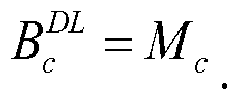
- B c DL represents the number of downlink sub-frames on a carrier c for which ACK/NACK needs to be fed back in the current uplink sub-frame.
- M c represents the number of all the downlink sub-frames (including special sub-frames) in the set of downlink sub-frames on the carrier c determined by the set of indexes, associated with the current uplink sub-frame, indicated by the reference TDD uplink/downlink configuration of the carrier c; or M c represents the number of downlink sub-frames, for which ACK/NACK needs to be fed back, in the set of downlink sub-frames on the carrier c determined by the set of indexes, associated with the current uplink sub-frame, indicated by the reference TDD uplink/downlink configuration of the carrier c.
- W DAI UL represents a value indicated in a DAI field in a PDCCH corresponding to a PUSCH of the current uplink sub-frame.
- U represents the maximum of U c corresponding to the respective carriers aggregated for the UE.
- U c represents the total number of downlink sub-frames in which PDSCHs are received and downlink sub-frames in which PDCCHs indicating Semi-Persistent Scheduling (SPS) resource release are received by the UE among the M c downlink sub-frames on the carrier c associated with the current uplink sub-frame.
- SPS Semi-Persistent Scheduling
- U c represents the total number of downlink sub-frames in which PDSCHs are transmitted and downlink sub-frames in which PDCCHs indicating SPS resource release are transmitted by the eNB among the M c downlink sub-frames on the carrier c associated with the current uplink sub-frame.
- Fig.2 an implementation of a method of determining the number of ACK/NACK feedback bits according to an embodiment of the invention is as illustrated in Fig.2 , where the method includes the following operations:
- Operation 100 judge whether there is a first category of carrier among carriers aggregated for a UE.
- operation 110 determine by a first category of scheme the number of downlink sub-frames, on each carrier c aggregated for the UE, for which ACK/NACK needs to be fed back in the current uplink sub-frame.
- the operation 120 is performed: determine by a second category of scheme the number of downlink sub-frames, on each carrier c aggregated for the UE, for which ACK/NACK needs to be fed back in the current uplink sub-frame.
- Operation 130 determine the number of ACK/NACK feedback bits to be fed back in the current uplink sub-frame according to the number of downlink sub-frames on each carrier c for which ACK/NACK needs to be fed back in the current uplink sub-frame.
- Operation 130 can be performed particularly as follows: the UE determines, from B c DL of the carrier c, the number of ACK/NACK feedback bits on the carrier c to be fed back in the current uplink sub-frame, and further determine the total number of ACK/NACK feedback bits to be fed back in the current uplink sub-frame.
- the method according to the embodiment of the invention proposes a specific solution to determine B c DL of the carrier so as to enable the system to operate normally in such an application scenario.
- the method according to the embodiment of the invention above can be applicable to both the UE side and the eNB side.
- corresponding ACK/NACK information can thereby be carried over a PUSCH of the current sub-frame and fed back to the eNB.
- corresponding ACK/NACK information can thereby be obtained over a PUSCH of the current sub-frame.
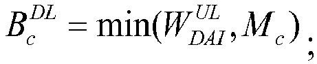
- the operation 110 can be performed particularly by determining, from at least one of M c , W DAI UL and U c , the number of downlink sub-frames, on each carrier c aggregated for the UE, for which ACK/NACK needs to be fed back in the current uplink sub-frame. This can be performed in any one of the following schemes:
- M c can be determined from the reference TDD uplink/downlink configuration of the carrier c in Table 2.
- B c DL is determined from respective M c .
- the UE doesn't need to take into account the number of actually received downlink sub-frames and the eNB doesn't need to take into account the number of actually transmitted downlink sub-frames, so B c DL determined by the UE side can be ensured the same as that determined by the UE side to thereby ensure reliability of data transmission.
- B c DL is determined in the same calculation formula to thereby facilitate popularized standardization of B c DL
- B c DL is determined in the same calculation formula to thereby facilitate popularized standardization of B c DL .
- B c DL determined in the formula provided in the scheme 3 agrees with the real number of scheduling sub-frames, so ACK/NACK can be transmitted over a PUSCH more effectively.
- the carriers aggregated for the UE can be further divided into a first set of carriers and a second set of carriers.
- the first set of carriers is the first category of carriers or such a part of carriers in the first category of carriers that are predefined or that are determined in signaling configuration information
- the second set of carriers is the other carriers than the first category of carriers among the carriers aggregated for the UE.
- the number of the downlink sub-frames, on each carrier c in each set of carriers, for which ACK/NACK needs to be fed back in the current uplink sub-frame is determined respectively.
- the operation 110 can be performed in any one of the following schemes:
- W DAI UL shall be determined from the largest number of scheduling sub-frames on the second set of carriers.
- W DAI UL shall be determined from the largest number of scheduling sub-frames on the second set of carriers.
- W DAI UL shall be determined from the largest number of scheduling sub-frames on the first set of carriers.
- W DAI UL shall be determined from the largest number of scheduling sub-frames on the first set of carriers.
- B c DL are determined by different methods respectively for the first set of carriers and the second set of carriers, so that the first set of carriers and the second set of carriers are independent from each other.
- B c DL determined by the UE side for one of the sets of carriers may disagree with the B c DL determined by eNB side for this set of carriers, which doesn't occur any influence on transmission of ACK/NACK for the other set of carriers.
- B c DL are determined by different methods respectively for the first set of carriers and the second set of carriers, so that the first set of carriers and the second set of carriers have low correlation with each other.
- B c DL determined by the UE side for one of the sets of carriers may disagree with the B c DL determined by eNB side for this set of carriers, the probability of an influence upon transmission of ACK/NACK for the other set of carriers is lowered as much as possible.
- B c DL of the respective carriers c can be determined particularly in any one of the schemes 1 to 3 above.
- the first category of carriers can be determined as the first set of carriers, and at this time the second set of carriers is a null set, and B c DL of the respective carriers c can be determined in any one of the schemes 4 to 14 above, and particularly B c DL of the first category of carriers c can be determined as done for the first set of carriers c in the schemes 4 to 14 without determining B c DL of the second set of carriers.
- the first set of carriers is such a part of carriers in the first category of carriers that are predefined or that are determined in signaling configuration information
- the second set of carriers is the other carriers than the first set of carriers among the carriers aggregated for the UE
- B c DL of the respective carriers c are determined in any of the schemes 4 to 14 above, and particularly B c DL of each carrier c in the first set of carriers are determined as done for the first set of carriers c in the schemes 4 to 14 and B c DL of each carrier c in the second set of carriers are determined as done for the second set of carriers c in the schemes 4 to 14, respectively.
- the predetermined rule is a rule predefined between the UE side and the eNB side, for example, the predetermined rule indicates that a PCC is the first set of carrier, or SCCs are the first set of carriers, or carriers with the highest or lowest M c are the first set of carrier, or the other carriers than the carriers with the highest or lowest M c among the carriers aggregated for the UE are the first set of carriers, and when there are a plurality of carriers with the same M c , at least one of them can be further selected according to carrier indexes to be the first set of carrier, for example, in an order of the ascending or descending carrier indexes.
- the notification signaling can be PDCCH signaling or Medium Access Control (MAC) signaling or Radio Resource Control (RRC) signaling.
- the method according to the embodiment of the invention can further include the following operations:
- the UE when carriers with different TDD uplink/downlink configurations are aggregated for a UE, the UE feeds back ACK/NACK over a PUSCH with a corresponding PDCCH in a sub-frame 2, the PDCCH includes a DAI field.
- a TDD uplink/downlink configuration of a PCC notified in SIB1 information is the configuration 2
- a TDD uplink/downlink configuration of an SCC notified in SIB1 information is the configuration 4.
- a reference TDD uplink/downlink configuration of the PCC is thereby determined as the configuration 2
- a reference TDD uplink/downlink configuration of the SCC is determined as the configuration 5.
- special sub-frames of the PCC and the SCC are neither the special sub-frame configurations 0 and 6 with a normal CP nor the special sub-frame configurations 0 and 4 with an extended CP.
- Fig.4 illustrates a condition of actual reception at the UE side.
- the SCC is the first category of carrier and determined to be the first set of carrier, and the PCC is the second set of carrier.
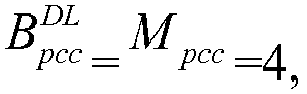
- B pcc DL of the PCC and B pcc DL of the SCC determined at the eNB side are the same as those determined at the UE side, which doesn't result in the problem of disagreement on understanding of the number of ACK/NACK feedback bits.
- the UE when carriers with different TDD uplink/downlink configurations are aggregated for a UE, the UE feeds back ACK/NACK over a PUSCH with a corresponding PDCCH in a sub-frame 2, the PDCCH includes a DAI field.
- a TDD uplink/downlink configuration of a PCC notified in SIR1 information is the configuration 3
- a TDD uplink/downlink configuration of an SCC notified in SIB1 information is the configuration 2.
- a reference TDD uplink/downlink configuration of the PCC is thereby determined as the configuration 3
- special sub-frames on the PCC correspond to the configuration 0 and the configuration 5 and are with a normal CP, or correspond to the configuration 0 and the configuration 4 and are with an extended CP.
- a reference TDD uplink/downlink configuration of the SCC is thereby determined as the configuration 5
- special sub-frames on the SCC correspond to the configuration 0 and the configuration 5 and are with a normal CP, or correspond to the configuration 0 and the configuration 4 and are with an extended CP.
- an actual condition of scheduling at the eNB side is the same as an actual condition of reception at the UE side, as illustrated in Fig.5 , where the actual condition of scheduling at the eNB side is the same as the actual condition of reception at the UE side, where "x" denotes that although the special sub-frames s1 and s6 belong to such a set of downlink sub-frames on the carrier associated with the sub-frame 2 that is determined by the reference TDD uplink/downlink configuration, since no ACK/NACK needs to be fed back for these special sub-frames, they are precluded from the M c downlink sub-frames for which ACK/NACK is fed back.
- the SCC is the first category of carrier and determined as the first set of carrier, and the PCC is the second set of carrier.
- B scc DL min ⁇ W DAI UL + 4 ⁇ U - W DAI UL / 4 ⁇
- B scc DL min ⁇ W DAI UL + 4 ⁇ U - W DAI UL / 4 ⁇
- B pcc DL of the PCC and B pcc DL of the SCC determined at the eNB side are the same as those determined at the UE side, which doesn't result in the problem of disagreement on understanding of the number of ACK/NACK feedback bits.
- an embodiment of the invention further provides an apparatus for determining the number of ACK/NACK feedback bits, and since the apparatus addresses the problems under a principle similar to the method of determining the number of ACK/NACK feedback bits, reference can be made to the implementation of the method for an implementation of the apparatus, so a repeated description thereof will be omitted here.
- an embodiment of the invention further provides an apparatus for determining the number of ACK/NACK feedback bits, an implementation of which is as illustrated in Fig.6 , where the structure of the apparatus includes the following modules:
- a carrier category judging module 1001 is configured to judge whether there is a first category of carrier among carriers aggregated for a UE.
- a first feedback sub-frame number determining module 1002 is configured, if there is the first category of carrier, to determine by a first category of scheme the number of downlink sub-frames, on each carrier c aggregated for the UE, for which ACK/NACK needs to be fed back in the current uplink sub-frame.
- a second feedback sub-frame number determining module 1003 is configured, if there is no first category of carrier, to determine by a second category of scheme the number of downlink sub-frames, on each carrier c aggregated for the UE, for which ACK/NACK needs to be fed back in the current uplink sub-frame.
- a feedback bit number determining module 1004 is to determine the number of ACK/NACK feedback bits to be fed back in the current uplink sub-frame from the number of downlink sub-frames on each carrier c for which ACK/NACK needs to be fed back in the current uplink sub-frame.
- the apparatus proposes a specific solution to determine B c DL of the carriers so as to enable the system to operate normally in such an application scenario.
- the first feedback sub-frame number determining module 1002 can be particularly configured to determine, from at least one of M c , W DAI UL and U c , the number of downlink sub-frames, on each carrier c aggregated for the UE, for which ACK/NACK needs to be fed back in the current uplink sub-frame; or to divide the carriers aggregated for the UE into a first set of carriers and a second set of carriers, where the first set of carriers is the first category of carriers or such a part of carriers in the first category of carriers that are predefined or that are determined in signaling configuration information, and the second set of carriers is the other carriers than the first category of carriers among the carriers aggregated for the UE, and to determine respectively the number of the downlink sub-frames, on each carrier c in each set of carriers, for which ACK/NACK needs to be fed back in the current uplink sub-frame.
- the apparatus according to the embodiment of the invention can be a UE or an eNB.
- the method and the apparatus according to the embodiments of the invention can be applicable to a scenario where a user equipment, which is configured to transmit ACK/NACK on PUCCH with the PUCCH format 3, transmits ACK/NACK over a PUSCH but also a scenario where a user equipment is configured to transmit ACK/NACK on PUCCH with another PUCCH transmission scheme.
- the method and the apparatus according to the embodiments of the invention can be applicable to a scenario where TDD carriers are aggregated but also to a scenario where a TDD carrier and an FDD carrier are aggregated, the TDD carrier acts as PCC, and DL HARQ timing of the FDD carrier corresponds to a TDD uplink/downlink configuration.
- the eNB includes at least an antenna, a processor and a memory, where the processor of the eNB is configured to perform the particular functions of carrier category judging module, the first feedback sub-frame number determining module, the second f feedback sub-frame number determining module, the third feedback sub-frame number determining module and the feedback bit number determining module in the apparatus according to the embodiment of the invention; and
- the eNB includes at least an antenna, a processor and a memory, where the processor of the UE is configured to perform the particular functions of the carrier category judging module, the first feedback sub-frame number determining module, the second feedback sub-frame number determining module, the third feedback sub-frame number determining module and the feedback bit number determining module in the apparatus according to the embodiment of the invention.
- the embodiments of the invention can be embodied as a method, a system or a computer program product. Therefore the invention can be embodied in the form of an all-hardware embodiment, an all-software embodiment or an embodiment of software and hardware in combination. Furthermore the invention can be embodied in the form of a computer program product embodied in one or more computer useable storage mediums (including but not limited to a disk memory, a CD-ROM, an optical memory, etc.) in which computer useable program codes are contained.
- a computer useable storage mediums including but not limited to a disk memory, a CD-ROM, an optical memory, etc.
- These computer program instructions can also be stored into a computer readable memory capable of directing the computer or the other programmable data processing device to operate in a specific manner so that the instructions stored in the computer readable memory create an article of manufacture including instruction means which perform the functions specified in the flow(s) of the flow chart and/or the block(s) of the block diagram.
- These computer program instructions can also be loaded onto the computer or the other programmable data processing device so that a series of operations are performed on the computer or the other programmable data processing device to create a computer implemented process so that the instructions executed on the computer or the other programmable device provide operations for performing the functions specified in the flow(s) of the flow chart and/or the block(s) of the block diagram.
Landscapes
- Engineering & Computer Science (AREA)
- Signal Processing (AREA)
- Computer Networks & Wireless Communication (AREA)
- Mobile Radio Communication Systems (AREA)
- Detection And Prevention Of Errors In Transmission (AREA)
- Time-Division Multiplex Systems (AREA)
Description
- This application claims the priority to Chinese Patent Application No.
201210210284.8 - The present invention relates to the field of wireless communications and particularly to a method of and apparatus for determining the number of ACK/NACK feedback bits.
- In a Long Term Evolution (LTE) system, a radio frame is divided into ten sub-frames, the length of each sub-frame is 1 millisecond (ms). Seven TDD uplink/downlink configurations are defined for a radio frame of a Time Division Duplex (TDD) system. As depicted in Table 1, D represents a downlink sub-frame, U represents an uplink sub-frame, and S represents a special sub-frame of the TDD system. The special sub-frame is composed of three components including a Downlink Pilot Time Slot (DwPTS), a Guard Period (GP) and an Uplink Pilot Time Slot (UpPTS).
Table 1 Uplink/downlink configuration Switching periodicity of downlink to uplink Sub-frame index 0 1 2 3 4 5 6 7 8 9 0 5 ms D S U U U D S U U U 1 5 ms D S U U D D S U U D 2 5 ms D S U D D D S U D D 3 10 ms D S U U U D D D D D 4 10 ms D S U U D D D D D D 5 10 ms D S U D D D D D D D 6 5 ms D S U U U D S U U D - Compared with the LTE system, Long Term Evolution-Advanced (LTE-A) system has significantly improved system peak data rates, which requires up to 1Gbps in the downlink and 500Mbps in the uplink. Thus a bandwidth available to a User Equipment (UE) (also referred to as a terminal) needs to be extended in the LTE-A system, that is, a plurality of consecutive or inconsecutive carriers served by the same evolved Node B (eNB) are aggregated together to serve the UE concurrently. These carriers aggregated together are referred to as Component Carriers (CCs). Each cell can be a component carrier, and the bandwidth of each component carrier is no larger than 20MHz to ensure backward compatibility with the LTE system.
- Intra-band carrier aggregation (CA) and inter-band carrier aggregation can be applicable dependent upon the bands where the aggregated carriers are located. In the Release-11 (Rel-11) and releases subsequent thereto, a UE in a system with carrier aggregation can share or access an adjacent band with another system. As illustrated in
Fig.1 , three carriers are aggregated for the UE, where thecarrier 1 and thecarrier 2 are located in theband 1 and thecarrier 3 is located in theband 2. In order to avoid uplink/downlink cross interference between the adjacent TDD systems, the UE shall use an uplink/downlink configuration on thecarrier 1 and thecarrier 2 which can coexist with the adjacent 3G/LTE TDD system in the band A, and the UE shall use an uplink/downlink configuration on thecarrier 3 which can coexist with the adjacent 3G/LTE TDD system in the band B. The so-called "coexist" refers to a configuration without uplink/downlink cross interference; for the LTE system, it refers to the same TDD uplink/downlink configuration. When the LTE system operates in the band A and the band B respectively with different TDD uplink/downlink configurations, the TDD uplink/downlink configuration of thecarriers carrier 3, that is, the carriers which have different TDD uplink/downlink configurations are aggregated for the UE. - The LTE-A UE needs to feed back Acknowledgment/Non-Acknowledgment (ACK/NACK) feedback information of a plurality of carriers (such as carriers of a TDD system and downlink carriers of a Frequency Division Duplex (FDD) system) and downlink sub-frames (where a special sub-frame is also considered as a downlink sub-frame because downlink data is transmitted in the DwPTS in the special sub-frame) in the same uplink sub-frame. The number of downlink sub-frames on a carrier for which ACK/NACK is fed back in the same sub-frame is defined as M, where the value of M differs from one uplink sub-frame to another and one TDD uplink/downlink configuration to another. Thus the value of M can be determined by the number of sub-frames in a set of downlink sub-frames associated with an uplink sub-frame in a corresponding TDD uplink/downlink configuration. The set of downlink sub-frames is composed of downlink sub-frames n-k associated with an uplink sub-frame n, where k a set of indexes K. For the different TDD uplink/downlink configurations, the values in the set of index K are as depicted in Table 2. In Table 2, for the respective TDD uplink/downlink configurations, each uplink sub-frame n corresponds respectively to a set of indexes K={k 0 ,k 1,···k M-1}. Particularly for special sub-frames with a downlink normal Cyclic Prefix (CP) and corresponding to
special sub-frame configurations 0 and 5 and special sub-frames with a downlink extended CP and corresponding tospecial sub-frame configurations 0 and 4, no ACK/NACK is fed back for these special sub-frames. In other words, when the set of downlink sub-frames corresponding to the uplink sub-frame n includes the special sub-frames with a downlink normal CP and corresponding tospecial sub-frame configurations 0 and 5 and/or the special sub-frames with a downlink extended CP and corresponding tospecial sub-frame configurations 0 and 4, M represents the number of downlink sub-frames other than the special sub-frames in the set of downlink sub-frames corresponding to the uplink sub-frame n; otherwise, M represents the number of all the downlink sub-frames in the set of downlink sub-frames associated with the uplink sub-frame n.Table 2 Uplink/downlink configuration Sub-frame number 0 1 2 3 4 5 6 7 8 9 0 - - 6 - 4 - - 6 - 4 1 - - 7, 6 4 - - - 7, 6 4 - 2 - - 8, 7, 4, 6 - - - - 8, 7, 4, 6 - - 3 - - 7, 6, 11 6, 5 5, 4 - - - - - 4 - - 12, 8, 7, 11 6, 5, 4, 7 - - - - - - 5 - - 13, 12, 9, 8, 7, 5, 4, 11, 6 - - - - - - - 6 - - 7 7 5 - - 7 7 - - Table 2 only depicts the relationship between the uplink sub-frame and the set of indexes K in a radio frame as an example, where n-k<0 represents an uplink sub-frame in a preceding radio frame.
- In the Rel-11, transmission of a Physical Uplink Control Channel (PUCCH) is only supported on a Primary Component Carrier (PCC). A downlink Hybrid Automatic Repeat reQuest (HARQ) timing relationship (simply DL HARQ timing) of the PCC is determined by a TDD uplink/downlink configuration notified to the PCC in a System Information Block (SIB) 1. The so-called DL HARQ timing refers to a relationship between a sub-frame (a downlink sub-frame or a special sub-frame) on a carrier and an uplink sub-frame in which ACK/NACK feedback information of the sub-frame is transmitted. When TDD uplink/downlink configurations, notified in the SIB1's corresponding to the respective carriers aggregated for the UE, are different, in order to feed back the ACK/NACK of a Secondary Component Carrier (SCC), that is, in order to locate an uplink sub-frame on the PCC in which ACK/NACK of a downlink sub-frame on the SCC is transmitted, DL HARQ timing of the SCC needs to be determined from a reference TDD uplink/downlink configuration, where the reference TDD uplink/downlink configuration may be a TDD uplink/downlink configuration notified to the SCC or the PCC in the SIB1 or an existing TDD uplink/downlink configuration other than the TDD uplink/downlink configuration above.
- In the scenario above, when ACK/NACK is transmitted on a Physical Uplink Shared Channel (PUSCH), for a PUSCH without any corresponding Physical Downlink Control Channel (PDCCH), the number of ACK/NACK bits of a carrier c carried in the current uplink sub-frame n can be determined from


- However there is no a specific solution to determine

- An object of the invention is to provide a method of and apparatus for determining the number of ACK/NACK feedback bits so as to address the problem of how to determine


- The object of the invention is attained in the following technical solutions:
- A method of determining the number of ACK/NACK feedback bits, wherein when carriers with different TDD uplink/downlink configurations are aggregated for a UE, and if the UE feeds back ACK/NACK over a PUSCH with a corresponding PDCCH, the PDCCH including a DAI field, the method including:
- judging whether there is a first category of carrier among carriers aggregated for a UE, wherein the first category of carrier refers to a carrier with a reference TDD uplink/downlink configuration being a first category of TDD uplink/downlink configuration and the first category of TDD uplink/downlink configuration refers to a TDD uplink/downlink configuration indicating a set of indexes, associated with an uplink sub-frame, in which the number of elements is larger than 4; or the first category of carrier refers to a carrier on which the number of downlink sub-frames for which ACK/NACK needs to be fed back among a set of downlink sub-frames is larger than 4, wherein the set of downlink sub-frames is determined according to a set of indexes, associated with an uplink sub-frame, indicated by a reference TDD uplink/downlink configuration of the carrier; wherein the reference TDD uplink/downlink configuration refers to a TDD uplink/downlink configuration for determining a relationship between a downlink sub-frame on the carrier and an uplink sub-frame in which ACK/NACK feedback information of the downlink sub-frame is transmitted;
- if there is the first category of carrier, then determining by a first category of scheme the number of downlink sub-frames, on each carrier c aggregated for the UE, for which ACK/NACK needs to be fed back in the current uplink sub-frame;
- if there is no first category of carrier, then determining by a second category of scheme the number of downlink sub-frames, on each carrier c aggregated for the UE, for which ACK/NACK needs to be fed back in the current uplink sub-frame; and
- determining the number of ACK/NACK feedback bits to be fed back in the current uplink sub-frame according to the number of downlink sub-frames on each carrier c for which ACK/NACK needs to be fed back in the current uplink sub-frame.
- An apparatus for determining the number of ACK/NACK feedback bits, wherein when carriers with different TDD uplink/downlink configurations are aggregated for a UE, and if the UE feeds back ACK/NACK over a PUSCH with a corresponding PDCCH, the PDCCH including a DAI field, the apparatus including:
- a carrier category judging module configured to judge whether there is a first category of carrier among carriers aggregated for a UE, wherein the first category of carrier refers to a carrier with a reference TDD uplink/downlink configuration being a first category of TDD uplink/downlink configuration and the first category of TDD uplink/downlink configuration refers to a TDD uplink/downlink configuration indicating a set of indexes, associated with an uplink sub-frame, in which the number of elements is larger than 4; or the first category of carrier refers to a carrier on which the number of downlink sub-frames for which ACK/NACK needs to be fed back among a set of downlink sub-frames is larger than 4, wherein the set of downlink sub-frames is determined according to a set of indexes, associated with an uplink sub-frame, indicated by a reference TDD uplink/downlink configuration of the carrier; wherein the reference TDD uplink/downlink configuration refers to a TDD uplink/downlink configuration for determining a relationship between a downlink sub-frame on the carrier and an uplink sub-frame in which ACK/NACK feedback information of the downlink sub-frame is transmitted;
- a first feedback sub-frame number determining module configured, if there is the first category of carrier, to determine by a first category of scheme the number of downlink sub-frames, on each carrier c aggregated for the UE, for which ACK/NACK needs to be fed back in the current uplink sub-frame;
- a second feedback sub-frame number determining module configured, if there is no first category of carrier, to determine by a second category of scheme the number of downlink sub-frames, on each carrier c aggregated for the UE, for which ACK/NACK needs to be fed back in the current uplink sub-frame; and
- a feedback bit number determining module configured to determine the number of ACK/NACK feedback bits to be fed back in the current uplink sub-frame according to the number of downlink sub-frames on each carrier c for which ACK/NACK needs to be fed back in the current uplink sub-frame.
- When carriers with different TDD uplink/downlink configurations are aggregated for a UE, if the UE feeds back ACK/NACK over a PUSCH with a corresponding PDCCH including a DAI field, the method according to the embodiment of the invention proposes a specific solution to determine

-
-
Fig.1 is a schematic diagram of inter-band carrier aggregation; -
Fig.2 is a flow chart of a method according to an embodiment of the invention; -
Fig.3 is a schematic diagram of resources at the eNB side in an application scenario according to an embodiment of the invention; -
Fig.4 is a schematic diagram of resources at the UE side in an application scenario according to an embodiment of the invention; -
Fig.5 is a schematic diagram of resources in another application scenario according to an embodiment of the invention; and -
Fig.6 is a schematic structural diagram of an apparatus according to an embodiment of the invention. - For a UE with inter-band carrier aggregation, when carriers with different TDD uplink/downlink configurations are aggregated for the UE, and if the UE feeds back ACK/NACK over a PUSCH with a corresponding PDCCH which includes a Downlink Assignment Index (DAI) field, embodiments of the invention provide a method of and apparatus for determining the number of ACK/NACK feedback bits for this case.
- Prior to a description of the respective embodiments of the invention, firstly some technical features as referred to in the invention may be defined below:
- A first category of carrier refers to a carrier with a reference TDD uplink/downlink configuration being a first category of TDD uplink/downlink configuration. Correspondingly the first category of TDD uplink/downlink configuration refers to a TDD uplink/downlink configuration indicating a set of indexes, associated with an uplink sub-frame, in which the number of elements is larger than 4. For example, there is a carrier with a reference TDD uplink/downlink configuration being the TDD uplink/
downlink configuration 5, where the number of elements in a set of indexes K = {4, 5, 6, 7, 8, 9, 11, 12, 13} associated with an uplink sub-frame indicated by the TDD uplink/downlink configuration 5 is 9. - Or,
- The first category of carrier refers to a carrier on which the number of downlink sub-frames for which ACK/NACK needs to be fed back among a set of downlink sub-frames is larger than 4, wherein the set of downlink sub-frames is determined according to a set of indexes, associated with an uplink sub-frame, indicated by a reference TDD uplink/downlink configuration of the carrier. The number of downlink sub-frames for which ACK/NACK needs to be fed back can be defined as the number of all the downlink sub-frames (including special sub-frames) in the set of downlink sub-frames on the carrier determined by the set of indexes associated with an uplink sub-frame, wherein the set of indexes is indicated by the reference TDD uplink/downlink configuration of the carrier; or the number of downlink sub-frames for which ACK/NACK needs to be fed back can be defined as the number of all the downlink sub-frames, other than special sub-frames for which no ACK/NACK needs to be fed back, in the set of downlink sub-frames on the carrier determined by the set of indexes associated with an uplink sub-frame, wherein the set of indexes is indicated by the reference TDD uplink/downlink configuration of the carrier, where the special sub-frames for which no ACK/NACK needs to be fed back refer to special sub-frames with a downlink normal CP and corresponding to
special sub-frame configurations 0 and 5 and special sub-frames with a downlink extended CP and corresponding tospecial sub-frame configurations 0 and 4. For example, there is a carrier with a reference TDD uplink/downlink configuration which is the TDD uplink/downlink configuration 5 and with a TDD uplink/downlink configuration indicated in an SIB1 as other than the TDD uplink/downlink configuration 0. Assumed that the reference TDD uplink/downlink configuration of the carrier is the TDD uplink/downlink configuration 5 and the TDD uplink/downlink configuration indicated in the SIB1 is the TDD uplink/downlink configuration 1, where the number of downlink sub-frames in a set of downlink sub-frames on the carrier determined by the set of indexes associated with an uplink sub-frame indicated by the reference TDD uplink/downlink configuration of the carrier is 6. - In a practical application, the definition of the first category of carrier can be specified in a standard or agreed on in advance between the UE and an eNB, and the invention may not be limited to either of the definitions above.
- The reference TDD uplink/downlink configuration of a carrier refers to a TDD uplink/downlink configuration by which a relationship (i.e., DL HARQ timing) is determined between a downlink sub-frame on the carrier and an uplink sub-frame in which ACK/NACK feedback information of the downlink sub-frame is transmitted.
- The reference TDD uplink/downlink configuration of a PCC refers to a TDD uplink/downlink configuration notified to the PCC in an
SIB 1. - The reference TDD uplink/downlink configuration of an SCC refers to a TDD uplink/downlink configuration determined from TDD uplink/downlink configurations respectively notified to the SCC and the PCC in SIB1, particularly as specified in the communication standard, so a repeated description thereof may be omitted here.

- Mc represents the number of all the downlink sub-frames (including special sub-frames) in the set of downlink sub-frames on the carrier c determined by the set of indexes, associated with the current uplink sub-frame, indicated by the reference TDD uplink/downlink configuration of the carrier c; or
Mc represents the number of downlink sub-frames, for which ACK/NACK needs to be fed back, in the set of downlink sub-frames on the carrier c determined by the set of indexes, associated with the current uplink sub-frame, indicated by the reference TDD uplink/downlink configuration of the carrier c. If the set of downlink sub-frames on the carrier c determined by the set of indexes, associated with the current uplink sub-frame, indicated by the reference TDD uplink/downlink configuration of the carrier c precludes the special sub-frames which correspond tospecial sub-frame configurations 0 and 5 and are with a downlink normal CP or the special sub-frames which correspond tospecial sub-frame configurations 0 and 4 and are with a downlink extended CP, then


- U represents the maximum of Uc corresponding to the respective carriers aggregated for the UE.
- For the UE side, Uc represents the total number of downlink sub-frames in which PDSCHs are received and downlink sub-frames in which PDCCHs indicating Semi-Persistent Scheduling (SPS) resource release are received by the UE among the Mc downlink sub-frames on the carrier c associated with the current uplink sub-frame.
- For the eNB side, Uc represents the total number of downlink sub-frames in which PDSCHs are transmitted and downlink sub-frames in which PDCCHs indicating SPS resource release are transmitted by the eNB among the Mc downlink sub-frames on the carrier c associated with the current uplink sub-frame.
- Based upon the application scenario above, an implementation of a method of determining the number of ACK/NACK feedback bits according to an embodiment of the invention is as illustrated in
Fig.2 , where the method includes the following operations: - Operation 100: judge whether there is a first category of carrier among carriers aggregated for a UE.
- If there is the first category of carrier, then
operation 110 is performed: determine by a first category of scheme the number of downlink sub-frames, on each carrier c aggregated for the UE, for which ACK/NACK needs to be fed back in the current uplink sub-frame. - If there is no first category of carrier, then the
operation 120 is performed: determine by a second category of scheme the number of downlink sub-frames, on each carrier c aggregated for the UE, for which ACK/NACK needs to be fed back in the current uplink sub-frame. - The
operation 120 can be performed particularly by obtaining

- Operation 130: determine the number of ACK/NACK feedback bits to be fed back in the current uplink sub-frame according to the number of downlink sub-frames on each carrier c for which ACK/NACK needs to be fed back in the current uplink sub-frame.
-
Operation 130 can be performed particularly as follows: the UE determines, from


- When carriers with different TDD uplink/downlink configurations are aggregated for a UE, and if the UE feeds back ACK/NACK over a PUSCH with a corresponding PDCCH which includes a DAI field, the method according to the embodiment of the invention proposes a specific solution to determine

- The method according to the embodiment of the invention above can be applicable to both the UE side and the eNB side.
- For the UE side, after the number of ACK/NACK feedback bits to be fed back in the current uplink sub-frame is determined by the method according to the embodiment of the invention, corresponding ACK/NACK information can thereby be carried over a PUSCH of the current sub-frame and fed back to the eNB.
- For the eNB side, after the number of ACK/NACK feedback bits to be fed back in the current uplink sub-frame is determined by the method according to the embodiment of the invention, corresponding ACK/NACK information can thereby be obtained over a PUSCH of the current sub-frame.
- The
operation 110 can be performed particularly by determining, from at least one of Mc,
-
Operation 110 is performed particularly by obtaining Mc of each carrier c and determining, from Mc , the number

- For the carrier c, Mc can be determined from the reference TDD uplink/downlink configuration of the carrier c in Table 2.
- In the
scheme 1, for the respective carriers c aggregated for the UE,


-
Operation 110 is performed particularly by obtaining


- In the
scheme 2, for the each carrier c aggregated for the UE,

-
Operation 110 is performed particularly by obtaining


- With the
scheme 3, preferably it shall be ensured by the eNB side that the largest number S1 of scheduling sub-frames on a first set of carriers and the largest number S2 of scheduling sub-frames on a second set of carriers satisfy: mod(S1-S2,4) =0 or 4└(S 1-1)/4┘ ≤ S 1 - S 2 ≤ S 1 or S2<=mod(S1-1,4)+1 or S2>=S1. - In the
scheme 3, for the each carrier c aggregated for the UE,


scheme 3 agrees with the real number of scheduling sub-frames, so ACK/NACK can be transmitted over a PUSCH more effectively. - In a particular implementation of the
operation 110, the carriers aggregated for the UE can be further divided into a first set of carriers and a second set of carriers. The first set of carriers is the first category of carriers or such a part of carriers in the first category of carriers that are predefined or that are determined in signaling configuration information, and the second set of carriers is the other carriers than the first category of carriers among the carriers aggregated for the UE. The number of the downlink sub-frames, on each carrier c in each set of carriers, for which ACK/NACK needs to be fed back in the current uplink sub-frame is determined respectively. Particularly theoperation 110 can be performed in any one of the following schemes: - The
operation 110 is performed particularly by obtaining Mc of each carrier c in the first set of carriers and determining the number


- With the
scheme 4, preferably
- The
operation 110 is performed particularly by obtaining Mc of each carrier c in the first set of carriers and determining the number


- With the
scheme 5, preferably
- The
operation 110 is performed particularly by obtaining


- With the
scheme 6, preferably
- The
operation 110 is performed particularly by obtaining


- With the
scheme 7, preferably
- The
operation 110 is performed particularly by obtaining


- With the
scheme 8, preferably it shall be ensured by the eNB side that the largest number S1 of scheduling sub-frames on the first set of carriers and the largest number S2 of scheduling sub-frames on the second set of carriers satisfy: mod(S1-S2,4) =0 or 4└(S 1-1)/4┘≤S 1 - S 2 ≤ S 1 or S2<=mod(S1-1,4)+1 or S2>=S1. - The
operation 110 is performed particularly by obtaining


- With the
scheme 9, preferably it shall be ensured by the eNB side that the largest number S1 of scheduling sub-frames on the first set of carriers and the largest number S2 of scheduling sub-frames on the second set of carriers satisfy: mod(S1-S2,4) =0 or 4└(S 1 -1)/4┘ ≤ S 1 - S2 ≤ S 1 or S2<=mod(S1-1,4)+1 or S2>=S1. - The
operation 110 is performed particularly by obtaining


- With the scheme 10, preferably it shall be ensured by the eNB side that the largest number S1 of scheduling sub-frames on the first set of carriers and the largest number S2 of scheduling sub-frames on the second set of carriers satisfy: mod(S1-S2,4) =0 or 4└(S1-1)/4┘ ≤ S 1 - S 2 ≤ S 1 or S2<=mod(S1-1,4)+ or S2>=S1.
- The
operation 110 is performed particularly by obtaining


- With the scheme 11, preferably it shall be ensured by the eNB side that the largest number S1 of scheduling sub-frames on the first set of carriers and the largest number S2 of scheduling sub-frames on the second set of carriers satisfy: mod(S1-S2,4) =0 or 4└(S 1 -1)/4┘≤ S 1 - S 2 ≤ S 1 or S2<=mod(S1-1,4)+1 or S2>=S1.
- In the
above scheme 4 to the scheme 11,


- The
operation 110 is performed particularly by obtaining


- The
operation 110 is performed particularly by obtaining


- The
operation 110 is performed particularly by obtaining


- In the
above scheme 12 to the scheme 14,


- If all the carriers aggregated for the UE are the first category of carriers, then

schemes 1 to 3 above. Alternatively the first category of carriers can be determined as the first set of carriers, and at this time the second set of carriers is a null set, and
schemes 4 to 14 above, and particularly
schemes 4 to 14 without determining

schemes 4 to 14 above, and particularly
schemes 4 to 14 and
schemes 4 to 14, respectively. The predetermined rule is a rule predefined between the UE side and the eNB side, for example, the predetermined rule indicates that a PCC is the first set of carrier, or SCCs are the first set of carriers, or carriers with the highest or lowest Mc are the first set of carrier, or the other carriers than the carriers with the highest or lowest Mc among the carriers aggregated for the UE are the first set of carriers, and when there are a plurality of carriers with the same Mc , at least one of them can be further selected according to carrier indexes to be the first set of carrier, for example, in an order of the ascending or descending carrier indexes. Particularly the notification signaling can be PDCCH signaling or Medium Access Control (MAC) signaling or Radio Resource Control (RRC) signaling. - Before the
operation 110, the method according to the embodiment of the invention can further include the following operations: - judge whether Mc of the carrier c is 0, and if Mc =0, then the number of downlink carriers on the carrier c for which ACK/NACK needs to be fed back in the current uplink sub-frame is determined to be 0; otherwise, dependent upon the result of judgment in the
operation 100 above, perform theoperation 110 in which the number of downlink carriers on the carrier c for which ACK/NACK needs to be fed back in the current uplink sub-frame is determined by any one of the schemes above, or perform theoperation 120. - The method according to the embodiment of the invention will be described below in details with reference to the drawings and particular application scenarios thereof.
- In an application scenario, when carriers with different TDD uplink/downlink configurations are aggregated for a UE, the UE feeds back ACK/NACK over a PUSCH with a corresponding PDCCH in a
sub-frame 2, the PDCCH includes a DAI field. A TDD uplink/downlink configuration of a PCC notified in SIB1 information is theconfiguration 2, and a TDD uplink/downlink configuration of an SCC notified in SIB1 information is theconfiguration 4. A reference TDD uplink/downlink configuration of the PCC is thereby determined as theconfiguration 2, and a reference TDD uplink/downlink configuration of the SCC is determined as theconfiguration 5. Moreover special sub-frames of the PCC and the SCC are neither thespecial sub-frame configurations 0 and 6 with a normal CP nor thespecial sub-frame configurations 0 and 4 with an extended CP. Correspondingly the number of downlink sub-frames in a set of downlink sub-frames on the PCC associated with the current uplink sub-frame is


Fig.3 illustrates a condition of actual scheduling at the eNB side. At the eNB side, Upcc =2, Uscc =7 and U = max(Upcc ,Uscc ) =7.Fig.4 illustrates a condition of actual reception at the UE side. At the UE side, Upcc =2, Uscc =6 and U = max(Upcc ,Uscc )=6. Based upon such an application scenario, the SCC is the first category of carrier and determined to be the first set of carrier, and the PCC is the second set of carrier. - If the number of sub-frames on a carrier for which ACK/NACK needs to be fed back in the current uplink sub-frame is determined by the
scheme 1 at the UE side and the eNB side, then the value of


- If the number of sub-frames on a carrier for which ACK/NACK needs to be fed back in the current uplink sub-frame is determined by the
scheme 2 at the UE side and the eNB side, and assumed that


- If the number of sub-frames on a carrier for which ACK/NACK needs to be fed back in the current uplink sub-frame is determined by the scheme 3 at the UE side and the eNB side, and assumed that


- If the number of sub-frames on a carrier for which ACK/NACK needs to be fed back in the current uplink sub-frame is determined by the
scheme 4 at the UE side and the eNB side, and assumed that




- If the number of sub-frames on a carrier for which ACK/NACK needs to be fed back in the current uplink sub-frame is determined by the
scheme 5 at the UE side and the eNB side, and assumed that


- If the number of sub-frames on a carrier for which ACK/NACK needs to be fed back in the current uplink sub-frame is determined by the
scheme 6 at the UE side and the eNB side, and assumed that


- If the number of sub-frames on a carrier for which ACK/NACK needs to be fed back in the current uplink sub-frame is determined by the
scheme 7 at the UE side and the eNB side, and assumed that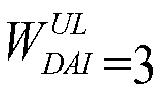


- If the number of sub-frames on a carrier for which ACK/NACK needs to be fed back in the current uplink sub-frame is determined by the
scheme 8 at the UE side and the eNB side, and assumed that


- If the number of sub-frames on a carrier for which ACK/NACK needs to be fed back in the current uplink sub-frame is determined by the
scheme 9 at the UE side and the eNB side, and assumed that


- If the number of sub-frames on a carrier for which ACK/NACK needs to be fed back in the current uplink sub-frame is determined by the scheme 10 at the UE side and the eNB side, and assumed that




- If the number of sub-frames on a carrier for which ACK/NACK needs to be fed back in the current uplink sub-frame is determined by the scheme 11 at the UE side and the eNB side, and assumed that


- If the number of sub-frames on a carrier for which ACK/NACK needs to be fed back in the current uplink sub-frame is determined by any one of the
schemes 12 to 14 at the UE side and the eNB side, and assumed that




- In another application scenario, when carriers with different TDD uplink/downlink configurations are aggregated for a UE, the UE feeds back ACK/NACK over a PUSCH with a corresponding PDCCH in a
sub-frame 2, the PDCCH includes a DAI field. A TDD uplink/downlink configuration of a PCC notified in SIR1 information is theconfiguration 3, and a TDD uplink/downlink configuration of an SCC notified in SIB1 information is theconfiguration 2. A reference TDD uplink/downlink configuration of the PCC is thereby determined as theconfiguration 3, the number of downlink sub-frames on the PCC in a set of downlink sub-frames associated with theuplink sub-frame 2 is
configuration 5 and are with a normal CP, or correspond to the configuration 0 and theconfiguration 4 and are with an extended CP. Correspondingly the number of downlink sub-frames on the PCC for which ACK/NACK needs to be fed back in the set of downlink sub-frames associated with the current uplink sub-frame is
configuration 5, the number of downlink sub-frames on the PCC in the set of downlink sub-frames associated with theuplink sub-frame 2 is
configuration 5 and are with a normal CP, or correspond to the configuration 0 and theconfiguration 4 and are with an extended CP. Correspondingly the number of downlink sub-frames on the SCC for which ACK/NACK needs to be fed back in the set of downlink sub-frames associated with the current uplink sub-frame is
Fig.5 , where the actual condition of scheduling at the eNB side is the same as the actual condition of reception at the UE side, where "x" denotes that although the special sub-frames s1 and s6 belong to such a set of downlink sub-frames on the carrier associated with thesub-frame 2 that is determined by the reference TDD uplink/downlink configuration, since no ACK/NACK needs to be fed back for these special sub-frames, they are precluded from the Mc downlink sub-frames for which ACK/NACK is fed back. At the eNB side, Upcc =1, Uscc =5 and U = max(Upcc ,Uscc )=5. At the UE side, Upcc = 1, Uscc =5 and U = max(Upcc,Uscc =5.
- If the number of sub-frames on a carrier for which ACK/NACK needs to be fed back in the current uplink sub-frame is determined by the
scheme 1 at the UE side and the eNB side, then the value of


- If the number of sub-frames on a carrier for which ACK/NACK needs to be fed back in the current uplink sub-frame is determined by the
scheme 2 at the UE side and the eNB side, then the number of sub-frames on the PCC for which ACK/NACK needs to be fed back in the current uplink sub-frame is

- If the number of sub-frames on a carrier for which ACK/NACK needs to be fed back in the current uplink sub-frame is determined by the
scheme 3 at the UE side and the eNB side, since S2=1 corresponding to the PCC and S1=5 corresponding to the SCC satisfy mod(S1-S2,4) =0 or 4└(S 1-1)/4┘≤S 1-S 2≤S 1 or S2<=mod(S1-1,4)+1, then the number of sub-frames on the PCC for which ACK/NACK needs to be fed back in the current uplink sub-frame is

- If the number of sub-frames on a carrier for which ACK/NACK needs to be fed back in the current uplink sub-frame is determined by the
scheme 4 at the UE side and the eNB side, then the number of sub-frames on the PCC for which ACK/NACK needs to be fed back in the current uplink sub-frame is

- If the number of sub-frames on a carrier for which ACK/NACK needs to be fed back in the current uplink sub-frame is determined by the
scheme 5 at the UE side and the eNB side, then the number of sub-frames on the PCC for which ACK/NACK needs to be fed back in the current uplink sub-frame is

- If the number of sub-frames on a carrier for which ACK/NACK needs to be fed back in the current uplink sub-frame is determined by the
scheme 6 at the UE side and the eNB side, then the number of sub-frames on the PCC for which ACK/NACK needs to be fed back in the current uplink sub-frame is

- If the number of sub-frames on a carrier for which ACK/NACK needs to be fed back in the current uplink sub-frame is determined by the
scheme 7 at the UE side and the eNB side, then the number of sub-frames on the PCC for which ACK/NACK needs to be fed back in the current uplink sub-frame is

- If the number of sub-frames on a carrier for which ACK/NACK needs to be fed back in the current uplink sub-frame is determined by the
scheme 8 at the UE side and the eNB side, since S2=1 corresponding to the PCC and S1=5 corresponding to the SCC satisfy mod(S1-S2,4) =0 or 4└(S 1-1)/4┘≤S 1 -S 2≤S 1 or S2<=mod(S1-1,4)+1, then the number of sub-frames on the PCC for which ACK/NACK needs to be fed back in the current uplink sub-frame is

- If the number of sub-frames on a carrier for which ACK/NACK needs to be fed back in the current uplink sub-frame is determined by the
scheme 9 at the UE side and the eNB side, since S2=1 corresponding to the PCC and S1=5 corresponding to the SCC satisfy mod(S1-S2,4) =0 or 4└(S 1-1)/4┘≤S 1 -S 2≤S 1 or S2<=mod(S1-1,4)+1, then the number of sub-frames on the PCC for which ACK/NACK needs to be fed back in the current uplink sub-frame is

- If the number of sub-frames on a carrier for which ACK/NACK needs to be fed back in the current uplink sub-frame is determined by the scheme 10 at the UE side and the eNB side, since S2=1 corresponding to the PCC and S1=5 corresponding to the SCC satisfy mod(S1-S2,4) =0 or 4└(S 1-1)/4┘≤S 1 -S 2≤S 1 or S2<=mod(S1-1,4)+1, then the number of sub-frames on the PCC for which ACK/NACK needs to be fed back in the current uplink sub-frame is


- If the number of sub-frames on a carrier for which ACK/NACK needs to be fed back in the current uplink sub-frame is determined by the scheme 11 at the UE side and the eNB side, since S2=1 corresponding to the PCC and S1=5 corresponding to the SCC satisfy mod(S1-S2,4) =0 or 4└(S 1-1)/4┘≤S 1 -S 2≤S 1 or S2<=mod(S1-1,4)+1, then the number of sub-frames on the PCC for which ACK/NACK needs to be fed back in the current uplink sub-frame is


- If the number of sub-frames on a carrier for which ACK/NACK needs to be fed back in the current uplink sub-frame is determined by any one of the
schemes 12 to 14 at the UE side and the eNB side, then due to U = 5>1, the number of sub-frames on the PCC for which ACK/NACK needs to be fed back in the current uplink sub-frame is



- Based upon the same inventive idea, an embodiment of the invention further provides an apparatus for determining the number of ACK/NACK feedback bits, and since the apparatus addresses the problems under a principle similar to the method of determining the number of ACK/NACK feedback bits, reference can be made to the implementation of the method for an implementation of the apparatus, so a repeated description thereof will be omitted here.
- When carriers with different TDD uplink/downlink configurations are aggregated for a UE, if the UE feeds back ACK/NACK over a PUSCH with a corresponding PDCCH, the PDCCH includes a DAI field, an embodiment of the invention further provides an apparatus for determining the number of ACK/NACK feedback bits, an implementation of which is as illustrated in
Fig.6 , where the structure of the apparatus includes the following modules: - A carrier
category judging module 1001 is configured to judge whether there is a first category of carrier among carriers aggregated for a UE. - A first feedback sub-frame
number determining module 1002 is configured, if there is the first category of carrier, to determine by a first category of scheme the number of downlink sub-frames, on each carrier c aggregated for the UE, for which ACK/NACK needs to be fed back in the current uplink sub-frame. - A second feedback sub-frame
number determining module 1003 is configured, if there is no first category of carrier, to determine by a second category of scheme the number of downlink sub-frames, on each carrier c aggregated for the UE, for which ACK/NACK needs to be fed back in the current uplink sub-frame. - The second feedback sub-frame
number determining module 1003 is particularly configured to obtain


- A feedback bit
number determining module 1004 is to determine the number of ACK/NACK feedback bits to be fed back in the current uplink sub-frame from the number of downlink sub-frames on each carrier c for which ACK/NACK needs to be fed back in the current uplink sub-frame. - When carriers with different TDD uplink/downlink configurations are aggregated for a UE, and if the UE feeds back ACK/NACK over a PUSCH with a corresponding PDCCH which includes a DAI field, the apparatus according to the embodiment of the invention proposes a specific solution to determine

- In the apparatus according to the embodiment of the invention, the first feedback sub-frame
number determining module 1002 can be particularly configured to determine, from at least one of Mc ,
- When the first feedback sub-frame
number determining module 1002 is configured to determine, from at least one of Mc ,
number determining module 1002 can be particularly configured to obtain Mc of each carrier c; and to determine from Mc the number

- When the first feedback sub-frame
number determining module 1002 is configured to determine from at least one of Mc ,
number determining module 1002 can be particularly configured to obtain


- When the first feedback sub-frame
number determining module 1002 is configured to determine from at least one of Mc ,
number determining module 1002 can be particularly configured to obtain


- When the first feedback sub-frame number determining module 1002 is configured to divide the carriers aggregated for the UE into the first set of carriers and the second set of carriers and to determine respectively the number of the downlink sub-frames, on each carrier c in each set of carriers, for which ACK/NACK needs to be fed back in the current uplink sub-frame, the first feedback sub-frame number determining module 1002 can be particularly configured to obtain Mc of each carrier c in the first set of carriers and to determine the number




- When the first feedback sub-frame number determining module 1002 is configured to divide the carriers aggregated for the UE into the first set of carriers and the second set of carriers and to determine respectively the number of the downlink sub-frames, on each carrier c in each set of carriers, for which ACK/NACK needs to be fed back in the current uplink sub-frame, the first feedback sub-frame number determining module 1002 can be particularly configured to obtain


- When the first feedback sub-frame number determining module 1002 is configured to divide the carriers aggregated for the UE into the first set of carriers and the second set of carriers and to determine respectively the number of the downlink sub-frames, on each carrier c in each set of carriers, for which ACK/NACK needs to be fed back in the current uplink sub-frame, the first feedback sub-frame number determining module 1002 can be particularly configured to obtain


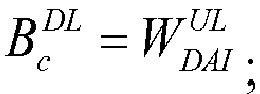


- When the first feedback sub-frame number determining module 1002 is configured to divide the carriers aggregated for the UE into the first set of carriers and the second set of carriers and to determine respectively the number of the downlink sub-frames, on each carrier c in each set of carriers, for which ACK/NACK needs to be fed back in the current uplink sub-frame, the first feedback sub-frame number determining module 1002 can be particularly configured to obtain


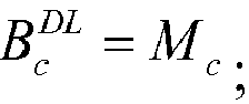


- The apparatus according to the embodiment of the invention can further include a third feedback bit number determining module, configured to judge whether Mc of the carrier c is 0, and if Mc =0, to determine the number of sub-frames on the carrier c for which ACK/NACK needs to be fed back in the current uplink sub-frame to be 0; otherwise, to trigger the first feedback bit
number determining module 1002 or the second feedback bitnumber determining module 1003 into operation dependent upon the result of judgment by the carriercategory judging module 1001. - The apparatus according to the embodiment of the invention can be a UE or an eNB.
- It shall be noted that the method and the apparatus according to the embodiments of the invention can be applicable to a scenario where a user equipment, which is configured to transmit ACK/NACK on PUCCH with the
PUCCH format 3, transmits ACK/NACK over a PUSCH but also a scenario where a user equipment is configured to transmit ACK/NACK on PUCCH with another PUCCH transmission scheme. - It shall be noted that the method and the apparatus according to the embodiments of the invention can be applicable to a scenario where TDD carriers are aggregated but also to a scenario where a TDD carrier and an FDD carrier are aggregated, the TDD carrier acts as PCC, and DL HARQ timing of the FDD carrier corresponds to a TDD uplink/downlink configuration.
- The structure of and processing by the apparatus according to the embodiment of the invention will be described below with respect to preferred structures thereof in hardware.
- If the apparatus according to the embodiment of the invention is an eNB, then the eNB includes at least an antenna, a processor and a memory, where the processor of the eNB is configured to perform the particular functions of carrier category judging module, the first feedback sub-frame number determining module, the second f feedback sub-frame number determining module, the third feedback sub-frame number determining module and the feedback bit number determining module in the apparatus according to the embodiment of the invention; and
- If the apparatus according to the embodiment of the invention is a UE, then the eNB includes at least an antenna, a processor and a memory, where the processor of the UE is configured to perform the particular functions of the carrier category judging module, the first feedback sub-frame number determining module, the second feedback sub-frame number determining module, the third feedback sub-frame number determining module and the feedback bit number determining module in the apparatus according to the embodiment of the invention.
- Those skilled in the art shall appreciate that the embodiments of the invention can be embodied as a method, a system or a computer program product. Therefore the invention can be embodied in the form of an all-hardware embodiment, an all-software embodiment or an embodiment of software and hardware in combination. Furthermore the invention can be embodied in the form of a computer program product embodied in one or more computer useable storage mediums (including but not limited to a disk memory, a CD-ROM, an optical memory, etc.) in which computer useable program codes are contained.
- The invention has been described in a flow chart and/or a block diagram of the method, the device (system) and the computer program product according to the embodiments of the invention. It shall be appreciated that respective flows and/or blocks in the flow chart and/or the block diagram and combinations of the flows and/or the blocks in the flow chart and/or the block diagram can be embodied in computer program instructions. These computer program instructions can be loaded onto a general-purpose computer, a specific-purpose computer, an embedded processor or a processor of another programmable data processing device to produce a machine so that the instructions executed on the computer or the processor of the other programmable data processing device create means for performing the functions specified in the flow(s) of the flow chart and/or the block(s) of the block diagram.
- These computer program instructions can also be stored into a computer readable memory capable of directing the computer or the other programmable data processing device to operate in a specific manner so that the instructions stored in the computer readable memory create an article of manufacture including instruction means which perform the functions specified in the flow(s) of the flow chart and/or the block(s) of the block diagram.
- These computer program instructions can also be loaded onto the computer or the other programmable data processing device so that a series of operations are performed on the computer or the other programmable data processing device to create a computer implemented process so that the instructions executed on the computer or the other programmable device provide operations for performing the functions specified in the flow(s) of the flow chart and/or the block(s) of the block diagram.
- Although the preferred embodiments of the invention have been described, those skilled in the art benefiting from the underlying inventive concept can make additional modifications and variations to these embodiments. Therefore the appended claims are intended to be construed as encompassing the preferred embodiments and all the modifications and variations coming into the scope of the invention.
- Evidently those skilled in the art can make various modifications and variations to the invention without departing from the spirit and scope of the invention. Thus the invention is also intended to encompass these modifications and variations thereto so long as the modifications and variations come into the scope of the claims appended to the invention and their equivalents.
Claims (18)
- A method of determining the number of Acknowledgment/Non-Acknowledgment (ACK/NACK) feedback bits, wherein when carriers with different Time Division Duplex (TDD) uplink/downlink configurations are aggregated for a User Equipment (UE), and if the UE feeds back ACK/NACK over a Physical Uplink Shared Channel (PUSCH) with a corresponding Physical Downlink Control Channel (PDCCH), the PDCCH including a Downlink Assignment Index (DAI) field, the method comprising:judging whether there is a first category of carrier among carriers aggregated for a UE, wherein the first category of carrier refers to a carrier with a reference TDD uplink/downlink configuration being a first category of TDD uplink/downlink configuration and the first category of TDD uplink/downlink configuration refers to a TDD uplink/downlink configuration indicating a set of indexes, associated with an uplink sub-frame, in which the number of elements is larger than 4; or the first category of carrier refers to a carrier on which the number of downlink sub-frames for which ACK/NACK needs to be fed back among a set of downlink sub-frames is larger than 4, wherein the set of downlink sub-frames is determined according to a set of indexes, associated with an uplink sub-frame, indicated by a reference TDD uplink/downlink configuration of the carrier ; wherein the reference TDD uplink/downlink configuration refers to a TDD uplink/downlink configuration for determining a relationship between a downlink sub-frame on the carrier and an uplink sub-frame in which ACK/NACK feedback information of the downlink sub-frame is transmitted;if there is the first category of carrier, then determining by a first category of scheme the number of downlink sub-frames, on each carrier c aggregated for the UE, for which ACK/NACK needs to be fed back in the current uplink sub-frame;if there is no first category of carrier, then determining by a second category of scheme the number of downlink sub-frames, on each carrier c aggregated for the UE, for which ACK/NACK needs to be fed back in the current uplink sub-frame; anddetermining the number of ACK/NACK feedback bits to be fed back in the current uplink sub-frame according to the number of downlink sub-frames on each carrier c for which ACK/NACK needs to be fed back in the current uplink sub-frame.
- The method according to claim 1, wherein if there is the first category of carrier, then determining by the first category of scheme the number of downlink sub-frames, on each carrier c aggregated for the UE, for which ACK/NACK needs to be fed back in the current uplink sub-frame particularly comprises:Determining, from at least one of Mc ,
 dividing the carriers aggregated for the UE into a first set of carriers and a second set of carriers, wherein the first set of carriers is the first category of carriers or a part of the first category of carriers that are predefined or that are determined from the signaling configuration information, and the second set of carriers is the other carriers than the first category of carriers among the carriers aggregated for the UE, and determining respectively the number of the downlink sub-frames, on each carrier c in each set of carriers, for which ACK/NACK needs to be fed back in the current uplink sub-frame;wherein
- The method according to claim 2, wherein the number of downlink sub-frames, represented by Mc , for which ACK/NACK needs to be fed back is:the number of all the downlink sub-frames in the set of downlink sub-frames on the carrier c determined by the set of indexes, associated with the current uplink sub-frame, indicated by the reference TDD uplink/downlink configuration of the carrier c; orif the set of downlink sub-frames on the carrier c determined by the set of indexes, associated with the current uplink sub-frame, indicated by the reference TDD uplink/downlink configuration of the carrier c precludes special sub-frames with corresponding special sub-frame configurations 0 and 5 and with a downlink normal CP or special sub-frames with corresponding special sub-frame configurations 0 and 4 and with a downlink extended CP, then


- The method according to claim 2, wherein determining, from at least one of Mc ,
 obtaining Mc of each carrier c; anddetermining from Mc the number

- The method according to claim 2, wherein determining, from at least one of Mc ,
 obtaining

 or,obtaining


- The method according to claim 2, wherein dividing the carriers aggregated for the UE into the first set of carriers and the second set of carriers and determining respectively the number of the downlink sub-frames, on each carrier c in each set of carriers, for which ACK/NACK needs to be fed back in the current uplink sub-frame particularly comprises:obtaining Mc of each carrier c in the first set of carriers and determining the number


 or,obtaining Mc of each carrier c in the first set of carriers and determining the number


- The method according to claim 2, wherein dividing the carriers aggregated for the UE into the first set of carriers and the second set of carriers and determining respectively the number of the downlink sub-frames, on each carrier c in each set of carriers, for which ACK/NACK needs to be fed back in the current uplink sub-frame particularly comprises:obtaining


 or,obtaining


- The method according to claim 2, wherein dividing the carriers aggregated for the UE into the first set of carriers and the second set of carriers and determining respectively the number of the downlink sub-frames, on each carrier c in each set of carriers, for which ACK/NACK needs to be fed back in the current uplink sub-frame particularly comprises:obtaining


 orobtaining


 orobtaining


 orobtaining




- The method according to claim 2, wherein dividing the carriers aggregated for the UE into the first set of carriers and the second set of carriers and determining respectively the number of the downlink sub-frames, on each carrier c in each set of carriers, for which ACK/NACK needs to be fed back in the current uplink sub-frame particularly comprises:obtaining



 orobtaining


 orobtaining


- The method according to claim 1, wherein if there is no first category of carrier, then determining by the second category of scheme the number of downlink sub-frames, on each carrier c aggregated for the UE, for which ACK/NACK needs to be fed back in the current uplink sub-frame particularly comprises:obtaining
 determining the number

- The method according to any one of claims 1 to 10, wherein before the number of downlink sub-frames, on each carrier c aggregated for the UE, for which ACK/NACK needs to be fed back in the current uplink sub-frame is determined, the method further comprises:judging whether Mc of the carrier c is 0, and if Mc =0, then determining the number of downlink sub-frames on the carrier c for which ACK/NACK needs to be fed back in the current uplink sub-frame to be 0.
- An apparatus for determining the number of ACK/NACK feedback bits, wherein when carriers with different TDD uplink/downlink configurations are aggregated for a UE, and if the UE feeds back ACK/NACK over a PUSCH with a corresponding PDCCH, the PDCCH including a DAI field, the apparatus comprising:a carrier category judging module configured to judge whether there is a first category of carrier among carriers aggregated for a UE, wherein the first category of carrier refers to a carrier with a reference TDD uplink/downlink configuration being a first category of TDD uplink/downlink configuration and the first category of TDD uplink/downlink configuration refers to a TDD uplink/downlink configuration indicating a set of indexes, associated with an uplink sub-frame, in which the number of elements is larger than 4; or the first category of carrier refers to a carrier on which the number of downlink sub-frames for which ACK/NACK needs to be fed back among a set of downlink sub-frames is larger than 4, wherein the set of downlink sub-frames is determined according to a set of indexes, associated with an uplink sub-frame, indicated by a reference TDD uplink/downlink configuration of the carrier; wherein the reference TDD uplink/downlink configuration refers to a TDD uplink/downlink configuration for determining a relationship between a downlink sub-frame on the carrier and an uplink sub-frame in which ACK/NACK feedback information of the downlink sub-frames is transmitted;a first feedback sub-frame number determining module configured, if there is the first category of carrier, to determine by a first category of scheme the number of downlink sub-frames, on each carrier c aggregated for the UE, for which ACK/NACK needs to be fed back in the current uplink sub-frame;a second feedback sub-frame number determining module configured, if there is no first category of carrier, to determine by a second category of scheme the number of downlink sub-frames, on each carrier c aggregated for the UE, for which ACK/NACK needs to be fed back in the current uplink sub-frame; anda feedback bit number determining module configured to determine the number of ACK/NACK feedback bits to be fed back in the current uplink sub-frame according to the number of downlink sub-frames on each carrier c for which ACK/NACK needs to be fed back in the current uplink sub-frame.
- The apparatus according to claim 12, wherein the first feedback sub-frame number determining module is configured:to determine, from at least one of Mc ,
 to divide the carriers aggregated for the UE into a first set of carriers and a second set of carriers, wherein the first set of carriers is the first category of carriers or a part of the first category of carriers that are predefined or that are determined from the signaling configuration information, and the second set of carriers is the other carriers than the first category of carriers among the carriers aggregated for the UE, and to determine respectively the number of the downlink sub-frames, on each carrier c in each set of carriers, for which ACK/NACK needs to be fed back in the current uplink sub-frame;wherein
- The apparatus according to claim 13, wherein the first feedback sub-frame number determining module configured to determine, from at least one of Mc ,
 to obtain Mc of each carrier c; and to determine from Mc the number
 orto obtain


wherein U represents the maximum of Uc corresponding to the respective carriers aggregated for the UE;orto obtain


- The apparatus according to claim 13, wherein the first feedback sub-frame number determining module configured to divide the carriers aggregated for the UE into the first set of carriers and the second set of carriers and to determine respectively the number of the downlink sub-frames, on each carrier c in each set of carriers, for which ACK/NACK needs to be fed back in the current uplink sub-frame is particularly configured:to obtain Mc of each carrier c in the first set of carriers and to determine the number


 or
or
to obtain Mc of each carrier c in the first set of carriers and to determine the number


 to obtain


 orto obtain


 orto obtain


 orto obtain


 orto obtain


 orto obtain


 orto obtain


 orto obtain


 orto obtain


- The apparatus according to claim 12, wherein the second feedback sub-frame number determining module is particularly configured to obtain


- The apparatus according to any one of claims 12 to 16, wherein the apparatus further comprises a third feedback bit number determining module, configured to judge whether Mc of the carrier c is 0, and if Mc =0, to determine the number of sub-frames on the carrier c for which ACK/NACK needs to be fed back in the current uplink sub-frame to be 0; otherwise, to trigger the first feedback bit number determining module or the second feedback bit number determining module into operation dependent upon the result of judgment by the carrier category judging module.
- The apparatus according to any one of claims 12 to 16, wherein the apparatus is a user equipment or the apparatus is a base station.
Applications Claiming Priority (2)
| Application Number | Priority Date | Filing Date | Title |
|---|---|---|---|
| CN201210210284.8A CN103516499B (en) | 2012-06-19 | 2012-06-19 | A kind of ACK/NACK number of bits of feedback determines method and device |
| PCT/CN2013/077050 WO2013189252A1 (en) | 2012-06-19 | 2013-06-09 | Ack/nack feedback bit number determination method and device |
Publications (3)
| Publication Number | Publication Date |
|---|---|
| EP2863574A1 true EP2863574A1 (en) | 2015-04-22 |
| EP2863574A4 EP2863574A4 (en) | 2015-07-22 |
| EP2863574B1 EP2863574B1 (en) | 2017-08-09 |
Family
ID=49768103
Family Applications (1)
| Application Number | Title | Priority Date | Filing Date |
|---|---|---|---|
| EP13806080.1A Active EP2863574B1 (en) | 2012-06-19 | 2013-06-09 | Ack/nack feedback bit number determination method and device |
Country Status (8)
| Country | Link |
|---|---|
| US (1) | US9705655B2 (en) |
| EP (1) | EP2863574B1 (en) |
| JP (1) | JP6139674B2 (en) |
| KR (2) | KR20150020708A (en) |
| CN (1) | CN103516499B (en) |
| ES (1) | ES2644605T3 (en) |
| TW (1) | TWI492567B (en) |
| WO (1) | WO2013189252A1 (en) |
Cited By (2)
| Publication number | Priority date | Publication date | Assignee | Title |
|---|---|---|---|---|
| EP3370362A4 (en) * | 2016-03-25 | 2019-11-27 | Guangdong OPPO Mobile Telecommunications Corp., Ltd. | METHOD AND APPARATUS FOR TRANSMITTING FEEDBACK INFORMATION |
| EP4472115A2 (en) | 2017-08-11 | 2024-12-04 | Huawei Technologies Co., Ltd. | Method for determining feedback information, terminal device, and network device |
Families Citing this family (14)
| Publication number | Priority date | Publication date | Assignee | Title |
|---|---|---|---|---|
| WO2010114252A2 (en) | 2009-03-29 | 2010-10-07 | Lg Electronics Inc. | Method for transmitting control information in wireless communication system and apparatus therefor |
| CN104904154B (en) | 2013-01-03 | 2018-06-19 | Lg电子株式会社 | For sending the method and apparatus of uplink signal in a wireless communication system |
| US9706568B2 (en) * | 2013-06-28 | 2017-07-11 | Texas Instruments Incorporated | Uplink control signaling for joint FDD and TDD carrier aggregation |
| CN103944701B (en) * | 2013-08-26 | 2017-08-08 | 上海朗帛通信技术有限公司 | Transmission method and device in a kind of TDD FDD association systems |
| CN104683076B (en) * | 2013-12-02 | 2018-03-23 | 中国移动通信集团公司 | Response message feedback method, response message method of reseptance and relevant apparatus |
| CN105099633B (en) * | 2014-04-25 | 2019-08-09 | 北京三星通信技术研究有限公司 | Transmission method and device for physical downlink shared channel |
| US10230516B2 (en) * | 2014-05-18 | 2019-03-12 | Lg Electronics Inc. | Method and apparatus for transmitting and receiving feedback information in wireless access system supporting FDR transmission |
| CN112953698B (en) | 2015-07-01 | 2023-07-07 | Lg电子株式会社 | Method, base station and processor for receiving HARQ-ACK in CA wireless communication system |
| US10841935B2 (en) * | 2015-08-31 | 2020-11-17 | Ntt Docomo, Inc. | User terminal, radio base station and radio communication method |
| EP3440790B1 (en) * | 2016-04-07 | 2020-03-04 | Telefonaktiebolaget LM Ericsson (publ) | Radio-network node, wireless device and methods performed therein |
| CN105959088B (en) * | 2016-07-18 | 2019-04-05 | 珠海市魅族科技有限公司 | HARQ feedback method, HARQ feedback device, base station and terminal |
| CN106059739B (en) * | 2016-07-18 | 2019-06-18 | 珠海市魅族科技有限公司 | HARQ feedback method, HARQ feedback device, base station and terminal |
| CN109716694B (en) * | 2016-11-04 | 2021-03-30 | 华为技术有限公司 | HARQ-ACK feedback information transmission method and related device |
| WO2020029287A1 (en) * | 2018-08-10 | 2020-02-13 | Oppo广东移动通信有限公司 | Method for feeding back information, and terminal, chip and storage medium |
Family Cites Families (12)
| Publication number | Priority date | Publication date | Assignee | Title |
|---|---|---|---|---|
| US8565167B2 (en) * | 2009-07-02 | 2013-10-22 | Nokia Corporation | System and methods for ACK/NAK feedback in TDD communications |
| US8848623B2 (en) * | 2009-08-21 | 2014-09-30 | Blackberry Limited | System and method for channel timing offset |
| CN102025466B (en) * | 2009-09-15 | 2013-10-02 | 华为技术有限公司 | Signal processing method, base station and user equipment |
| US9112692B2 (en) * | 2010-08-16 | 2015-08-18 | Qualcomm Incorporated | ACK/NACK transmission for multi-carrier operation |
| US10873425B2 (en) | 2010-11-12 | 2020-12-22 | Qualcomm Incorporated | Acknowledgement / negative acknowledgement feedback for TDD |
| CN102136894B (en) * | 2011-04-12 | 2013-10-16 | 电信科学技术研究院 | Method and device for determining ACK (acknowledgement)/NACK (negative Acknowledgement) feedback bit number |
| CN103493419B (en) * | 2011-05-17 | 2016-08-17 | Lg电子株式会社 | Method for sending control information and device used for the method |
| CN103095433B (en) * | 2011-11-04 | 2018-06-15 | 北京三星通信技术研究有限公司 | A kind of method for sending HARQ-ACK feedback information |
| CN104160649B (en) * | 2012-03-09 | 2018-05-29 | Lg电子株式会社 | Method and device for transmitting and receiving signals |
| US9526091B2 (en) * | 2012-03-16 | 2016-12-20 | Intel Corporation | Method and apparatus for coordination of self-optimization functions in a wireless network |
| US9749094B2 (en) * | 2012-06-14 | 2017-08-29 | Sharp Kabushiki Kaisha | Devices for sending and receiving feedback information |
| US9306721B2 (en) * | 2013-03-15 | 2016-04-05 | Google Technology Holdings LLC | Method and apparatus for device-to-device communication |
-
2012
- 2012-06-19 CN CN201210210284.8A patent/CN103516499B/en active Active
-
2013
- 2013-06-09 WO PCT/CN2013/077050 patent/WO2013189252A1/en not_active Ceased
- 2013-06-09 KR KR1020157001376A patent/KR20150020708A/en not_active Abandoned
- 2013-06-09 ES ES13806080.1T patent/ES2644605T3/en active Active
- 2013-06-09 US US14/409,363 patent/US9705655B2/en active Active
- 2013-06-09 KR KR1020177007127A patent/KR101805563B1/en active Active
- 2013-06-09 EP EP13806080.1A patent/EP2863574B1/en active Active
- 2013-06-09 JP JP2015517593A patent/JP6139674B2/en active Active
- 2013-06-19 TW TW102121687A patent/TWI492567B/en active
Cited By (5)
| Publication number | Priority date | Publication date | Assignee | Title |
|---|---|---|---|---|
| EP3370362A4 (en) * | 2016-03-25 | 2019-11-27 | Guangdong OPPO Mobile Telecommunications Corp., Ltd. | METHOD AND APPARATUS FOR TRANSMITTING FEEDBACK INFORMATION |
| US10701721B2 (en) | 2016-03-25 | 2020-06-30 | Guangdong Oppo Mobile Telecommunications Corp., Ltd. | Method and apparatus for transmitting feedback information |
| US20200288493A1 (en) | 2016-03-25 | 2020-09-10 | Guangdong Oppo Mobile Telecommunications Corp., Ltd. | Method and apparatus for transmitting feedback information |
| US11122603B2 (en) | 2016-03-25 | 2021-09-14 | Guangdong Oppo Mobile Telecommunications Corp., Ltd. | Method and apparatus for transmitting feedback information |
| EP4472115A2 (en) | 2017-08-11 | 2024-12-04 | Huawei Technologies Co., Ltd. | Method for determining feedback information, terminal device, and network device |
Also Published As
| Publication number | Publication date |
|---|---|
| CN103516499A (en) | 2014-01-15 |
| KR20170032493A (en) | 2017-03-22 |
| EP2863574A4 (en) | 2015-07-22 |
| KR101805563B1 (en) | 2017-12-07 |
| WO2013189252A1 (en) | 2013-12-27 |
| TW201401806A (en) | 2014-01-01 |
| EP2863574B1 (en) | 2017-08-09 |
| TWI492567B (en) | 2015-07-11 |
| US9705655B2 (en) | 2017-07-11 |
| JP2015526947A (en) | 2015-09-10 |
| US20150188687A1 (en) | 2015-07-02 |
| CN103516499B (en) | 2017-06-13 |
| KR20150020708A (en) | 2015-02-26 |
| ES2644605T3 (en) | 2017-11-29 |
| JP6139674B2 (en) | 2017-05-31 |
Similar Documents
| Publication | Publication Date | Title |
|---|---|---|
| EP2863574B1 (en) | Ack/nack feedback bit number determination method and device | |
| EP2846488B1 (en) | Carrier aggregation feedback method, device and system for different tdd uplink/downlink configurations | |
| EP2824860B1 (en) | Harq feedback implementation method and device | |
| EP2844003B1 (en) | Downlink control signalling transmission method and device | |
| EP2871883B1 (en) | Dci transmission method and device under cross-band carrier aggregation | |
| EP3047592B1 (en) | Method and system for harq operation and scheduling in joint tdd and fdd carrier aggregation | |
| EP3742647B1 (en) | Method and device for sending hybrid automatic retransmission request acknowledge information | |
| EP2525597B1 (en) | Detection method and detection device of downlink control information | |
| EP2744139B1 (en) | Uplink feedback method and apparatus | |
| US9461780B2 (en) | Method and apparatus for transmitting hybrid automatic repeat request acknowledgement information | |
| US9137796B2 (en) | Method and apparatus for monitoring scheduling information | |
| EP4156582A1 (en) | Harq-ack information feedback method and apparatus | |
| US20170054532A1 (en) | Node and method for downlink scheduling and hybrid automatic repeat request timing | |
| EP2582170A1 (en) | Method and user equipment for detecting downlink control information in carrier aggregation scenario | |
| EP3251260B1 (en) | Harq-ack information feedback method and apparatus | |
| EP2833571B1 (en) | Method for implementing harq feedback, and method and device for allocating uplink subframe | |
| EP3163781B1 (en) | Carrier aggregation method and apparatus for communication system | |
| EP2728781A1 (en) | Method, system and apparatus for sending and receiving feedback information | |
| US10075261B2 (en) | Method and device for performing HARQ |
Legal Events
| Date | Code | Title | Description |
|---|---|---|---|
| PUAI | Public reference made under article 153(3) epc to a published international application that has entered the european phase |
Free format text: ORIGINAL CODE: 0009012 |
|
| 17P | Request for examination filed |
Effective date: 20150108 |
|
| AK | Designated contracting states |
Kind code of ref document: A1 Designated state(s): AL AT BE BG CH CY CZ DE DK EE ES FI FR GB GR HR HU IE IS IT LI LT LU LV MC MK MT NL NO PL PT RO RS SE SI SK SM TR |
|
| AX | Request for extension of the european patent |
Extension state: BA ME |
|
| RA4 | Supplementary search report drawn up and despatched (corrected) |
Effective date: 20150619 |
|
| RIC1 | Information provided on ipc code assigned before grant |
Ipc: H04L 5/00 20060101AFI20150615BHEP Ipc: H04L 1/16 20060101ALI20150615BHEP Ipc: H04L 5/14 20060101ALI20150615BHEP |
|
| DAX | Request for extension of the european patent (deleted) | ||
| 17Q | First examination report despatched |
Effective date: 20160610 |
|
| STAA | Information on the status of an ep patent application or granted ep patent |
Free format text: STATUS: EXAMINATION IS IN PROGRESS |
|
| GRAP | Despatch of communication of intention to grant a patent |
Free format text: ORIGINAL CODE: EPIDOSNIGR1 |
|
| STAA | Information on the status of an ep patent application or granted ep patent |
Free format text: STATUS: GRANT OF PATENT IS INTENDED |
|
| INTG | Intention to grant announced |
Effective date: 20170208 |
|
| GRAS | Grant fee paid |
Free format text: ORIGINAL CODE: EPIDOSNIGR3 |
|
| GRAA | (expected) grant |
Free format text: ORIGINAL CODE: 0009210 |
|
| STAA | Information on the status of an ep patent application or granted ep patent |
Free format text: STATUS: THE PATENT HAS BEEN GRANTED |
|
| AK | Designated contracting states |
Kind code of ref document: B1 Designated state(s): AL AT BE BG CH CY CZ DE DK EE ES FI FR GB GR HR HU IE IS IT LI LT LU LV MC MK MT NL NO PL PT RO RS SE SI SK SM TR |
|
| REG | Reference to a national code |
Ref country code: GB Ref legal event code: FG4D |
|
| REG | Reference to a national code |
Ref country code: AT Ref legal event code: REF Ref document number: 917904 Country of ref document: AT Kind code of ref document: T Effective date: 20170815 Ref country code: CH Ref legal event code: EP |
|
| REG | Reference to a national code |
Ref country code: NL Ref legal event code: FP |
|
| REG | Reference to a national code |
Ref country code: IE Ref legal event code: FG4D |
|
| REG | Reference to a national code |
Ref country code: DE Ref legal event code: R096 Ref document number: 602013024878 Country of ref document: DE |
|
| REG | Reference to a national code |
Ref country code: LT Ref legal event code: MG4D |
|
| REG | Reference to a national code |
Ref country code: AT Ref legal event code: MK05 Ref document number: 917904 Country of ref document: AT Kind code of ref document: T Effective date: 20170809 |
|
| PG25 | Lapsed in a contracting state [announced via postgrant information from national office to epo] |
Ref country code: NO Free format text: LAPSE BECAUSE OF FAILURE TO SUBMIT A TRANSLATION OF THE DESCRIPTION OR TO PAY THE FEE WITHIN THE PRESCRIBED TIME-LIMIT Effective date: 20171109 Ref country code: LT Free format text: LAPSE BECAUSE OF FAILURE TO SUBMIT A TRANSLATION OF THE DESCRIPTION OR TO PAY THE FEE WITHIN THE PRESCRIBED TIME-LIMIT Effective date: 20170809 Ref country code: SE Free format text: LAPSE BECAUSE OF FAILURE TO SUBMIT A TRANSLATION OF THE DESCRIPTION OR TO PAY THE FEE WITHIN THE PRESCRIBED TIME-LIMIT Effective date: 20170809 Ref country code: HR Free format text: LAPSE BECAUSE OF FAILURE TO SUBMIT A TRANSLATION OF THE DESCRIPTION OR TO PAY THE FEE WITHIN THE PRESCRIBED TIME-LIMIT Effective date: 20170809 Ref country code: AT Free format text: LAPSE BECAUSE OF FAILURE TO SUBMIT A TRANSLATION OF THE DESCRIPTION OR TO PAY THE FEE WITHIN THE PRESCRIBED TIME-LIMIT Effective date: 20170809 Ref country code: FI Free format text: LAPSE BECAUSE OF FAILURE TO SUBMIT A TRANSLATION OF THE DESCRIPTION OR TO PAY THE FEE WITHIN THE PRESCRIBED TIME-LIMIT Effective date: 20170809 |
|
| PG25 | Lapsed in a contracting state [announced via postgrant information from national office to epo] |
Ref country code: BG Free format text: LAPSE BECAUSE OF FAILURE TO SUBMIT A TRANSLATION OF THE DESCRIPTION OR TO PAY THE FEE WITHIN THE PRESCRIBED TIME-LIMIT Effective date: 20171109 Ref country code: PL Free format text: LAPSE BECAUSE OF FAILURE TO SUBMIT A TRANSLATION OF THE DESCRIPTION OR TO PAY THE FEE WITHIN THE PRESCRIBED TIME-LIMIT Effective date: 20170809 Ref country code: LV Free format text: LAPSE BECAUSE OF FAILURE TO SUBMIT A TRANSLATION OF THE DESCRIPTION OR TO PAY THE FEE WITHIN THE PRESCRIBED TIME-LIMIT Effective date: 20170809 Ref country code: IS Free format text: LAPSE BECAUSE OF FAILURE TO SUBMIT A TRANSLATION OF THE DESCRIPTION OR TO PAY THE FEE WITHIN THE PRESCRIBED TIME-LIMIT Effective date: 20171209 Ref country code: RS Free format text: LAPSE BECAUSE OF FAILURE TO SUBMIT A TRANSLATION OF THE DESCRIPTION OR TO PAY THE FEE WITHIN THE PRESCRIBED TIME-LIMIT Effective date: 20170809 Ref country code: GR Free format text: LAPSE BECAUSE OF FAILURE TO SUBMIT A TRANSLATION OF THE DESCRIPTION OR TO PAY THE FEE WITHIN THE PRESCRIBED TIME-LIMIT Effective date: 20171110 |
|
| PG25 | Lapsed in a contracting state [announced via postgrant information from national office to epo] |
Ref country code: RO Free format text: LAPSE BECAUSE OF FAILURE TO SUBMIT A TRANSLATION OF THE DESCRIPTION OR TO PAY THE FEE WITHIN THE PRESCRIBED TIME-LIMIT Effective date: 20170809 Ref country code: CZ Free format text: LAPSE BECAUSE OF FAILURE TO SUBMIT A TRANSLATION OF THE DESCRIPTION OR TO PAY THE FEE WITHIN THE PRESCRIBED TIME-LIMIT Effective date: 20170809 Ref country code: DK Free format text: LAPSE BECAUSE OF FAILURE TO SUBMIT A TRANSLATION OF THE DESCRIPTION OR TO PAY THE FEE WITHIN THE PRESCRIBED TIME-LIMIT Effective date: 20170809 |
|
| REG | Reference to a national code |
Ref country code: DE Ref legal event code: R097 Ref document number: 602013024878 Country of ref document: DE |
|
| PG25 | Lapsed in a contracting state [announced via postgrant information from national office to epo] |
Ref country code: SM Free format text: LAPSE BECAUSE OF FAILURE TO SUBMIT A TRANSLATION OF THE DESCRIPTION OR TO PAY THE FEE WITHIN THE PRESCRIBED TIME-LIMIT Effective date: 20170809 Ref country code: EE Free format text: LAPSE BECAUSE OF FAILURE TO SUBMIT A TRANSLATION OF THE DESCRIPTION OR TO PAY THE FEE WITHIN THE PRESCRIBED TIME-LIMIT Effective date: 20170809 Ref country code: SK Free format text: LAPSE BECAUSE OF FAILURE TO SUBMIT A TRANSLATION OF THE DESCRIPTION OR TO PAY THE FEE WITHIN THE PRESCRIBED TIME-LIMIT Effective date: 20170809 |
|
| PLBE | No opposition filed within time limit |
Free format text: ORIGINAL CODE: 0009261 |
|
| STAA | Information on the status of an ep patent application or granted ep patent |
Free format text: STATUS: NO OPPOSITION FILED WITHIN TIME LIMIT |
|
| REG | Reference to a national code |
Ref country code: FR Ref legal event code: PLFP Year of fee payment: 6 |
|
| 26N | No opposition filed |
Effective date: 20180511 |
|
| PG25 | Lapsed in a contracting state [announced via postgrant information from national office to epo] |
Ref country code: SI Free format text: LAPSE BECAUSE OF FAILURE TO SUBMIT A TRANSLATION OF THE DESCRIPTION OR TO PAY THE FEE WITHIN THE PRESCRIBED TIME-LIMIT Effective date: 20170809 |
|
| REG | Reference to a national code |
Ref country code: CH Ref legal event code: PL |
|
| REG | Reference to a national code |
Ref country code: IE Ref legal event code: MM4A |
|
| PG25 | Lapsed in a contracting state [announced via postgrant information from national office to epo] |
Ref country code: LU Free format text: LAPSE BECAUSE OF NON-PAYMENT OF DUE FEES Effective date: 20180609 Ref country code: MC Free format text: LAPSE BECAUSE OF FAILURE TO SUBMIT A TRANSLATION OF THE DESCRIPTION OR TO PAY THE FEE WITHIN THE PRESCRIBED TIME-LIMIT Effective date: 20170809 |
|
| PG25 | Lapsed in a contracting state [announced via postgrant information from national office to epo] |
Ref country code: LI Free format text: LAPSE BECAUSE OF NON-PAYMENT OF DUE FEES Effective date: 20180630 Ref country code: IE Free format text: LAPSE BECAUSE OF NON-PAYMENT OF DUE FEES Effective date: 20180609 Ref country code: CH Free format text: LAPSE BECAUSE OF NON-PAYMENT OF DUE FEES Effective date: 20180630 |
|
| PG25 | Lapsed in a contracting state [announced via postgrant information from national office to epo] |
Ref country code: MT Free format text: LAPSE BECAUSE OF NON-PAYMENT OF DUE FEES Effective date: 20180609 |
|
| PG25 | Lapsed in a contracting state [announced via postgrant information from national office to epo] |
Ref country code: TR Free format text: LAPSE BECAUSE OF FAILURE TO SUBMIT A TRANSLATION OF THE DESCRIPTION OR TO PAY THE FEE WITHIN THE PRESCRIBED TIME-LIMIT Effective date: 20170809 |
|
| PG25 | Lapsed in a contracting state [announced via postgrant information from national office to epo] |
Ref country code: PT Free format text: LAPSE BECAUSE OF FAILURE TO SUBMIT A TRANSLATION OF THE DESCRIPTION OR TO PAY THE FEE WITHIN THE PRESCRIBED TIME-LIMIT Effective date: 20170809 |
|
| PG25 | Lapsed in a contracting state [announced via postgrant information from national office to epo] |
Ref country code: MK Free format text: LAPSE BECAUSE OF NON-PAYMENT OF DUE FEES Effective date: 20170809 Ref country code: CY Free format text: LAPSE BECAUSE OF FAILURE TO SUBMIT A TRANSLATION OF THE DESCRIPTION OR TO PAY THE FEE WITHIN THE PRESCRIBED TIME-LIMIT Effective date: 20170809 Ref country code: HU Free format text: LAPSE BECAUSE OF FAILURE TO SUBMIT A TRANSLATION OF THE DESCRIPTION OR TO PAY THE FEE WITHIN THE PRESCRIBED TIME-LIMIT; INVALID AB INITIO Effective date: 20130609 |
|
| PG25 | Lapsed in a contracting state [announced via postgrant information from national office to epo] |
Ref country code: AL Free format text: LAPSE BECAUSE OF FAILURE TO SUBMIT A TRANSLATION OF THE DESCRIPTION OR TO PAY THE FEE WITHIN THE PRESCRIBED TIME-LIMIT Effective date: 20170809 |
|
| REG | Reference to a national code |
Ref country code: DE Ref legal event code: R081 Ref document number: 602013024878 Country of ref document: DE Owner name: DATANG MOBILE COMMUNICATIONS EQUIPMENT CO., LT, CN Free format text: FORMER OWNER: CHINA ACADEMY OF TELECOMMUNICATIONS TECHNOLOGY, BEIJING, CN |
|
| REG | Reference to a national code |
Ref country code: NL Ref legal event code: PD Owner name: DATANG MOBILE COMMUNICATIONS EQUIPMENT CO., LTD.; CN Free format text: DETAILS ASSIGNMENT: CHANGE OF OWNER(S), ASSIGNMENT; FORMER OWNER NAME: CHINA ACADEMY OF TELECOMMUNICATIONS TECHNOLOGY Effective date: 20210730 |
|
| REG | Reference to a national code |
Ref country code: ES Ref legal event code: PC2A Owner name: DATANG MOBILE COMMUNICATIONS EQUIPMENT CO., LTD Effective date: 20210826 |
|
| REG | Reference to a national code |
Ref country code: BE Ref legal event code: PD Owner name: DATANG MOBILE COMMUNICATIONS EQUIPMENT CO., LTD.; CN Free format text: DETAILS ASSIGNMENT: CHANGE OF OWNER(S), ASSIGNMENT; FORMER OWNER NAME: CHINA ACADEMY OF TELECOMMUNICATIONS TECHNOLOGY Effective date: 20210816 |
|
| REG | Reference to a national code |
Ref country code: GB Ref legal event code: 732E Free format text: REGISTERED BETWEEN 20211007 AND 20211013 |
|
| P01 | Opt-out of the competence of the unified patent court (upc) registered |
Effective date: 20230512 |
|
| PGFP | Annual fee paid to national office [announced via postgrant information from national office to epo] |
Ref country code: DE Payment date: 20250618 Year of fee payment: 13 |
|
| PGFP | Annual fee paid to national office [announced via postgrant information from national office to epo] |
Ref country code: GB Payment date: 20250618 Year of fee payment: 13 |
|
| PGFP | Annual fee paid to national office [announced via postgrant information from national office to epo] |
Ref country code: NL Payment date: 20250618 Year of fee payment: 13 Ref country code: BE Payment date: 20250618 Year of fee payment: 13 |
|
| PGFP | Annual fee paid to national office [announced via postgrant information from national office to epo] |
Ref country code: FR Payment date: 20250625 Year of fee payment: 13 |
|
| PGFP | Annual fee paid to national office [announced via postgrant information from national office to epo] |
Ref country code: ES Payment date: 20250728 Year of fee payment: 13 |
|
| PGFP | Annual fee paid to national office [announced via postgrant information from national office to epo] |
Ref country code: IT Payment date: 20250624 Year of fee payment: 13 |