EP2863450A1 - Secondary battery - Google Patents
Secondary battery Download PDFInfo
- Publication number
- EP2863450A1 EP2863450A1 EP20130198828 EP13198828A EP2863450A1 EP 2863450 A1 EP2863450 A1 EP 2863450A1 EP 20130198828 EP20130198828 EP 20130198828 EP 13198828 A EP13198828 A EP 13198828A EP 2863450 A1 EP2863450 A1 EP 2863450A1
- Authority
- EP
- European Patent Office
- Prior art keywords
- cap plate
- reinforcement unit
- secondary battery
- plate
- reinforcement
- Prior art date
- Legal status (The legal status is an assumption and is not a legal conclusion. Google has not performed a legal analysis and makes no representation as to the accuracy of the status listed.)
- Granted
Links
Images



Classifications
-
- H—ELECTRICITY
- H01—ELECTRIC ELEMENTS
- H01M—PROCESSES OR MEANS, e.g. BATTERIES, FOR THE DIRECT CONVERSION OF CHEMICAL ENERGY INTO ELECTRICAL ENERGY
- H01M10/00—Secondary cells; Manufacture thereof
- H01M10/04—Construction or manufacture in general
-
- H—ELECTRICITY
- H01—ELECTRIC ELEMENTS
- H01M—PROCESSES OR MEANS, e.g. BATTERIES, FOR THE DIRECT CONVERSION OF CHEMICAL ENERGY INTO ELECTRICAL ENERGY
- H01M50/00—Constructional details or processes of manufacture of the non-active parts of electrochemical cells other than fuel cells, e.g. hybrid cells
- H01M50/10—Primary casings; Jackets or wrappings
- H01M50/147—Lids or covers
-
- H—ELECTRICITY
- H01—ELECTRIC ELEMENTS
- H01M—PROCESSES OR MEANS, e.g. BATTERIES, FOR THE DIRECT CONVERSION OF CHEMICAL ENERGY INTO ELECTRICAL ENERGY
- H01M10/00—Secondary cells; Manufacture thereof
- H01M10/04—Construction or manufacture in general
- H01M10/0431—Cells with wound or folded electrodes
-
- H—ELECTRICITY
- H01—ELECTRIC ELEMENTS
- H01M—PROCESSES OR MEANS, e.g. BATTERIES, FOR THE DIRECT CONVERSION OF CHEMICAL ENERGY INTO ELECTRICAL ENERGY
- H01M10/00—Secondary cells; Manufacture thereof
- H01M10/04—Construction or manufacture in general
- H01M10/0436—Small-sized flat cells or batteries for portable equipment
-
- H—ELECTRICITY
- H01—ELECTRIC ELEMENTS
- H01M—PROCESSES OR MEANS, e.g. BATTERIES, FOR THE DIRECT CONVERSION OF CHEMICAL ENERGY INTO ELECTRICAL ENERGY
- H01M50/00—Constructional details or processes of manufacture of the non-active parts of electrochemical cells other than fuel cells, e.g. hybrid cells
- H01M50/10—Primary casings; Jackets or wrappings
- H01M50/147—Lids or covers
- H01M50/148—Lids or covers characterised by their shape
- H01M50/15—Lids or covers characterised by their shape for prismatic or rectangular cells
-
- H—ELECTRICITY
- H01—ELECTRIC ELEMENTS
- H01M—PROCESSES OR MEANS, e.g. BATTERIES, FOR THE DIRECT CONVERSION OF CHEMICAL ENERGY INTO ELECTRICAL ENERGY
- H01M50/00—Constructional details or processes of manufacture of the non-active parts of electrochemical cells other than fuel cells, e.g. hybrid cells
- H01M50/10—Primary casings; Jackets or wrappings
- H01M50/147—Lids or covers
- H01M50/166—Lids or covers characterised by the methods of assembling casings with lids
- H01M50/169—Lids or covers characterised by the methods of assembling casings with lids by welding, brazing or soldering
-
- H—ELECTRICITY
- H01—ELECTRIC ELEMENTS
- H01M—PROCESSES OR MEANS, e.g. BATTERIES, FOR THE DIRECT CONVERSION OF CHEMICAL ENERGY INTO ELECTRICAL ENERGY
- H01M50/00—Constructional details or processes of manufacture of the non-active parts of electrochemical cells other than fuel cells, e.g. hybrid cells
- H01M50/30—Arrangements for facilitating escape of gases
- H01M50/342—Non-re-sealable arrangements
- H01M50/3425—Non-re-sealable arrangements in the form of rupturable membranes or weakened parts, e.g. pierced with the aid of a sharp member
-
- Y—GENERAL TAGGING OF NEW TECHNOLOGICAL DEVELOPMENTS; GENERAL TAGGING OF CROSS-SECTIONAL TECHNOLOGIES SPANNING OVER SEVERAL SECTIONS OF THE IPC; TECHNICAL SUBJECTS COVERED BY FORMER USPC CROSS-REFERENCE ART COLLECTIONS [XRACs] AND DIGESTS
- Y02—TECHNOLOGIES OR APPLICATIONS FOR MITIGATION OR ADAPTATION AGAINST CLIMATE CHANGE
- Y02E—REDUCTION OF GREENHOUSE GAS [GHG] EMISSIONS, RELATED TO ENERGY GENERATION, TRANSMISSION OR DISTRIBUTION
- Y02E60/00—Enabling technologies; Technologies with a potential or indirect contribution to GHG emissions mitigation
- Y02E60/10—Energy storage using batteries
-
- Y—GENERAL TAGGING OF NEW TECHNOLOGICAL DEVELOPMENTS; GENERAL TAGGING OF CROSS-SECTIONAL TECHNOLOGIES SPANNING OVER SEVERAL SECTIONS OF THE IPC; TECHNICAL SUBJECTS COVERED BY FORMER USPC CROSS-REFERENCE ART COLLECTIONS [XRACs] AND DIGESTS
- Y02—TECHNOLOGIES OR APPLICATIONS FOR MITIGATION OR ADAPTATION AGAINST CLIMATE CHANGE
- Y02P—CLIMATE CHANGE MITIGATION TECHNOLOGIES IN THE PRODUCTION OR PROCESSING OF GOODS
- Y02P70/00—Climate change mitigation technologies in the production process for final industrial or consumer products
- Y02P70/50—Manufacturing or production processes characterised by the final manufactured product
Definitions
- aspects of the present invention relate to a secondary battery.
- aspects of the present invention provide a secondary battery, which can improve safety during a longitudinal compression test by reinforcing strength of a cap plate.
- a secondary battery including an electrode assembly, a can accommodating the electrode assembly, and cap plate coupled to a top portion of the can and sealing the can, wherein a reinforcement unit is formed on at least one side of the cap plate.
- the reinforcement unit may be a groove formed on a top surface of the cap plate.
- a ratio of a horizontal length of the reinforcement unit to a horizontal length of the cap plate may be 1:5.
- a horizontal length of the reinforcement unit may be 5% to 20% of a horizontal length of the cap plate.
- a ratio of a width of the reinforcement unit to a width of the cap plate may be 1:2.64.
- a width of the reinforcement unit may be 5% to 38% of a width of the cap plate.
- a ratio of a thickness of the reinforcement unit to a thickness of the cap plate may be 1:2.5.
- the reinforcement unit may be spaced apart from an end of the cap plate, and a distance between the cap plate and the reinforcement unit may be 10% of the horizontal length of the cap plate.
- the reinforcement unit may further include a protrusion part protruding to a bottom surface of the cap plate.
- the protrusion part may be formed to correspond to the groove, and the protrusion part and the groove may have the same thickness.
- the first reinforcement unit and the second reinforcement unit may be formed to be symmetrical to each other about the center of the cap plate.
- the first reinforcement unit and the second reinforcement unit may be grooves formed on a top surface of the cap plate.
- a ratio of a horizontal length of the first reinforcement unit to a horizontal length of the cap plate may be 1:5 and a ratio of a horizontal length of the second reinforcement unit to a horizontal length of the cap plate is 1:5.
- a ratio of a width of the first reinforcement unit to a width of the cap plate may be 1:2.64 and a ratio of a width of the second reinforcement unit to the width of the cap plate may be 1:2.64.
- a ratio of a thickness of the first reinforcement unit to a thickness of the cap plate may be 1:2.5 and a ratio of a thickness of the second reinforcement unit to the thickness of the cap plate may be 1:2.5.
- Each of the first reinforcement unit and the second reinforcement unit may further include a protrusion part protruding to a bottom surface of the cap plate, and the protrusion part and the groove may have the same thickness.
- a safety vent may be formed on a long side surface of the can so as to be ruptured when the gas is generated in the can due to abnormality of the electrode assembly.
- a brittle part having a relatively small strength may be formed on a central region of the cap plate.
- the reinforcement unit may reinforce the strength of the cap plate by preventing at least one side of the cap plate from being deformed due to a force applied from both sides of the can during a longitudinal compression test.
- a reinforcement unit is formed on one side of the cap plate, thereby preventing an end of the cap plate from being deformed earlier than other portions of the cap plate during a longitudinal compression test. Accordingly, in the secondary battery according to the embodiment of the present invention, a short circuit between a terminal plate and a can is caused during the longitudinal compression test to facilitate a current discharge, thereby improving the safety of the secondary battery.
- FIG. 1 is an exploded perspective view of a secondary battery according to an embodiment of the present invention
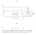
- FIG. 2 is a plan view of a cap plate shown in FIG. 1
- FIG. 3 is a cross-sectional view taken along the line I - I ' of FIG. 2
- FIG. 4 is a cross-sectional view illustrating another embodiment of a reinforcement unit shown in FIG. 3 .
- the secondary battery 100 includes an electrode assembly 110, a can 120 and a cap assembly 130.
- the electrode assembly 110 includes a first electrode plate 111 having a first active material coated on a surface of a first current collector, a second electrode plate 112 having a second active material coated on a surface of a second current collector, and a separator 113 interposed between the first electrode plate 111 and the second electrode plate 112 and electrically insulating the first electrode plate 111 and the second electrode plate 112 from each other.
- the electrode assembly 110 may include the first electrode plate 111, the second electrode plate 112 and the separator 113 wound in a jelly-roll configuration.
- the first electrode plate 111 may be made of an aluminum (Al) foil
- the second electrode plate 112 may be made of a copper (Cu) foil
- the separator 113 may be made of polyethylene (PE) or polypropylene (PP), but not limited thereto.
- a first electrode tab 114 is coupled to the first electrode plate 111 and protrudes to a top end of the electrode assembly 110
- a second electrode tab 115 is coupled to the second electrode plate 112 and protrudes to the top end of the electrode assembly 110.
- Insulation members 114a and 115a are attached to the first electrode tab 114 and the second electrode tab 115, thereby preventing short circuits from being caused between the first electrode tab 114 and the second electrode plate 112 and between the second electrode tab 115 and the first electrode plate 111.
- the can 120 is shaped of a substantially hexahedral box having a top opening to accommodate the electrode assembly 110.
- the can 120 is formed by deep drawing and is made of a light, ductile conductive metal such as aluminum or an aluminum alloy.
- the inner surface of the can 120 may be treated to be insulated from the electrode assembly 110.
- the can 120 may have a polarity, for example, a positive polarity.
- a safety vent 121 is formed on an outer surface of the can 120.
- the safety vent 121 is configured to be mechanically weaker than other parts around the safety vent 121. Therefore, the safety vent 121 is ruptured to release the internal gas generated when the internal gas is generated in the can 120 due to abnormality of the electrode assembly 110.
- the safety vent 121 is preferably formed on a long side surface of the can 120, which is easily swollen when the internal gas is generated in the can 120.
- the safety vent 121 having an "L" shape is exemplified.
- the safety vent 121 may have any shape as long as it can rupture the can 120 when the internal gas is generated in the can 120.
- the cap assembly 130 is coupled to the top end of the can 120.
- the cap assembly 130 includes an electrode terminal 140, a cap plate 150, an insulation plate 160, a terminal plate 170 and an insulation case 180.
- the electrode terminal 140 is coupled to the center of the cap plate 150.
- the electrode terminal 140 passes through the cap plate 150 to be electrically connected to the terminal plate 170.
- a gasket 141 is formed between the electrode terminal 140 and the cap plate 150, thereby insulating the electrode terminal 140 and the cap plate 150 from each other.
- the cap plate 150 seals the top end of the can 120 and is shaped of a substantially planar plate.
- a terminal hole 151 through which the electrode terminal 140 passes and to be coupled thereto, is formed at the center of the cap plate 150.
- an electrolyte injection hole 152 for injecting an electrolytic solution is formed in the cap plate 150. Once the electrolytic solution is formed, a plug (not shown) is installed in the electrolyte injection hole 152 to seal the electrolyte injection hole 152.
- a brittle part 154 is formed around the terminal hole 151. The brittle part 154 is configured to be mechanically weaker than other parts around the brittle part 154 and is in the form of a groove formed around the terminal hole 151.
- the brittle part 154 causes the secondary battery 100 to be deformed. That is to say, during the longitudinal compression test, the secondary battery 100 is folded about the brittle part 154.
- the electrode terminal 140 is mounted in the brittle part 154 together with the gasket 141.
- a reinforcement unit 153 is formed at one side of the cap plate 150. The reinforcement unit 153 will later be described in detail.
- the brittle part 154 acts as a deformable region in a central region of the cap plate 150, the deformable region being mechanically weaker than other regions of the cap plate 150.
- the deformable region could have other forms.
- An insulation plate 160 and a terminal plate 170 are sequentially formed under the cap plate 150.
- the insulation plate 160 insulates the cap plate 150 and the terminal plate 170 from each other.
- the terminal plate 170 is electrically connected to the electrode terminal 140.
- the terminal plate 170 is electrically connected to the second electrode tab 115.
- the insulation case 180 is made of a polymer resin having an insulating property, for example, polypropylene.
- the insulation case 180 is formed between the cap plate 150 and the electrode assembly 110.
- Holes 181 and 182 are formed in the insulation case 180 to allow the first electrode tab 114 and the second electrode tab 115 to pass therethrough.
- an electrolyte passing hole 183 is formed in the insulation case 180 to be located to correspond to the electrolyte injection hole 152.
- the reinforcement unit 153 is formed at one side of the cap plate 150 (e.g. a top or bottom surface) for the purpose of reinforcing strength of the cap plate 150.
- a force is applied to the center from both sides of the can 120 (e.g. the shorter lateral sides).
- the brittle part 154 which is weaker in strength than other peripheral parts, is formed at the center of the cap plate 150, the secondary battery 100 is bent about the brittle part 154, so that the terminal plate 170 and the can 120 are short-circuited to cause a current discharge, thereby preventing ignition and explosion of the secondary battery 100 due to over-heat of the electrode assembly 110.
- both sides of the cap plate 150 are first deformed due to the force applied from the both sides of the can 120.
- the secondary battery 100 may be put into a dangerous condition, such as ignition and explosion. Accordingly, in embodiments of the present invention, the strength of the both sides of the cap plate 150 is reinforced to cause a short circuit between the terminal plate 170 and the can 120 during the longitudinal compression test, thereby improving the safety of the secondary battery 100 by facilitating a current discharge.
- the reinforcement unit 153 is shaped of a substantially oval groove formed on the top surface of the cap plate 150.
- the reinforcement unit 153 may have various shapes, including a rectangle, a circle, a polygon, and so on.
- the reinforcement unit 153 is preferably shaped to fit and correspond to one end of the cap plate 150. In the illustrated embodiment, since the one end of the cap plate 150 is made to be round, the reinforcement unit 153 is also shaped to fit and correspond to the one end of the cap plate 150.
- the horizontal length L2 of the reinforcement unit 153 may be approximately 10 mm.
- the horizontal length L2 of the reinforcement unit 153 and the horizontal length L1 of the cap plate L1 may be in a range of 5% to 20%, preferably 20%.
- the length L2 of the reinforcement unit 153 is less than 5% of the length L1 of the cap plate 150, the strength of the cap plate 150 is not sufficiently improved, so that the end of the cap plate 150 is first deformed during the longitudinal compression test.
- the reinforcement unit 153 may overlap with the electrolyte injection hole 152 formed between the terminal hole 151 and the reinforcement unit 153, making it difficult to inject an electrolytic solution into the electrolyte injection hole 152.
- the ratio of a length of the reinforcement unit 153 to a length of the cap plate may be from 1:2 to 1:20.
- the reinforcement unit 153 is spaced a predetermined distance apart from the end of the cap plate 150.
- a distance L3 ranging from the end of the cap plate 150 to a starting point of the end of the reinforcement unit 153 is approximately 10% of the horizontal length L1 of the cap plate 150.
- a distance L3 ranging from the end of the cap plate 150 to a starting point of the end of the reinforcement unit 153 is approximately 5 to 15% of the horizontal length L1 of the cap plate 150.
- the width W2 of the reinforcement unit 153 may be in a range of 5% to 38%.
- the width W2 of the reinforcement unit 153 is less than 5% of the width W1 of the cap plate 150, the strength of the cap plate 150 is not sufficiently improved, so that the end of the cap plate 150 is first deformed during the longitudinal compression test.
- the width W2 of the reinforcement unit 153 is greater than 38% of the width W1 of the cap plate 150, it is difficult to tightly fix the cap plate 150 to the can 120.
- the reinforcement unit 153 is formed as a groove formed on the top surface of the cap plate 150.
- the thickness T2 of the groove may be approximately 0.4 mm.
- the reinforcement unit 153 is formed at one side of the cap plate 150, thereby preventing the end of the cap plate 150 from being first deformed during a longitudinal compression test. Therefore, the secondary battery 100 according to this embodiment of the present invention causes a short circuit between the terminal plate 170 and the can 120 during the longitudinal compression test to facilitate a current discharge, thereby improving the safety of the secondary battery 100.
- FIG. 4 is a cross-sectional view illustrating another embodiment of the reinforcement unit shown in FIG. 3 .
- the cap plate 250 includes a centrally formed terminal hole 151, an electrolyte injection hole 152 through which an electrolytic solution is injected, a brittle part 154 formed around the terminal hole 151, and a reinforcement unit 253 formed at one side of the cap plate 150.
- the reinforcement unit 253 is formed at one side of the cap plate 250 for the purpose of increasing the strength of the cap plate 250.
- the reinforcement unit 253 includes a groove 253a formed on a top surface of the cap plate 250 and a protrusion part 253b formed on a bottom surface of the cap plate 250. That is to say, the reinforcement unit 253 further includes the protrusion part 253b protruding to the bottom surface of the cap plate 250, compared to the reinforcement unit 153 shown in FIG. 3 .
- the protrusion part 253b may protrude to the bottom surface of the cap plate 250 as much as a thickness T2 of the groove 253a.
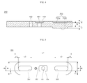
- FIG. 5 is a cross-sectional view illustrating a cap plate having a reinforcement unit according to still another embodiment of the present invention and FIG. 6 is a cross-sectional view taken along the line II-II' of FIG. 5 .
- the cap plate 350 includes a centrally formed terminal hole 151, an electrolyte injection hole 152 through which an electrolytic solution is injected, a brittle part 154 formed around the terminal hole 151, and reinforcement units 353 and 354 formed at both sides of the cap plate 350. That is to say, the reinforcement units 353 and 354 of this embodiment are different from the reinforcement unit 153 shown in FIG. 3 in that they are formed at both sides of the cap plate 350.
- the reinforcement units 353 and 354 are preferably formed at both sides of the cap plate 350.
- the reinforcement units 353 and 354 include a first reinforcement unit 353 formed at one side of the cap plate 350 and a second reinforcement unit 354 formed at the other side of the cap plate 350.
- the first reinforcement unit 353 and the second reinforcement unit 354 are groves formed on a top surface of the cap plate 350, the grooves having substantially oval shapes. Since the first reinforcement unit 353 is substantially the same as the reinforcement unit 153 shown in FIG. 3 in view of configuration, a detailed description thereof will not be given.
- the second reinforcement unit 354 is formed to have the same configuration with the first reinforcement unit 353.
- the second reinforcement unit 354 is spaced apart from the other end of the cap plate 350.
- a distance L3 between the cap plate 350 and the second reinforcement unit 354 is 10% of the horizontal length L1 of the cap plate 350.
- the second reinforcement unit 354 is shaped of a groove formed on a stop surface of the cap plate 350.
- the ratio of a length of the second reinforcement unit 354 to a length of the cap plate may be from 1:2 to 1:20.
- FIG. 7 is a cross-sectional view illustrating a cap plate having a reinforcement unit according to still another embodiment of the present invention.
- the cap plate 450 includes a centrally formed terminal hole 151, an electrolyte injection hole 152 through which an electrolytic solution is injected, a brittle part 154 formed around the terminal hole 151, and reinforcement units 453 and 454 formed at both sides of the cap plate 450.
- the reinforcement units 453 and 454 include a first reinforcement unit 453 formed at one side of the cap plate 450 and a second reinforcement unit 454 formed at the other side of the cap plate 450.
- the first reinforcement unit 453 includes a groove 453a formed on a top surface of the cap plate 450 and a protrusion part 453b formed on a bottom surface of the cap plate 450.
- the second reinforcement unit 454 includes a groove 454a formed on a top surface of the cap plate 450 and a protrusion part 454b formed on a bottom surface of the cap plate 450. That is to say, the reinforcement units 453 and 454 are different from the reinforcement units 353 and 354 shown in FIG.
- FIG. 8 is a plan view illustrating an appearance of the secondary battery during a longitudinal compression test.
- the secondary battery 100 undergoes a current discharge while it is bent about brittle part 154 formed at the center of the cap plate 350 to cause a short circuit between a terminal plate 170 and the can 120. Therefore, it is possible to prevent ignition or explosion from occurring to the secondary battery 100 due to over-heating of an electrode assembly 110.
- the brittle part 154 is formed at the center of the cap plate 350, the can 120 is bent about the center of the cap plate 350 during the longitudinal compression test.
- the reinforcement units 353 and 354 are formed at both sides of the cap plate 350, thereby preventing the both sides of the cap plate 350 from being deformed due to the force applied to the both sides of the cap plate 350 during the longitudinal compression test. Therefore, the secondary battery 100 according to this embodiment of the present invention causes a short circuit between the terminal plate 170 and the can 120 during the longitudinal compression test to facilitate a current discharge by reinforcing the strength at the both sides of the cap plate 350, thereby improving the safety of the secondary battery 100.
- FIG. 9 is a cross-sectional view illustrating a cap plate having a reinforcement unit according to still another embodiment of the present invention.
- the cap plate 550 includes a centrally formed terminal hole 151, an electrolyte injection hole 152 through which an electrolytic solution is injected, a brittle part 154 formed around the terminal hole 151, and a reinforcement unit 553 formed at one side of the cap plate 550.
- the reinforcement unit 553 comprises a protrusion part formed on a bottom surface of the cap plate 550, the protrusion part having thickness T3.
- a secondary battery comprising: an electrode assembly; a can arranged to accommodate the electrode assembly; a cap plate coupled to a one end of the can and arranged to seal the can; wherein the cap plate comprises a deformable region in a central region of the cap plate, the deformable region being mechanically weaker than other regions of the cap plate; wherein the cap plate further comprises a reinforcement unit formed on at least one side region of the cap plate.
- the deformable region may comprise a groove in the cap plate.
- the cap plate may comprises a terminal hole located in the central region of the cap plate.
- the deformable region comprises a groove in the cap plate located at least partially around the terminal hole.
- the reinforcement unit may comprise a groove formed in a surface of the cap plate. In some embodiments, the reinforcement unit comprises a groove formed in an outer surface of the cap plate.
- the reinforcement unit may comprise a protrusion formed on a surface of the cap plate. In some embodiments, the reinforcement unit comprises a protrusion formed on an inner surface of the cap plate.
- the reinforcement unit may comprise a groove formed in one surface of the cap plate and a protrusion formed on an opposite surface of the cap plate.
- the reinforcement unit (comprises a groove formed in an outer surface of the cap plate and a protrusion formed on an inner surface of the cap plate.
- the groove is located at a corresponding position to the protrusion, and a depth of the groove and is the same as a thickness of the protrusion.
- a safety vent is formed on a long side surface of the can so as to be ruptured when the gas is generated in the can due to an abnormality of the electrode assembly.
- the reinforcement unit does not act as a safety vent.
Landscapes
- Chemical & Material Sciences (AREA)
- Chemical Kinetics & Catalysis (AREA)
- Electrochemistry (AREA)
- General Chemical & Material Sciences (AREA)
- Engineering & Computer Science (AREA)
- Manufacturing & Machinery (AREA)
- Sealing Battery Cases Or Jackets (AREA)
- Gas Exhaust Devices For Batteries (AREA)
Abstract
Description
- Aspects of the present invention relate to a secondary battery.
- In general, during a longitudinal compression test of a secondary battery, a force is applied to the center of a can from both sides of the can. Here, since the secondary battery undergoes a current discharge while it is bent about the center of the can to cause a short circuit between a terminal plate and the can, ignition or explosion may occur to the secondary battery due to over-heating of an electrode assembly. However, during the longitudinal compression test, due to the force applied from both sides of the can, both sides of the cap plate are deformed earlier than other portions of the can before the short circuit between the terminal plate and the can occurs. Therefore, since the short circuit between the terminal plate and the can is not properly caused, there is a risk of ignition and explosion of the secondary battery.
- Aspects of the present invention provide a secondary battery, which can improve safety during a longitudinal compression test by reinforcing strength of a cap plate.
- In accordance with one aspect of the present invention, there is provided a secondary battery including an electrode assembly, a can accommodating the electrode assembly, and cap plate coupled to a top portion of the can and sealing the can, wherein a reinforcement unit is formed on at least one side of the cap plate.
- The reinforcement unit may be a groove formed on a top surface of the cap plate.
- A ratio of a horizontal length of the reinforcement unit to a horizontal length of the cap plate may be 1:5.
- A horizontal length of the reinforcement unit may be 5% to 20% of a horizontal length of the cap plate.
- A ratio of a width of the reinforcement unit to a width of the cap plate may be 1:2.64.
A width of the reinforcement unit may be 5% to 38% of a width of the cap plate. - A ratio of a thickness of the reinforcement unit to a thickness of the cap plate may be 1:2.5.
- The reinforcement unit may be spaced apart from an end of the cap plate, and a distance between the cap plate and the reinforcement unit may be 10% of the horizontal length of the cap plate.
- The reinforcement unit may further include a protrusion part protruding to a bottom surface of the cap plate.
- The protrusion part may be formed to correspond to the groove, and the protrusion part and the groove may have the same thickness.
- The secondary battery of claim 1, wherein the reinforcement unit includes a first reinforcement unit formed on one side of the cap plate and a second reinforcement unit formed on the other side of the cap plate.
- The first reinforcement unit and the second reinforcement unit may be formed to be symmetrical to each other about the center of the cap plate.
- The first reinforcement unit and the second reinforcement unit may be grooves formed on a top surface of the cap plate.
- A ratio of a horizontal length of the first reinforcement unit to a horizontal length of the cap plate may be 1:5 and a ratio of a horizontal length of the second reinforcement unit to a horizontal length of the cap plate is 1:5.
- A ratio of a width of the first reinforcement unit to a width of the cap plate may be 1:2.64 and a ratio of a width of the second reinforcement unit to the width of the cap plate may be 1:2.64.
- A ratio of a thickness of the first reinforcement unit to a thickness of the cap plate may be 1:2.5 and a ratio of a thickness of the second reinforcement unit to the thickness of the cap plate may be 1:2.5.
Each of the first reinforcement unit and the second reinforcement unit may further include a protrusion part protruding to a bottom surface of the cap plate, and the protrusion part and the groove may have the same thickness. - A safety vent may be formed on a long side surface of the can so as to be ruptured when the gas is generated in the can due to abnormality of the electrode assembly.
- A brittle part having a relatively small strength may be formed on a central region of the cap plate.
- The reinforcement unit may reinforce the strength of the cap plate by preventing at least one side of the cap plate from being deformed due to a force applied from both sides of the can during a longitudinal compression test.
- As described above, in the secondary battery according to the embodiment of the present invention, a reinforcement unit is formed on one side of the cap plate, thereby preventing an end of the cap plate from being deformed earlier than other portions of the cap plate during a longitudinal compression test. Accordingly, in the secondary battery according to the embodiment of the present invention, a short circuit between a terminal plate and a can is caused during the longitudinal compression test to facilitate a current discharge, thereby improving the safety of the secondary battery.
- According to an aspect of the invention, there is provided a secondary battery as set out in claim 1. Preferred features of this aspect are set out in claims 2 to 15.
- Additional aspects and/or advantages of the invention will be set forth in part in the description which follows and, in part, will be obvious from the description, or may be learned by practice of the invention.
- The objects, features and advantages of the present invention will be more apparent from the following detailed description in conjunction with the accompanying drawings, in which:
-
FIG. 1 is an exploded perspective view of a secondary battery according to an embodiment of the present invention; -
FIG. 2 is a plan view of a cap plate shown inFIG. 1 ; -
FIG. 3 is a cross-sectional view taken along the line I - I ' ofFIG. 2 ; -
FIG. 4 is a cross-sectional view illustrating another embodiment of a reinforcement unit shown inFIG. 3 ; -
FIG. 5 is a cross-sectional view illustrating a cap plate having a reinforcement unit according to still another embodiment of the present invention; -
FIG. 6 is a cross-sectional view taken along the line II - II' ofFIG. 5 ; -
FIG. 7 is a cross-sectional view illustrating a cap plate having a reinforcement unit according to still another embodiment of the present invention; -
FIG. 8 is a plan view illustrating an appearance of the secondary battery during a longitudinal compression test; and -
FIG. 9 is a cross-sectional view illustrating a cap plate having a reinforcement unit according to still another embodiment of the present invention. -
FIG. 1 is an exploded perspective view of a secondary battery according to an embodiment of the present invention,FIG. 2 is a plan view of a cap plate shown inFIG. 1 ,FIG. 3 is a cross-sectional view taken along the line I - I ' ofFIG. 2 , andFIG. 4 is a cross-sectional view illustrating another embodiment of a reinforcement unit shown inFIG. 3 . - Referring to
FIG. 1 , thesecondary battery 100 according to this embodiment of the present invention includes anelectrode assembly 110, acan 120 and acap assembly 130. - The
electrode assembly 110 includes afirst electrode plate 111 having a first active material coated on a surface of a first current collector, asecond electrode plate 112 having a second active material coated on a surface of a second current collector, and aseparator 113 interposed between thefirst electrode plate 111 and thesecond electrode plate 112 and electrically insulating thefirst electrode plate 111 and thesecond electrode plate 112 from each other. Theelectrode assembly 110 may include thefirst electrode plate 111, thesecond electrode plate 112 and theseparator 113 wound in a jelly-roll configuration. Here, thefirst electrode plate 111 may be made of an aluminum (Al) foil, thesecond electrode plate 112 may be made of a copper (Cu) foil, and theseparator 113 may be made of polyethylene (PE) or polypropylene (PP), but not limited thereto. In addition, afirst electrode tab 114 is coupled to thefirst electrode plate 111 and protrudes to a top end of theelectrode assembly 110, and asecond electrode tab 115 is coupled to thesecond electrode plate 112 and protrudes to the top end of theelectrode assembly 110.Insulation members first electrode tab 114 and thesecond electrode tab 115, thereby preventing short circuits from being caused between thefirst electrode tab 114 and thesecond electrode plate 112 and between thesecond electrode tab 115 and thefirst electrode plate 111. - The
can 120 is shaped of a substantially hexahedral box having a top opening to accommodate theelectrode assembly 110. In addition, thecan 120 is formed by deep drawing and is made of a light, ductile conductive metal such as aluminum or an aluminum alloy. Further, the inner surface of thecan 120 may be treated to be insulated from theelectrode assembly 110. Here, thecan 120 may have a polarity, for example, a positive polarity. In addition, asafety vent 121 is formed on an outer surface of thecan 120. Thesafety vent 121 is configured to be mechanically weaker than other parts around thesafety vent 121. Therefore, thesafety vent 121 is ruptured to release the internal gas generated when the internal gas is generated in thecan 120 due to abnormality of theelectrode assembly 110. In addition, thesafety vent 121 is preferably formed on a long side surface of thecan 120, which is easily swollen when the internal gas is generated in thecan 120. In the illustrated embodiment, thesafety vent 121 having an "L" shape is exemplified. However, thesafety vent 121 may have any shape as long as it can rupture thecan 120 when the internal gas is generated in thecan 120. - The
cap assembly 130 is coupled to the top end of thecan 120. Thecap assembly 130 includes anelectrode terminal 140, acap plate 150, aninsulation plate 160, aterminal plate 170 and aninsulation case 180. - The
electrode terminal 140 is coupled to the center of thecap plate 150. Theelectrode terminal 140 passes through thecap plate 150 to be electrically connected to theterminal plate 170. Here, agasket 141 is formed between theelectrode terminal 140 and thecap plate 150, thereby insulating theelectrode terminal 140 and thecap plate 150 from each other. - The
cap plate 150 seals the top end of thecan 120 and is shaped of a substantially planar plate. Aterminal hole 151, through which theelectrode terminal 140 passes and to be coupled thereto, is formed at the center of thecap plate 150. In addition, anelectrolyte injection hole 152 for injecting an electrolytic solution is formed in thecap plate 150. Once the electrolytic solution is formed, a plug (not shown) is installed in theelectrolyte injection hole 152 to seal theelectrolyte injection hole 152. In addition, abrittle part 154 is formed around theterminal hole 151. Thebrittle part 154 is configured to be mechanically weaker than other parts around thebrittle part 154 and is in the form of a groove formed around theterminal hole 151. During a longitudinal compression test of thesecondary battery 100, thebrittle part 154 causes thesecondary battery 100 to be deformed. That is to say, during the longitudinal compression test, thesecondary battery 100 is folded about thebrittle part 154. In addition, theelectrode terminal 140 is mounted in thebrittle part 154 together with thegasket 141. In addition, areinforcement unit 153 is formed at one side of thecap plate 150. Thereinforcement unit 153 will later be described in detail. - Hence, the
brittle part 154 acts as a deformable region in a central region of thecap plate 150, the deformable region being mechanically weaker than other regions of thecap plate 150. In other embodiments, the deformable region could have other forms. - An
insulation plate 160 and aterminal plate 170 are sequentially formed under thecap plate 150. Theinsulation plate 160 insulates thecap plate 150 and theterminal plate 170 from each other. Theterminal plate 170 is electrically connected to theelectrode terminal 140. In addition, theterminal plate 170 is electrically connected to thesecond electrode tab 115. - The
insulation case 180 is made of a polymer resin having an insulating property, for example, polypropylene. Theinsulation case 180 is formed between thecap plate 150 and theelectrode assembly 110.Holes insulation case 180 to allow thefirst electrode tab 114 and thesecond electrode tab 115 to pass therethrough. In addition, anelectrolyte passing hole 183 is formed in theinsulation case 180 to be located to correspond to theelectrolyte injection hole 152. - Next, a reinforcement unit formed in the cap plate will be described in detail.
- Referring to
FIGS. 2 and 3 , thereinforcement unit 153 is formed at one side of the cap plate 150 (e.g. a top or bottom surface) for the purpose of reinforcing strength of thecap plate 150. - In general, during the longitudinal compression test of the
secondary battery 100, a force is applied to the center from both sides of the can 120 (e.g. the shorter lateral sides). Here, since thebrittle part 154, which is weaker in strength than other peripheral parts, is formed at the center of thecap plate 150, thesecondary battery 100 is bent about thebrittle part 154, so that theterminal plate 170 and thecan 120 are short-circuited to cause a current discharge, thereby preventing ignition and explosion of thesecondary battery 100 due to over-heat of theelectrode assembly 110. However, during the longitudinal compression test of thesecondary battery 100, before theterminal plate 170 and thecan 120 are short-circuited, both sides of thecap plate 150 are first deformed due to the force applied from the both sides of thecan 120. Therefore, since the short circuit between theterminal plate 170 and thecan 120 is not properly caused, thesecondary battery 100 may be put into a dangerous condition, such as ignition and explosion. Accordingly, in embodiments of the present invention, the strength of the both sides of thecap plate 150 is reinforced to cause a short circuit between theterminal plate 170 and thecan 120 during the longitudinal compression test, thereby improving the safety of thesecondary battery 100 by facilitating a current discharge. - In this embodiment, the
reinforcement unit 153 is shaped of a substantially oval groove formed on the top surface of thecap plate 150. In other embodiments, thereinforcement unit 153 may have various shapes, including a rectangle, a circle, a polygon, and so on. In some embodiments, thereinforcement unit 153 is preferably shaped to fit and correspond to one end of thecap plate 150. In the illustrated embodiment, since the one end of thecap plate 150 is made to be round, thereinforcement unit 153 is also shaped to fit and correspond to the one end of thecap plate 150. - In addition, in this embodiment, a ratio of a horizontal length L2 of the
reinforcement unit 153 to a horizontal length L1 of thecap plate 150 is approximately 1:5 (that is, L2:L1=1:5). For example, assuming that the horizontal length L1 of thecap plate 150 is 50 mm, the horizontal length L2 of thereinforcement unit 153 may be approximately 10 mm. In addition, the horizontal length L2 of thereinforcement unit 153 and the horizontal length L1 of the cap plate L1 may be in a range of 5% to 20%, preferably 20%. Here, if the length L2 of thereinforcement unit 153 is less than 5% of the length L1 of thecap plate 150, the strength of thecap plate 150 is not sufficiently improved, so that the end of thecap plate 150 is first deformed during the longitudinal compression test. In addition, if the length L2 of thereinforcement unit 153 is greater than 20% of the length L1 of thecap plate 150, thereinforcement unit 153 may overlap with theelectrolyte injection hole 152 formed between theterminal hole 151 and thereinforcement unit 153, making it difficult to inject an electrolytic solution into theelectrolyte injection hole 152. - In other embodiments, the ratio of a length of the
reinforcement unit 153 to a length of the cap plate may be from 1:2 to 1:20. - In addition, the
reinforcement unit 153 is spaced a predetermined distance apart from the end of thecap plate 150. In detail, a distance L3 ranging from the end of thecap plate 150 to a starting point of the end of thereinforcement unit 153 is approximately 10% of the horizontal length L1 of thecap plate 150. In other embodiments, a distance L3 ranging from the end of thecap plate 150 to a starting point of the end of thereinforcement unit 153 is approximately 5 to 15% of the horizontal length L1 of thecap plate 150. - In addition, a ratio of a width W2 of the
reinforcement unit 153 to a width W1 of thecap plate 150 may be 1:2 to 1:20 (that is, W2:W1=1:2 to 1:20). In other embodiments, a ratio of a width W2 of thereinforcement unit 153 to a width W1 of thecap plate 150 may be 1:2.64 (that is, W2:W1=1:2.64). For example, assuming that the width W1 of thecap plate 150 is 4.22 mm, the width W2 of thereinforcement unit 153 may be approximately 1.6 mm. In addition, the width W2 of thereinforcement unit 153 may be in a range of 5% to 50%. In other embodiments, the width W2 of thereinforcement unit 153 may be in a range of 5% to 38%. Here, if the width W2 of thereinforcement unit 153 is less than 5% of the width W1 of thecap plate 150, the strength of thecap plate 150 is not sufficiently improved, so that the end of thecap plate 150 is first deformed during the longitudinal compression test. In addition, if the width W2 of thereinforcement unit 153 is greater than 38% of the width W1 of thecap plate 150, it is difficult to tightly fix thecap plate 150 to thecan 120. - Further, the
reinforcement unit 153 is formed as a groove formed on the top surface of thecap plate 150. Meanwhile, a ratio of a thickness T2 of the groove to a thickness T1 of thecap plate 150 may be 1:1.25 to 1:10 (that is, T2:T1=1:1.25 to 1:10). In other embodiments, a ratio of a thickness T2 of the groove to a thickness T1 of thecap plate 150 may be 1:2.5 (that is, T2:T1=1:2.5). For example, assuming that the thickness T1 of the cap plate is 1 mm, the thickness T2 of the groove may be approximately 0.4 mm. As described above, in thesecondary battery 100 according to this embodiment of the present invention, thereinforcement unit 153 is formed at one side of thecap plate 150, thereby preventing the end of thecap plate 150 from being first deformed during a longitudinal compression test. Therefore, thesecondary battery 100 according to this embodiment of the present invention causes a short circuit between theterminal plate 170 and thecan 120 during the longitudinal compression test to facilitate a current discharge, thereby improving the safety of thesecondary battery 100. -
FIG. 4 is a cross-sectional view illustrating another embodiment of the reinforcement unit shown inFIG. 3 . - Referring to
FIG. 4 , thecap plate 250 includes a centrally formedterminal hole 151, anelectrolyte injection hole 152 through which an electrolytic solution is injected, abrittle part 154 formed around theterminal hole 151, and areinforcement unit 253 formed at one side of thecap plate 150. - The
reinforcement unit 253 is formed at one side of thecap plate 250 for the purpose of increasing the strength of thecap plate 250. Thereinforcement unit 253 includes agroove 253a formed on a top surface of thecap plate 250 and aprotrusion part 253b formed on a bottom surface of thecap plate 250. That is to say, thereinforcement unit 253 further includes theprotrusion part 253b protruding to the bottom surface of thecap plate 250, compared to thereinforcement unit 153 shown inFIG. 3 . Theprotrusion part 253b may protrude to the bottom surface of thecap plate 250 as much as a thickness T2 of thegroove 253a. That is to say, the thickness T2 of thegroove 253a may be equal to a thickness T3 of theprotrusion part 253b (that is, T2=T3). That is to say, thegroove 253a is formed on the top surface of thecap plate 250 and theprotrusion part 253b is formed on the bottom surface of thecap plate 250 by pressing the top surface of thecap plate 250 using a pressing device in the course of forming thereinforcement unit 253. -
FIG. 5 is a cross-sectional view illustrating a cap plate having a reinforcement unit according to still another embodiment of the present invention andFIG. 6 is a cross-sectional view taken along the line II-II' ofFIG. 5 . - Referring to
FIGS. 5 and6 , thecap plate 350 includes a centrally formedterminal hole 151, anelectrolyte injection hole 152 through which an electrolytic solution is injected, abrittle part 154 formed around theterminal hole 151, andreinforcement units cap plate 350. That is to say, thereinforcement units reinforcement unit 153 shown inFIG. 3 in that they are formed at both sides of thecap plate 350. Here, since a force is applied from both sides of acan 120 during a longitudinal compression test, thereinforcement units cap plate 350. - In this embodiment, the
reinforcement units first reinforcement unit 353 formed at one side of thecap plate 350 and asecond reinforcement unit 354 formed at the other side of thecap plate 350. Thefirst reinforcement unit 353 and thesecond reinforcement unit 354 are groves formed on a top surface of thecap plate 350, the grooves having substantially oval shapes. Since thefirst reinforcement unit 353 is substantially the same as thereinforcement unit 153 shown inFIG. 3 in view of configuration, a detailed description thereof will not be given. - The
second reinforcement unit 354 is formed to have the same configuration with thefirst reinforcement unit 353. In addition, thefirst reinforcement unit 353 and thesecond reinforcement unit 354 are positioned symmetrically with respect to the center of thecap plate 350. Therefore, length, width and thickness ratios of thesecond reinforcement unit 354 and thecap plate 350 are the same as described above. That is to say, a ratio of a horizontal length L2 of thesecond reinforcement unit 354 to a horizontal length L1 of thecap plate 350 is approximately 1:5 (that is, L2:L1=1:5). In addition, the horizontal length L2 of thesecond reinforcement unit 354 may be in a range of approximately 5% to 20% (that is, L2:L1=1:5), preferably 20%. In addition, thesecond reinforcement unit 354 is spaced apart from the other end of thecap plate 350. - In detail, a distance L3 between the
cap plate 350 and thesecond reinforcement unit 354 is 10% of the horizontal length L1 of thecap plate 350. In addition, a ratio of a width W2 of the second reinforcement unit to the width W1 of thecap plate 350 is approximately 1:2.64 (that is, W2:W1=1:2.64). In other embodiments, a ratio of a width W2 of the second reinforcement unit to a width W1 of thecap plate 150 may be 1:2 to 1:20 (that is, W2:W1=1:2 to 1:20). Further, thesecond reinforcement unit 354 is shaped of a groove formed on a stop surface of thecap plate 350. A ratio of a thickness T2 of the groove to a thickness T1 of thecap plate 350 is approximately 1:2.5 (that is, T2:T1=1.2.5). In other embodiments, a ratio of a thickness T2 of the groove to a thickness T1 of thecap plate 150 may be1:1.25 to 1:10 (that is, T2:T1=1:1.25 to 1:10). - In some embodiments, the ratio of a length of the
second reinforcement unit 354 to a length of the cap plate may be from 1:2 to 1:20. -
FIG. 7 is a cross-sectional view illustrating a cap plate having a reinforcement unit according to still another embodiment of the present invention. - Referring to
FIG. 7 , thecap plate 450 includes a centrally formedterminal hole 151, anelectrolyte injection hole 152 through which an electrolytic solution is injected, abrittle part 154 formed around theterminal hole 151, andreinforcement units cap plate 450. - In this embodiment, the
reinforcement units first reinforcement unit 453 formed at one side of thecap plate 450 and asecond reinforcement unit 454 formed at the other side of thecap plate 450. In addition, thefirst reinforcement unit 453 includes agroove 453a formed on a top surface of thecap plate 450 and aprotrusion part 453b formed on a bottom surface of thecap plate 450. Thesecond reinforcement unit 454 includes agroove 454a formed on a top surface of thecap plate 450 and aprotrusion part 454b formed on a bottom surface of thecap plate 450. That is to say, thereinforcement units reinforcement units FIG. 6 in that they further include theprotrusion parts cap plate 450. That is to say, a thickness T3 of theprotrusion part 453 may be equal to a thickness T2 of the groove formed on the top surface of the cap plate 450 (that is, T3=T2). -
FIG. 8 is a plan view illustrating an appearance of the secondary battery during a longitudinal compression test. - As shown in
FIG. 8 , if a force is applied to the center of a can 120 from both sides of thecan 120 during a longitudinal compression test of asecondary battery 100, thesecondary battery 100 undergoes a current discharge while it is bent aboutbrittle part 154 formed at the center of thecap plate 350 to cause a short circuit between aterminal plate 170 and thecan 120. Therefore, it is possible to prevent ignition or explosion from occurring to thesecondary battery 100 due to over-heating of anelectrode assembly 110. Here, since thebrittle part 154 is formed at the center of thecap plate 350, thecan 120 is bent about the center of thecap plate 350 during the longitudinal compression test. In addition, in thesecondary battery 100 according to this embodiment of the present invention, thereinforcement units cap plate 350, thereby preventing the both sides of thecap plate 350 from being deformed due to the force applied to the both sides of thecap plate 350 during the longitudinal compression test. Therefore, thesecondary battery 100 according to this embodiment of the present invention causes a short circuit between theterminal plate 170 and thecan 120 during the longitudinal compression test to facilitate a current discharge by reinforcing the strength at the both sides of thecap plate 350, thereby improving the safety of thesecondary battery 100. -
FIG. 9 is a cross-sectional view illustrating a cap plate having a reinforcement unit according to still another embodiment of the present invention. - Referring to
FIG. 9 , thecap plate 550 includes a centrally formedterminal hole 151, anelectrolyte injection hole 152 through which an electrolytic solution is injected, abrittle part 154 formed around theterminal hole 151, and areinforcement unit 553 formed at one side of thecap plate 550. - In this embodiment, the
reinforcement unit 553 comprises a protrusion part formed on a bottom surface of thecap plate 550, the protrusion part having thickness T3. - As discussed, embodiments of the invention provide a secondary battery comprising: an electrode assembly; a can arranged to accommodate the electrode assembly; a cap plate coupled to a one end of the can and arranged to seal the can; wherein the cap plate comprises a deformable region in a central region of the cap plate, the deformable region being mechanically weaker than other regions of the cap plate; wherein the cap plate further comprises a reinforcement unit formed on at least one side region of the cap plate.
- The deformable region may comprise a groove in the cap plate. In some embodiments, the cap plate may comprises a terminal hole located in the central region of the cap plate. In some embodiments, the deformable region comprises a groove in the cap plate located at least partially around the terminal hole.
- The reinforcement unit may comprise a groove formed in a surface of the cap plate. In some embodiments, the reinforcement unit comprises a groove formed in an outer surface of the cap plate.
- The reinforcement unit may comprise a protrusion formed on a surface of the cap plate. In some embodiments, the reinforcement unit comprises a protrusion formed on an inner surface of the cap plate.
- The reinforcement unit may comprise a groove formed in one surface of the cap plate and a protrusion formed on an opposite surface of the cap plate. In some embodiments, the reinforcement unit (comprises a groove formed in an outer surface of the cap plate and a protrusion formed on an inner surface of the cap plate. In some embodiments, the groove is located at a corresponding position to the protrusion, and a depth of the groove and is the same as a thickness of the protrusion.
- In some embodiments, a safety vent is formed on a long side surface of the can so as to be ruptured when the gas is generated in the can due to an abnormality of the electrode assembly. The reinforcement unit does not act as a safety vent.
- Although the secondary batteries according to exemplary embodiments of the present invention have been described in detail hereinabove, it should be understood that many variations and modifications of the basic inventive concept herein described, which may appear to those skilled in the art, will still fall within the scope of the exemplary embodiments of the present invention as defined by the appended claims.
Claims (15)
- A secondary battery comprising:an electrode assembly (110);a can (120) arranged to accommodate the electrode assembly (110);a cap plate (150) coupled to a one end of the can (120) and arranged to seal the can (120);wherein the cap plate (150) comprises a deformable region in a central region of the cap plate (150), the deformable region being mechanically weaker than other regions of the cap plate (150);wherein the cap plate (150) further comprises a reinforcement unit (153, 253, 353, 354, 453, 454) formed on at least one side region of the cap plate (150).
- The secondary battery according to claim 1, wherein the deformable region comprises a groove (154) in the cap plate (150).
- The secondary battery according to claim 1 or 2, wherein the cap plate (150) comprises a terminal hole (151) located in the central region of the cap plate (150);
optionally wherein the deformable region comprises a groove (154) in the cap plate (150) located at least partially around the terminal hole (151). - The secondary battery of any one of claims 1 to 3, wherein the reinforcement unit (153, 253, 353, 354, 453, 454) comprises a groove formed in a surface of the cap plate (150);
optionally wherein the reinforcement unit (153, 253, 353, 354, 453, 454) comprises a groove formed in an outer surface of the cap plate (150). - The secondary battery of any one of claims 1 to 3, wherein the reinforcement unit (454) comprises a protrusion (454b) formed on a surface of the cap plate (150);
optionally wherein the reinforcement unit (454b) comprises a protrusion formed on an inner surface of the cap plate (150). - The secondary battery of any one of claims 1 to 3, wherein the reinforcement unit (153, 253, 353, 354, 453, 454) comprises a groove formed in one surface of the cap plate (150) and a protrusion (153, 253, 353, 354, 453, 454) formed on an opposite surface of the cap plate (150);
optionally wherein the reinforcement unit (153, 253, 353, 354, 453, 454) comprises a groove formed in an outer surface of the cap plate (150) and a protrusion formed on an inner surface of the cap plate (150);
further optionally wherein the groove is located at a corresponding position to the protrusion, and a depth of the groove is the same as a thickness of the protrusion. - The secondary battery of any one of claims 1 to 6, wherein a ratio of a length of the reinforcement unit (153, 253, 353, 354, 453, 454) to a length of the cap plate is from1:2 to 1:20;
optionally wherein a ratio of a length of the reinforcement unit (153, 253, 353, 354, 453, 454) to a length of the cap plate is 1:5. - The secondary battery of any one of claims 1 to 7, wherein a length of the reinforcement unit is from 5% to 50% of a length of the cap plate;
optionally wherein a length of the reinforcement unit is from 5% to 20% of a length of the cap plate. - The secondary battery of any one of claims 1 to 8, wherein a ratio of a width of the reinforcement unit (153, 253, 353, 354, 453, 454) to a width of the cap plate (150) is from 1:2 to 1:20;
optionally wherein a ratio of a width of the reinforcement unit (153, 253, 353, 354, 453, 454) to a width of the cap plate (150) is 1:2.64. - The secondary battery of any one of claims 1 to 9, wherein a width of the reinforcement unit (153, 253, 353, 354, 453, 454) is from 5% to 50% of a width of the cap plate (150);
optionally wherein a width of the reinforcement unit (153, 253, 353, 354, 453, 454) is from 5% to 38% of a width of the cap plate (150). - The secondary battery of any one of claims 1 to 10, wherein a ratio of a thickness of the reinforcement unit (153, 253, 353, 354, 453, 454) to a thickness of the cap plate (150) is from 1:1.25 to 1:10;
optionally wherein a ratio of a thickness of the reinforcement unit (153, 253, 353,354,453,454) to a thickness of the cap plate (150) is 1:2.5. - The secondary battery of any one of claims 1 to 11, wherein the reinforcement unit (153, 253, 353, 354, 453, 454) is spaced apart from an end of the cap plate (150), and a distance between the cap plate (150) and the reinforcement unit (153, 2533 353, 354, 453, 454) is from 5% to 15% of the length of the cap plate (150);
optionally wherein a distance between the cap plate (150) and the reinforcement unit (153, 253, 353, 354, 453, 454) is 10% of the length of the cap plate (150). - The secondary battery of any one of claims 1 to 12, comprises two said reinforcement units (353, 354, 453, 454), the two said reinforcement units comprising a first reinforcement unit (353, 453) formed on one side region of the cap plate (150) and a second reinforcement unit (354, 454) formed on an opposite side region of the cap plate (150).
- The secondary battery of claim 13, wherein the first reinforcement unit and the second reinforcement unit (353, 354, 453, 454) are arranged symmetrically about a central region of the cap plate (150).
- The secondary battery of any one of claims 1 to 14, wherein a safety vent (121) is formed on a long side surface of the can (150) so as to be ruptured when the gas is generated in the can due to an abnormality of the electrode assembly (110).
Applications Claiming Priority (1)
| Application Number | Priority Date | Filing Date | Title |
|---|---|---|---|
| KR1020130124107A KR102087600B1 (en) | 2013-10-17 | 2013-10-17 | Secondary battery |
Publications (2)
| Publication Number | Publication Date |
|---|---|
| EP2863450A1 true EP2863450A1 (en) | 2015-04-22 |
| EP2863450B1 EP2863450B1 (en) | 2024-02-07 |
Family
ID=49882881
Family Applications (1)
| Application Number | Title | Priority Date | Filing Date |
|---|---|---|---|
| EP13198828.9A Active EP2863450B1 (en) | 2013-10-17 | 2013-12-20 | Secondary battery |
Country Status (6)
| Country | Link |
|---|---|
| US (1) | US9722234B2 (en) |
| EP (1) | EP2863450B1 (en) |
| KR (1) | KR102087600B1 (en) |
| CN (1) | CN104576981B (en) |
| HU (1) | HUE067331T2 (en) |
| PL (1) | PL2863450T3 (en) |
Families Citing this family (2)
| Publication number | Priority date | Publication date | Assignee | Title |
|---|---|---|---|---|
| EP4250443A4 (en) * | 2020-11-18 | 2024-11-27 | Microvast Power Systems Co., Ltd. | BATTERY COVER PLATE AND LITHIUM-ION SECONDARY BATTERY |
| CN115117546A (en) * | 2022-06-20 | 2022-09-27 | 中创新航科技股份有限公司 | Battery with a battery cell |
Citations (4)
| Publication number | Priority date | Publication date | Assignee | Title |
|---|---|---|---|---|
| EP1753053A1 (en) * | 2005-07-26 | 2007-02-14 | Samsung SDI Co., Ltd. | Rechargeable battery |
| KR20080036742A (en) * | 2006-10-24 | 2008-04-29 | 삼성에스디아이 주식회사 | Secondary battery |
| EP2551935A1 (en) * | 2011-07-28 | 2013-01-30 | Samsung SDI Co., Ltd. | Rechargeable battery |
| US20130136962A1 (en) * | 2011-11-30 | 2013-05-30 | Samsung Sdi Co., Ltd | Rechargeable battery |
Family Cites Families (11)
| Publication number | Priority date | Publication date | Assignee | Title |
|---|---|---|---|---|
| KR100561308B1 (en) * | 2004-05-31 | 2006-03-15 | 삼성에스디아이 주식회사 | Secondary battery |
| KR100601513B1 (en) | 2004-10-01 | 2006-07-19 | 삼성에스디아이 주식회사 | Lithium secondary battery |
| KR20070101569A (en) | 2006-04-11 | 2007-10-17 | 삼성에스디아이 주식회사 | Lithium secondary battery |
| KR20070108764A (en) | 2006-05-08 | 2007-11-13 | 삼성에스디아이 주식회사 | Lithium Secondary Battery and Manufacturing Method Thereof |
| KR100922470B1 (en) * | 2007-09-14 | 2009-10-21 | 삼성에스디아이 주식회사 | Secondary battery |
| KR101375046B1 (en) | 2007-11-12 | 2014-03-17 | 삼성에스디아이 주식회사 | Secondary battery |
| KR100976452B1 (en) * | 2008-01-23 | 2010-08-17 | 삼성에스디아이 주식회사 | Secondary battery |
| KR20090099241A (en) | 2008-03-17 | 2009-09-22 | 삼성에스디아이 주식회사 | Cap assembly and secondary battery having the same |
| KR101243398B1 (en) * | 2011-02-10 | 2013-03-13 | 로베르트 보쉬 게엠베하 | Rechargeable battery |
| US9537121B2 (en) * | 2011-03-18 | 2017-01-03 | Samsung Sdi Co., Ltd. | Secondary battery and secondary battery pack having a flexible collecting tab extending through a cap plate |
| JP5250138B2 (en) * | 2011-08-09 | 2013-07-31 | 日新製鋼株式会社 | Battery case lid |
-
2013
- 2013-10-17 KR KR1020130124107A patent/KR102087600B1/en active Active
- 2013-12-20 HU HUE13198828A patent/HUE067331T2/en unknown
- 2013-12-20 EP EP13198828.9A patent/EP2863450B1/en active Active
- 2013-12-20 PL PL13198828.9T patent/PL2863450T3/en unknown
-
2014
- 2014-01-28 US US14/166,737 patent/US9722234B2/en active Active
- 2014-05-30 CN CN201410236490.5A patent/CN104576981B/en active Active
Patent Citations (4)
| Publication number | Priority date | Publication date | Assignee | Title |
|---|---|---|---|---|
| EP1753053A1 (en) * | 2005-07-26 | 2007-02-14 | Samsung SDI Co., Ltd. | Rechargeable battery |
| KR20080036742A (en) * | 2006-10-24 | 2008-04-29 | 삼성에스디아이 주식회사 | Secondary battery |
| EP2551935A1 (en) * | 2011-07-28 | 2013-01-30 | Samsung SDI Co., Ltd. | Rechargeable battery |
| US20130136962A1 (en) * | 2011-11-30 | 2013-05-30 | Samsung Sdi Co., Ltd | Rechargeable battery |
Also Published As
| Publication number | Publication date |
|---|---|
| EP2863450B1 (en) | 2024-02-07 |
| KR102087600B1 (en) | 2020-03-12 |
| US20150111068A1 (en) | 2015-04-23 |
| CN104576981B (en) | 2018-11-06 |
| KR20150044707A (en) | 2015-04-27 |
| US9722234B2 (en) | 2017-08-01 |
| CN104576981A (en) | 2015-04-29 |
| HUE067331T2 (en) | 2024-10-28 |
| PL2863450T3 (en) | 2024-08-05 |
Similar Documents
| Publication | Publication Date | Title |
|---|---|---|
| KR101130294B1 (en) | Rechargeable Battery | |
| US10910626B2 (en) | Secondary battery including bottom retainer | |
| EP2597705B1 (en) | Rechargeable battery | |
| EP3018734B1 (en) | Rechargeable battery | |
| US10038172B2 (en) | Rechargeable battery | |
| KR101912963B1 (en) | Electrical storage element | |
| US11088428B2 (en) | Rechargeable battery | |
| US20160043380A1 (en) | Rectangular secondary battery and method of making the same | |
| US9853281B2 (en) | Secondary battery | |
| US20150243955A1 (en) | Secondary battery and method of manufacturing the same | |
| KR101211755B1 (en) | Second Battery | |
| EP2913861A1 (en) | Cap assembly and secondary battery | |
| KR102064471B1 (en) | Secondary battery | |
| US9583752B2 (en) | Secondary battery | |
| EP3726622A1 (en) | Secondary battery | |
| US20150207135A1 (en) | Secondary battery | |
| EP2863450B1 (en) | Secondary battery | |
| KR102385747B1 (en) | Rechargeable battery | |
| US9887411B2 (en) | Rechargeable battery | |
| KR102371195B1 (en) | Rechargeable Mattery And Rechargeable battery Module Using The Same | |
| US10090505B2 (en) | Secondary battery |
Legal Events
| Date | Code | Title | Description |
|---|---|---|---|
| PUAI | Public reference made under article 153(3) epc to a published international application that has entered the european phase |
Free format text: ORIGINAL CODE: 0009012 |
|
| 17P | Request for examination filed |
Effective date: 20131220 |
|
| AK | Designated contracting states |
Kind code of ref document: A1 Designated state(s): AL AT BE BG CH CY CZ DE DK EE ES FI FR GB GR HR HU IE IS IT LI LT LU LV MC MK MT NL NO PL PT RO RS SE SI SK SM TR |
|
| AX | Request for extension of the european patent |
Extension state: BA ME |
|
| R17P | Request for examination filed (corrected) |
Effective date: 20151022 |
|
| RBV | Designated contracting states (corrected) |
Designated state(s): AL AT BE BG CH CY CZ DE DK EE ES FI FR GB GR HR HU IE IS IT LI LT LU LV MC MK MT NL NO PL PT RO RS SE SI SK SM TR |
|
| STAA | Information on the status of an ep patent application or granted ep patent |
Free format text: STATUS: EXAMINATION IS IN PROGRESS |
|
| 17Q | First examination report despatched |
Effective date: 20161118 |
|
| REG | Reference to a national code |
Ref country code: DE Ref legal event code: R079 Free format text: PREVIOUS MAIN CLASS: H01M0002040000 Ipc: H01M0050150000 Ref country code: DE Ref legal event code: R079 Ref document number: 602013085271 Country of ref document: DE Free format text: PREVIOUS MAIN CLASS: H01M0002040000 Ipc: H01M0050150000 |
|
| RIC1 | Information provided on ipc code assigned before grant |
Ipc: H01M 50/169 20210101ALN20230811BHEP Ipc: H01M 50/342 20210101ALI20230811BHEP Ipc: H01M 10/04 20060101ALI20230811BHEP Ipc: H01M 50/15 20210101AFI20230811BHEP |
|
| GRAP | Despatch of communication of intention to grant a patent |
Free format text: ORIGINAL CODE: EPIDOSNIGR1 |
|
| STAA | Information on the status of an ep patent application or granted ep patent |
Free format text: STATUS: GRANT OF PATENT IS INTENDED |
|
| RIC1 | Information provided on ipc code assigned before grant |
Ipc: H01M 50/169 20210101ALN20230920BHEP Ipc: H01M 50/342 20210101ALI20230920BHEP Ipc: H01M 10/04 20060101ALI20230920BHEP Ipc: H01M 50/15 20210101AFI20230920BHEP |
|
| INTG | Intention to grant announced |
Effective date: 20231002 |
|
| GRAS | Grant fee paid |
Free format text: ORIGINAL CODE: EPIDOSNIGR3 |
|
| GRAA | (expected) grant |
Free format text: ORIGINAL CODE: 0009210 |
|
| STAA | Information on the status of an ep patent application or granted ep patent |
Free format text: STATUS: THE PATENT HAS BEEN GRANTED |
|
| AK | Designated contracting states |
Kind code of ref document: B1 Designated state(s): AL AT BE BG CH CY CZ DE DK EE ES FI FR GB GR HR HU IE IS IT LI LT LU LV MC MK MT NL NO PL PT RO RS SE SI SK SM TR |
|
| REG | Reference to a national code |
Ref country code: GB Ref legal event code: FG4D |
|
| REG | Reference to a national code |
Ref country code: CH Ref legal event code: EP |
|
| REG | Reference to a national code |
Ref country code: DE Ref legal event code: R096 Ref document number: 602013085271 Country of ref document: DE |
|
| REG | Reference to a national code |
Ref country code: IE Ref legal event code: FG4D |
|
| REG | Reference to a national code |
Ref country code: SE Ref legal event code: TRGR |
|
| REG | Reference to a national code |
Ref country code: LT Ref legal event code: MG9D |
|
| REG | Reference to a national code |
Ref country code: NL Ref legal event code: MP Effective date: 20240207 |
|
| PG25 | Lapsed in a contracting state [announced via postgrant information from national office to epo] |
Ref country code: IS Free format text: LAPSE BECAUSE OF FAILURE TO SUBMIT A TRANSLATION OF THE DESCRIPTION OR TO PAY THE FEE WITHIN THE PRESCRIBED TIME-LIMIT Effective date: 20240607 |
|
| PG25 | Lapsed in a contracting state [announced via postgrant information from national office to epo] |
Ref country code: LT Free format text: LAPSE BECAUSE OF FAILURE TO SUBMIT A TRANSLATION OF THE DESCRIPTION OR TO PAY THE FEE WITHIN THE PRESCRIBED TIME-LIMIT Effective date: 20240207 |
|
| PG25 | Lapsed in a contracting state [announced via postgrant information from national office to epo] |
Ref country code: GR Free format text: LAPSE BECAUSE OF FAILURE TO SUBMIT A TRANSLATION OF THE DESCRIPTION OR TO PAY THE FEE WITHIN THE PRESCRIBED TIME-LIMIT Effective date: 20240508 |
|
| REG | Reference to a national code |
Ref country code: AT Ref legal event code: MK05 Ref document number: 1655959 Country of ref document: AT Kind code of ref document: T Effective date: 20240207 |
|
| PG25 | Lapsed in a contracting state [announced via postgrant information from national office to epo] |
Ref country code: HR Free format text: LAPSE BECAUSE OF FAILURE TO SUBMIT A TRANSLATION OF THE DESCRIPTION OR TO PAY THE FEE WITHIN THE PRESCRIBED TIME-LIMIT Effective date: 20240207 Ref country code: RS Free format text: LAPSE BECAUSE OF FAILURE TO SUBMIT A TRANSLATION OF THE DESCRIPTION OR TO PAY THE FEE WITHIN THE PRESCRIBED TIME-LIMIT Effective date: 20240507 Ref country code: NL Free format text: LAPSE BECAUSE OF FAILURE TO SUBMIT A TRANSLATION OF THE DESCRIPTION OR TO PAY THE FEE WITHIN THE PRESCRIBED TIME-LIMIT Effective date: 20240207 |
|
| PG25 | Lapsed in a contracting state [announced via postgrant information from national office to epo] |
Ref country code: ES Free format text: LAPSE BECAUSE OF FAILURE TO SUBMIT A TRANSLATION OF THE DESCRIPTION OR TO PAY THE FEE WITHIN THE PRESCRIBED TIME-LIMIT Effective date: 20240207 |
|
| PG25 | Lapsed in a contracting state [announced via postgrant information from national office to epo] |
Ref country code: AT Free format text: LAPSE BECAUSE OF FAILURE TO SUBMIT A TRANSLATION OF THE DESCRIPTION OR TO PAY THE FEE WITHIN THE PRESCRIBED TIME-LIMIT Effective date: 20240207 |
|
| PG25 | Lapsed in a contracting state [announced via postgrant information from national office to epo] |
Ref country code: RS Free format text: LAPSE BECAUSE OF FAILURE TO SUBMIT A TRANSLATION OF THE DESCRIPTION OR TO PAY THE FEE WITHIN THE PRESCRIBED TIME-LIMIT Effective date: 20240507 Ref country code: NO Free format text: LAPSE BECAUSE OF FAILURE TO SUBMIT A TRANSLATION OF THE DESCRIPTION OR TO PAY THE FEE WITHIN THE PRESCRIBED TIME-LIMIT Effective date: 20240507 Ref country code: NL Free format text: LAPSE BECAUSE OF FAILURE TO SUBMIT A TRANSLATION OF THE DESCRIPTION OR TO PAY THE FEE WITHIN THE PRESCRIBED TIME-LIMIT Effective date: 20240207 Ref country code: LT Free format text: LAPSE BECAUSE OF FAILURE TO SUBMIT A TRANSLATION OF THE DESCRIPTION OR TO PAY THE FEE WITHIN THE PRESCRIBED TIME-LIMIT Effective date: 20240207 Ref country code: IS Free format text: LAPSE BECAUSE OF FAILURE TO SUBMIT A TRANSLATION OF THE DESCRIPTION OR TO PAY THE FEE WITHIN THE PRESCRIBED TIME-LIMIT Effective date: 20240607 Ref country code: HR Free format text: LAPSE BECAUSE OF FAILURE TO SUBMIT A TRANSLATION OF THE DESCRIPTION OR TO PAY THE FEE WITHIN THE PRESCRIBED TIME-LIMIT Effective date: 20240207 Ref country code: GR Free format text: LAPSE BECAUSE OF FAILURE TO SUBMIT A TRANSLATION OF THE DESCRIPTION OR TO PAY THE FEE WITHIN THE PRESCRIBED TIME-LIMIT Effective date: 20240508 Ref country code: FI Free format text: LAPSE BECAUSE OF FAILURE TO SUBMIT A TRANSLATION OF THE DESCRIPTION OR TO PAY THE FEE WITHIN THE PRESCRIBED TIME-LIMIT Effective date: 20240207 Ref country code: ES Free format text: LAPSE BECAUSE OF FAILURE TO SUBMIT A TRANSLATION OF THE DESCRIPTION OR TO PAY THE FEE WITHIN THE PRESCRIBED TIME-LIMIT Effective date: 20240207 Ref country code: BG Free format text: LAPSE BECAUSE OF FAILURE TO SUBMIT A TRANSLATION OF THE DESCRIPTION OR TO PAY THE FEE WITHIN THE PRESCRIBED TIME-LIMIT Effective date: 20240207 Ref country code: AT Free format text: LAPSE BECAUSE OF FAILURE TO SUBMIT A TRANSLATION OF THE DESCRIPTION OR TO PAY THE FEE WITHIN THE PRESCRIBED TIME-LIMIT Effective date: 20240207 |
|
| PG25 | Lapsed in a contracting state [announced via postgrant information from national office to epo] |
Ref country code: PT Free format text: LAPSE BECAUSE OF FAILURE TO SUBMIT A TRANSLATION OF THE DESCRIPTION OR TO PAY THE FEE WITHIN THE PRESCRIBED TIME-LIMIT Effective date: 20240607 |
|
| PG25 | Lapsed in a contracting state [announced via postgrant information from national office to epo] |
Ref country code: PT Free format text: LAPSE BECAUSE OF FAILURE TO SUBMIT A TRANSLATION OF THE DESCRIPTION OR TO PAY THE FEE WITHIN THE PRESCRIBED TIME-LIMIT Effective date: 20240607 Ref country code: LV Free format text: LAPSE BECAUSE OF FAILURE TO SUBMIT A TRANSLATION OF THE DESCRIPTION OR TO PAY THE FEE WITHIN THE PRESCRIBED TIME-LIMIT Effective date: 20240207 |
|
| PG25 | Lapsed in a contracting state [announced via postgrant information from national office to epo] |
Ref country code: DK Free format text: LAPSE BECAUSE OF FAILURE TO SUBMIT A TRANSLATION OF THE DESCRIPTION OR TO PAY THE FEE WITHIN THE PRESCRIBED TIME-LIMIT Effective date: 20240207 |
|
| PG25 | Lapsed in a contracting state [announced via postgrant information from national office to epo] |
Ref country code: SM Free format text: LAPSE BECAUSE OF FAILURE TO SUBMIT A TRANSLATION OF THE DESCRIPTION OR TO PAY THE FEE WITHIN THE PRESCRIBED TIME-LIMIT Effective date: 20240207 |
|
| PG25 | Lapsed in a contracting state [announced via postgrant information from national office to epo] |
Ref country code: EE Free format text: LAPSE BECAUSE OF FAILURE TO SUBMIT A TRANSLATION OF THE DESCRIPTION OR TO PAY THE FEE WITHIN THE PRESCRIBED TIME-LIMIT Effective date: 20240207 Ref country code: CZ Free format text: LAPSE BECAUSE OF FAILURE TO SUBMIT A TRANSLATION OF THE DESCRIPTION OR TO PAY THE FEE WITHIN THE PRESCRIBED TIME-LIMIT Effective date: 20240207 |
|
| REG | Reference to a national code |
Ref country code: HU Ref legal event code: AG4A Ref document number: E067331 Country of ref document: HU |
|
| PG25 | Lapsed in a contracting state [announced via postgrant information from national office to epo] |
Ref country code: SK Free format text: LAPSE BECAUSE OF FAILURE TO SUBMIT A TRANSLATION OF THE DESCRIPTION OR TO PAY THE FEE WITHIN THE PRESCRIBED TIME-LIMIT Effective date: 20240207 |
|
| PG25 | Lapsed in a contracting state [announced via postgrant information from national office to epo] |
Ref country code: SM Free format text: LAPSE BECAUSE OF FAILURE TO SUBMIT A TRANSLATION OF THE DESCRIPTION OR TO PAY THE FEE WITHIN THE PRESCRIBED TIME-LIMIT Effective date: 20240207 Ref country code: SK Free format text: LAPSE BECAUSE OF FAILURE TO SUBMIT A TRANSLATION OF THE DESCRIPTION OR TO PAY THE FEE WITHIN THE PRESCRIBED TIME-LIMIT Effective date: 20240207 Ref country code: RO Free format text: LAPSE BECAUSE OF FAILURE TO SUBMIT A TRANSLATION OF THE DESCRIPTION OR TO PAY THE FEE WITHIN THE PRESCRIBED TIME-LIMIT Effective date: 20240207 Ref country code: EE Free format text: LAPSE BECAUSE OF FAILURE TO SUBMIT A TRANSLATION OF THE DESCRIPTION OR TO PAY THE FEE WITHIN THE PRESCRIBED TIME-LIMIT Effective date: 20240207 Ref country code: DK Free format text: LAPSE BECAUSE OF FAILURE TO SUBMIT A TRANSLATION OF THE DESCRIPTION OR TO PAY THE FEE WITHIN THE PRESCRIBED TIME-LIMIT Effective date: 20240207 Ref country code: CZ Free format text: LAPSE BECAUSE OF FAILURE TO SUBMIT A TRANSLATION OF THE DESCRIPTION OR TO PAY THE FEE WITHIN THE PRESCRIBED TIME-LIMIT Effective date: 20240207 |
|
| REG | Reference to a national code |
Ref country code: DE Ref legal event code: R097 Ref document number: 602013085271 Country of ref document: DE |
|
| PG25 | Lapsed in a contracting state [announced via postgrant information from national office to epo] |
Ref country code: IT Free format text: LAPSE BECAUSE OF FAILURE TO SUBMIT A TRANSLATION OF THE DESCRIPTION OR TO PAY THE FEE WITHIN THE PRESCRIBED TIME-LIMIT Effective date: 20240207 |
|
| PLBE | No opposition filed within time limit |
Free format text: ORIGINAL CODE: 0009261 |
|
| STAA | Information on the status of an ep patent application or granted ep patent |
Free format text: STATUS: NO OPPOSITION FILED WITHIN TIME LIMIT |
|
| PG25 | Lapsed in a contracting state [announced via postgrant information from national office to epo] |
Ref country code: IT Free format text: LAPSE BECAUSE OF FAILURE TO SUBMIT A TRANSLATION OF THE DESCRIPTION OR TO PAY THE FEE WITHIN THE PRESCRIBED TIME-LIMIT Effective date: 20240207 |
|
| 26N | No opposition filed |
Effective date: 20241108 |
|
| PG25 | Lapsed in a contracting state [announced via postgrant information from national office to epo] |
Ref country code: SI Free format text: LAPSE BECAUSE OF FAILURE TO SUBMIT A TRANSLATION OF THE DESCRIPTION OR TO PAY THE FEE WITHIN THE PRESCRIBED TIME-LIMIT Effective date: 20240207 |
|
| PG25 | Lapsed in a contracting state [announced via postgrant information from national office to epo] |
Ref country code: MC Free format text: LAPSE BECAUSE OF FAILURE TO SUBMIT A TRANSLATION OF THE DESCRIPTION OR TO PAY THE FEE WITHIN THE PRESCRIBED TIME-LIMIT Effective date: 20240207 |
|
| REG | Reference to a national code |
Ref country code: CH Ref legal event code: PL |
|
| PG25 | Lapsed in a contracting state [announced via postgrant information from national office to epo] |
Ref country code: LU Free format text: LAPSE BECAUSE OF NON-PAYMENT OF DUE FEES Effective date: 20241220 |
|
| REG | Reference to a national code |
Ref country code: BE Ref legal event code: MM Effective date: 20241231 |
|
| PG25 | Lapsed in a contracting state [announced via postgrant information from national office to epo] |
Ref country code: BE Free format text: LAPSE BECAUSE OF NON-PAYMENT OF DUE FEES Effective date: 20241231 |
|
| PG25 | Lapsed in a contracting state [announced via postgrant information from national office to epo] |
Ref country code: CH Free format text: LAPSE BECAUSE OF NON-PAYMENT OF DUE FEES Effective date: 20241231 |
|
| PG25 | Lapsed in a contracting state [announced via postgrant information from national office to epo] |
Ref country code: IE Free format text: LAPSE BECAUSE OF NON-PAYMENT OF DUE FEES Effective date: 20241220 |
|
| PGFP | Annual fee paid to national office [announced via postgrant information from national office to epo] |
Ref country code: DE Payment date: 20251126 Year of fee payment: 13 |
|
| PGFP | Annual fee paid to national office [announced via postgrant information from national office to epo] |
Ref country code: GB Payment date: 20251127 Year of fee payment: 13 |
|
| PGFP | Annual fee paid to national office [announced via postgrant information from national office to epo] |
Ref country code: HU Payment date: 20251212 Year of fee payment: 13 Ref country code: FR Payment date: 20251128 Year of fee payment: 13 |
|
| PGFP | Annual fee paid to national office [announced via postgrant information from national office to epo] |
Ref country code: SE Payment date: 20251126 Year of fee payment: 13 |
|
| PGFP | Annual fee paid to national office [announced via postgrant information from national office to epo] |
Ref country code: PL Payment date: 20251128 Year of fee payment: 13 |