EP2863237A1 - Open-circuit voltage estimation device and method and power storage apparatus - Google Patents
Open-circuit voltage estimation device and method and power storage apparatus Download PDFInfo
- Publication number
- EP2863237A1 EP2863237A1 EP20140186515 EP14186515A EP2863237A1 EP 2863237 A1 EP2863237 A1 EP 2863237A1 EP 20140186515 EP20140186515 EP 20140186515 EP 14186515 A EP14186515 A EP 14186515A EP 2863237 A1 EP2863237 A1 EP 2863237A1
- Authority
- EP
- European Patent Office
- Prior art keywords
- open
- circuit voltage
- calculator
- component
- secondary cell
- Prior art date
- Legal status (The legal status is an assumption and is not a legal conclusion. Google has not performed a legal analysis and makes no representation as to the accuracy of the status listed.)
- Withdrawn
Links
Images








Classifications
-
- G—PHYSICS
- G01—MEASURING; TESTING
- G01R—MEASURING ELECTRIC VARIABLES; MEASURING MAGNETIC VARIABLES
- G01R35/00—Testing or calibrating of apparatus covered by the other groups of this subclass
- G01R35/005—Calibrating; Standards or reference devices, e.g. voltage or resistance standards, "golden" references
-
- G—PHYSICS
- G01—MEASURING; TESTING
- G01R—MEASURING ELECTRIC VARIABLES; MEASURING MAGNETIC VARIABLES
- G01R31/00—Arrangements for testing electric properties; Arrangements for locating electric faults; Arrangements for electrical testing characterised by what is being tested not provided for elsewhere
- G01R31/36—Arrangements for testing, measuring or monitoring the electrical condition of accumulators or electric batteries, e.g. capacity or state of charge [SoC]
- G01R31/3644—Constructional arrangements
- G01R31/3648—Constructional arrangements comprising digital calculation means, e.g. for performing an algorithm
-
- G—PHYSICS
- G01—MEASURING; TESTING
- G01R—MEASURING ELECTRIC VARIABLES; MEASURING MAGNETIC VARIABLES
- G01R19/00—Arrangements for measuring currents or voltages or for indicating presence or sign thereof
- G01R19/0084—Measuring voltage only
-
- G—PHYSICS
- G01—MEASURING; TESTING
- G01R—MEASURING ELECTRIC VARIABLES; MEASURING MAGNETIC VARIABLES
- G01R31/00—Arrangements for testing electric properties; Arrangements for locating electric faults; Arrangements for electrical testing characterised by what is being tested not provided for elsewhere
- G01R31/36—Arrangements for testing, measuring or monitoring the electrical condition of accumulators or electric batteries, e.g. capacity or state of charge [SoC]
- G01R31/382—Arrangements for monitoring battery or accumulator variables, e.g. SoC
- G01R31/3835—Arrangements for monitoring battery or accumulator variables, e.g. SoC involving only voltage measurements
-
- G—PHYSICS
- G01—MEASURING; TESTING
- G01R—MEASURING ELECTRIC VARIABLES; MEASURING MAGNETIC VARIABLES
- G01R31/00—Arrangements for testing electric properties; Arrangements for locating electric faults; Arrangements for electrical testing characterised by what is being tested not provided for elsewhere
- G01R31/40—Testing power supplies
Definitions
- the present disclosure relates to an open-circuit voltage estimation device, a power storage apparatus, and an open-circuit voltage estimation method. More particularly, the present disclosure relates to an open-circuit voltage estimation device that estimates an open-circuit voltage value, a power storage apparatus, and an open-circuit voltage estimation method.
- JP 2004-14231 A discloses a technique of estimating an open-circuit voltage with the use of an adaptive filter.
- the present disclosure provides an open-circuit voltage estimation device that estimates an open-circuit voltage value with high precision, a power storage apparatus, and an open-circuit voltage estimation method.
- An open-circuit voltage estimation device includes: an open-circuit voltage calculator that calculates an open-circuit voltage value of a secondary cell; a polarization voltage estimator that estimates a component having a relatively large time constant among polarization voltage components of the secondary cell; and an open-circuit voltage corrector that corrects the open-circuit voltage value calculated by the open-circuit voltage calculator with the component having the relatively large time constant estimated by the polarization voltage estimator.
- the polarization voltage estimator may include: an average calculator that calculates an average value of at least one of current and cell temperature of the secondary cell; and a polarization voltage calculator that calculates the component having the relatively large time constant based on the average value calculated by the average calculator.
- the polarization voltage calculator may calculate the component having the relatively large time constant based on a table that is acquired beforehand and shows the correspondence relationship between the average value and the component having the relatively large time constant.
- the table may show the correspondence relationship in accordance with the state of charge of the secondary cell
- the polarization voltage calculator may calculate the component having the relatively large time constant by referring to the correspondence relationship corresponding to the acquired state of charge.
- the polarization voltage estimator may include a divisor calculator that calculates the divisor to be used by the average calculator in calculating the average value.
- the polarization voltage calculator may calculate the component having the relatively large time constant by interpolating a value in the table.
- the open-circuit voltage estimation device may further include a state-of-charge calculator that calculates the state of charge of the secondary cell based on the open-circuit voltage value corrected by the open-circuit voltage corrector, the state-of-charge calculator being connected to the open-circuit voltage estimation device.
- the open-circuit voltage calculator may include a digital filter.
- the open-circuit voltage value corrected with the component having the relatively large time constant may be estimated based on terminal voltage information, current information, and cell temperature information about the secondary cell, the terminal voltage information, the current information, and the cell temperature information being acquired through communication.
- a power storage apparatus includes a secondary cell, and an open-circuit voltage estimation device, wherein the open-circuit voltage estimation device includes: an open-circuit voltage calculator that calculates an open-circuit voltage value of a secondary cell; a polarization voltage estimator that estimates a component having a relatively large time constant among the polarization voltage components of the secondary cell; and an open-circuit voltage corrector that corrects the open-circuit voltage value calculated by the open-circuit voltage calculator with the component having the relatively large time constant estimated by the polarization voltage estimator.
- An open-circuit voltage estimation method includes correcting a calculated open-circuit voltage value of a secondary cell with an estimated component having a relatively large time constant among the polarization voltage components of the secondary cell.
- an open-circuit voltage value can be estimated with high precision.
- Fig. 1 is a diagram schematically showing an example structure of a power storage apparatus 1 of this embodiment.
- the power storage apparatus 1 includes a secondary cell 2 and an open-circuit voltage estimation device 300 as an example of an open-circuit voltage estimation device according to the present disclosure.
- the secondary cell 2 can be charged and discharged. At a time of charge, the secondary cell 2 stores a charging current supplied from a charger (not shown) as charges. At a time of discharge, the secondary cell 2 can supply stored charges as a discharging current to a load (not shown).
- the number of secondary cells 2 and the form of connection of the secondary cells 2 are not particularly limited.
- the secondary cell 2 has an ohmic resistance deriving from a bulk resistance of an electrolytic solution, for example, or a resistance based on the Ohm's law.
- the secondary cell 2 also has a polarization voltage deriving from the concentration polarization of ions generated in an electrode interface or solid matter, for example. Therefore, the secondary cell 2 can be represented by an equivalent circuit shown in Fig. 2 .
- the equivalent circuit includes a resistance R 0 representing the ohmic resistance component, parallel circuits that are formed with resistances R 1 and R 2 and capacitors C 1 and C 2 and represent the polarization voltage, and an open-circuit voltage V OCV .
- Fig. 2 the equivalent circuit includes a resistance R 0 representing the ohmic resistance component, parallel circuits that are formed with resistances R 1 and R 2 and capacitors C 1 and C 2 and represent the polarization voltage, and an open-circuit voltage V OCV .
- the polarization voltage of the secondary cell 2 can be divided into and represented by components V C1 and V C2 of the respective parallel circuits.
- the structure of the equivalent circuit can be changed in accordance with the form of the secondary cell 2.
- the number of the RC parallel circuits is not limited to as two as shown in Fig. 2 , but may be three or more.
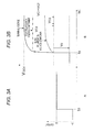
- Fig. 3B shows a voltage relaxation process when current is stopped in the secondary cell 2.
- this voltage relaxation process corresponds to a case where constant current discharge is performed with a current I [A] in the initial stage, and the current is stopped at time to.
- the terminal voltage V C1 + V C2 of the secondary cell 2 converges to the open-circuit voltage value V OCV through the polarization voltage relaxation process from time to when the discharge is stopped.
- the polarization voltage relaxation process can be divided into a component V C1 having a relatively high response speed (hereinafter referred to as the fast polarization voltage component) and a component V C2 having a relatively low response speed (hereinafter referred to as the slow polarization voltage component), as shown in Fig. 3B .
- the slow polarization voltage component depends on the current, the temperature, and the state of charge (SOC) of the secondary cell, and causes the open-circuit voltage value to greatly vary with temperatures and loads.
- SOC state of charge
- the present disclosure is focused on the slow polarization voltage component, and is to sufficiently reduce the estimate error of the open-circuit voltage value even in an environment where the temperature and the load vary greatly.
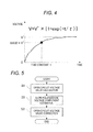
- Fig. 4 shows the relationship between the polarization voltage relaxation process and the time constant in the secondary cell 2.
- the polarization voltage relaxation process can be expressed as an exponential function of a natural number (e).
- the time constant ⁇ becomes smaller as current becomes larger and cell temperature becomes higher. Therefore, the time constant ⁇ is smaller when current is flowing than when current is not flowing.
- the fast polarization voltage component V C1 shown in Figs. 3A and 3B is a component having a relatively small time constant ⁇
- the slow polarization voltage component V C2 is a component having a relatively large time constant ⁇ .
- a slow polarization voltage component has a large time constant and does not respond promptly to changes in the voltage of the secondary cell 2. Therefore, it is considered that a slow polarization voltage component causes an error in estimation of an open-circuit voltage value.
- the time constant of the fast polarization voltage component V C1 is R 1 C 1
- the time constant of the slow polarization voltage component V C2 is R 2 C 2 .
- the secondary cell 2 is not limited to any particular form.
- the secondary cell 2 may be a lithium-ion secondary cell having lithium iron phosphate (LiFePO 4 ) as the cathode material.
- This type of cell is known as a high-security cell.
- a change in the open-circuit voltage value with respect to a state of charge has small characteristics, and therefore, an increase in accuracy of open-circuit voltage value estimation is of significance.
- the present disclosure does not exclude applications to secondary cells other than lithium-ion secondary cells, such as nickel-metal hydride cells.
- the open-circuit voltage estimation device 300 includes an open-circuit voltage calculator 310, a polarization voltage estimator 320, and an open-circuit voltage corrector 330.
- the open-circuit voltage calculator 310 is designed to calculate the open-circuit voltage value of the secondary cell 2.
- the open-circuit voltage calculator 310 is also designed to output the calculated open-circuit voltage value to the open-circuit voltage corrector 330.
- the method used by the open-circuit voltage calculator 310 to calculate an open-circuit voltage value is not particularly limited.
- the open-circuit voltage calculator 310 may be designed to calculate an open-circuit voltage value based on input data that is the results of measurement of the terminal voltage, the current, and the temperature of the secondary cell 2.
- the terminal voltage of the secondary cell 2 may be measured with a voltmeter connected to the secondary cell 2.
- the current in the secondary cell 2 may be measured with an ammeter connected to the secondary cell 2.
- the temperature of the secondary cell 2 may be measured with a thermometer connected to the secondary cell 2.
- the open-circuit voltage calculator 310 may receive an input of the calculated state of charge of the secondary cell 2, and use the input state of charge in calculating an open-circuit voltage value.
- the state of charge is preferably the latest value.
- the open-circuit voltage calculator 310 is not limited to any particular form.
- the open-circuit voltage calculator 310 may be formed with an electronic device or the like.
- the electronic device may include an arithmetic processing unit such as a CPU (Central Processing Unit) or an MPU (Micro-Processing Unit), and storage units such as a RAM (Random Access Memory) and a ROM (Read Only Memory).
- the ROM may store the program and data for realizing the functions of the open-circuit voltage calculator 310.
- the arithmetic processing unit may execute the program stored in the ROM to realize the functions of the open-circuit voltage calculator 310.
- the RAM may be used as the work area of the arithmetic processing unit or the like.
- the open-circuit voltage calculator 310 may include a DSP (Digital Signal Processor).
- the polarization voltage estimator 320 is designed to estimate the component having the largest time constant ⁇ among the polarization voltage components of the secondary cell 2. That is, the polarization voltage estimator 320 is designed to estimate the largest value of the slow polarization voltage component. The polarization voltage estimator 320 is also designed to output the estimated slow polarization voltage component to the open-circuit voltage corrector 330.
- the slow polarization voltage component can also be obtained by dividing the voltage relaxation process at a time of a current stop as shown in Figs. 3A and 3B into a fast polarization voltage component and a slow polarization voltage component by fitting or the like.
- the slow polarization voltage component is not limited to one polarization voltage component. Where there are three or more polarization voltage components, for example, the polarization voltage component having the largest time constant may be regarded as the slow polarization voltage component, or the polarization voltage components having the two or more largest ones of time constants may be regarded as the slow polarization voltage components.
- the slow polarization voltage component may also be the polarization voltage component having a larger time constant than the time length of the input data to be used in one open-circuit voltage value calculation.
- the time length of the input data may be the product of an input period or a sampling period of the input data and the number of pieces or the number of samples in the input data.
- the polarization voltage estimator 320 is not limited to any particular form.
- the polarization voltage estimator 320 may be formed with an electronic device or the like.
- the electronic device may include an arithmetic processing unit such as a CPU or an MPU, and storage units such as a RAM and a ROM.
- the ROM may store the program and data for realizing the functions of the polarization voltage estimator 320.
- the arithmetic processing unit may execute the program stored in the ROM to realize the functions of the polarization voltage estimator 320.
- the RAM may be used as the work area of the arithmetic processing unit or the like.
- the polarization voltage estimator 320 may share part of the hardware with the open-circuit voltage calculator 310, or may be a structure that is completely independent of the open-circuit voltage calculator 310.
- the open-circuit voltage corrector 330 is designed to correct the open-circuit voltage value calculated by the open-circuit voltage calculator 310 with the largest value of the slow polarization voltage component estimated by the polarization voltage estimator 320 (hereinafter referred to simply as the slow polarization voltage component).
- the open-circuit voltage corrector 330 may add the slow polarization voltage component estimated by the polarization voltage estimator 320 to the open-circuit voltage value calculated by the open-circuit voltage calculator 310. In a case where the amount of charge is larger than the amount of discharge in the secondary cell 2, or in the case of overcharge, open-circuit voltage corrector 330 may subtract the slow polarization voltage component estimated by the polarization voltage estimator 320 from the open-circuit voltage value calculated by the open-circuit voltage calculator 310.
- the open-circuit voltage values in such cases can be represented by the following expressions (1).
- V OCV V ⁇ OCV - ⁇ ⁇ V diff - L , I ⁇ 0 overcharge
- V OCV V ⁇ OCV + ⁇ ⁇ V diff - L , I ⁇ 0 overdischarge
- V OCV represents the open-circuit voltage value after correction.
- V' OCV represents the open-circuit voltage value prior to correction.
- ⁇ V diff-L represents the slow polarization voltage component.
- I represents current.
- the open-circuit voltage corrector 330 is not limited to any particular form.
- the open-circuit voltage corrector 330 may be formed with an electronic device or the like.
- the electronic device may include an arithmetic processing unit such as a CPU or an MPU, and storage units such as a RAM and a ROM.
- the ROM may store the program and data for realizing the functions of the open-circuit voltage corrector 330.
- the arithmetic processing unit may execute the program stored in the ROM to realize the functions of the open-circuit voltage corrector 330.
- the RAM may be used as the work area of the arithmetic processing unit or the like.
- the open-circuit voltage corrector 330 may share part of the hardware with the open-circuit voltage calculator 310 and the polarization voltage estimator 320, or may be a completely independent structure.
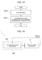
- Fig. 5 is a flowchart showing an example operation of the power storage apparatus 1 of this embodiment.
- the example operation shown in Fig. 5 includes an embodiment of an open-circuit voltage estimation method according to the present disclosure.
- an open-circuit voltage estimation method according to the present disclosure may be embodied with a structure other than the power storage apparatus 1.
- step 1 (S1) in Fig. 5 the open-circuit voltage calculator 310 calculates an open-circuit voltage value.
- the polarization voltage estimator 320 estimates a slow polarization voltage component. Step 2 (S2) may be carried out before step 1 (S1), or may be carried out at the same time as step 1 (S1).
- step 3 the open-circuit voltage corrector 330 corrects the open-circuit voltage value calculated in step 1 (S1) with the slow polarization voltage component estimated in step 2 (S2).
- the open-circuit voltage calculated in step 1 (S1) is assumed to be lower than the true value of the open-circuit voltage value represented by the correct open-circuit voltage value curve shown in Fig. 6A due to overdischarge.
- Fig. 6A shows a charge-discharge curve indicating overdischarge.
- the open-circuit voltage value is upwardly revised with the slow polarization voltage component estimated in step 2 (S2) to a value that is the same or close to the true value of the open-circuit voltage value, as shown in Fig. 6B .
- an open-circuit voltage value can be estimated with high precision even in an environment where temperature and load vary greatly, with the slow polarization voltage component being taken into account. Also, in the power storage apparatus 1 of this embodiment, an open-circuit voltage value can be estimated with high precision in an actually used state or at a time of charge/discharge. High-precision estimation of an open-circuit voltage value leads to high-precision sensing of a state of charge, and accordingly, high reliability of the sensed state of charge of the secondary cell 2 can be secured.
- Fig. 7 is a diagram schematically showing an example structure of a power storage apparatus 1 according to a first modification of this embodiment.
- the power storage apparatus 1 of this modification differs from the power storage apparatus 1 of Fig. 1 in calculating a state of charge.
- the power storage apparatus 1 of this modification includes a state-of-charge calculator 4 connected to an open-circuit voltage estimation device 300.
- the state-of-charge calculator 4 is in a stage after the open-circuit voltage estimation device 300.
- the state-of-charge calculator 4 is designed to receive the data of an open-circuit voltage value estimated by the open-circuit voltage estimation device 300 or an open-circuit voltage value corrected by the open-circuit voltage corrector 330.
- the state-of-charge calculator 4 is designed to calculate the state of charge of the secondary cell 2 based on the open-circuit voltage value that has been input.
- the method of calculating a state of charge is not limited to any particular method.
- the state-of-charge calculator 4 may uniquely calculate a state of charge based on data that shows the correspondence relationship between the open-circuit voltage value and the state of charge as shown in Fig. 8 .
- the data showing the correspondence relationship as in Fig. 8 may be pointwise data shown in a table, for example.
- the state-of-charge calculator 4 is not limited to any particular form.
- the state-of-charge calculator 4 may be formed with an electronic device or the like.
- the electronic device may include an arithmetic processing unit such as a CPU or an MPU, and storage units such as a RAM and a ROM.
- the ROM may store the program and data for realizing the functions of the state-of-charge calculator 4.
- the arithmetic processing unit may execute the program stored in the ROM to realize the functions of the state-of-charge calculator 4.
- the RAM may be used as the work area of the arithmetic processing unit or the like.
- the state-of-charge calculator 4 may share part of the hardware with the open-circuit voltage estimation device 300, or may be a structure that is completely independent of the open-circuit voltage estimation device 300.
- Fig. 9 is a flowchart showing an example operation of the power storage apparatus 1 of this modification.
- the example operation shown in Fig. 9 includes an embodiment of an open-circuit voltage estimation method according to the present disclosure.
- step 4 (S4) is carried out after step 3 (S3) shown in Fig. 5 .
- the state-of-charge calculator 4 calculates the state of charge based on the open-circuit voltage value corrected in step 3 (S3).
- Fig. 10 is a diagram schematically showing an example structure of a power storage apparatus 1 of this embodiment.
- the power storage apparatus 1 of this embodiment differs from the power storage apparatus 1 of Fig. 1 in the structure of the polarization voltage estimator 320. This aspect will be described below in detail.
- the polarization voltage estimator 320 of this embodiment includes an average calculator 321 and a polarization voltage calculator 322.
- the average calculator 321 is designed to receive, from the side of the secondary cell 2, an input of at least one measured value of the current and the temperature of the secondary cell 2.
- the average calculator 321 is designed to calculate the average value(s) of the current and/or the temperature of the secondary cell 2 based on the input measured value(s).
- the average calculator 321 is also designed to output the calculated average value(s) to the polarization voltage calculator 322.
- the average value(s) is (are) not limited to any particular form(s).
- the average value(s) may be the arithmetic average value(s) or the like of a predetermined number of inputs or a predetermined number of samples of measured values of the current and/or the temperature, but is (are) not limited to that (them).
- the polarization voltage calculator 322 is designed to calculate a slow polarization voltage component based on the average value(s) input from the average calculator 321.
- the method of calculating a slow polarization voltage component based on the average value(s) is not limited to any particular method.
- the polarization voltage calculator 322 may calculate the slow polarization voltage component by putting the average value(s) into an already acquired correspondence relationship between the slow polarization voltage component and the current and/or the temperature of the secondary cell 2.
- the correspondence relationship may also involve the state of charge.
- Fig. 11 is a flowchart showing an example operation of the power storage apparatus 1 of this embodiment.
- the example operation shown in Fig. 11 includes an embodiment of an open-circuit voltage estimation method according to the present disclosure.
- step 21 (S21) the average calculator 321 acquires the current and/or the temperature of the secondary cell 2.
- step 22 (S22) the average calculator 321 calculates the average value(s) of the current and/or the temperature of the secondary cell 2 acquired in step 21 (S21).
- step 23 (S23) the polarization voltage calculator 322 calculates the slow polarization voltage component based on the average value(s) calculated in step 22 (S22).
- the same effects as those of the power storage apparatus 1 of Fig. 1 can be achieved, and the calculation of the slow polarization voltage component that depends on the current and the temperature of the secondary cell 2 can be simplified by using the average value(s).
- a power storage apparatus 1 of this modification differs from the power storage apparatus 1 of Fig. 10 in the structure of the polarization voltage calculator 322.
- the polarization voltage calculator 322 of this modification is designed to calculate the slow polarization voltage component based on a table that is acquired beforehand and shows the correspondence relationship between average values and the slow polarization voltage component as shown in Fig. 12 , for example.
- the table may be stored in the storage area of the polarization voltage calculator 322, but is not limited to this arrangement.
- Fig. 13 is a flowchart showing an example operation of the power storage apparatus 1 of this modification.
- the example operation shown in Fig. 13 includes an embodiment of an open-circuit voltage estimation method according to the present disclosure.
- step 231 the polarization voltage calculator 322 refers to the table.
- step 232 the polarization voltage calculator 322 unambiguously identifies the slow polarization voltage component corresponding to the average value(s) calculated in step 22 (S22) of Fig. 11 from the table, and sets the identified slow polarization voltage component as the calculation result.
- the same effects as those of the power storage apparatus 1 of Fig. 10 can be achieved, and the slow polarization voltage component can be readily and quickly calculated with a small operational load and low power consumption.
- a power storage apparatus 1 of this modification differs from the power storage apparatus 1 described with reference to Fig. 12 in the structure of the polarization voltage estimator 320.
- the data of the last or the latest state of charge calculated by the state-of-charge calculator 4 is input to or fed back to the polarization voltage calculator 322.
- the polarization voltage calculator 322 is designed to calculate a slow polarization voltage component by referring to the correspondence relationship in the table in accordance with the state of charge acquired from the state-of-charge calculator 4 or the correspondence relationship between the slow polarization voltage component and the current and/or the temperature of the secondary cell 2.
- the table shows the correspondence relationship between the slow polarization voltage component and the current and/or the temperature of the secondary cell 2 in relation to the state of charge.
- the table is not limited to any particular form. For example, a different table may be prepared and stored for each state of charge, as shown in Fig. 15 .
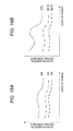
- the slow polarization voltage component characteristically depends on the current and the state of charge.
- the slow polarization voltage component also characteristically depends on the cell temperature and the state of charge. If the table shown in Fig. 15 is created based on the characteristics shown in Figs. 16A and 16B , the dependence of the slow polarization voltage component on the current, the temperature, and the state of charge can be appropriately reflected by the table. In this manner, the accuracy of slow polarization voltage component estimation can be readily increased.
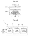
- Fig. 17 is a flowchart showing an example operation of the power storage apparatus 1 of this modification.
- the example operation shown in Fig. 17 includes an embodiment of an open-circuit voltage estimation method according to the present disclosure.
- step 2311 the polarization voltage calculator 322 acquires the state of charge from the state-of-charge calculator 4.
- step 2312 the polarization voltage calculator 322 refers to the table showing the correspondence relationship corresponding to the state of charge acquired in step 2311 (S2311).
- a power storage apparatus 1 of this modification differs from the power storage apparatus 1 of Fig. 10 in the structure of the polarization voltage estimator 320.
- the polarization voltage estimator 320 of this modification includes a divisor calculator 323.
- the divisor calculator 323 is designed to calculate the divisor to be used by the average calculator 321 to calculate the average value(s).
- the divisor calculator 323 may calculate the divisor by using the table shown in Fig. 19B , for example.
- the table in Fig. 19B shows the correspondence relationship among the temperature and the current of the secondary cell 2 and the timing information [sec] pertaining to the divisor.
- the table in Fig. 19B is the table corresponding to a state of charge of 60%, but the divisor calculator 323 may be designed to refer to a different table for each state of charge.
- Fig. 19A is a table in which the temperature and the current of the secondary cell 2 are allocated in the same pattern as in Fig. 19B , and the table shows the relationship among the temperature, the current, and the slow polarization voltage component.
- the timing information pertaining to the divisor in Fig. 19B may correspond to the time constant of the slow polarization voltage component associated with the same temperature and the same current in Fig. 19A .
- this time constant may be the time constant of the current-flowing slow polarization voltage component determined by fitting or the like from the voltage trajectory at a time of switching from constant current charge to constant current discharge.
- the divisor calculator 323 may be designed to calculate the divisor to be used in calculating the next average value(s) by referring to the table shown in Fig. 19B .
- the divisor calculator 323 acquires 60 seconds as the timing information pertaining to the divisor.
- the divisor calculator 323 may divide the acquired timing information (60 seconds) by a predetermined operation period (one second, for example), to determine the divisor (60, for example) to be used in calculating the next average values of the temperature and the current. Since a temperature change is slower than a current change, the table shown in Fig. 19B does not exclude applications to divisor calculations based on one measured value of temperature, instead of an average value. That is, cases where one measured value of temperature is used in calculating a slow polarization voltage component are also within the scope of the present disclosure.
- I avg represents the average value of current at time t.
- I t-1 is the previous value of current.
- N represents the divisor.
- T avg represents the average value of temperature at time t.
- T t-1 is the previous temperature.
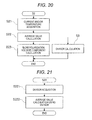
- Fig. 20 is a first flowchart showing an example operation of the power storage apparatus 1 of this modification.
- the example operation shown in Fig. 20 includes an embodiment of an open-circuit voltage estimation method according to the present disclosure.
- step 5 (S5) is carried out after step 22 (S22) shown in Fig. 11 .
- step 5 (S5) the divisor calculator 323 calculates the divisor to be used in calculating the next average value(s) based on the average value(s) calculated in step 22 (S22).
- step 221 (S221) the average calculator 321 acquires a divisor from the divisor calculator 323.
- step 222 (S222) the average calculator 321 calculates the average value(s) of the current and/or the temperature of the secondary cell 2 by using the divisor acquired in step 221 (S221).
- step 51 (S51) a series of procedures of steps 51 (S51) and 52 (S52) of Fig. 22 are further carried out as a specific example of step 5 (S5) of Fig. 20 .
- the divisor calculator 323 refers to the table corresponding to the present state of charge, and determines the timing information pertaining to the divisor corresponding to the current and the cell temperature at present.
- step 52 (S52) the divisor calculator 323 calculates the divisor by dividing the timing information determined in step 51 (S51) by a predetermined operation period.
- the same effects as those of the power storage apparatus 1 of Fig. 14 can be achieved, and average values that flexibly reflect time-dependent changes in current and cell temperature can be dynamically calculated.
- a power storage apparatus 1 of this modification differs from the power storage apparatus 1 described with reference to Fig. 12 in the structure of the polarization voltage estimator 320.
- the power storage apparatus 1 of this modification is designed to estimate slow polarization voltage components having different time constants from one another, with the secondary cell 2 being regarded as an equivalent circuit including three or more RC parallel circuits.
- a table that shows the correspondence relationship among the cell temperature, the current, and the slow polarization voltage components as shown in Fig. 24 may be used.
- the calculation of each slow polarization voltage component with reference to a table and the correction of an open-circuit voltage value with each calculated slow polarization voltage component are the same as those described above with reference to Fig. 13 and others.
- a power storage apparatus 1 of this embodiment differs from the power storage apparatus 1 of Fig. 18 in the structure of the polarization voltage calculator 322.
- the polarization voltage calculator 322 is designed to calculate a slow polarization voltage component by interpolating a value in a table when the table does not include the value corresponding to an average value calculated by an average calculator 321.
- the table shown in Fig. 19A may be used, for example.
- the type of interpolation is not particularly limited.
- the polarization voltage calculator 322 may be designed to perform linear interpolation, spline interpolation, or the like.
- the polarization voltage calculator 322 may also be designed to perform linear interpolation by using the value closest to an average value in the table.
- the example operation described below includes an embodiment of an open-circuit voltage estimation method according to the present disclosure.
- the polarization voltage calculator 322 may perform linear interpolation according to the following equation (3).
- V V H - V L I H - I L ⁇ I avg + I H ⁇ V L - I L ⁇ V H I H - I L
- V represents the slow polarization voltage component calculated through the linear interpolation.
- I avg represents the average current value calculated by the average calculator 321.
- I H represents the current value that exists in the table and is the value closest to I avg on the high-current side.
- I L represents the current value that exists in the table and is the value closest to I avg on the low-current side.
- V H represents the slow polarization voltage component that exists in the table and is the value corresponding to I H .
- V L represents the slow polarization voltage component that exists in the table and is the value corresponding to I L .
- V in the equation (3) satisfies the relationship represented by the linear function shown in Fig. 25 , with I being the variable. In the linear function in Fig.
- (V H - V L ) / (I H - I L ) represents the slope
- (I H V L -I L V H ) / (I H - I L ) represents the intercept on the slow polarization voltage component side.
- the polarization voltage calculator 322 When sensing that the temperature corresponds to a value in the table but the current does not correspond to any value in the table, the polarization voltage calculator 322 extracts the two points I L and I H closest to I avg from the table, and also extracts the slow polarization voltage components V L and V H corresponding to the two points I L and I H from the table. The polarization voltage calculator 322 may then plug the extracted values I L , I H , V L , and V H , and the value I avg acquired from the average calculator 321 into the equation (3), to calculate the slow polarization voltage component.
- the average temperature value calculated by the average calculator 321 is 20°C, and there exists the corresponding temperature value (20°C) in the table, for example.
- the average current value I avg calculated by the average calculator 321 is 3 A, and the table does not include the corresponding current value (3 A), for example.
- 2 A is extracted as I L
- 4 A is extracted as I H from the fields corresponding to 20°C.
- 10 mV is extracted as V L
- 20 mV is extracted as V H from the fields corresponding to 20°C.
- 15 mV is obtained as the slow polarization voltage component.
- the polarization voltage calculator 322 may perform linear interpolation according to the following equation (4).
- V V H - V L T H - T L ⁇ T avg + T H ⁇ V L - T L ⁇ V H T H - T L
- V represents the slow polarization voltage component calculated through the linear interpolation.
- T avg represents the average temperature value calculated by the average calculator 321.
- T H represents the temperature value that exists in the table and is the value closest to T avg on the high-temperature side.
- T L represents the temperature value that exists in the table and is the value closest to T avg on the low-temperature side.
- V H represents the slow polarization voltage component that exists in the table and is the value corresponding to T H .
- V L represents the slow polarization voltage component that exists in the table and is the value corresponding to T L .
- V in the equation (4) satisfies the relationship represented by the linear function shown in Fig. 26 , with T being the variable. In the linear function in Fig.
- (V H - V L ) / (T H - T L ) represents the slope
- (T H V L - T L V H ) / (T H - T L ) represents the intercept on the slow polarization voltage component side.
- the calculation of the slow polarization voltage component according to the equation (4) is the same as that in the case where the equation (3) is used, and therefore, explanation thereof will not be made herein.
- the polarization voltage calculator 322 may perform linear interpolation involving the following steps, for example.
- the average temperature value calculated by the average calculator 321 is 24°C, and the table does not include the corresponding temperature value, for example.
- the average current value I avg calculated by the average calculator 321 is 3 A, and the table does not include the corresponding current value, for example.
- the slow polarization voltage component corresponding to the temperature of 24°C and the current of 3 A is determined to be 13.2 mV.
- the same effects as those of the power storage apparatus 1 of Fig. 18 can be achieved, and the slow polarization voltage component can be appropriately calculated even when the resolution of the table is low.
- a power storage apparatus 1 of this embodiment differs from the power storage apparatus 1 of the third embodiment in the structure of the open-circuit voltage calculator 310.
- the open-circuit voltage calculator 310 of this embodiment includes a digital filter 311.
- the digital filter 311 is designed to update the parameters R 1 , R 2 , C 1 , C 2 , and the like of the equivalent circuit shown in Fig. 2 based on measured values of the voltage and the current of the secondary cell 2.
- the open-circuit voltage calculator 310 is designed to dynamically calculate an open-circuit voltage value by using the parameters updated by the digital filter 311.
- the digital filter 311 is not limited to any particular form.
- the digital filter 311 may be an adaptive filter or the like, or may be a Kalman filter or the like.
- Fig. 28 is a flowchart showing an example operation of the power storage apparatus 1 of this embodiment.
- the example operation shown in Fig. 28 includes an embodiment of an open-circuit voltage estimation method according to the present disclosure.
- step 11 the digital filter 311 updates the parameters of the equivalent circuit.
- step 12 the open-circuit voltage calculator 310 calculates an open-circuit voltage value from the parameters updated in step 11 (S11) and the input values of voltage, current, and temperature.
- a power storage apparatus 1 of this modification differs from the power storage apparatus 1 of Fig. 27 in that the digital filter 311 is an adaptive filter.
- the impedance between the terminals of the secondary cell 2 is expressed by the following equation (5).
- R 0 + 1 1 R 1 + j ⁇ ⁇ ⁇ C 1 + 1 1 R 2 + j ⁇ ⁇ ⁇ C 2 R 0 + R 1 1 + + j ⁇ ⁇ ⁇ R 1 ⁇ C 1 + R 2 1 + j ⁇ ⁇ ⁇ R 2 ⁇ C 2
- V s R 0 + R 1 1 + R 1 ⁇ C 1 ⁇ s + R 2 1 + R 2 ⁇ C 2 ⁇ s ⁇ I s + V ocv s
- a 1 , a 2 , b 0 , b 1 , and b 2 are variables represented by R 0 , R 1 , R 2 , C 1 , and C 2 in the equivalent circuit, and an operation period Ts.
- V k - a 1 ⁇ V ⁇ k - 1 - a 2 ⁇ V ⁇ k - 2 + b 0 ⁇ I k + b 1 ⁇ I ⁇ k - 1 + b 2 ⁇ I ⁇ k - 2 + 1 + a 1 + a 2 ⁇ V OCV k V OCV k ⁇ V OCV ⁇ k - 1 ⁇ V OCV ⁇ k - 2
- V ⁇ k - 1 - a 1 ⁇ V ⁇ k - 2 - a 2 ⁇ V ⁇ k - 3 + b 0 ⁇ I ⁇ k - 1 + b 1 ⁇ I ⁇ k - 2 + b 2 ⁇ I ⁇ k - 3 + 1 + a 1 + a 2 ⁇ V OCV ⁇ k - 1
- a voltage change ⁇ V(k) is expressed by the following equations (11).
- ⁇ represents a data matrix.
- ⁇ represents the coefficient matrix of an equivalent circuit model.
- the superscript "t” represents matrix transposition.
- P represents a covariance matrix.
- ⁇ represents an identification error.
- ⁇ represents a positive number that is called a forgetting factor and is equal to or smaller than 1.
- the superscript " ⁇ " represents an estimated value.
- V OCV (k) an open-circuit voltage value V OCV (k) is calculated according to the following equation (14).
- V ocv k 1 1 + a 1 + a 2 V k + a 1 ⁇ V ⁇ k - 1 + a 2 ⁇ V ⁇ k - 2 - b 0 ⁇ I k - b 1 ⁇ I ⁇ k - 1 - b 2 ⁇ I ⁇ k - 2
- an open-circuit voltage value is calculated by using an adaptive filter. Accordingly, an open-circuit voltage with a certain degree of precision can be obtained as the open-circuit voltage value yet to be subjected to the correction by the open-circuit voltage corrector 330, regardless of non-linear changes in polarization voltage.
- the time length of the input data to be used in one calculation by an adaptive filter (three seconds when the sampling period is one second and the number of input samples is three, for example) is smaller than the time constant of the slow polarization voltage component (60 seconds, for example).
- a power storage apparatus 1 of this embodiment differs from the power storage apparatus 1 of any of the first through fourth embodiments in the structure of the open-circuit voltage estimation device 300.
- the open-circuit voltage estimation device 300 of this embodiment is designed to estimate an open-circuit voltage based on terminal voltage information, current information, cell temperature information about the secondary cell 2 acquired through communication.
- Fig. 29 shows a more specific example structure.
- the power storage apparatus 1 includes a first communication device 5.
- the open-circuit voltage estimation device 300 receives terminal voltage information, current information, and cell temperature information about the secondary cell 2 through communication via the first communication device 5. Based on the received information, the open-circuit voltage estimation device 300 calculates an open-circuit voltage value with the open-circuit voltage calculator 310, estimates a slow polarization voltage component with the polarization voltage estimator 320, and corrects the open-circuit voltage value with the open-circuit voltage corrector 330.
- the open-circuit voltage estimation device 300 may be located in a position that is isolated from the secondary cell 2.
- the open-circuit voltage estimation device 300 may be connected to and communicate with a structure on the side of the secondary cell 2 via a network.
- the network may be an external network or the like.
- the external network may be the Internet or the like.
- the open-circuit voltage estimation device 300 may be a server or the like on the Internet.
- the method to be used by the open-circuit voltage estimation device 300 to receive information about the secondary cell 2 is not particularly limited, and reception of information about the secondary cell 2 by the open-circuit voltage estimation device 300 through any route is included in the scope of the present disclosure.
- the communication method to be used by the first communication device 5 is not limited to any particular method, either.
- the first communication device 5 may be included in the open-circuit voltage estimation device 300.
- Fig. 30 is a flowchart showing an example operation of the power storage apparatus 1 of this embodiment.
- the example operation shown in Fig. 30 includes an embodiment of an open-circuit voltage estimation method according to the present disclosure.
- step 6 (S6) is carried out before step 1 (S1) of Fig. 5 .
- the open-circuit voltage estimation device 300 receives terminal voltage information, current information, and cell temperature information about the secondary cell 2 through communication.
- the trigger for the reception is not particularly limited.
- the side of the open-circuit voltage estimation device 300 may request the information about the secondary cell 2 from the side of the secondary cell 2, and the side of the secondary cell 2 may respond to the request.
- the information about the secondary cell 2 may be constantly or regularly transmitted from the side of the secondary cell 2 to the side of the open-circuit voltage estimation device 300.
- the same effects as those of the first through fourth embodiments can be achieved, and the single open-circuit voltage estimation device 300 can estimate open-circuit voltage values of secondary cells 2 placed at various locations.
- a power storage apparatus 1 of this modification differs from the power storage apparatus 1 of Fig. 29 in the structure on the side of the secondary cell 2. Specifically, as shown in Fig. 31 , the power storage apparatus 1 of this modification further includes a voltmeter 6, an ammeter 7, and a thermometer 8 that are connected to the secondary cell 2, and a second communication device 9 connected to the respective measuring instruments 6, 7, and 8.
- the voltmeter 6 is designed to measure the terminal voltage of the secondary cell 2 and output the measurement result to the second communication device 9.
- the ammeter 7 is designed to measure the charging/discharging current of the secondary cell 2 and output the measurement result to the second communication device 9.
- the thermometer 8 is designed to measure the temperature of the secondary cell 2 and output the measurement result to the second communication device 9.
- the second communication device 9 is designed to transmit the measurement information from the measuring instruments 6 through 8 to the open-circuit voltage estimation device 300.
- the measuring instruments 6 through 8 and the second communication device 9 are not limited to any particular forms.
- Fig. 32 is a flowchart showing an example operation of the power storage apparatus 1 of this embodiment.
- the example operation shown in Fig. 32 includes an embodiment of an open-circuit voltage estimation method according to the present disclosure.
- step 7 the voltmeter 6 measures the terminal voltage of the secondary cell 2 and outputs the measurement result to the second communication device 9.
- step 8 (S8) the ammeter 7 measures the current in the secondary cell 2 and outputs the measurement result to the second communication device 9.
- step 9 (S9) the thermometer 8 measures the temperature of the secondary cell 2 and outputs the measurement result to the second communication device 9.
- Steps 7 (S7) through 9 (S9) may be carried out in any order, or may be simultaneously carried out.
- step 10 (S10) the second communication device 9 transmits the measurement results received from the measuring instruments 6 through 8 to the side of the open-circuit voltage estimation device 300.
- the power storage apparatus 1 is not limited to any particular use, and may be suitably used for various loads in public, industrial, or household electricity storage systems, emergency power sources, or vehicles such as hybrid cars and electric vehicles.
- emergency power sources or vehicles such as hybrid cars and electric vehicles.
- the present disclosure is applied to an emergency power source, it is possible to prevent an unexpected blackout due to inconsistency between an actual state of charge and a displayed state of charge in spite of an indication of a sufficient amount of remaining power on the display, for example.
- the present disclosure is applied to a vehicle, the vehicle can be prevented from unexpectedly stopping and failing to reach a destination in spite of an indication of a sufficient amount of remaining power on the display.
- the power source that supplies energy to the secondary cell(s) 2 is not limited to any particular form, and may be any of the power sources for solar cells, wind power generators, power plants, and secondary cells having surplus power.
- the present disclosure may also be embodied in the structures described below.
Landscapes
- Physics & Mathematics (AREA)
- General Physics & Mathematics (AREA)
- Secondary Cells (AREA)
- Tests Of Electric Status Of Batteries (AREA)
Abstract
Description
- This application claims the benefit of Japanese Priority Patent Application
JP 2013-216454 filed on October 17, 2013 - The present disclosure relates to an open-circuit voltage estimation device, a power storage apparatus, and an open-circuit voltage estimation method. More particularly, the present disclosure relates to an open-circuit voltage estimation device that estimates an open-circuit voltage value, a power storage apparatus, and an open-circuit voltage estimation method.
- There have been techniques for estimating an open-circuit voltage (OCV) value of a secondary cell. For example,
JP 2004-14231 A -
JP 2004-14231 A - It is preferable to estimate an open-circuit voltage value with high precision.
- The present disclosure provides an open-circuit voltage estimation device that estimates an open-circuit voltage value with high precision, a power storage apparatus, and an open-circuit voltage estimation method.
- An open-circuit voltage estimation device according to the present disclosure includes: an open-circuit voltage calculator that calculates an open-circuit voltage value of a secondary cell; a polarization voltage estimator that estimates a component having a relatively large time constant among polarization voltage components of the secondary cell; and an open-circuit voltage corrector that corrects the open-circuit voltage value calculated by the open-circuit voltage calculator with the component having the relatively large time constant estimated by the polarization voltage estimator.
- The polarization voltage estimator may include: an average calculator that calculates an average value of at least one of current and cell temperature of the secondary cell; and a polarization voltage calculator that calculates the component having the relatively large time constant based on the average value calculated by the average calculator.
- In this case, the polarization voltage calculator may calculate the component having the relatively large time constant based on a table that is acquired beforehand and shows the correspondence relationship between the average value and the component having the relatively large time constant.
- In this case, the table may show the correspondence relationship in accordance with the state of charge of the secondary cell, and the polarization voltage calculator may calculate the component having the relatively large time constant by referring to the correspondence relationship corresponding to the acquired state of charge. The polarization voltage estimator may include a divisor calculator that calculates the divisor to be used by the average calculator in calculating the average value. The polarization voltage calculator may calculate the component having the relatively large time constant by interpolating a value in the table.
- The open-circuit voltage estimation device may further include a state-of-charge calculator that calculates the state of charge of the secondary cell based on the open-circuit voltage value corrected by the open-circuit voltage corrector, the state-of-charge calculator being connected to the open-circuit voltage estimation device. The open-circuit voltage calculator may include a digital filter.
- In the open-circuit voltage estimation device, the open-circuit voltage value corrected with the component having the relatively large time constant may be estimated based on terminal voltage information, current information, and cell temperature information about the secondary cell, the terminal voltage information, the current information, and the cell temperature information being acquired through communication.
- A power storage apparatus according to the present disclosure includes a secondary cell, and an open-circuit voltage estimation device, wherein the open-circuit voltage estimation device includes: an open-circuit voltage calculator that calculates an open-circuit voltage value of a secondary cell; a polarization voltage estimator that estimates a component having a relatively large time constant among the polarization voltage components of the secondary cell; and an open-circuit voltage corrector that corrects the open-circuit voltage value calculated by the open-circuit voltage calculator with the component having the relatively large time constant estimated by the polarization voltage estimator. An open-circuit voltage estimation method according to the present disclosure includes correcting a calculated open-circuit voltage value of a secondary cell with an estimated component having a relatively large time constant among the polarization voltage components of the secondary cell.
- According to the present disclosure, an open-circuit voltage value can be estimated with high precision.
-
- [
Fig. 1 ]
Fig. 1 is a diagram schematically showing an example structure of a power storage apparatus according to a first embodiment of the present disclosure; - [
Fig. 2 ]
Fig. 2 is an equivalent circuit diagram of a secondary cell for explaining the example structure of the power storage apparatus according to the first embodiment of the present disclosure; - [
Fig. 3 ]
Figs. 3A and 3B are timing charts illustrating the characteristics of a secondary cell for explaining the example structure of the power storage apparatus according to the first embodiment of the present disclosure:Fig. 3A is a timing chart showing current; andFig. 3B is a timing chart showing a voltage relaxation process when the current flow is stopped; - [
Fig. 4 ]
Fig. 4 is a timing chart for explaining the example structure of the power storage apparatus according to the first embodiment of the present disclosure, showing the relationship between a polarization voltage relaxation process in a secondary cell and time constant; - [
Fig. 5 ]
Fig. 5 is a flowchart showing an example operation of the power storage apparatus according to the first embodiment of the present disclosure; - [
Fig. 6 ]
Figs. 6A and 6B are timing charts for explaining the example operation of the power storage apparatus according to the first embodiment of the present disclosure:Fig. 6A is a timing chart showing a case where correction is not performed with a component having a relatively large time constant; andFig. 6B is a timing chart showing a case where correction is performed with a component having a relatively large time constant; - [
Fig. 7 ]
Fig. 7 is a diagram schematically showing an example structure of a power storage apparatus according to a first modification of the first embodiment of the present disclosure; - [
Fig. 8 ]
Fig. 8 is a graph for explaining the example structure of the power storage apparatus according to the first modification of the first embodiment of the present disclosure, showing the correspondence relationship between the state of charge and the open-circuit voltage value; - [
Fig. 9 ]
Fig. 9 is a flowchart showing an example operation of the power storage apparatus according to the first modification of the first embodiment of the present disclosure; - [
Fig. 10 ]
Fig. 10 is a diagram schematically showing an example structure of a power storage apparatus according to a second embodiment of the present disclosure; - [
Fig. 11 ]
Fig. 11 is a flowchart showing an example operation of the power storage apparatus according to the second embodiment of the present disclosure; - [
Fig. 12 ]
Fig. 12 is a schematic diagram for explaining an example structure of a power storage apparatus according to a first modification of the second embodiment of the present disclosure, showing a table that shows the correspondence relationship among cell temperature, current, and a component having a relatively large time constant; - [
Fig. 13 ]
Fig. 13 is a flowchart showing an example operation of the power storage apparatus according to the first modification of the second embodiment of the present disclosure; - [
Fig. 14 ]
Fig. 14 is a diagram schematically showing an example structure of a power storage apparatus according to a second modification of the second embodiment of the present disclosure; - [
Fig. 15 ]
Fig. 15 is a schematic diagram for explaining the example structure of the power storage apparatus according to the second modification of the second embodiment of the present disclosure, showing tables that show the correspondence relationship among cell temperature, current, and a component having a relatively large time constant, and vary with states of charge; - [
Fig. 16 ]
Figs. 16A and 16B are graphs for explaining an example structure of the power storage apparatus according to the second embodiment of the present disclosure:Fig. 16A is a graph showing the correspondence relationship among current, the state of charge, and a component having a relatively large time constant; andFig. 16B is a graph showing the correspondence relationship among cell temperature, the state of charge, and a component having a relatively large time constant; - [
Fig. 17 ]
Fig. 17 is a flowchart showing an example operation of the power storage apparatus according to the second modification of the second embodiment of the present disclosure; - [
Fig. 18 ]
Fig. 18 is a diagram schematically showing an example structure of a power storage apparatus according to a third modification of the second embodiment of the present disclosure; - [
Fig. 19 ]
Figs. 19A and 19B are graphs for explaining the example structure of the power storage apparatus according to the third modification of the second embodiment of the present disclosure:Fig. 19A is a graph showing the correspondence relationship among cell temperature, current, and a component having a relatively large time constant; andFig. 19B is a graph showing the correspondence relationship among cell temperature, current, and timing information for calculating a divisor; - [
Fig. 20 ]
Fig. 20 is a first flowchart showing an example operation of the power storage apparatus according to the third modification of the second embodiment of the present disclosure; - [
Fig. 21 ]
Fig. 21 is a second flowchart showing an example operation of the power storage apparatus according to the third modification of the second embodiment of the present disclosure; - [
Fig. 22 ]
Fig. 22 is a third flowchart showing an example operation of the power storage apparatus according to the third modification of the second embodiment of the present disclosure; - [
Fig. 23 ]
Fig. 23 is an equivalent circuit diagram of a secondary cell for explaining an example structure of a power storage apparatus according to a fourth modification of the second embodiment of the present disclosure; - [
Fig. 24 ]
Fig. 24 is a schematic diagram for explaining the example structure of the power storage apparatus according to the fourth modification of the second embodiment of the present disclosure, showing a table that shows the correspondence relationship among cell temperature, current, and a component having a relatively large time constant; - [
Fig. 25 ]
Fig. 25 is a graph for explaining linear interpolation to be performed when the cell temperature corresponds to a value in the table and the current does not correspond to a value in the table in an example operation of a power storage apparatus according to a third embodiment of the present disclosure; - [
Fig. 26 ]
Fig. 26 is a graph for explaining linear interpolation to be performed when the current corresponds to a value in the table and the cell temperature does not correspond to a value in the table in an example operation of the power storage apparatus according to the third embodiment of the present disclosure; - [
Fig. 27 ]
Fig. 27 is a diagram schematically showing an example structure of a power storage apparatus according to a fourth embodiment of the present disclosure; - [
Fig. 28 ]
Fig. 28 is a flowchart showing an example operation of the power storage apparatus according to the fourth embodiment of the present disclosure; - [
Fig. 29 ]
Fig. 29 is a diagram schematically showing an example structure of a power storage apparatus according to a fifth embodiment of the present disclosure; - [
Fig. 30 ]
Fig. 30 is a flowchart showing an example operation of the power storage apparatus according to the fifth embodiment of the present disclosure; - [
Fig. 31 ]
Fig. 31 is a diagram schematically showing an example structure of a power storage apparatus according to a first modification of the fifth embodiment of the present disclosure; and - [
Fig. 32 ]
Fig. 32 is a flowchart showing an example operation of the power storage apparatus according to the first modification of the fifth embodiment of the present disclosure. - The following is a description of preferred embodiments for carrying out the present disclosure, with reference to the accompanying drawings. The embodiments described below are typical examples of embodiments of the present disclosure, and do not narrow the interpretation of the scope of the present disclosure. In the respective embodiments, corresponding components are denoted by same reference numerals, and explanation of them will not be repeated more than once. Explanation will be made in the following order.
- (An example of a power storage apparatus that corrects an open-circuit voltage value with a component having a relatively large time constant)
- (An example of a power storage apparatus that calculates a state of charge based on an open-circuit voltage value)
- (An example of a power storage apparatus that calculates a component having a relatively large time constant by using average values of current and cell temperature)
- (An example of a power storage apparatus that calculates a component having a relatively large time constant by referring to a table)
- (An example of a power storage apparatus that calculates a component having a relatively large time constant by referring to a table that takes a state of charge into account)
- (An example of a power storage apparatus that calculates the divisor for calculating average values of current and cell temperature)
- (An example of a power storage apparatus that calculates more than one component having a relatively large time constant)
- (An example of a power storage apparatus that calculates a component having a relatively large time constant by interpolating a value in a table)
- (An example of a power storage apparatus that calculates an open-circuit voltage value with a digital filter)
- (An example of a power storage apparatus that calculates an open-circuit voltage value with an adaptive filter)
- (An example of a power storage apparatus that calculates a component having a relatively large time constant based on secondary cell information acquired through communication)
- (An example of a power storage apparatus that transmits secondary cell information to an open-circuit voltage estimation device)
-
Fig. 1 is a diagram schematically showing an example structure of apower storage apparatus 1 of this embodiment. As shown inFig. 1 , thepower storage apparatus 1 includes asecondary cell 2 and an open-circuitvoltage estimation device 300 as an example of an open-circuit voltage estimation device according to the present disclosure. - The
secondary cell 2 can be charged and discharged. At a time of charge, thesecondary cell 2 stores a charging current supplied from a charger (not shown) as charges. At a time of discharge, thesecondary cell 2 can supply stored charges as a discharging current to a load (not shown). The number ofsecondary cells 2 and the form of connection of thesecondary cells 2 are not particularly limited. - The
secondary cell 2 has an ohmic resistance deriving from a bulk resistance of an electrolytic solution, for example, or a resistance based on the Ohm's law. Thesecondary cell 2 also has a polarization voltage deriving from the concentration polarization of ions generated in an electrode interface or solid matter, for example. Therefore, thesecondary cell 2 can be represented by an equivalent circuit shown inFig. 2 . As shown inFig. 2 , the equivalent circuit includes a resistance R0 representing the ohmic resistance component, parallel circuits that are formed with resistances R1 and R2 and capacitors C1 and C2 and represent the polarization voltage, and an open-circuit voltage VOCV. As shown inFig. 2 , the polarization voltage of thesecondary cell 2 can be divided into and represented by components VC1 and VC2 of the respective parallel circuits. The structure of the equivalent circuit can be changed in accordance with the form of thesecondary cell 2. For example, the number of the RC parallel circuits is not limited to as two as shown inFig. 2 , but may be three or more. -
Fig. 3B shows a voltage relaxation process when current is stopped in thesecondary cell 2. As shown inFig. 3A , this voltage relaxation process corresponds to a case where constant current discharge is performed with a current I [A] in the initial stage, and the current is stopped at time to. As shown inFig. 3B , the terminal voltage VC1 + VC2 of thesecondary cell 2 converges to the open-circuit voltage value VOCV through the polarization voltage relaxation process from time to when the discharge is stopped. - As a result of an intensity study, it has become apparent that the polarization voltage relaxation process can be divided into a component VC1 having a relatively high response speed (hereinafter referred to as the fast polarization voltage component) and a component VC2 having a relatively low response speed (hereinafter referred to as the slow polarization voltage component), as shown in
Fig. 3B . It has also become apparent that the slow polarization voltage component depends on the current, the temperature, and the state of charge (SOC) of the secondary cell, and causes the open-circuit voltage value to greatly vary with temperatures and loads. The present disclosure is focused on the slow polarization voltage component, and is to sufficiently reduce the estimate error of the open-circuit voltage value even in an environment where the temperature and the load vary greatly. -
Fig. 4 shows the relationship between the polarization voltage relaxation process and the time constant in thesecondary cell 2. As represented by the RC parallel circuits in the equivalent circuit shown inFig. 2 , the polarization voltage relaxation process can be expressed as an exponential function of a natural number (e). The time constant τ inFig. 4 is often used as an indicator of a convergence speed of a voltage V = V' × {1 - exp(-t/τ)}. The time constant τ becomes smaller as current becomes larger and cell temperature becomes higher. Therefore, the time constant τ is smaller when current is flowing than when current is not flowing. - The fast polarization voltage component VC1 shown in
Figs. 3A and 3B is a component having a relatively small time constant τ, and the slow polarization voltage component VC2 is a component having a relatively large time constant τ. A slow polarization voltage component has a large time constant and does not respond promptly to changes in the voltage of thesecondary cell 2. Therefore, it is considered that a slow polarization voltage component causes an error in estimation of an open-circuit voltage value. In the example illustrated inFig. 2 , the time constant of the fast polarization voltage component VC1 is R1C1, and the time constant of the slow polarization voltage component VC2 is R2C2. - The
secondary cell 2 is not limited to any particular form. For example, thesecondary cell 2 may be a lithium-ion secondary cell having lithium iron phosphate (LiFePO4) as the cathode material. This type of cell is known as a high-security cell. However, a change in the open-circuit voltage value with respect to a state of charge has small characteristics, and therefore, an increase in accuracy of open-circuit voltage value estimation is of significance. It should be noted that the present disclosure does not exclude applications to secondary cells other than lithium-ion secondary cells, such as nickel-metal hydride cells. - As shown in
Fig. 1 , the open-circuitvoltage estimation device 300 includes an open-circuit voltage calculator 310, apolarization voltage estimator 320, and an open-circuit voltage corrector 330. - The open-
circuit voltage calculator 310 is designed to calculate the open-circuit voltage value of thesecondary cell 2. The open-circuit voltage calculator 310 is also designed to output the calculated open-circuit voltage value to the open-circuit voltage corrector 330. - The method used by the open-
circuit voltage calculator 310 to calculate an open-circuit voltage value is not particularly limited. For example, the open-circuit voltage calculator 310 may be designed to calculate an open-circuit voltage value based on input data that is the results of measurement of the terminal voltage, the current, and the temperature of thesecondary cell 2. In this case, the terminal voltage of thesecondary cell 2 may be measured with a voltmeter connected to thesecondary cell 2. The current in thesecondary cell 2 may be measured with an ammeter connected to thesecondary cell 2. The temperature of thesecondary cell 2 may be measured with a thermometer connected to thesecondary cell 2. - In a case where the
power storage apparatus 1 is designed to calculate the state of charge of thesecondary cell 2, the open-circuit voltage calculator 310 may receive an input of the calculated state of charge of thesecondary cell 2, and use the input state of charge in calculating an open-circuit voltage value. In this case, the state of charge is preferably the latest value. However, if the reliability of the calculated value of the state of charge is considered to be low, the state of charge may not be used in calculating an open-circuit voltage value. The open-circuit voltage calculator 310 is not limited to any particular form. For example, the open-circuit voltage calculator 310 may be formed with an electronic device or the like. The electronic device may include an arithmetic processing unit such as a CPU (Central Processing Unit) or an MPU (Micro-Processing Unit), and storage units such as a RAM (Random Access Memory) and a ROM (Read Only Memory). The ROM may store the program and data for realizing the functions of the open-circuit voltage calculator 310. The arithmetic processing unit may execute the program stored in the ROM to realize the functions of the open-circuit voltage calculator 310. - The RAM may be used as the work area of the arithmetic processing unit or the like. The open-
circuit voltage calculator 310 may include a DSP (Digital Signal Processor). - The
polarization voltage estimator 320 is designed to estimate the component having the largest time constant τ among the polarization voltage components of thesecondary cell 2. That is, thepolarization voltage estimator 320 is designed to estimate the largest value of the slow polarization voltage component. Thepolarization voltage estimator 320 is also designed to output the estimated slow polarization voltage component to the open-circuit voltage corrector 330. - The slow polarization voltage component can also be obtained by dividing the voltage relaxation process at a time of a current stop as shown in
Figs. 3A and 3B into a fast polarization voltage component and a slow polarization voltage component by fitting or the like. The slow polarization voltage component is not limited to one polarization voltage component. Where there are three or more polarization voltage components, for example, the polarization voltage component having the largest time constant may be regarded as the slow polarization voltage component, or the polarization voltage components having the two or more largest ones of time constants may be regarded as the slow polarization voltage components. - The slow polarization voltage component may also be the polarization voltage component having a larger time constant than the time length of the input data to be used in one open-circuit voltage value calculation. In that case, the time length of the input data may be the product of an input period or a sampling period of the input data and the number of pieces or the number of samples in the input data.
- The
polarization voltage estimator 320 is not limited to any particular form. For example, thepolarization voltage estimator 320 may be formed with an electronic device or the like. The electronic device may include an arithmetic processing unit such as a CPU or an MPU, and storage units such as a RAM and a ROM. The ROM may store the program and data for realizing the functions of thepolarization voltage estimator 320. The arithmetic processing unit may execute the program stored in the ROM to realize the functions of thepolarization voltage estimator 320. The RAM may be used as the work area of the arithmetic processing unit or the like. Thepolarization voltage estimator 320 may share part of the hardware with the open-circuit voltage calculator 310, or may be a structure that is completely independent of the open-circuit voltage calculator 310. - The open-
circuit voltage corrector 330 is designed to correct the open-circuit voltage value calculated by the open-circuit voltage calculator 310 with the largest value of the slow polarization voltage component estimated by the polarization voltage estimator 320 (hereinafter referred to simply as the slow polarization voltage component). - In a case where the amount of discharge is larger than the amount of charge in the
secondary cell 2, or in the case of overdischarge, the open-circuit voltage corrector 330 may add the slow polarization voltage component estimated by thepolarization voltage estimator 320 to the open-circuit voltage value calculated by the open-circuit voltage calculator 310. In a case where the amount of charge is larger than the amount of discharge in thesecondary cell 2, or in the case of overcharge, open-circuit voltage corrector 330 may subtract the slow polarization voltage component estimated by thepolarization voltage estimator 320 from the open-circuit voltage value calculated by the open-circuit voltage calculator 310. The open-circuit voltage values in such cases can be represented by the following expressions (1).
- In the expressions (1), VOCV represents the open-circuit voltage value after correction. V'OCV represents the open-circuit voltage value prior to correction. ΔVdiff-L represents the slow polarization voltage component. I represents current.
- The open-
circuit voltage corrector 330 is not limited to any particular form. For example, the open-circuit voltage corrector 330 may be formed with an electronic device or the like. The electronic device may include an arithmetic processing unit such as a CPU or an MPU, and storage units such as a RAM and a ROM. The ROM may store the program and data for realizing the functions of the open-circuit voltage corrector 330. The arithmetic processing unit may execute the program stored in the ROM to realize the functions of the open-circuit voltage corrector 330. The RAM may be used as the work area of the arithmetic processing unit or the like. The open-circuit voltage corrector 330 may share part of the hardware with the open-circuit voltage calculator 310 and thepolarization voltage estimator 320, or may be a completely independent structure. -
Fig. 5 is a flowchart showing an example operation of thepower storage apparatus 1 of this embodiment. The example operation shown inFig. 5 includes an embodiment of an open-circuit voltage estimation method according to the present disclosure. However, an open-circuit voltage estimation method according to the present disclosure may be embodied with a structure other than thepower storage apparatus 1. - First, in step 1 (S1) in
Fig. 5 , the open-circuit voltage calculator 310 calculates an open-circuit voltage value. In step 2 (S2), thepolarization voltage estimator 320 estimates a slow polarization voltage component. Step 2 (S2) may be carried out before step 1 (S1), or may be carried out at the same time as step 1 (S1). - In step 3 (S3), the open-
circuit voltage corrector 330 corrects the open-circuit voltage value calculated in step 1 (S1) with the slow polarization voltage component estimated in step 2 (S2). For example, as indicated by the estimated open-circuit voltage curve inFig. 6A , the open-circuit voltage calculated in step 1 (S1) is assumed to be lower than the true value of the open-circuit voltage value represented by the correct open-circuit voltage value curve shown inFig. 6A due to overdischarge.Fig. 6A shows a charge-discharge curve indicating overdischarge. In this case, the open-circuit voltage value is upwardly revised with the slow polarization voltage component estimated in step 2 (S2) to a value that is the same or close to the true value of the open-circuit voltage value, as shown inFig. 6B . - In the
power storage apparatus 1 of this embodiment, an open-circuit voltage value can be estimated with high precision even in an environment where temperature and load vary greatly, with the slow polarization voltage component being taken into account. Also, in thepower storage apparatus 1 of this embodiment, an open-circuit voltage value can be estimated with high precision in an actually used state or at a time of charge/discharge. High-precision estimation of an open-circuit voltage value leads to high-precision sensing of a state of charge, and accordingly, high reliability of the sensed state of charge of thesecondary cell 2 can be secured. - As for deterioration of the
secondary cell 2, high-precision estimation can be expected, where a curve drawn with an open-circuit voltage value and a current integrated quantity Q is used, and contraction and shifting of the curve are observed. -
Fig. 7 is a diagram schematically showing an example structure of apower storage apparatus 1 according to a first modification of this embodiment. Thepower storage apparatus 1 of this modification differs from thepower storage apparatus 1 ofFig. 1 in calculating a state of charge. - Specifically, as shown in
Fig. 7 , thepower storage apparatus 1 of this modification includes a state-of-charge calculator 4 connected to an open-circuitvoltage estimation device 300. The state-of-charge calculator 4 is in a stage after the open-circuitvoltage estimation device 300. The state-of-charge calculator 4 is designed to receive the data of an open-circuit voltage value estimated by the open-circuitvoltage estimation device 300 or an open-circuit voltage value corrected by the open-circuit voltage corrector 330. The state-of-charge calculator 4 is designed to calculate the state of charge of thesecondary cell 2 based on the open-circuit voltage value that has been input. - The method of calculating a state of charge is not limited to any particular method. For example, the state-of-
charge calculator 4 may uniquely calculate a state of charge based on data that shows the correspondence relationship between the open-circuit voltage value and the state of charge as shown inFig. 8 . The data showing the correspondence relationship as inFig. 8 may be pointwise data shown in a table, for example. - The state-of-
charge calculator 4 is not limited to any particular form. For example, the state-of-charge calculator 4 may be formed with an electronic device or the like. The electronic device may include an arithmetic processing unit such as a CPU or an MPU, and storage units such as a RAM and a ROM. The ROM may store the program and data for realizing the functions of the state-of-charge calculator 4. The arithmetic processing unit may execute the program stored in the ROM to realize the functions of the state-of-charge calculator 4. The RAM may be used as the work area of the arithmetic processing unit or the like. The state-of-charge calculator 4 may share part of the hardware with the open-circuitvoltage estimation device 300, or may be a structure that is completely independent of the open-circuitvoltage estimation device 300. -
Fig. 9 is a flowchart showing an example operation of thepower storage apparatus 1 of this modification. The example operation shown inFig. 9 includes an embodiment of an open-circuit voltage estimation method according to the present disclosure. - In this modification, step 4 (S4) is carried out after step 3 (S3) shown in
Fig. 5 . Specifically, in step 4 (S4), the state-of-charge calculator 4 calculates the state of charge based on the open-circuit voltage value corrected in step 3 (S3). - According to this modification, the same effects as those of the
power storage apparatus 1 shown inFig. 1 can be achieved, and a state of charge can be calculated with high precision. -
Fig. 10 is a diagram schematically showing an example structure of apower storage apparatus 1 of this embodiment. Thepower storage apparatus 1 of this embodiment differs from thepower storage apparatus 1 ofFig. 1 in the structure of thepolarization voltage estimator 320. This aspect will be described below in detail. - As shown in
Fig. 10 , thepolarization voltage estimator 320 of this embodiment includes anaverage calculator 321 and apolarization voltage calculator 322. - The
average calculator 321 is designed to receive, from the side of thesecondary cell 2, an input of at least one measured value of the current and the temperature of thesecondary cell 2. Theaverage calculator 321 is designed to calculate the average value(s) of the current and/or the temperature of thesecondary cell 2 based on the input measured value(s). Theaverage calculator 321 is also designed to output the calculated average value(s) to thepolarization voltage calculator 322. The average value(s) is (are) not limited to any particular form(s). For example, the average value(s) may be the arithmetic average value(s) or the like of a predetermined number of inputs or a predetermined number of samples of measured values of the current and/or the temperature, but is (are) not limited to that (them). - The
polarization voltage calculator 322 is designed to calculate a slow polarization voltage component based on the average value(s) input from theaverage calculator 321. - The method of calculating a slow polarization voltage component based on the average value(s) is not limited to any particular method. For example, the
polarization voltage calculator 322 may calculate the slow polarization voltage component by putting the average value(s) into an already acquired correspondence relationship between the slow polarization voltage component and the current and/or the temperature of thesecondary cell 2. The correspondence relationship may also involve the state of charge. -
Fig. 11 is a flowchart showing an example operation of thepower storage apparatus 1 of this embodiment. The example operation shown inFig. 11 includes an embodiment of an open-circuit voltage estimation method according to the present disclosure. - In this embodiment, a series of procedures of steps 21 (S21) through 23 (S23) are carried out as a specific example of step 2 (S2) of
Fig. 5 . - Specifically, in step 21 (S21), the
average calculator 321 acquires the current and/or the temperature of thesecondary cell 2. - In step 22 (S22), the
average calculator 321 calculates the average value(s) of the current and/or the temperature of thesecondary cell 2 acquired in step 21 (S21). - In step 23 (S23), the
polarization voltage calculator 322 calculates the slow polarization voltage component based on the average value(s) calculated in step 22 (S22). With thepower storage apparatus 1 of this embodiment, the same effects as those of thepower storage apparatus 1 ofFig. 1 can be achieved, and the calculation of the slow polarization voltage component that depends on the current and the temperature of thesecondary cell 2 can be simplified by using the average value(s). - A
power storage apparatus 1 of this modification differs from thepower storage apparatus 1 ofFig. 10 in the structure of thepolarization voltage calculator 322. - Specifically, the
polarization voltage calculator 322 of this modification is designed to calculate the slow polarization voltage component based on a table that is acquired beforehand and shows the correspondence relationship between average values and the slow polarization voltage component as shown inFig. 12 , for example. The table may be stored in the storage area of thepolarization voltage calculator 322, but is not limited to this arrangement. -
Fig. 13 is a flowchart showing an example operation of thepower storage apparatus 1 of this modification. The example operation shown inFig. 13 includes an embodiment of an open-circuit voltage estimation method according to the present disclosure. - In this modification, a series of procedures of steps 231 (S231) and 232 (S232) are carried out as a specific example of step 23 (S23) of
Fig. 11 . - Specifically, in step 231 (S231), the
polarization voltage calculator 322 refers to the table. - In step 232 (S232), the
polarization voltage calculator 322 unambiguously identifies the slow polarization voltage component corresponding to the average value(s) calculated in step 22 (S22) ofFig. 11 from the table, and sets the identified slow polarization voltage component as the calculation result. - With the
power storage apparatus 1 of this modification, the same effects as those of thepower storage apparatus 1 ofFig. 10 can be achieved, and the slow polarization voltage component can be readily and quickly calculated with a small operational load and low power consumption. - A
power storage apparatus 1 of this modification differs from thepower storage apparatus 1 described with reference toFig. 12 in the structure of thepolarization voltage estimator 320. - Specifically, as shown in
Fig. 14 , the data of the last or the latest state of charge calculated by the state-of-charge calculator 4 is input to or fed back to thepolarization voltage calculator 322. Thepolarization voltage calculator 322 is designed to calculate a slow polarization voltage component by referring to the correspondence relationship in the table in accordance with the state of charge acquired from the state-of-charge calculator 4 or the correspondence relationship between the slow polarization voltage component and the current and/or the temperature of thesecondary cell 2. The table shows the correspondence relationship between the slow polarization voltage component and the current and/or the temperature of thesecondary cell 2 in relation to the state of charge. The table is not limited to any particular form. For example, a different table may be prepared and stored for each state of charge, as shown inFig. 15 . - As can be seen from
Fig. 16A , it has been discovered that the slow polarization voltage component characteristically depends on the current and the state of charge. As can be seen fromFig. 16B , it has been discovered that the slow polarization voltage component also characteristically depends on the cell temperature and the state of charge. If the table shown inFig. 15 is created based on the characteristics shown inFigs. 16A and 16B , the dependence of the slow polarization voltage component on the current, the temperature, and the state of charge can be appropriately reflected by the table. In this manner, the accuracy of slow polarization voltage component estimation can be readily increased. -
Fig. 17 is a flowchart showing an example operation of thepower storage apparatus 1 of this modification. The example operation shown inFig. 17 includes an embodiment of an open-circuit voltage estimation method according to the present disclosure. - In this modification, a series of procedures of steps 2311 (S2311) and 2312 (S2312) are carried out as a specific example of step 231 (S231) of
Fig. 13 . Specifically, in step 2311 (S2311), thepolarization voltage calculator 322 acquires the state of charge from the state-of-charge calculator 4. - In step 2312 (S2312), the
polarization voltage calculator 322 refers to the table showing the correspondence relationship corresponding to the state of charge acquired in step 2311 (S2311). - With the
power storage apparatus 1 of this modification, the same effects as those of thepower storage apparatus 1 described with reference toFig. 12 can be achieved, and the slow polarization voltage component can be calculated with even higher precision, as the state of charge is taken into account. - A
power storage apparatus 1 of this modification differs from thepower storage apparatus 1 ofFig. 10 in the structure of thepolarization voltage estimator 320. - Specifically, as shown in
Fig. 18 , thepolarization voltage estimator 320 of this modification includes adivisor calculator 323. - The
divisor calculator 323 is designed to calculate the divisor to be used by theaverage calculator 321 to calculate the average value(s). Thedivisor calculator 323 may calculate the divisor by using the table shown inFig. 19B , for example. The table inFig. 19B shows the correspondence relationship among the temperature and the current of thesecondary cell 2 and the timing information [sec] pertaining to the divisor. The table inFig. 19B is the table corresponding to a state of charge of 60%, but thedivisor calculator 323 may be designed to refer to a different table for each state of charge.Fig. 19A is a table in which the temperature and the current of thesecondary cell 2 are allocated in the same pattern as inFig. 19B , and the table shows the relationship among the temperature, the current, and the slow polarization voltage component. - The timing information pertaining to the divisor in
Fig. 19B may correspond to the time constant of the slow polarization voltage component associated with the same temperature and the same current inFig. 19A . In a case where the time constant of the slow polarization voltage component is used as the timing information pertaining to the divisor, this time constant may be the time constant of the current-flowing slow polarization voltage component determined by fitting or the like from the voltage trajectory at a time of switching from constant current charge to constant current discharge. - The
divisor calculator 323 may be designed to calculate the divisor to be used in calculating the next average value(s) by referring to the table shown inFig. 19B . - For example, in
Fig. 19B , the average value of the present temperature is 20°C, and the average value of the current is 2 A. In this case, thedivisor calculator 323 acquires 60 seconds as the timing information pertaining to the divisor. Thedivisor calculator 323 may divide the acquired timing information (60 seconds) by a predetermined operation period (one second, for example), to determine the divisor (60, for example) to be used in calculating the next average values of the temperature and the current. Since a temperature change is slower than a current change, the table shown inFig. 19B does not exclude applications to divisor calculations based on one measured value of temperature, instead of an average value. That is, cases where one measured value of temperature is used in calculating a slow polarization voltage component are also within the scope of the present disclosure. - The results of calculations performed by the
average calculator 321 based on the result of a calculation performed by thedivisor calculator 323 can be represented by the following equations (2).

- In the equations (2), Iavg represents the average value of current at time t. It-1 is the previous value of current. N represents the divisor. Tavg represents the average value of temperature at time t. Tt-1 is the previous temperature.
-
Fig. 20 is a first flowchart showing an example operation of thepower storage apparatus 1 of this modification. The example operation shown inFig. 20 includes an embodiment of an open-circuit voltage estimation method according to the present disclosure. - In this modification, step 5 (S5) is carried out after step 22 (S22) shown in
Fig. 11 . - Specifically, in step 5 (S5), the
divisor calculator 323 calculates the divisor to be used in calculating the next average value(s) based on the average value(s) calculated in step 22 (S22). - In this modification, a series of procedures of steps 221 (S221) and 222 (S222) of
Fig. 21 are carried out as a specific example of step 22 (S22) ofFig. 11 . Specifically, in step 221 (S221), theaverage calculator 321 acquires a divisor from thedivisor calculator 323. In step 222 (S222), theaverage calculator 321 calculates the average value(s) of the current and/or the temperature of thesecondary cell 2 by using the divisor acquired in step 221 (S221). - In this modification, a series of procedures of steps 51 (S51) and 52 (S52) of
Fig. 22 are further carried out as a specific example of step 5 (S5) ofFig. 20 . Specifically, in step 51 (S51), thedivisor calculator 323 refers to the table corresponding to the present state of charge, and determines the timing information pertaining to the divisor corresponding to the current and the cell temperature at present. - In step 52 (S52), the
divisor calculator 323 calculates the divisor by dividing the timing information determined in step 51 (S51) by a predetermined operation period. With thepower storage apparatus 1 of this modification, the same effects as those of thepower storage apparatus 1 ofFig. 14 can be achieved, and average values that flexibly reflect time-dependent changes in current and cell temperature can be dynamically calculated. - A
power storage apparatus 1 of this modification differs from thepower storage apparatus 1 described with reference toFig. 12 in the structure of thepolarization voltage estimator 320. - Specifically, as shown in
Fig. 23 , thepower storage apparatus 1 of this modification is designed to estimate slow polarization voltage components having different time constants from one another, with thesecondary cell 2 being regarded as an equivalent circuit including three or more RC parallel circuits. - In the estimation of slow polarization voltage components, a table that shows the correspondence relationship among the cell temperature, the current, and the slow polarization voltage components as shown in
Fig. 24 may be used. The calculation of each slow polarization voltage component with reference to a table and the correction of an open-circuit voltage value with each calculated slow polarization voltage component are the same as those described above with reference toFig. 13 and others. - According to this modification, the same effects as those of the
power storage apparatus 1 described with reference toFig. 12 can be achieved, and the accuracy of open-circuit voltage value estimation can be further increased by estimating more than one slow polarization voltage component. - A
power storage apparatus 1 of this embodiment differs from thepower storage apparatus 1 ofFig. 18 in the structure of thepolarization voltage calculator 322. Specifically, thepolarization voltage calculator 322 is designed to calculate a slow polarization voltage component by interpolating a value in a table when the table does not include the value corresponding to an average value calculated by anaverage calculator 321. The table shown inFig. 19A may be used, for example. - The type of interpolation is not particularly limited. For example, the
polarization voltage calculator 322 may be designed to perform linear interpolation, spline interpolation, or the like. Thepolarization voltage calculator 322 may also be designed to perform linear interpolation by using the value closest to an average value in the table. - The example operation described below includes an embodiment of an open-circuit voltage estimation method according to the present disclosure.
- In a case where the table includes the temperature value corresponding to the average temperature value calculated by the
average calculator 321 but does not include the current value corresponding to the average current value calculated by theaverage calculator 321, thepolarization voltage calculator 322 may perform linear interpolation according to the following equation (3).
- In the equation (3), V represents the slow polarization voltage component calculated through the linear interpolation. Iavg represents the average current value calculated by the
average calculator 321. IH represents the current value that exists in the table and is the value closest to Iavg on the high-current side. IL represents the current value that exists in the table and is the value closest to Iavg on the low-current side. VH represents the slow polarization voltage component that exists in the table and is the value corresponding to IH. VL represents the slow polarization voltage component that exists in the table and is the value corresponding to IL. V in the equation (3) satisfies the relationship represented by the linear function shown inFig. 25 , with I being the variable. In the linear function inFig. 25 , (VH - VL) / (IH - IL) represents the slope, and (IHVL-ILVH) / (IH - IL) represents the intercept on the slow polarization voltage component side. - When sensing that the temperature corresponds to a value in the table but the current does not correspond to any value in the table, the
polarization voltage calculator 322 extracts the two points IL and IH closest to Iavg from the table, and also extracts the slow polarization voltage components VL and VH corresponding to the two points IL and IH from the table. Thepolarization voltage calculator 322 may then plug the extracted values IL, IH, VL, and VH, and the value Iavg acquired from theaverage calculator 321 into the equation (3), to calculate the slow polarization voltage component. - An example case where the table shown in
Fig. 19A is used is now described. The average temperature value calculated by theaverage calculator 321 is 20°C, and there exists the corresponding temperature value (20°C) in the table, for example. Meanwhile, the average current value Iavg calculated by theaverage calculator 321 is 3 A, and the table does not include the corresponding current value (3 A), for example. In this case, 2 A is extracted as IL, and 4 A is extracted as IH from the fields corresponding to 20°C. Also, 10 mV is extracted as VL, and 20 mV is extracted as VH from the fields corresponding to 20°C. As these values Iavg, IL, IH, VL, and VH are plugged into the equation (3), 15 mV is obtained as the slow polarization voltage component. - In a case where the table includes the current value corresponding to the average current value calculated by the
average calculator 321 but does not include the temperature value corresponding to the average temperature value calculated by theaverage calculator 321, thepolarization voltage calculator 322 may perform linear interpolation according to the following equation (4).
- In the equation (4), V represents the slow polarization voltage component calculated through the linear interpolation. Tavg represents the average temperature value calculated by the
average calculator 321. TH represents the temperature value that exists in the table and is the value closest to Tavg on the high-temperature side. TL represents the temperature value that exists in the table and is the value closest to Tavg on the low-temperature side. VH represents the slow polarization voltage component that exists in the table and is the value corresponding to TH. VL represents the slow polarization voltage component that exists in the table and is the value corresponding to TL. V in the equation (4) satisfies the relationship represented by the linear function shown inFig. 26 , with T being the variable. In the linear function inFig. 26 , (VH - VL) / (TH - TL) represents the slope, and (THVL - TLVH) / (TH - TL) represents the intercept on the slow polarization voltage component side. The calculation of the slow polarization voltage component according to the equation (4) is the same as that in the case where the equation (3) is used, and therefore, explanation thereof will not be made herein. - In a case where the table includes neither the temperature value corresponding to the average temperature value calculated by the
average calculator 321 nor the current value corresponding to the average current value calculated by theaverage calculator 321, thepolarization voltage calculator 322 may perform linear interpolation involving the following steps, for example. - TH and TL are extracted in accordance with Tavg (STEP 1).
- IH, IL, VH, and VL are extracted in accordance with Iavg, with reference to the fields of the current corresponding to TH in the table (STEP 2-1).
- IH, IL, VH, and VL are extracted in accordance with Iavg, with reference to the fields of the current corresponding to TL in the table (STEP 2-2).
- A slow polarization voltage component is calculated by plugging the values Iavg, IH, IL, VH, and VL from STEP 2-1 into the equation (3) (STEP 3-1).
- A slow polarization voltage component is calculated by plugging the values Iavg, IH, IL, VH, and VL from STEP 2-2 into the equation (3) (STEP 3-2).
- The slow polarization voltage component calculated in STEP 3-1 is assigned to VH in the equation (4), the slow polarization voltage component calculated in STEP 3-2 is assigned to VL in the equation (4), and Tavg, TH, and TL from
STEP 1 are plugged into the equation (4), to calculate the slow polarization voltage component (STEP 4). - An example case where the table shown in
Fig. 19A is used is now described. The average temperature value calculated by theaverage calculator 321 is 24°C, and the table does not include the corresponding temperature value, for example. Meanwhile, the average current value Iavg calculated by theaverage calculator 321 is 3 A, and the table does not include the corresponding current value, for example. In this case, TH = 30°C and TL = 20°C are extracted from the table in accordance with Tavg = 24°C (STEP 1). - IH = 4 A, IL = 2 A, VH = 14 mV, and VL = 7 mV are extracted in accordance with Iavg = 3 A, with reference to the fields of the current corresponding to TH = 30°C in the table (STEP 2-1). - Also, IH = 4 A, IL = 2 A, VH = 20 mV, and VL = 10 mV are extracted in accordance with Iavg = 3 A, with reference to the fields of the current corresponding to TL = 20°C in the table (STEP 2-2). The slow polarization voltage component corresponding to TH = 30°C is then calculated. This calculation is performed by plugging the values from STEP 2-1, which are Iavg = 3 A, IH = 4 A, IL = 2 A, VH = 14 mV, and VL = 7 mV, into the equation (3) (STEP 3-1). As a result, the slow polarization voltage component corresponding to TH = 30°C is determined to be 10.5 mV. The slow polarization voltage component corresponding to TL = 20°C is also calculated. This calculation is performed by plugging the values from STEP 2-2, which are Iavg = 3 A, IH = 4 A, IL = 2 A, VH = 20 mV, and VL = 10 mV, into the equation (3) (STEP 3-2). As a result, the slow polarization voltage component corresponding to TL = 20°C is determined to be 15 mV. After that, 10.5 mV, which corresponds to TH = 30°C, is assigned to VH in the equation (4), 15 mV, which corresponds to TL = 20°C, is assigned to VL in the equation (4), and Tavg = 24°C, TH = 30°C, and TL = 20°C are also plugged into the equation (4) (STEP 4). As a result, the slow polarization voltage component corresponding to the temperature of 24°C and the current of 3 A is determined to be 13.2 mV. - With the
power storage apparatus 1 of this embodiment, the same effects as those of thepower storage apparatus 1 ofFig. 18 can be achieved, and the slow polarization voltage component can be appropriately calculated even when the resolution of the table is low. - A
power storage apparatus 1 of this embodiment differs from thepower storage apparatus 1 of the third embodiment in the structure of the open-circuit voltage calculator 310. - Specifically, as shown in
Fig. 27 , the open-circuit voltage calculator 310 of this embodiment includes adigital filter 311. Thedigital filter 311 is designed to update the parameters R1, R2, C1, C2, and the like of the equivalent circuit shown inFig. 2 based on measured values of the voltage and the current of thesecondary cell 2. The open-circuit voltage calculator 310 is designed to dynamically calculate an open-circuit voltage value by using the parameters updated by thedigital filter 311. - The
digital filter 311 is not limited to any particular form. For example, thedigital filter 311 may be an adaptive filter or the like, or may be a Kalman filter or the like. -
Fig. 28 is a flowchart showing an example operation of thepower storage apparatus 1 of this embodiment. The example operation shown inFig. 28 includes an embodiment of an open-circuit voltage estimation method according to the present disclosure. - In this embodiment, a series of procedures of steps 11 (S11) and 12 (S12) are carried out as a specific example of step 1 (S1) of
Fig. 5 . - Specifically, in step 11 (S11), the
digital filter 311 updates the parameters of the equivalent circuit. - In step 12 (S12), the open-
circuit voltage calculator 310 calculates an open-circuit voltage value from the parameters updated in step 11 (S11) and the input values of voltage, current, and temperature. - With the
power storage apparatus 1 of this embodiment, the same effects as those of thepower storage apparatus 1 of the third embodiment can be achieved, and an open-circuit voltage value that flexibly reflects changes in input values can be calculated by optimizing the equivalent circuit as needed. - A
power storage apparatus 1 of this modification differs from thepower storage apparatus 1 ofFig. 27 in that thedigital filter 311 is an adaptive filter. - The operating principles of an adaptive filter are described below as an example operation of the
power storage apparatus 1 of this modification. - In the equivalent circuit shown in
Fig. 2 , the impedance between the terminals of thesecondary cell 2 is expressed by the following equation (5).
- Where the impedance according to the equation (5) is represented by a Laplace space, the impedance is expressed by the following equation (6).

- Where the voltage between the terminals of the
secondary cell 2 is represented by a Laplace space, the voltage between the terminals is expressed by the following equation (7).
- As the voltage between the terminals is to be processed in digital signal processing, the equation (7) is expressed in z-space, and as a result, the following equation (8) is obtained.

- In the equation (8), a1, a2, b0, b1, and b2 are variables represented by R0, R1, R2, C1, and C2 in the equivalent circuit, and an operation period Ts.
- The following equations (9) are obtained by modifying the equation (8).


- The voltage V(k - 1) at the previous time is expressed by the following equation (10).

- According to the equations (9) and (10), a voltage change ΔV(k) is expressed by the following equations (11).
[Mathematical Formula 11]

- Where the equations (11) are expressed by matrices, the following equation (12) is obtained.

- In the equation (12), ϕ represents a data matrix. θ represents the coefficient matrix of an equivalent circuit model. The superscript "t" represents matrix transposition.
- As an example algorithm for performing system identification on the coefficient matrix of the equivalent circuit model from the voltage V and the current I as measured values, there is a system identification algorithm using the iterative least squares technique. This algorithm is expressed by the following equations (13).


- In the equation (13), P represents a covariance matrix. ε represents an identification error. λ represents a positive number that is called a forgetting factor and is equal to or smaller than 1. The superscript "^" represents an estimated value.
- With the use of the coefficient of the equivalent circuit model obtained through system identification, an open-circuit voltage value VOCV(k) is calculated according to the following equation (14).

- In the
power storage apparatus 1 of this modification, an open-circuit voltage value is calculated by using an adaptive filter. Accordingly, an open-circuit voltage with a certain degree of precision can be obtained as the open-circuit voltage value yet to be subjected to the correction by the open-circuit voltage corrector 330, regardless of non-linear changes in polarization voltage. In some common cases, the time length of the input data to be used in one calculation by an adaptive filter (three seconds when the sampling period is one second and the number of input samples is three, for example) is smaller than the time constant of the slow polarization voltage component (60 seconds, for example). In such cases, a change in the slow polarization voltage component may be impossible to be reflected by the result of the calculation, and it becomes difficult to calculate an open-circuit voltage value with high precision. Also, even when the time length of input data is greater than the time constant of the slow polarization voltage component, it is difficult to cause a calculation to reflect a change in the slow polarization voltage component and calculate an open-circuit voltage value with high precision, if the change in the slow polarization voltage component during the period corresponding to the time length is small. In this modification, on the other hand, an open-circuit voltage value calculated by using an adaptive filter is corrected by the open-circuit voltage corrector 330. Accordingly, an open-circuit voltage corrector with sufficiently high precision can be obtained, with the slow polarization voltage component being taken into account. - A
power storage apparatus 1 of this embodiment differs from thepower storage apparatus 1 of any of the first through fourth embodiments in the structure of the open-circuitvoltage estimation device 300. - Specifically, the open-circuit
voltage estimation device 300 of this embodiment is designed to estimate an open-circuit voltage based on terminal voltage information, current information, cell temperature information about thesecondary cell 2 acquired through communication. -
Fig. 29 shows a more specific example structure. As shown inFig. 29 , thepower storage apparatus 1 includes afirst communication device 5. The open-circuitvoltage estimation device 300 receives terminal voltage information, current information, and cell temperature information about thesecondary cell 2 through communication via thefirst communication device 5. Based on the received information, the open-circuitvoltage estimation device 300 calculates an open-circuit voltage value with the open-circuit voltage calculator 310, estimates a slow polarization voltage component with thepolarization voltage estimator 320, and corrects the open-circuit voltage value with the open-circuit voltage corrector 330. - The open-circuit
voltage estimation device 300 may be located in a position that is isolated from thesecondary cell 2. The open-circuitvoltage estimation device 300 may be connected to and communicate with a structure on the side of thesecondary cell 2 via a network. The network may be an external network or the like. The external network may be the Internet or the like. The open-circuitvoltage estimation device 300 may be a server or the like on the Internet. The method to be used by the open-circuitvoltage estimation device 300 to receive information about thesecondary cell 2 is not particularly limited, and reception of information about thesecondary cell 2 by the open-circuitvoltage estimation device 300 through any route is included in the scope of the present disclosure. The communication method to be used by thefirst communication device 5 is not limited to any particular method, either. Thefirst communication device 5 may be included in the open-circuitvoltage estimation device 300. -
Fig. 30 is a flowchart showing an example operation of thepower storage apparatus 1 of this embodiment. The example operation shown inFig. 30 includes an embodiment of an open-circuit voltage estimation method according to the present disclosure. - In this embodiment, step 6 (S6) is carried out before step 1 (S1) of
Fig. 5 . Specifically, in step 6 (S6), the open-circuitvoltage estimation device 300 receives terminal voltage information, current information, and cell temperature information about thesecondary cell 2 through communication. The trigger for the reception is not particularly limited. For example, the side of the open-circuitvoltage estimation device 300 may request the information about thesecondary cell 2 from the side of thesecondary cell 2, and the side of thesecondary cell 2 may respond to the request. Alternatively, the information about thesecondary cell 2 may be constantly or regularly transmitted from the side of thesecondary cell 2 to the side of the open-circuitvoltage estimation device 300. - According to this embodiment, the same effects as those of the first through fourth embodiments can be achieved, and the single open-circuit
voltage estimation device 300 can estimate open-circuit voltage values ofsecondary cells 2 placed at various locations. - A
power storage apparatus 1 of this modification differs from thepower storage apparatus 1 ofFig. 29 in the structure on the side of thesecondary cell 2. Specifically, as shown inFig. 31 , thepower storage apparatus 1 of this modification further includes a voltmeter 6, anammeter 7, and a thermometer 8 that are connected to thesecondary cell 2, and asecond communication device 9 connected to therespective measuring instruments 6, 7, and 8. - The voltmeter 6 is designed to measure the terminal voltage of the
secondary cell 2 and output the measurement result to thesecond communication device 9. Theammeter 7 is designed to measure the charging/discharging current of thesecondary cell 2 and output the measurement result to thesecond communication device 9. The thermometer 8 is designed to measure the temperature of thesecondary cell 2 and output the measurement result to thesecond communication device 9. Thesecond communication device 9 is designed to transmit the measurement information from the measuring instruments 6 through 8 to the open-circuitvoltage estimation device 300. The measuring instruments 6 through 8 and thesecond communication device 9 are not limited to any particular forms. -
Fig. 32 is a flowchart showing an example operation of thepower storage apparatus 1 of this embodiment. The example operation shown inFig. 32 includes an embodiment of an open-circuit voltage estimation method according to the present disclosure. - In this embodiment, a series of procedures of steps 7 (S7) through 10 (S10) are carried out prior to step 6 (S6) of
Fig. 30 . - Specifically, in step 7 (S7), the voltmeter 6 measures the terminal voltage of the
secondary cell 2 and outputs the measurement result to thesecond communication device 9. - In step 8 (S8), the
ammeter 7 measures the current in thesecondary cell 2 and outputs the measurement result to thesecond communication device 9. - In step 9 (S9), the thermometer 8 measures the temperature of the
secondary cell 2 and outputs the measurement result to thesecond communication device 9. Steps 7 (S7) through 9 (S9) may be carried out in any order, or may be simultaneously carried out. - In step 10 (S10), the
second communication device 9 transmits the measurement results received from the measuring instruments 6 through 8 to the side of the open-circuitvoltage estimation device 300. - According to this modification, the same effects as those of the first through fourth embodiments can be achieved. Also, there is no need to prepare an open-circuit
voltage estimation device 300 for eachsecondary cell 2, and accordingly, costs can be lowered. - The
power storage apparatus 1 is not limited to any particular use, and may be suitably used for various loads in public, industrial, or household electricity storage systems, emergency power sources, or vehicles such as hybrid cars and electric vehicles. Where the present disclosure is applied to an emergency power source, it is possible to prevent an unexpected blackout due to inconsistency between an actual state of charge and a displayed state of charge in spite of an indication of a sufficient amount of remaining power on the display, for example. Where the present disclosure is applied to a vehicle, the vehicle can be prevented from unexpectedly stopping and failing to reach a destination in spite of an indication of a sufficient amount of remaining power on the display. - The above described embodiments and modifications can be combined as needed. The scope of the present disclosure also includes cases where a component of any one of the embodiments or the modifications is added to another one of the embodiments or the modifications, or is replaced with a component of another one of the embodiments or the modifications.
- The power source that supplies energy to the secondary cell(s) 2 is not limited to any particular form, and may be any of the power sources for solar cells, wind power generators, power plants, and secondary cells having surplus power.
- The above described advantageous effects of the respective embodiments and modifications are merely examples and are not limited to them, and the respective embodiments and modifications may have other advantageous effects. The present disclosure should achieve at least one of the above described advantageous effects of the respective embodiments and modifications.
- The present disclosure may also be embodied in the structures described below.
- (1) An open-circuit voltage estimation device including:
- an open-circuit voltage calculator that calculates an open-circuit voltage value of a secondary cell; a polarization voltage estimator that estimates a component having a relatively large time constant among polarization voltage components of the secondary cell; and
- an open-circuit voltage corrector that corrects the open-circuit voltage value calculated by the open-circuit voltage calculator with the component having the relatively large time constant estimated by the polarization voltage estimator.
- (2) The open-circuit voltage estimation device of (1), wherein the polarization voltage estimator includes: an average calculator that calculates an average value of at least one of current and cell temperature of the secondary cell; and a polarization voltage calculator that calculates the component having the relatively large time constant based on the average value calculated by the average calculator.
- (3) The open-circuit voltage estimation device of (2), wherein the polarization voltage calculator calculates the component having the relatively large time constant based on a table that is acquired beforehand and shows the correspondence relationship between the average value and the component having the relatively large time constant.
- (4) The open-circuit voltage estimation device of (3), wherein the table shows the correspondence relationship in accordance with the state of charge of the secondary cell, and the polarization voltage calculator calculates the component having the relatively large time constant by referring to the correspondence relationship corresponding to the acquired state of charge.
- (5) The open-circuit voltage estimation device of (3) or (4), wherein the polarization voltage estimator includes a divisor calculator that calculates the divisor to be used by the average calculator in calculating the average value.
- (6) The open-circuit voltage estimation device of any of (3) through (5), wherein the polarization voltage calculator calculates the component having the relatively large time constant by interpolating a value in the table.
- (7) The open-circuit voltage estimation device of any of (1) through (6), further including a state-of-charge calculator that calculates the state of charge of the secondary cell based on the open-circuit voltage value corrected by the open-circuit voltage corrector, the state-of-charge calculator being connected to the open-circuit voltage estimation device.
- (8) The open-circuit voltage estimation device of any of (1) through (7), wherein the open-circuit voltage calculator includes a digital filter.
- (9) The open-circuit voltage estimation device of any of (1) through (8), wherein the open-circuit voltage value corrected with the component having the relatively large time constant is estimated based on terminal voltage information, current information, and cell temperature information about the secondary cell, the terminal voltage information, the current information, and the cell temperature information being acquired through communication.
- (10) An open-circuit voltage estimation program for causing a computer to function as:
- a unit that calculates an open-circuit voltage value of a secondary cell;
- a unit that estimates a component having a relatively large time constant among polarization voltage components of the secondary cell; and
- a unit that corrects the calculated open-circuit voltage value with the estimated component having the relatively large time constant.
-
- 1
- Power storage apparatus
- 2
- Secondary cell
- 300
- Open-circuit voltage estimation device
- 310
- Open-circuit voltage calculator
- 320
- Polarization voltage estimator
- 330
- Open-circuit voltage corrector
Claims (11)
- An open-circuit voltage estimation device (300) comprising:an open-circuit voltage calculator (310) configured to calculate an open-circuit voltage value (VOCV) of a secondary cell (2);a polarization voltage estimator (320) configured to estimate a component having a relatively large time constant among a plurality of polarization voltage components of the secondary cell; andan open-circuit voltage corrector (330) configured to correct the open-circuit voltage value calculated by the open-circuit voltage calculator with the component having the relatively large time constant estimated by the polarization voltage estimator.
- The open-circuit voltage estimation device according to claim 1, wherein the polarization voltage estimator (320) includes:an average calculator (321) configured to calculate an average value of at least one of current and cell temperature of the secondary cell; anda polarization voltage calculator (322) configured to calculate the component having the relatively large time constant based on the average value calculated by the average calculator.
- The open-circuit voltage estimation device according to claim 2, wherein the polarization voltage calculator calculates the component having the relatively large time constant based on a table showing a correspondence relationship between the average value and the component having the relatively large time constant, the table being acquired beforehand.
- The open-circuit voltage estimation device according to claim 3, wherein the table shows the correspondence relationship in accordance with a state of charge of the secondary cell, and the polarization voltage calculator calculates the component having the relatively large time constant by referring to the correspondence relationship corresponding to the acquired state of charge.
- The open-circuit voltage estimation device according to claim 3 or 4, wherein the polarization voltage estimator includes a divisor calculator (323) configured to calculate a divisor to be used by the average calculator in calculating the average value.
- The open-circuit voltage estimation device according to any of claims 3 to 5, wherein the polarization voltage calculator calculates the component having the relatively large time constant by interpolating a value in the table.
- The open-circuit voltage estimation device according to any of claims 1 to 6, further comprising a state-of-charge calculator (4) configured to calculate a state of charge of the secondary cell (2) based on the open-circuit voltage value corrected by the open-circuit voltage corrector, the state-of-charge calculator being connected to the open-circuit voltage estimation device.
- The open-circuit voltage estimation device according to any of claims 1 to 7, wherein the open-circuit voltage calculator includes a digital filter (311) .
- The open-circuit voltage estimation device according to any of claims 1 to 8, wherein the open-circuit voltage value corrected with the component having the relatively large time constant is estimated based on terminal voltage information, current information, and cell temperature information about the secondary cell, the terminal voltage information, the current information, and the cell temperature information being acquired through communication.
- A power storage apparatus (1) comprising
a secondary cell (2), and
an open-circuit voltage estimation device (300),
wherein the open-circuit voltage estimation device (300) includes:an open-circuit voltage calculator (310) configured to calculate an open-circuit voltage value (VOCV) of a secondary cell (2);a polarization voltage estimator (320) configured to estimate a component having a relatively large time constant among a plurality of polarization voltage components of the secondary cell; andan open-circuit voltage corrector (330) configured to correct the open-circuit voltage value calculated by the open-circuit voltage calculator with the component having the relatively large time constant estimated by the polarization voltage estimator. - An open-circuit voltage estimation method comprising correcting (53) a calculated open-circuit voltage value (VOCV) of a secondary cell (2) with an estimated component having a relatively large time constant among a plurality of polarization voltage components of the secondary cell (2).
Applications Claiming Priority (1)
| Application Number | Priority Date | Filing Date | Title |
|---|---|---|---|
| JP2013216454A JP2015078918A (en) | 2013-10-17 | 2013-10-17 | Open-circuit voltage estimation device, power storage device and method of estimating open-circuit voltage |
Publications (1)
| Publication Number | Publication Date |
|---|---|
| EP2863237A1 true EP2863237A1 (en) | 2015-04-22 |
Family
ID=51663008
Family Applications (1)
| Application Number | Title | Priority Date | Filing Date |
|---|---|---|---|
| EP20140186515 Withdrawn EP2863237A1 (en) | 2013-10-17 | 2014-09-26 | Open-circuit voltage estimation device and method and power storage apparatus |
Country Status (4)
| Country | Link |
|---|---|
| US (1) | US10359495B2 (en) |
| EP (1) | EP2863237A1 (en) |
| JP (1) | JP2015078918A (en) |
| CA (1) | CA2861528A1 (en) |
Families Citing this family (13)
| Publication number | Priority date | Publication date | Assignee | Title |
|---|---|---|---|---|
| JP2015155859A (en) * | 2014-02-21 | 2015-08-27 | ソニー株式会社 | Battery remaining amount estimating device, battery pack, power storage device, electric vehicle, and battery remaining amount estimating method |
| JP6383704B2 (en) * | 2015-07-02 | 2018-08-29 | 日立オートモティブシステムズ株式会社 | Battery control device |
| JP6198352B2 (en) * | 2016-03-16 | 2017-09-20 | 本田技研工業株式会社 | Secondary battery control device |
| JP6790621B2 (en) * | 2016-09-07 | 2020-11-25 | 昭和電工マテリアルズ株式会社 | Simulation method and simulation equipment |
| EP3435101A1 (en) * | 2017-07-26 | 2019-01-30 | INVENOX GmbH | Method and device for monitoring a stable convergence behaviour of a kalman filter |
| KR102757388B1 (en) | 2019-02-22 | 2025-01-20 | 주식회사 엘지에너지솔루션 | Battery management system, battery management method, battery pack and electric vehicle |
| CN114290958B (en) * | 2021-12-31 | 2024-11-08 | 经纬恒润(天津)研究开发有限公司 | A battery low temperature pulse charging method and device |
| CN114994542B (en) * | 2022-06-27 | 2024-05-14 | 国网湖北省电力有限公司电力科学研究院 | Method and device for estimating open-circuit voltage of battery, electronic equipment and readable storage medium |
| WO2024232058A1 (en) * | 2023-05-10 | 2024-11-14 | 株式会社日立ハイテク | Battery management method and battery management device |
| CN116662356B (en) * | 2023-05-23 | 2025-09-12 | 国民技术股份有限公司 | Open circuit voltage meter updating method, device, equipment and computer storage medium |
| CN116754961B (en) * | 2023-07-07 | 2024-01-30 | 中国人民解放军国防科技大学 | Open circuit voltage estimation method, system and storage medium |
| US20250091474A1 (en) * | 2023-09-19 | 2025-03-20 | Fca Us Llc | Static state of charge correction techniques for lithium iron phosphate battery systems |
| WO2026018587A1 (en) * | 2024-07-17 | 2026-01-22 | パナソニックIpマネジメント株式会社 | Battery state estimation system, battery state estimation method, and battery state estimation program |
Citations (4)
| Publication number | Priority date | Publication date | Assignee | Title |
|---|---|---|---|---|
| WO1989001169A1 (en) * | 1987-08-01 | 1989-02-09 | Ford Motor Company Limited | Battery state of charge indicator |
| JP2004014231A (en) | 2002-06-05 | 2004-01-15 | Nissan Motor Co Ltd | Battery recharge rate estimation device |
| WO2013111231A1 (en) * | 2012-01-26 | 2013-08-01 | カルソニックカンセイ株式会社 | Battery state estimation device |
| WO2013141100A1 (en) * | 2012-03-21 | 2013-09-26 | 三洋電機株式会社 | Cell state estimation device |
Family Cites Families (1)
| Publication number | Priority date | Publication date | Assignee | Title |
|---|---|---|---|---|
| US8103485B2 (en) * | 2004-11-11 | 2012-01-24 | Lg Chem, Ltd. | State and parameter estimation for an electrochemical cell |
-
2013
- 2013-10-17 JP JP2013216454A patent/JP2015078918A/en active Pending
-
2014
- 2014-09-03 CA CA2861528A patent/CA2861528A1/en not_active Abandoned
- 2014-09-26 EP EP20140186515 patent/EP2863237A1/en not_active Withdrawn
- 2014-10-08 US US14/509,617 patent/US10359495B2/en active Active
Patent Citations (6)
| Publication number | Priority date | Publication date | Assignee | Title |
|---|---|---|---|---|
| WO1989001169A1 (en) * | 1987-08-01 | 1989-02-09 | Ford Motor Company Limited | Battery state of charge indicator |
| JP2004014231A (en) | 2002-06-05 | 2004-01-15 | Nissan Motor Co Ltd | Battery recharge rate estimation device |
| WO2013111231A1 (en) * | 2012-01-26 | 2013-08-01 | カルソニックカンセイ株式会社 | Battery state estimation device |
| US20140340045A1 (en) * | 2012-01-26 | 2014-11-20 | Calsonic Kansei Corporation | Apparatus for battery state estimation |
| WO2013141100A1 (en) * | 2012-03-21 | 2013-09-26 | 三洋電機株式会社 | Cell state estimation device |
| US20140368208A1 (en) * | 2012-03-21 | 2014-12-18 | Sanyo Electric Co., Ltd. | Cell state estimation device |
Also Published As
| Publication number | Publication date |
|---|---|
| CA2861528A1 (en) | 2015-04-17 |
| US20150112622A1 (en) | 2015-04-23 |
| US10359495B2 (en) | 2019-07-23 |
| JP2015078918A (en) | 2015-04-23 |
Similar Documents
| Publication | Publication Date | Title |
|---|---|---|
| EP2863237A1 (en) | Open-circuit voltage estimation device and method and power storage apparatus | |
| Chen et al. | A novel approach to reconstruct open circuit voltage for state of charge estimation of lithium ion batteries in electric vehicles | |
| Xu et al. | State of charge estimation for lithium-ion batteries based on adaptive dual Kalman filter | |
| Ning et al. | Adaptive sliding mode observers for lithium-ion battery state estimation based on parameters identified online | |
| Lai et al. | A comparative study of different equivalent circuit models for estimating state-of-charge of lithium-ion batteries | |
| Lin | Theoretical analysis of battery SOC estimation errors under sensor bias and variance | |
| He et al. | Comparison study on the battery models used for the energy management of batteries in electric vehicles | |
| Li et al. | A comparative study of state of charge estimation algorithms for LiFePO4 batteries used in electric vehicles | |
| Vasebi et al. | Predicting state of charge of lead-acid batteries for hybrid electric vehicles by extended Kalman filter | |
| Dai et al. | Online cell SOC estimation of Li-ion battery packs using a dual time-scale Kalman filtering for EV applications | |
| Mastali et al. | Battery state of the charge estimation using Kalman filtering | |
| US7612532B2 (en) | Method for controlling and monitoring using a state estimator having variable forgetting factors | |
| Xu et al. | An online state of charge estimation method with reduced prior battery testing information | |
| EP4152022B1 (en) | Method for determining full-charge capacity of battery pack, method for determining state of health of battery pack, system, and apparatus | |
| Rahimi-Eichi et al. | Modeling and online parameter identification of Li-Polymer battery cells for SOC estimation | |
| Xiong et al. | Modeling for lithium-ion battery used in electric vehicles | |
| Wehbe et al. | Battery equivalent circuits and brief summary of components value determination of lithium ion: A review | |
| US20200018797A1 (en) | A battery cell state of charge estimation method and a battery state monitoring system | |
| JP7605766B2 (en) | Battery control device and battery system | |
| JPWO2016059869A1 (en) | Secondary battery charge state estimation apparatus and charge state estimation method thereof | |
| EP3593156A2 (en) | A battery state of power estimation method and a battery state monitoring system | |
| Samadani et al. | A review study of methods for lithium-ion battery health monitoring and remaining life estimation in hybrid electric vehicles | |
| Kim et al. | VLSI design and FPGA implementation of state-of-charge and state-of-health estimation for electric vehicle battery management systems | |
| CN118690705B (en) | Lithium battery equivalent circuit model parameter online adaptive adjustment method and related device | |
| CN118690704B (en) | Lithium battery equivalent circuit model parameter online adaptive adjustment method and related device |
Legal Events
| Date | Code | Title | Description |
|---|---|---|---|
| PUAI | Public reference made under article 153(3) epc to a published international application that has entered the european phase |
Free format text: ORIGINAL CODE: 0009012 |
|
| 17P | Request for examination filed |
Effective date: 20140926 |
|
| AK | Designated contracting states |
Kind code of ref document: A1 Designated state(s): AL AT BE BG CH CY CZ DE DK EE ES FI FR GB GR HR HU IE IS IT LI LT LU LV MC MK MT NL NO PL PT RO RS SE SI SK SM TR |
|
| AX | Request for extension of the european patent |
Extension state: BA ME |
|
| R17P | Request for examination filed (corrected) |
Effective date: 20151014 |
|
| RBV | Designated contracting states (corrected) |
Designated state(s): AL AT BE BG CH CY CZ DE DK EE ES FI FR GB GR HR HU IE IS IT LI LT LU LV MC MK MT NL NO PL PT RO RS SE SI SK SM TR |
|
| GRAP | Despatch of communication of intention to grant a patent |
Free format text: ORIGINAL CODE: EPIDOSNIGR1 |
|
| RIC1 | Information provided on ipc code assigned before grant |
Ipc: G01R 19/00 20060101ALI20180111BHEP Ipc: G01R 35/00 20060101ALI20180111BHEP Ipc: G01R 31/36 20060101ALI20180111BHEP Ipc: G01R 31/40 20140101AFI20180111BHEP |
|
| INTG | Intention to grant announced |
Effective date: 20180207 |
|
| RAP1 | Party data changed (applicant data changed or rights of an application transferred) |
Owner name: MURATA MANUFACTURING CO., LTD. |
|
| STAA | Information on the status of an ep patent application or granted ep patent |
Free format text: STATUS: THE APPLICATION IS DEEMED TO BE WITHDRAWN |
|
| 18D | Application deemed to be withdrawn |
Effective date: 20180619 |