EP2863213A1 - Apparatus for amplifying intensity during transmission small angle X-ray scattering measurements - Google Patents
Apparatus for amplifying intensity during transmission small angle X-ray scattering measurements Download PDFInfo
- Publication number
- EP2863213A1 EP2863213A1 EP20140188777 EP14188777A EP2863213A1 EP 2863213 A1 EP2863213 A1 EP 2863213A1 EP 20140188777 EP20140188777 EP 20140188777 EP 14188777 A EP14188777 A EP 14188777A EP 2863213 A1 EP2863213 A1 EP 2863213A1
- Authority
- EP
- European Patent Office
- Prior art keywords
- target object
- enhancement
- grating
- enhancement grating
- ray
- Prior art date
- Legal status (The legal status is an assumption and is not a legal conclusion. Google has not performed a legal analysis and makes no representation as to the accuracy of the status listed.)
- Granted
Links
Images




Classifications
-
- G—PHYSICS
- G01—MEASURING; TESTING
- G01N—INVESTIGATING OR ANALYSING MATERIALS BY DETERMINING THEIR CHEMICAL OR PHYSICAL PROPERTIES
- G01N23/00—Investigating or analysing materials by the use of wave or particle radiation, e.g. X-rays or neutrons, not covered by groups G01N3/00 – G01N17/00, G01N21/00 or G01N22/00
- G01N23/20—Investigating or analysing materials by the use of wave or particle radiation, e.g. X-rays or neutrons, not covered by groups G01N3/00 – G01N17/00, G01N21/00 or G01N22/00 by using diffraction of the radiation by the materials, e.g. for investigating crystal structure; by using scattering of the radiation by the materials, e.g. for investigating non-crystalline materials; by using reflection of the radiation by the materials
- G01N23/201—Investigating or analysing materials by the use of wave or particle radiation, e.g. X-rays or neutrons, not covered by groups G01N3/00 – G01N17/00, G01N21/00 or G01N22/00 by using diffraction of the radiation by the materials, e.g. for investigating crystal structure; by using scattering of the radiation by the materials, e.g. for investigating non-crystalline materials; by using reflection of the radiation by the materials by measuring small-angle scattering
Definitions
- the technical field relates to an apparatus for amplifying intensity during transmission small angle X-ray scattering measurements.
- Transmission SAXS has been identified as a potential solution for measuring nanoscale features by interrogating structures with sub-nanometer wavelength X-ray radiation.
- Most relevant parameters describing critical dimensions (CDs) of nanoscale features are pitch, pitch variations, side wall angle, line edge roughness, line width roughness and so forth.
- the parameter (pitch) can be extracted from the tSAXS scattering pattern.
- the geometric form factors of a structure can be extracted from the envelope function of the scattering intensity.
- tSAXS has been used to successfully characterize LER, pitch walk, non-planar film thicknesses on sidewalls and complicated profiles of a memory structure that requires a 6-trapezoid model. Since the X-ray wavelength is still much smaller than the feature size of today's nanoscale structure, the tSAXS technique will stay as a viable CD metrology in the future. Actually the applicability of tSAXS will improve at future technology nodes where more densely packed features or an ever decreasing pitch will result in widely apart scattering peaks; thus, more readily detectable via tSAXS. Additionally, it avoids the issues related to optical properties, e.g. n and k , their wavelength and size dependences since tSAXS is based on classical X-ray elastic scattering, the observed scattering intensity depends only on variation in local electron density.
- the disclosure provides an apparatus for amplifying scattering intensity during tSAXS measurements.
- the apparatus includes an enhancement grating object and a placement mechanism.
- the enhancement grating object is positioned within a longitudinal coherence length of an incident X-ray from a target object.
- the placement mechanism is capable of placing the enhancement grating object with nanometer precision with respect to the target object in both a lateral and a longitudinal directions.
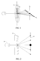
- FIG. 1 shows a schematic diagram of a transmission small-angel X-ray scattering (tSAXS) technique.
- tSAXS transmission small-angel X-ray scattering
- tSAXS has mostly been performed using the synchrotron X-ray source for its high beam flux or high brilliance.
- the scattering cross section of nanoscale features is intrinsically small due to their small scattering volume. With a feature size of 20 nm, for example, its height is typical 30 ⁇ 50 nm or about 2 times that of the feature size, its scattering volume is just the beam cross section times 30 ⁇ 50 nm, a minuscule value.
- Synchrotron X-ray sources have sufficient brilliance to overcome the abovementioned difficulty, however, they are simply too large and too expensive for daily industrial deployment.
- a lab system with a Molybdenum rotating anode X-ray source has been successfully demonstrated for this type of applications in National Institute of Standards and Technology (NIST), but the measurement speed is too slow for high volume manufacturing (HVM).
- HVM high volume manufacturing
- a recent development in X-ray source results in a liquid-metal jet source which can provide a significant increase in brilliance, and this is expected to result in an increase in measurement speed.
- increase in measurement speed is still not enough to enable tSAXS for HVM applications.
- the disclosure is to provide an apparatus for enhancing X-ray scattering intensity from a target object (the structures of interests).
- the enhancement of X-ray scattering intensity can lead to an increase in measurement speed as well as an improvement in signal quality.
- An X-ray beam irradiates on the gratings (structures) on Si wafer (or substrate) and a significant portion of the incident beam passes through the substrate with the scattered or diffracted beam moving toward the detector. Since wavelengths of the incident X-rays are much smaller than gratings (or structures), the X-rays can resolve the features of the gratings (structures) in many current and future IC generations. In light of the alignment of measurements in the tSAXS, the X-rays can either incident on gratings first, and the scattered X-rays pass through Si wafer (or substrate), or pass through Si wafer (or substrate) first, and scatter from the gratings (or structures).
- the scattered X-rays are detected by a spatially resolved detector.
- the pitch and pitch variation of the gratings can be obtained from major diffraction peaks and intensity decay with increasing order.
- the other geometric form factors such as SWA, LER, and LWR, are correlated with the envelope function of the diffraction intensities.
- SWA, LER, and LWR are correlated with the envelope function of the diffraction intensities.
- the measurements for CDs require many hours. While this time frame makes the technique useful as a research and development tool, significant throughput improvement is required to make the tSAXS practical to meet the grand challenges for in-line IC metrology applications.
- the X-ray source is a laboratory source, a synchrotron light source providing a high X-ray flux and many other X-ray sources.
- the disclosure provides an apparatus for amplifying scattering intensity from a target object 12 using an enhancement grating object 14 during tSAXS measurements.
- the words “scattering” and “diffraction” are used interchangeably; moreover, the phase of “amplify or enhance scattering intensity” does not necessarily imply that the scattering intensity at certain angles from a target object is increased literally.
- the enhancement of the scattering intensity or signal from a target object often manifests itself by a significantly decrease or increase in the scattering intensity from the background scattering intensities arisen from an enhancement object. In essence, it is the scattering signals or contributions from the target object becoming more discernable by applying the technique described in this disclosure; the contribution of scattering intensity from the target object can either be positive or negative.
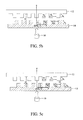
- FIG. 2 shows that the tSAXS is applied for measuring a patterned target object (shown in one-dimension).
- the X-ray scattered pattern can be measured by the spatially resolved detector 16, as shown in FIG. 2 .
- the scattering intensity from the target object 12 can be described as: I ⁇ ⁇ ⁇ b 1 2 ⁇ F 1 2 q where ⁇ ⁇ b 1 2 is a contrast factor of the target object 12 and its value is rather small in most nanoscale patterns.
- F 1 ( q ) is the Fourier transform of the target object and q is defined in its typical way as (4 ⁇ /)sin ⁇ , where ⁇ denotes the X-ray wavelength and ⁇ is the scattering angle.
- both the target and the enhancement objects are symmetric about their origin, hence all F(q) are real in value, i.e. with no imaginary component.
- An additional pattern (i.e., the enhancement grating object 14) with strong scattering cross section, as shown in FIG. 3a , is added into the path of the transmitted SAXS in between the target object 12 and the detector 16, as shown in FIG. 3b .
- the solid dots represent the positions of the peak intensities that refracted by the target object 12
- the grid shadings represent the positions of the peak intensities that refracted by the enhancement grating object 14.
- the screen tones i.e. the overlapping portion of the solid dots and the grid shadings, represent the positions of the peak intensities that refracted by the target object 12 and the enhancement grating object 14.
- the enhancement grating object 14 will be positioned in between the X-ray source and the target object 12, as shown in FIG. 3c . Both configurations provide the same enhancement for the X-ray intensity received by the X-ray detector 16.
- An apparatus for amplifying scattering intensity during tSAXS measurements includes: an enhancement grating object 14 positioned within a longitudinal coherence length of a incident X-ray from a target object 12; and a placement mechanism capable of placing the enhancement grating object 14 with nanometer precision with respect to the target object 12 in both a lateral and a longitudinal directions.
- the enhancement grating object is positioned either at a back of the target object or at a front of the target object, as shown in FIG. 3b and 3c .
- the enhancement grating object 14 is configured to be shifted laterally or longitudinally with respect to the target object with nanometer precision during tSAXS measurements.
- the enhancement grating object 14 is used as a reference object to facilitate critical dimension (CD) characterization of the target object with a single or multiple layered structure.
- the enhancement grating object 14 is a one-dimensional (1-D) grating object, a two-dimensional (2-D) grating object, arrays of holes, pillars and other periodical structures.
- the strong scattering object i.e., the enhancement grating object
- the strong scattering object is positioned within the longitudinal coherence length ⁇ of the X-rays of the weak scattering object, as shown in FIG. 3b-c .
- the observed scattering intensity becomes I q ⁇ ⁇ ⁇ b 1 ⁇ F 1 q + ⁇ ⁇ b 2 ⁇ F 2 q 2
- the second grating object denotes the enhancement grating object 14 with a strong scattering for intensity enhancement.
- Eq. (2) can be expended as follows: ⁇ ⁇ b 1 2 ⁇ F 1 2 q + ⁇ ⁇ b 2 2 ⁇ F 2 2 q + 2 ⁇ ⁇ ⁇ b 1 ⁇ ⁇ ⁇ b 2 F 1 q ⁇ F 2 q where 2 ⁇ b 1 ⁇ b 2
- carries information of the target object 12, and its magnitude can be significantly greater than ⁇ b 1 2 ⁇ F 1 2 ( q ) alone, since the value of ⁇ ⁇ b 2 2 and F 2 2 q can be much greater than those of the target object 12.
- the enhancement to different extent in the X-ray scattering intensity can be achieved by varying the physical dimensions and materials of the enhancement grating object 14.
- the preferred wavelengths of the X-rays are around 0.1 nm or smaller.
- w denotes the width of an individual line
- d is the pitch of grating
- n i is the order of the scattering peak.
- the height h of the line does not appear explicitly since its value is included in the contrast factor ⁇ b as ⁇ b ⁇ h x ⁇ , where ⁇ is the electron density of the grating material, and is defined as the total number of electrons within unit volume.
- ⁇ is the electron density of the grating material, and is defined as the total number of electrons within unit volume.
- ⁇ is the electron density of the grating material, and is defined as the total number of electrons within unit volume.
- ⁇ is the electron density of the grating material, and is defined as the total number of electrons within unit volume.
- ⁇ is the electron density of the grating material, and is defined as the total number of electrons within unit volume.
- Polystyrene is included to represent typical photoresists.
- the scattering intensity is proportional to the second power of F i ( q x ), thus, its value will decrease as n -2 as indicated by Eq. (4).
- Eq. (3) depicts a perfect alignment between the enhancement grating object 14 and the target object 12 as illustrated in FIG. 4a .
- ⁇ by definition, has to be less than or equal to d 1 /2, where d 1 denotes the pitch of the target object 12.
- the value of ⁇ b 2 is greater than that of ⁇ b 1 by choosing a high electron density material and a tall line height; i.e., with both ⁇ 1 > ⁇ 2 and h 2 > h 1 whenever it is possible.
- ⁇ b i is proportional to the product of ⁇ i and h i .
- the first term of Eq. (3") represents amplification of the observed scattering intensity by the interaction between the target object 12 and the enhancement grating object 14. It is important to properly control the value of ⁇ , such that the magnitude of 2cos( q x ⁇ ) F 1 ( q x ) F 2 ( q x ) is much greater than F 1 2 ( q x ) alone, whereas and the sign of the former term is often immaterial.
- n 2 ⁇ ⁇ n 1 .
- both the target object 12 and the enhancement grating object 14 can be aligned with a shift ⁇ in the x-direction.
- Table 1 summarizes the peak intensities under cases (I)-(V) and others.
- the aforesaid five cases demonstrate that the details of the amplification depend on the alignment of the enhancement grating object 14 with respect to the target object 12.
- the type of sensitivity provides a possible experimental route to quantify the extent of amplification when the value of ⁇ is swiped with a step less than a fraction of d 1 .
- the intensity enhancement of the target object 12 depends on the alignment in the x-direction. Once in the perfect alignment, the peak intensity can be up to 4 times for all the peaks. When the alignment starts to shift from 0 to d 1 4 (half of the line width), the intensity drops to 2 times for all the odd number peaks.
- embodiment 2 The conditions of embodiment 2 are the same with those of embodiment 1.
- the target object 12 is made of Si
- the enhancement grating object is made of Cu, as shown in FIG. 6 .
- Table 1 Intensities of each peak under cases (I)-(V) and others.
- the electron intensity of the enhancement grating object is f ⁇ 3.42 times that of the target object 12.
- the conditions of embodiment 4 are the same with those of embodiment 1.
- the scattering intensity overlaps at n 2 3 n 1 , i.e., the 3 rd peak of the enhancement grating object interacts with the 1 st peak of the target object 12 and so on.
- embodiments 1-4 amply demonstrate that the product of the grating height and the electron density (i.e., the factor f ), the alignment between the target object 12 and the enhancement grating object 14, the pitch and its ratio to line width affect the extent of intensity amplification of the target object 12.
- the target object 12 is made of Si, but the enhancement grating object 14 is made of Cu.
- the pattern part of the enhancement grating object 14 is made of materials with a high electron density such as copper, silver, gold and others.
- the magnitudes of three terms of Eq. (3") are as follows: F 1 2 q x F 2 2 q x ⁇ 34.2 2 3 ⁇ n 1 2 ⁇ sin 3 ⁇ n 1 ⁇ ⁇ m 2 sin n 1 ⁇ ⁇ m 2 ⁇ F 1 2 q x ⁇ 130 ⁇ F 1 2 q x 2 ⁇ f ⁇ cos q x ⁇ ⁇ ⁇ F 1 q x ⁇ F 2 q x ⁇ 2 ⁇ 34.2 3 ⁇ cos q x ⁇ ⁇ ⁇ sin 3 ⁇ n 1 ⁇ ⁇ 2 sin n 1 ⁇ ⁇ 2 ⁇ F 1 2 q x ⁇ - 23 ⁇ cos q x ⁇ ⁇ ⁇ F 1 2 q x for all the odd numbers n 1 , and nil for the rest.
- the scattering intensities at all the odd number peaks decrease by 23 F 1 2 ( q x ).
- the value of cos( q x ⁇ ) approaches -1 for all the intensities of all the odd number peaks and the value of cos ( q x ⁇ ) approaches -1 for the 3 rd and the 9 th peak positions as ⁇ ⁇ d 1 6 while cos( q x ⁇ ) approaches 0.5 for n 1 1, 3 and etc.
- the pattern part of the enhancement grating object 14 is "facing" the pattern part of the target object 12 for the purpose of ensuring these two patterned parts within the coherence length of the probing X-ray (or light) beams. This configuration minimizes the distance between the target object 12 and the enhancement grating object 14.
- the target object 12 is made of Si
- the enhancement grating object 14 is made of Cu.
- the 2 nd , 4 th , 6 th ... peaks of the target object 12 overlap with the 1 st , 2 nd , 3 rd , ... peaks of the enhancement grating object 14.
- the intensity enhancement for the target object 12 takes place at its 2 nd , 4 th , 6 th peaks. Even with an enhancement factor of 14, the observed intensity at the 2 nd peak is not going to be much higher than that of the first peak over which there is no amplification. In general, the intensity of the first peak is much greater than the rest and it is desirable to design an enhancement object capable to amplify the intensity of the first peak from the target object.
- the intensity enhancement may be further increased if the pitch height of the enhancement grating object 14 is larger than that of the target object 12.
- the target object 12 is made of Si
- the enhancement grating object is made of Cu.
- embodiments 1-7 are only used to exemplify the apparatus for enhancing scattering intensity using the tSAXS technique, and should not be construed as to limit the disclosure.
- the above embodiments of the disclosure can be modified and altered by those with ordinary skill in the art, without departing from the spirit and scope of the disclosure as defined in the following appended claims.
- the disclosure provides an apparatus for amplifying scattering intensities from a target object during X-ray scattering measurements.
- the measurement speed and signal quality are improved due to amplification of X-ray scattering.
- the analyses of critical dimension evaluations, shapes and variations in pitches can be facilitated when HVM is performed.
- the resulting apparatus for enhancement scattering intensity of the disclosure is cost-effective, uncomplicated, highly versatile and effective, and can be implemented by adopting known semiconductor technology for efficient and economical manufacturing, application and utilization. It valuably supports and services the trend of reducing costs, simplifying systems, and increasing performance.
Landscapes
- Chemical & Material Sciences (AREA)
- Biochemistry (AREA)
- Physics & Mathematics (AREA)
- Health & Medical Sciences (AREA)
- Life Sciences & Earth Sciences (AREA)
- Analytical Chemistry (AREA)
- Crystallography & Structural Chemistry (AREA)
- General Health & Medical Sciences (AREA)
- General Physics & Mathematics (AREA)
- Immunology (AREA)
- Pathology (AREA)
- Analysing Materials By The Use Of Radiation (AREA)
- Length-Measuring Devices Using Wave Or Particle Radiation (AREA)
- Diffracting Gratings Or Hologram Optical Elements (AREA)
Abstract
Description
- All related applications are incorporated by reference.
- The application is based on, and claims priority from,
U.S. Provisional Application Serial Number 61/891,062, filed on October 15, 2013 U.S. Non-Provisional Application Serial number 14/246,702, filed on April 7, 2014 - The technical field relates to an apparatus for amplifying intensity during transmission small angle X-ray scattering measurements.
- Transmission SAXS (tSAXS) has been identified as a potential solution for measuring nanoscale features by interrogating structures with sub-nanometer wavelength X-ray radiation. Most relevant parameters describing critical dimensions (CDs) of nanoscale features are pitch, pitch variations, side wall angle, line edge roughness, line width roughness and so forth. Based on the spacing of diffraction peaks, the parameter (pitch) can be extracted from the tSAXS scattering pattern. The geometric form factors of a structure can be extracted from the envelope function of the scattering intensity. In addition to the CDs of a structure, tSAXS has been used to successfully characterize LER, pitch walk, non-planar film thicknesses on sidewalls and complicated profiles of a memory structure that requires a 6-trapezoid model. Since the X-ray wavelength is still much smaller than the feature size of today's nanoscale structure, the tSAXS technique will stay as a viable CD metrology in the future. Actually the applicability of tSAXS will improve at future technology nodes where more densely packed features or an ever decreasing pitch will result in widely apart scattering peaks; thus, more readily detectable via tSAXS. Additionally, it avoids the issues related to optical properties, e.g. n and k, their wavelength and size dependences since tSAXS is based on classical X-ray elastic scattering, the observed scattering intensity depends only on variation in local electron density.
- The disclosure provides an apparatus for amplifying scattering intensity during tSAXS measurements. The apparatus includes an enhancement grating object and a placement mechanism. The enhancement grating object is positioned within a longitudinal coherence length of an incident X-ray from a target object. The placement mechanism is capable of placing the enhancement grating object with nanometer precision with respect to the target object in both a lateral and a longitudinal directions.
- The disclosure can be more fully understood by reading the following detailed description of the preferred embodiments/examples, with references made to the accompanying drawings, wherein:
-
FIG. 1 is a schematic diagram depicting a transmission small-angel X-ray scattering (tSAXS) system. The collimation part of the system located between the X-ray source and the sample is not shown. -
FIG. 2 is a schematic diagram depicting the tSAXS measurement for a target object (one-dimensional (1-D) grating) according to one exemplary embodiment of the disclosure. -
FIG. 3a is a schematic diagram illustrating the tSAXS measurement for an enhancement grating object (1-D grating) according to one exemplary embodiment of the disclosure. -
FIG. 3b is a schematic diagram illustrating the tSAXS measurement for the increase of the X-ray scattering intensity at the third and the sixth peaks from the target object according to one exemplary embodiment of the disclosure. -
FIG. 3c is a schematic diagram illustrating the tSAXS measurement for the increase of the X-ray scattering intensity at the third and the sixth peaks from the target object according to anther embodiment of the disclosure. -
FIG. 4a is a schematic diagram illustrating the tSAXS measurement including a target object and an enhancement grating object when h 2 = h 1, d 2 = d 1 and w 2 = w 1 in perfect alignment according to the disclosure. -
FIG. 4b is a schematic diagram illustrating a target object and an enhancement grating object when h 2 = h 1, d 2 = d 1 and w 2 = w 1 with a lateral shift η in the relative position between these two objects according to the disclosure. -
FIG. 5a is a schematic diagram illustrating identical materials for both the target object and the enhancement grating object with f = 1, α = 1 , m 1 = m 2 = 2 and η = 0 , the above conditions lead to cos(q x η) =1 according to the disclosure. -
FIG. 5b is a schematic diagram illustrating identical materials for both the target object and the enhancement grating object with f = 1, a = 1, m 1 = m 2 = 2 and
-
FIG. 5c is a schematic diagram illustrating identical materials for both the target object and the enhancement grating object with f = 1, a =1 , m 1 = m 2 = 2 and
-
FIG. 6 is a schematic diagram illustrating the enhancement grating object made of Cu and the target object made of Si in perfect alignment when η = 0 according to the disclosure. -
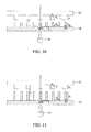
FIG. 7 is a schematic diagram illustrating identical materials for both the target object and the enhancement grating object when h2 = 10h 1 for f =10 in perfect alignment (η=0) according to the disclosure. -
FIG. 8 is a schematic diagram illustrating identical materials for both the target object and the enhancement grating object when d 2 = 3d 1 in perfect alignment (η = 0) according to the disclosure. -
FIG. 9 is a schematic diagram illustrating the enhancement grating object made of Cu and the target object made of Si with m 1 = m 2 when h 2 = 10h 1 and d 2 = 3d 1 according to the disclosure. -
FIG. 10 is a schematic diagram illustrating the enhancement grating object made of Cu and the target object made of Si when h 2 = h 1 and
-
FIG. 11 is a schematic diagram illustrating the enhancement grating object made of Cu and the target object made of Si when h1 = 5h 2 and
- The following embodiments are described in sufficient detail to enable those skilled in the art to make and use the disclosure. It is to be understood that other embodiments would be evident based on the disclosure, and that system or mechanical changes may be made without departing from the scope of the disclosure.
- In the following description, numerous specific details are given to provide a thorough understanding of the disclosure. However, it will be apparent that the disclosure may be practiced without these specific details. In order to avoid obscuring the disclosure, some well-known mechanisms and system configurations are not disclosed in detail.
- The drawings showing embodiments of the architecture are semi-diagrammatic and not to scale and, particularly, some of the dimensions are for clarity of presentation and are shown exaggerated in the drawings. Similarly, although the views in the drawings for ease of description generally show similar orientations, this depiction in the drawings is arbitrary for the most part. Generally, the disclosure can be operated in any orientation.
- The disclosure is described by the following specific embodiments and examples. Those with ordinary skills in the arts can readily understand the other functions of the disclosure after reading the disclosure of this specification. The disclosure can also be implemented with different embodiments and examples. Various details described in this specification can be modified based on different viewpoints and applications without departing from the scope of the disclosure.
-
FIG. 1 shows a schematic diagram of a transmission small-angel X-ray scattering (tSAXS) technique. - tSAXS has mostly been performed using the synchrotron X-ray source for its high beam flux or high brilliance. The scattering cross section of nanoscale features is intrinsically small due to their small scattering volume. With a feature size of 20 nm, for example, its height is typical 30 ~ 50 nm or about 2 times that of the feature size, its scattering volume is just the beam cross section times 30 ~50 nm, a minuscule value. Synchrotron X-ray sources have sufficient brilliance to overcome the abovementioned difficulty, however, they are simply too large and too expensive for daily industrial deployment. A lab system with a Molybdenum rotating anode X-ray source has been successfully demonstrated for this type of applications in National Institute of Standards and Technology (NIST), but the measurement speed is too slow for high volume manufacturing (HVM). A recent development in X-ray source results in a liquid-metal jet source which can provide a significant increase in brilliance, and this is expected to result in an increase in measurement speed. However, such increase in measurement speed is still not enough to enable tSAXS for HVM applications. The disclosure is to provide an apparatus for enhancing X-ray scattering intensity from a target object (the structures of interests). The enhancement of X-ray scattering intensity can lead to an increase in measurement speed as well as an improvement in signal quality.
- An X-ray beam irradiates on the gratings (structures) on Si wafer (or substrate) and a significant portion of the incident beam passes through the substrate with the scattered or diffracted beam moving toward the detector. Since wavelengths of the incident X-rays are much smaller than gratings (or structures), the X-rays can resolve the features of the gratings (structures) in many current and future IC generations. In light of the alignment of measurements in the tSAXS, the X-rays can either incident on gratings first, and the scattered X-rays pass through Si wafer (or substrate), or pass through Si wafer (or substrate) first, and scatter from the gratings (or structures). Either way, the scattered X-rays (or diffracted X-rays) are detected by a spatially resolved detector. The pitch and pitch variation of the gratings can be obtained from major diffraction peaks and intensity decay with increasing order. The other geometric form factors, such as SWA, LER, and LWR, are correlated with the envelope function of the diffraction intensities. However, due to the limitation of the X-ray intensity or flux provided by the laboratory X-ray source, the measurements for CDs require many hours. While this time frame makes the technique useful as a research and development tool, significant throughput improvement is required to make the tSAXS practical to meet the grand challenges for in-line IC metrology applications.
- The X-ray source is a laboratory source, a synchrotron light source providing a high X-ray flux and many other X-ray sources.
- In order to increase the throughput for high volume manufacturing (HVM), the detectable X-ray scattering intensity or intensity envelop function of diffraction patterns are also required to shorten the collection time. Accordingly, the disclosure provides an apparatus for amplifying scattering intensity from a
target object 12 using anenhancement grating object 14 during tSAXS measurements. - Throughout this disclosure the words "scattering" and "diffraction" are used interchangeably; moreover, the phase of "amplify or enhance scattering intensity" does not necessarily imply that the scattering intensity at certain angles from a target object is increased literally. As to be demonstrated in the forthcoming embodiments of the disclosure, the enhancement of the scattering intensity or signal from a target object often manifests itself by a significantly decrease or increase in the scattering intensity from the background scattering intensities arisen from an enhancement object. In essence, it is the scattering signals or contributions from the target object becoming more discernable by applying the technique described in this disclosure; the contribution of scattering intensity from the target object can either be positive or negative.
-
FIG. 2 shows that the tSAXS is applied for measuring a patterned target object (shown in one-dimension). The X-ray scattered pattern can be measured by the spatially resolveddetector 16, as shown inFIG. 2 . - According to the disclosure, the scattering intensity from the target object 12 (grating) can be described as:


target object 12 and its value is rather small in most nanoscale patterns. F 1(q) is the Fourier transform of the target object and q is defined in its typical way as (4π/)sinθ, where λ denotes the X-ray wavelength and θ is the scattering angle. Throughout this disclosure both the target and the enhancement objects are symmetric about their origin, hence all F(q) are real in value, i.e. with no imaginary component. - An additional pattern (i.e., the enhancement grating object 14) with strong scattering cross section, as shown in
FIG. 3a , is added into the path of the transmitted SAXS in between thetarget object 12 and thedetector 16, as shown inFIG. 3b . As shown inFig. 3b , the solid dots represent the positions of the peak intensities that refracted by thetarget object 12, and the grid shadings represent the positions of the peak intensities that refracted by theenhancement grating object 14. The screen tones, i.e. the overlapping portion of the solid dots and the grid shadings, represent the positions of the peak intensities that refracted by thetarget object 12 and theenhancement grating object 14. In practice or in the application of semiconductor industry in-line measurements, theenhancement grating object 14 will be positioned in between the X-ray source and thetarget object 12, as shown inFIG. 3c . Both configurations provide the same enhancement for the X-ray intensity received by theX-ray detector 16. - An apparatus for amplifying scattering intensity during tSAXS measurements, includes: an
enhancement grating object 14 positioned within a longitudinal coherence length of a incident X-ray from atarget object 12; and a placement mechanism capable of placing theenhancement grating object 14 with nanometer precision with respect to thetarget object 12 in both a lateral and a longitudinal directions. - The enhancement grating object is positioned either at a back of the target object or at a front of the target object, as shown in
FIG. 3b and 3c . - The
enhancement grating object 14 is configured to be shifted laterally or longitudinally with respect to the target object with nanometer precision during tSAXS measurements. - The
enhancement grating object 14 is used as a reference object to facilitate critical dimension (CD) characterization of the target object with a single or multiple layered structure. - The
enhancement grating object 14 is a one-dimensional (1-D) grating object, a two-dimensional (2-D) grating object, arrays of holes, pillars and other periodical structures. - Upon the weak scattering object (i.e., the target object 12), the strong scattering object (i.e., the enhancement grating object) is positioned within the longitudinal coherence length ε of the X-rays of the weak scattering object, as shown in
FIG. 3b-c . The observed scattering intensity becomes
enhancement grating object 14 with a strong scattering for intensity enhancement. - Eq. (2) can be expended as follows:

enhancement grating object 14 and thetarget object 12. The interaction term 2Δb 1Δb 2 |F 1(q)F 2 (q) | carries information of thetarget object 12, and its magnitude can be significantly greater than Δb 1 2 × F 1 2(q) alone, since the value of

target object 12. - Regarding the
enhancement grating object 14 positioned within the longitudinal coherence length ε with thetarget object 12, the enhancement to different extent in the X-ray scattering intensity can be achieved by varying the physical dimensions and materials of theenhancement grating object 14. For semiconductor manufacture applications, the preferred wavelengths of the X-rays are around 0.1 nm or smaller. - In the following embodiments, both the
target object 12 and theenhancement grating object 14 are line gratings with rectangular cross section lines. As shown inFIG. 2 andFIG. 3a , all the diffraction spots are appeared along qx with qy = 0. The function Fi (q) can be replaced by Fi (qx ), and can be explicitly expressed as:
- Also, Eq. (3) depicts a perfect alignment between the
enhancement grating object 14 and thetarget object 12 as illustrated inFIG. 4a . In view of a misalignment or a lateral shift by η, Eq. (3) is changed to:
- The value of η, by definition, has to be less than or equal to d1 /2, where d 1 denotes the pitch of the
target object 12. - Preferably, the value of Δb 2 is greater than that of Δb 1 by choosing a high electron density material and a tall line height; i.e., with both ρ1 > ρ2 and h 2 > h 1 whenever it is possible. Moreover, Δbi is proportional to the product of ρ i and hi.
The ratio of

- The first term of Eq. (3") represents amplification of the observed scattering intensity by the interaction between the
target object 12 and theenhancement grating object 14. It is important to properly control the value of η, such that the magnitude of 2cos(qx η)F 1(qx )F 2(qx ) is much greater than F 1 2(qx ) alone, whereas and the sign of the former term is often immaterial. - In order to realize certain amplification, the pitch of the enhancement grating object, d 2 has to follow the condition as d 2 = α × d 1, where α may be ...1/4,1/3,1/2,1, 2, 3, 4,... etc. Explicitly the conditions for certain amplification to be realized at a given qx are: (a) overlap of certain peak positions of two objects, or

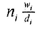
target object 12 is NOT an integer; otherwise, the intensity of the
- Since d2 can be expressed as a × d 1 , the condition (a) becomes n 2 = α × n 1. At a = 1, all the peak positions between these two grating objects overlap. When α = 2 , the 2nd peak of the
enhancement grating object 14 coincides with the first peak of thetarget object 12, the 4th peak of theenhancement grating object 14 coincides with the 2nd peak of thetarget object 12 and so on. Before amplification of the peak intensity of thetarget object 12 can be realized, the condition (b) indicates that the ratio

- When α =1/2,1/3,1/4, ... , the first order peak of the
target object 12 is no longer to be amplified, the 2nd, 3rd and 4th orders will get amplified by the first peak of theenhancement object 14 respectively as long as the condition (b) is fulfilled. - For a pair of


- The disclosure will be more specifically described by the followings embodiments. However, these embodiments are not intended to limit the scope of the disclosure.
- In
embodiment 1 of the disclosure, both thetarget object 12 andenhancement grating object 14 are identical in material and h 2=h 1, hence f =1. Moreover, d 2 = d1 , hence α = 1 . The line width is half of the pitch for both theenhancement grating object 14 and thetarget object 12, i.e., m 1 = m 2 = 2. - As shown in
FIG. 4b andFIG. 5 , both thetarget object 12 and theenhancement grating object 14 can be aligned with a shift η in the x-direction. The magnitudes of three terms of Eq. (3") are as follows:


- According to
embodiment 1 of the disclosure, Eq. (3") becomes:


- In case (I), qx η = 0 is required; that is, η = 0 or η → 0 . The alignment of the
target object 12 with theenhancement grating object 14 is perfect, as shown inFIG. 5a . For all the peak positions, the following equation can be obtained.

- In case (II), qx η = π/2 is required; that is,


FIG. 5b . Thus, for all the peak positions, the following equation can be obtained.

- In case (III), qx η = π is required; that is,


FIG. 5c . For all the peak positions, the following equation can be obtained.

- In case (IV),
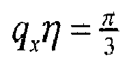


- In case (V),


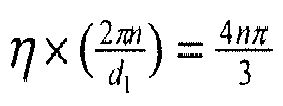


- According to the disclosure, Table 1 summarizes the peak intensities under cases (I)-(V) and others.
- The aforesaid five cases demonstrate that the details of the amplification depend on the alignment of the
enhancement grating object 14 with respect to thetarget object 12. The type of sensitivity provides a possible experimental route to quantify the extent of amplification when the value of η is swiped with a step less than a fraction of d 1. The intensity enhancement of thetarget object 12 depends on the alignment in the x-direction. Once in the perfect alignment, the peak intensity can be up to 4 times for all the peaks. When the alignment starts to shift from 0 to


- The conditions of embodiment 2 are the same with those of
embodiment 1. However, thetarget object 12 is made of Si, and the enhancement grating object is made of Cu, as shown inFIG. 6 .Table 1: Intensities of each peak under cases (I)-(V) and others. q η η ni , the order of scattering peak 1 2 3 4 5 6 7 8 9 10 0 0 4F 1 2 4F 1 2 4F 1 2 4F 1 2 4F 1 2 4F 1 2 4F 1 2 4F 1 2 4F 1 2 4F 1 2 

3F 1 2 1F 1 2 0 1F 1 2 3F 1 2 4F 1 2 3F 1 2 1F 1 2 0 1F 1 2 

2F 1 2 4F 1 2 2F 1 2 4F 1 2 2F 1 2 4F 1 2 2F 1 2 4F 1 2 2F 1 2 4F 1 2 

1F 1 2 1F1 2 4F 1 2 1F 1 2 1F 1 2 4F 1 2 1F 1 2 1F 1 2 4F 1 2 1F 1 2 π 
0 4F 1 2 0 4F 1 2 0 4F 1 2 0 4F 1 2 0 4F 1 2 

1F 1 2 1F 1 2 4F 1 2 1F 1 2 1F 1 2 4F 1 2 1F 1 2 1F 1 2 4F 1 2 1F 1 2 

2F 1 2 4F 1 2 2F 1 2 4F 1 2 2F 1 2 4F 1 2 2F 1 2 4F 1 2 2F 1 2 4F 1 2 

3F 1 2 1F 1 2 0 1F 1 2 3F 1 2 4F 1 2 3F 1 2 1F 1 2 0 1F 1 2 2π 0 4F 1 2 4F 1 2 4F 1 2 4F 1 2 4F 1 2 4F 1 2 4F 1 2 4F 1 2 4F 1 2 4F 1 2 - Since the enhancement grating object is made of Cu and the
target object 12 is made of Si, the electron intensity of the enhancement grating object is f~3.42 times that of thetarget object 12. - According to embodiment 2 of the disclosure, the magnitudes of three terms of Eq. (3") are as follows:


- The conditions of embodiment 3 are the same with those of
embodiment 1, but the feature height of the enhancement grating object is selected to be h 2 = 10h 1, i.e. f=10 and let the two objects having identical electron density, as shown inFIG. 7 , the magnitudes of three terms of Eq. (3") are as follows:




- The conditions of embodiment 4 are the same with those of
embodiment 1. The line width to pitch ratio is identical for these two objects, i.e.
Fig. 8 . Since both thetarget object 12 and theenhancement grating object 14 are identical in material and in grating height, i.e., f = 1. The scattering intensity overlaps at n 2 = 3n 1, i.e., the 3rd peak of the enhancement grating object interacts with the 1st peak of thetarget object 12 and so on. - According to embodiment 4 of the disclosure, the magnitudes of three terms of Eq. (3") are as follows:


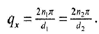
target object 12. - According to the disclosure, embodiments 1-4 amply demonstrate that the product of the grating height and the electron density (i.e., the factor f ), the alignment between the
target object 12 and theenhancement grating object 14, the pitch and its ratio to line width affect the extent of intensity amplification of thetarget object 12. - In embodiment 5 of the disclosure, the
target object 12 is made of Si, but theenhancement grating object 14 is made of Cu. Let h 2 = 10h 1 and d 2 = 3d 1, the line width is half of the pitch for both theenhancement grating object 14 and thetarget object 12, i.e. m 1 = m 2 = 2. The pattern part of theenhancement grating object 14 is made of materials with a high electron density such as copper, silver, gold and others. - In this embodiment, given f = 34.2, the positions qx are located at

- As such, according to embodiment 5 of the disclosure, the magnitudes of three terms of Eq. (3") are as follows:


- As in previous cases the value of cos(qx η) plays an important role in Eqs. (13a)-(13c). Considering the 3rd terms, it has a range between +23F 1 2(qx ) and - 23F 1 2(qx ).
- At η → 0 (i.e., zero misalignment between two objects), the scattering intensities at all the odd number peaks decrease by 23F 1 2(qx ). As

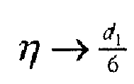
target object 12 with a magnitude between ±23F 1 2(qx ) can be observed. Accordingly, the results will facilitate the detection of 2 cos(qx η)F 1(qx )F 2(qx ) by scanning η between
enhancement grating object 14 is "facing" the pattern part of thetarget object 12 for the purpose of ensuring these two patterned parts within the coherence length of the probing X-ray (or light) beams. This configuration minimizes the distance between thetarget object 12 and theenhancement grating object 14. - In this embodiment, the
target object 12 is made of Si, and theenhancement grating object 14 is made of Cu. The heights of these two objects are the same; that is, h 2 = h 1 hence we have f = 3.42. The pitch of the enhancement grating object is
enhancement grating object 14 and thetarget object 12; that is, m 1 = m 2 = 3 , as shown inFIG. 10 . - The 2nd, 4th, 6th ... peaks of the
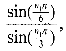
target object 12 overlap with the 1st, 2nd, 3rd, ... peaks of theenhancement grating object 14. In other words, the condition n 1 = 2n 2 indicates that n 1 has to be an even number. The condition m = 2 will lead to all the even number peaks to vanish, hence it is avoided in this embodiment. As such the magnitudes of three terms of Eq. (3") are as follows:

term 



- Moreover, it is important to note that the intensity enhancement for the
target object 12 takes place at its 2nd, 4th, 6th peaks. Even with an enhancement factor of 14, the observed intensity at the 2nd peak is not going to be much higher than that of the first peak over which there is no amplification. In general, the intensity of the first peak is much greater than the rest and it is desirable to design an enhancement object capable to amplify the intensity of the first peak from the target object. - The intensity enhancement may be further increased if the pitch height of the
enhancement grating object 14 is larger than that of thetarget object 12. For example, h 2 = 5h 1 and f = 17.1, as shown inFIG. 11 where thetarget object 12 is made of Si, and the enhancement grating object is made of Cu. With all the other feature dimensions identical to those of embodiment 6, the magnitudes of three terms of Eq. (3") are as follows:



- According to the disclosure, embodiments 1-7 are only used to exemplify the apparatus for enhancing scattering intensity using the tSAXS technique, and should not be construed as to limit the disclosure. As such, the above embodiments of the disclosure can be modified and altered by those with ordinary skill in the art, without departing from the spirit and scope of the disclosure as defined in the following appended claims.
- The foregoing description of the exemplary embodiments of the disclosure has been presented only for the purposes of illustration and description and is not intended to be exhaustive or to limit the disclosure to the precise forms disclosed. Many modifications and variations are possible in light of the above teaching. The embodiments were chosen and described in order to explain the principles of the disclosure, i.e. placing an object within the longitudinal coherence length of the target object to enhance the scattering signal from the target object, and their practical application so as to activate others skilled in the art to utilize the invention and various embodiments and with various modifications as are suited to the particular use contemplated.
- Therefore, the disclosure provides an apparatus for amplifying scattering intensities from a target object during X-ray scattering measurements. The measurement speed and signal quality are improved due to amplification of X-ray scattering. The analyses of critical dimension evaluations, shapes and variations in pitches can be facilitated when HVM is performed.
- Accordingly, solutions to the problems described above have been long sought, but prior developments have not taught or suggested any solutions and, thus, solutions to the problems have long eluded those skilled in the art. Therefore, there is a heretofore-unaddressed need to overcome deficiencies and shortcomings described above.
- The resulting apparatus for enhancement scattering intensity of the disclosure is cost-effective, uncomplicated, highly versatile and effective, and can be implemented by adopting known semiconductor technology for efficient and economical manufacturing, application and utilization. It valuably supports and services the trend of reducing costs, simplifying systems, and increasing performance.
- While the disclosure has been described in conjunction with a specific best mode, it is to be understood that many alternatives, modifications, and variations will be apparent to those skilled in the art in light of the aforesaid description. Accordingly, it is intended to embrace all such alternatives, modifications, and variations that fall within the scope of the included claims. All matters heretofore set forth herein or shown in the accompanying drawings are to be interpreted in an illustrative and non-limiting sense.
Claims (12)
- An apparatus for amplifying scattering intensity during transmission small-angle X-ray scattering (tSAXS) measurements, comprising:an enhancement grating object positioned within a longitudinal coherence length of an incident X-ray from a target object; anda placement mechanism capable of placing the enhancement grating object with nanometer precision with respect to the target object in both a lateral and a longitudinal directions.
- The apparatus according to claim 1, wherein the enhancement grating object is positioned either at a front of the target object or at a back of the target object.
- The apparatus according to claim 1 or 2, wherein a pattern part of the enhancement grating object faces a pattern part of the target object.
- The apparatus according to any one of claims 1 to 3, wherein the enhancement grating object is made of a material the same as or different from the target object.
- The apparatus according to any one of claims 1 to 4, wherein a height of a pattern part of the enhancement grating object is larger than a height of a pattern part of the target object by a factor greater than unity.
- The apparatus according to any one of claims 1 to 5, wherein a pitch of a pattern part of the enhancement grating object is a times larger than a pitch of a pattern part of the target object, or 1/α of a height of the pattern part of the target object, where α is an integer greater than or equal to unity.
- The apparatus according to any one of claims 1 to 6, wherein a pattern part of the enhancement grating object is made of materials with a high electron density such as copper, silver, gold and others.
- The apparatus according to any one of claims 1 to 7, wherein the enhancement grating object is configured to be shifted laterally with respect to the target object with nanometer precision during tSAXS measurements.
- The apparatus according to any one of claims 1 to 8, wherein the enhancement grating object is configured to be shifted longitudinally with respect to the target object with nanometer precision during tSAXS measurements.
- The apparatus according to any one of claims 1 to 9, wherein the enhancement grating object is used as a reference object to facilitate critical dimension (CD) characterization of the target object with a single or multiple layered structure.
- The apparatus according to any one of claims 1 to 10, wherein a source of the incident X-ray is a laboratory source, a synchrotron light source providing a high X-ray flux and many other X-ray sources.
- The apparatus according to any one of claims 1 to 11, wherein the enhancement grating object is a one-dimensional (1-D) grating object, a two-dimensional (2-D) grating object, arrays of holes, pillars and other periodical structures.
Applications Claiming Priority (2)
| Application Number | Priority Date | Filing Date | Title |
|---|---|---|---|
| US201361891062P | 2013-10-15 | 2013-10-15 | |
| US14/246,702 US9297772B2 (en) | 2013-07-30 | 2014-04-07 | Apparatus for amplifying intensity during transmission small angle—X-ray scattering measurements |
Publications (2)
| Publication Number | Publication Date |
|---|---|
| EP2863213A1 true EP2863213A1 (en) | 2015-04-22 |
| EP2863213B1 EP2863213B1 (en) | 2019-11-27 |
Family
ID=51730378
Family Applications (1)
| Application Number | Title | Priority Date | Filing Date |
|---|---|---|---|
| EP14188777.8A Active EP2863213B1 (en) | 2013-10-15 | 2014-10-14 | Apparatus for amplifying intensity during transmission small angle X-ray scattering measurements |
Country Status (4)
| Country | Link |
|---|---|
| EP (1) | EP2863213B1 (en) |
| JP (1) | JP6006768B2 (en) |
| CN (1) | CN104807841B (en) |
| TW (1) | TWI538565B (en) |
Cited By (1)
| Publication number | Priority date | Publication date | Assignee | Title |
|---|---|---|---|---|
| US10352694B2 (en) | 2017-04-18 | 2019-07-16 | Industrial Technology Research Institute | Contactless dual-plane positioning method and device |
Families Citing this family (5)
| Publication number | Priority date | Publication date | Assignee | Title |
|---|---|---|---|---|
| US10684238B2 (en) * | 2016-01-11 | 2020-06-16 | Bruker Technologies Ltd. | Method and apparatus for X-ray scatterometry |
| CN107589134B (en) * | 2016-07-08 | 2019-10-01 | 中国科学院化学研究所 | A kind of two-dimensional scattering spectrum calculation method and system based on SAXS technology |
| CN107976843B (en) * | 2018-01-25 | 2021-11-02 | 京东方科技集团股份有限公司 | Phase difference layer, display panel and display device |
| JP7168985B2 (en) | 2019-04-22 | 2022-11-10 | 株式会社リガク | Microstructure analysis method, device and program |
| JP7100897B2 (en) | 2019-04-22 | 2022-07-14 | 株式会社リガク | Ultrastructure analysis methods, equipment and programs |
Citations (2)
| Publication number | Priority date | Publication date | Assignee | Title |
|---|---|---|---|---|
| WO1998033062A1 (en) * | 1997-01-24 | 1998-07-30 | Quanta Vision, Inc. | Inspection equipment using small-angle topography in determining an object's internal structure and composition |
| WO2011096584A1 (en) * | 2010-02-04 | 2011-08-11 | Fujifilm Corporation | Radiation imaging system |
Family Cites Families (5)
| Publication number | Priority date | Publication date | Assignee | Title |
|---|---|---|---|---|
| JP3519208B2 (en) * | 1996-03-29 | 2004-04-12 | 理学電機株式会社 | X-ray small-angle scattering device with vacuum chamber |
| EP1879020A1 (en) * | 2006-07-12 | 2008-01-16 | Paul Scherrer Institut | X-ray interferometer for phase contrast imaging |
| US9269471B2 (en) * | 2009-03-27 | 2016-02-23 | Koninklijke Philips N.V. | Differential phase-contrast imaging with circular gratings |
| WO2011011014A1 (en) * | 2009-07-24 | 2011-01-27 | The United States Of America, As Represented By The Secretary, Department Of Health And Human Services | X-ray scattering imaging |
| JP5150713B2 (en) * | 2010-12-08 | 2013-02-27 | 富士フイルム株式会社 | Radiation image detection device, radiation imaging device, radiation imaging system |
-
2014
- 2014-10-14 TW TW103135467A patent/TWI538565B/en active
- 2014-10-14 EP EP14188777.8A patent/EP2863213B1/en active Active
- 2014-10-15 JP JP2014211199A patent/JP6006768B2/en active Active
- 2014-10-15 CN CN201410544535.5A patent/CN104807841B/en active Active
Patent Citations (2)
| Publication number | Priority date | Publication date | Assignee | Title |
|---|---|---|---|---|
| WO1998033062A1 (en) * | 1997-01-24 | 1998-07-30 | Quanta Vision, Inc. | Inspection equipment using small-angle topography in determining an object's internal structure and composition |
| WO2011096584A1 (en) * | 2010-02-04 | 2011-08-11 | Fujifilm Corporation | Radiation imaging system |
Non-Patent Citations (1)
| Title |
|---|
| WANG C ET AL: "Small angle X-ray scattering measurements of spatial dependent linewidth in dense nanoline gratings", THIN SOLID FILMS, ELSEVIER-SEQUOIA S.A. LAUSANNE, CH, vol. 517, no. 20, 31 August 2009 (2009-08-31), pages 5844 - 5847, XP027077206, ISSN: 0040-6090, [retrieved on 20090316], DOI: 10.1016/J.TSF.2009.03.040 * |
Cited By (1)
| Publication number | Priority date | Publication date | Assignee | Title |
|---|---|---|---|---|
| US10352694B2 (en) | 2017-04-18 | 2019-07-16 | Industrial Technology Research Institute | Contactless dual-plane positioning method and device |
Also Published As
| Publication number | Publication date |
|---|---|
| CN104807841B (en) | 2018-01-26 |
| CN104807841A (en) | 2015-07-29 |
| TWI538565B (en) | 2016-06-11 |
| TW201515517A (en) | 2015-04-16 |
| EP2863213B1 (en) | 2019-11-27 |
| JP6006768B2 (en) | 2016-10-12 |
| JP2015078988A (en) | 2015-04-23 |
Similar Documents
| Publication | Publication Date | Title |
|---|---|---|
| EP2863213B1 (en) | Apparatus for amplifying intensity during transmission small angle X-ray scattering measurements | |
| US9297772B2 (en) | Apparatus for amplifying intensity during transmission small angle—X-ray scattering measurements | |
| Pauw | Everything SAXS: small-angle scattering pattern collection and correction | |
| US10060865B2 (en) | Measurement of critical dimensions of nanostructures using X-ray grazing incidence in-plane diffraction | |
| Jiang | GIXSGUI: a MATLAB toolbox for grazing-incidence X-ray scattering data visualization and reduction, and indexing of buried three-dimensional periodic nanostructured films | |
| Neuwirth et al. | A high visibility Talbot-Lau neutron grating interferometer to investigate stress-induced magnetic degradation in electrical steel | |
| TWI421642B (en) | Overlay metrology using x-rays | |
| US20100327175A1 (en) | Phase-contrast imaging method and apparatus | |
| US20140233699A1 (en) | Phase imaging | |
| Chabior et al. | Signal-to-noise ratio in x ray dark-field imaging using a grating interferometer | |
| Punegov | High-resolution X-ray diffraction in crystalline structures with quantum dots | |
| Dahal et al. | Characterization of materials embedded in thick objects using spectral small-angle X-ray scattering | |
| Uehara et al. | Effectiveness of X-ray grating interferometry for non-destructive inspection of packaged devices | |
| Ando et al. | Improving contrast and spatial resolution in crystal analyzer‐based x‐ray dark‐field imaging: Theoretical considerations and experimental demonstration | |
| Nowak et al. | Geometrical optics modelling of grazing incidence X-ray fluorescence of nanoscaled objects | |
| Strobl et al. | Differential phase contrast and dark field neutron imaging | |
| Rieske et al. | Novel method for crystal defect analysis of laser drilled TSVs | |
| Molodkin et al. | Dynamical effects in the integrated X-ray scattering intensity from imperfect crystals in Bragg diffraction geometry. II. Dynamical theory | |
| CN100416223C (en) | Synchrotron Radiation Monochromator Crystal Thermal Expansion Deformation Detection Method | |
| Dąbrowski et al. | Laboratory-based recording of holographic fine structure in X-ray absorption anisotropy using polycapillary optics | |
| JP3422289B2 (en) | X-ray phase contrast imaging device | |
| Kazimirov et al. | Microbeam high-resolution diffraction and x-ray standing wave methods applied to semiconductor structures | |
| Frenkel | Two views at strained nanocrystals from the opposite sides of spatial resolution limit | |
| Hönicke et al. | Reference-free x-ray fluorescence analysis with a micrometer-sized incident beam | |
| Zaka | Energy resolution improvement of a laboratory scale X-ray absorption spectrometer using a position-sensitive detector |
Legal Events
| Date | Code | Title | Description |
|---|---|---|---|
| PUAI | Public reference made under article 153(3) epc to a published international application that has entered the european phase |
Free format text: ORIGINAL CODE: 0009012 |
|
| 17P | Request for examination filed |
Effective date: 20141014 |
|
| AK | Designated contracting states |
Kind code of ref document: A1 Designated state(s): AL AT BE BG CH CY CZ DE DK EE ES FI FR GB GR HR HU IE IS IT LI LT LU LV MC MK MT NL NO PL PT RO RS SE SI SK SM TR |
|
| AX | Request for extension of the european patent |
Extension state: BA ME |
|
| R17P | Request for examination filed (corrected) |
Effective date: 20151020 |
|
| RBV | Designated contracting states (corrected) |
Designated state(s): AL AT BE BG CH CY CZ DE DK EE ES FI FR GB GR HR HU IE IS IT LI LT LU LV MC MK MT NL NO PL PT RO RS SE SI SK SM TR |
|
| 17Q | First examination report despatched |
Effective date: 20160316 |
|
| STAA | Information on the status of an ep patent application or granted ep patent |
Free format text: STATUS: EXAMINATION IS IN PROGRESS |
|
| GRAP | Despatch of communication of intention to grant a patent |
Free format text: ORIGINAL CODE: EPIDOSNIGR1 |
|
| STAA | Information on the status of an ep patent application or granted ep patent |
Free format text: STATUS: GRANT OF PATENT IS INTENDED |
|
| INTG | Intention to grant announced |
Effective date: 20190405 |
|
| GRAS | Grant fee paid |
Free format text: ORIGINAL CODE: EPIDOSNIGR3 |
|
| GRAJ | Information related to disapproval of communication of intention to grant by the applicant or resumption of examination proceedings by the epo deleted |
Free format text: ORIGINAL CODE: EPIDOSDIGR1 |
|
| GRAL | Information related to payment of fee for publishing/printing deleted |
Free format text: ORIGINAL CODE: EPIDOSDIGR3 |
|
| STAA | Information on the status of an ep patent application or granted ep patent |
Free format text: STATUS: EXAMINATION IS IN PROGRESS |
|
| INTC | Intention to grant announced (deleted) | ||
| GRAP | Despatch of communication of intention to grant a patent |
Free format text: ORIGINAL CODE: EPIDOSNIGR1 |
|
| STAA | Information on the status of an ep patent application or granted ep patent |
Free format text: STATUS: GRANT OF PATENT IS INTENDED |
|
| INTG | Intention to grant announced |
Effective date: 20190925 |
|
| GRAA | (expected) grant |
Free format text: ORIGINAL CODE: 0009210 |
|
| STAA | Information on the status of an ep patent application or granted ep patent |
Free format text: STATUS: THE PATENT HAS BEEN GRANTED |
|
| AK | Designated contracting states |
Kind code of ref document: B1 Designated state(s): AL AT BE BG CH CY CZ DE DK EE ES FI FR GB GR HR HU IE IS IT LI LT LU LV MC MK MT NL NO PL PT RO RS SE SI SK SM TR |
|
| REG | Reference to a national code |
Ref country code: GB Ref legal event code: FG4D |
|
| REG | Reference to a national code |
Ref country code: CH Ref legal event code: EP |
|
| REG | Reference to a national code |
Ref country code: DE Ref legal event code: R096 Ref document number: 602014057403 Country of ref document: DE |
|
| REG | Reference to a national code |
Ref country code: AT Ref legal event code: REF Ref document number: 1207267 Country of ref document: AT Kind code of ref document: T Effective date: 20191215 |
|
| REG | Reference to a national code |
Ref country code: IE Ref legal event code: FG4D |
|
| REG | Reference to a national code |
Ref country code: NL Ref legal event code: FP |
|
| REG | Reference to a national code |
Ref country code: LT Ref legal event code: MG4D |
|
| PG25 | Lapsed in a contracting state [announced via postgrant information from national office to epo] |
Ref country code: ES Free format text: LAPSE BECAUSE OF FAILURE TO SUBMIT A TRANSLATION OF THE DESCRIPTION OR TO PAY THE FEE WITHIN THE PRESCRIBED TIME-LIMIT Effective date: 20191127 Ref country code: NO Free format text: LAPSE BECAUSE OF FAILURE TO SUBMIT A TRANSLATION OF THE DESCRIPTION OR TO PAY THE FEE WITHIN THE PRESCRIBED TIME-LIMIT Effective date: 20200227 Ref country code: SE Free format text: LAPSE BECAUSE OF FAILURE TO SUBMIT A TRANSLATION OF THE DESCRIPTION OR TO PAY THE FEE WITHIN THE PRESCRIBED TIME-LIMIT Effective date: 20191127 Ref country code: LV Free format text: LAPSE BECAUSE OF FAILURE TO SUBMIT A TRANSLATION OF THE DESCRIPTION OR TO PAY THE FEE WITHIN THE PRESCRIBED TIME-LIMIT Effective date: 20191127 Ref country code: FI Free format text: LAPSE BECAUSE OF FAILURE TO SUBMIT A TRANSLATION OF THE DESCRIPTION OR TO PAY THE FEE WITHIN THE PRESCRIBED TIME-LIMIT Effective date: 20191127 Ref country code: BG Free format text: LAPSE BECAUSE OF FAILURE TO SUBMIT A TRANSLATION OF THE DESCRIPTION OR TO PAY THE FEE WITHIN THE PRESCRIBED TIME-LIMIT Effective date: 20200227 Ref country code: GR Free format text: LAPSE BECAUSE OF FAILURE TO SUBMIT A TRANSLATION OF THE DESCRIPTION OR TO PAY THE FEE WITHIN THE PRESCRIBED TIME-LIMIT Effective date: 20200228 Ref country code: LT Free format text: LAPSE BECAUSE OF FAILURE TO SUBMIT A TRANSLATION OF THE DESCRIPTION OR TO PAY THE FEE WITHIN THE PRESCRIBED TIME-LIMIT Effective date: 20191127 |
|
| PG25 | Lapsed in a contracting state [announced via postgrant information from national office to epo] |
Ref country code: RS Free format text: LAPSE BECAUSE OF FAILURE TO SUBMIT A TRANSLATION OF THE DESCRIPTION OR TO PAY THE FEE WITHIN THE PRESCRIBED TIME-LIMIT Effective date: 20191127 Ref country code: HR Free format text: LAPSE BECAUSE OF FAILURE TO SUBMIT A TRANSLATION OF THE DESCRIPTION OR TO PAY THE FEE WITHIN THE PRESCRIBED TIME-LIMIT Effective date: 20191127 Ref country code: IS Free format text: LAPSE BECAUSE OF FAILURE TO SUBMIT A TRANSLATION OF THE DESCRIPTION OR TO PAY THE FEE WITHIN THE PRESCRIBED TIME-LIMIT Effective date: 20200327 |
|
| PG25 | Lapsed in a contracting state [announced via postgrant information from national office to epo] |
Ref country code: AL Free format text: LAPSE BECAUSE OF FAILURE TO SUBMIT A TRANSLATION OF THE DESCRIPTION OR TO PAY THE FEE WITHIN THE PRESCRIBED TIME-LIMIT Effective date: 20191127 |
|
| PG25 | Lapsed in a contracting state [announced via postgrant information from national office to epo] |
Ref country code: RO Free format text: LAPSE BECAUSE OF FAILURE TO SUBMIT A TRANSLATION OF THE DESCRIPTION OR TO PAY THE FEE WITHIN THE PRESCRIBED TIME-LIMIT Effective date: 20191127 Ref country code: CZ Free format text: LAPSE BECAUSE OF FAILURE TO SUBMIT A TRANSLATION OF THE DESCRIPTION OR TO PAY THE FEE WITHIN THE PRESCRIBED TIME-LIMIT Effective date: 20191127 Ref country code: EE Free format text: LAPSE BECAUSE OF FAILURE TO SUBMIT A TRANSLATION OF THE DESCRIPTION OR TO PAY THE FEE WITHIN THE PRESCRIBED TIME-LIMIT Effective date: 20191127 Ref country code: PT Free format text: LAPSE BECAUSE OF FAILURE TO SUBMIT A TRANSLATION OF THE DESCRIPTION OR TO PAY THE FEE WITHIN THE PRESCRIBED TIME-LIMIT Effective date: 20200419 Ref country code: DK Free format text: LAPSE BECAUSE OF FAILURE TO SUBMIT A TRANSLATION OF THE DESCRIPTION OR TO PAY THE FEE WITHIN THE PRESCRIBED TIME-LIMIT Effective date: 20191127 |
|
| REG | Reference to a national code |
Ref country code: DE Ref legal event code: R097 Ref document number: 602014057403 Country of ref document: DE |
|
| PG25 | Lapsed in a contracting state [announced via postgrant information from national office to epo] |
Ref country code: SK Free format text: LAPSE BECAUSE OF FAILURE TO SUBMIT A TRANSLATION OF THE DESCRIPTION OR TO PAY THE FEE WITHIN THE PRESCRIBED TIME-LIMIT Effective date: 20191127 Ref country code: SM Free format text: LAPSE BECAUSE OF FAILURE TO SUBMIT A TRANSLATION OF THE DESCRIPTION OR TO PAY THE FEE WITHIN THE PRESCRIBED TIME-LIMIT Effective date: 20191127 |
|
| REG | Reference to a national code |
Ref country code: AT Ref legal event code: MK05 Ref document number: 1207267 Country of ref document: AT Kind code of ref document: T Effective date: 20191127 |
|
| PLBE | No opposition filed within time limit |
Free format text: ORIGINAL CODE: 0009261 |
|
| STAA | Information on the status of an ep patent application or granted ep patent |
Free format text: STATUS: NO OPPOSITION FILED WITHIN TIME LIMIT |
|
| 26N | No opposition filed |
Effective date: 20200828 |
|
| PG25 | Lapsed in a contracting state [announced via postgrant information from national office to epo] |
Ref country code: AT Free format text: LAPSE BECAUSE OF FAILURE TO SUBMIT A TRANSLATION OF THE DESCRIPTION OR TO PAY THE FEE WITHIN THE PRESCRIBED TIME-LIMIT Effective date: 20191127 Ref country code: PL Free format text: LAPSE BECAUSE OF FAILURE TO SUBMIT A TRANSLATION OF THE DESCRIPTION OR TO PAY THE FEE WITHIN THE PRESCRIBED TIME-LIMIT Effective date: 20191127 Ref country code: SI Free format text: LAPSE BECAUSE OF FAILURE TO SUBMIT A TRANSLATION OF THE DESCRIPTION OR TO PAY THE FEE WITHIN THE PRESCRIBED TIME-LIMIT Effective date: 20191127 |
|
| PG25 | Lapsed in a contracting state [announced via postgrant information from national office to epo] |
Ref country code: IT Free format text: LAPSE BECAUSE OF FAILURE TO SUBMIT A TRANSLATION OF THE DESCRIPTION OR TO PAY THE FEE WITHIN THE PRESCRIBED TIME-LIMIT Effective date: 20191127 |
|
| REG | Reference to a national code |
Ref country code: CH Ref legal event code: PL |
|
| PG25 | Lapsed in a contracting state [announced via postgrant information from national office to epo] |
Ref country code: MC Free format text: LAPSE BECAUSE OF FAILURE TO SUBMIT A TRANSLATION OF THE DESCRIPTION OR TO PAY THE FEE WITHIN THE PRESCRIBED TIME-LIMIT Effective date: 20191127 Ref country code: LU Free format text: LAPSE BECAUSE OF NON-PAYMENT OF DUE FEES Effective date: 20201014 |
|
| PG25 | Lapsed in a contracting state [announced via postgrant information from national office to epo] |
Ref country code: CH Free format text: LAPSE BECAUSE OF NON-PAYMENT OF DUE FEES Effective date: 20201031 Ref country code: LI Free format text: LAPSE BECAUSE OF NON-PAYMENT OF DUE FEES Effective date: 20201031 |
|
| PG25 | Lapsed in a contracting state [announced via postgrant information from national office to epo] |
Ref country code: IE Free format text: LAPSE BECAUSE OF NON-PAYMENT OF DUE FEES Effective date: 20201014 |
|
| PG25 | Lapsed in a contracting state [announced via postgrant information from national office to epo] |
Ref country code: TR Free format text: LAPSE BECAUSE OF FAILURE TO SUBMIT A TRANSLATION OF THE DESCRIPTION OR TO PAY THE FEE WITHIN THE PRESCRIBED TIME-LIMIT Effective date: 20191127 Ref country code: MT Free format text: LAPSE BECAUSE OF FAILURE TO SUBMIT A TRANSLATION OF THE DESCRIPTION OR TO PAY THE FEE WITHIN THE PRESCRIBED TIME-LIMIT Effective date: 20191127 Ref country code: CY Free format text: LAPSE BECAUSE OF FAILURE TO SUBMIT A TRANSLATION OF THE DESCRIPTION OR TO PAY THE FEE WITHIN THE PRESCRIBED TIME-LIMIT Effective date: 20191127 |
|
| PG25 | Lapsed in a contracting state [announced via postgrant information from national office to epo] |
Ref country code: MK Free format text: LAPSE BECAUSE OF FAILURE TO SUBMIT A TRANSLATION OF THE DESCRIPTION OR TO PAY THE FEE WITHIN THE PRESCRIBED TIME-LIMIT Effective date: 20191127 |
|
| PGFP | Annual fee paid to national office [announced via postgrant information from national office to epo] |
Ref country code: NL Payment date: 20251026 Year of fee payment: 12 |
|
| PGFP | Annual fee paid to national office [announced via postgrant information from national office to epo] |
Ref country code: DE Payment date: 20251029 Year of fee payment: 12 |
|
| PGFP | Annual fee paid to national office [announced via postgrant information from national office to epo] |
Ref country code: GB Payment date: 20251027 Year of fee payment: 12 |
|
| PGFP | Annual fee paid to national office [announced via postgrant information from national office to epo] |
Ref country code: FR Payment date: 20251027 Year of fee payment: 12 |
|
| PGFP | Annual fee paid to national office [announced via postgrant information from national office to epo] |
Ref country code: BE Payment date: 20251027 Year of fee payment: 12 |