EP2863138A1 - Air conditioner - Google Patents
Air conditioner Download PDFInfo
- Publication number
- EP2863138A1 EP2863138A1 EP20120875142 EP12875142A EP2863138A1 EP 2863138 A1 EP2863138 A1 EP 2863138A1 EP 20120875142 EP20120875142 EP 20120875142 EP 12875142 A EP12875142 A EP 12875142A EP 2863138 A1 EP2863138 A1 EP 2863138A1
- Authority
- EP
- European Patent Office
- Prior art keywords
- control
- time constant
- air
- conditioning apparatus
- compressor
- Prior art date
- Legal status (The legal status is an assumption and is not a legal conclusion. Google has not performed a legal analysis and makes no representation as to the accuracy of the status listed.)
- Granted
Links
Images


Classifications
-
- F—MECHANICAL ENGINEERING; LIGHTING; HEATING; WEAPONS; BLASTING
- F24—HEATING; RANGES; VENTILATING
- F24F—AIR-CONDITIONING; AIR-HUMIDIFICATION; VENTILATION; USE OF AIR CURRENTS FOR SCREENING
- F24F11/00—Control or safety arrangements
- F24F11/30—Control or safety arrangements for purposes related to the operation of the system, e.g. for safety or monitoring
-
- F—MECHANICAL ENGINEERING; LIGHTING; HEATING; WEAPONS; BLASTING
- F24—HEATING; RANGES; VENTILATING
- F24F—AIR-CONDITIONING; AIR-HUMIDIFICATION; VENTILATION; USE OF AIR CURRENTS FOR SCREENING
- F24F11/00—Control or safety arrangements
- F24F11/62—Control or safety arrangements characterised by the type of control or by internal processing, e.g. using fuzzy logic, adaptive control or estimation of values
-
- F—MECHANICAL ENGINEERING; LIGHTING; HEATING; WEAPONS; BLASTING
- F24—HEATING; RANGES; VENTILATING
- F24F—AIR-CONDITIONING; AIR-HUMIDIFICATION; VENTILATION; USE OF AIR CURRENTS FOR SCREENING
- F24F11/00—Control or safety arrangements
- F24F11/70—Control systems characterised by their outputs; Constructional details thereof
-
- F—MECHANICAL ENGINEERING; LIGHTING; HEATING; WEAPONS; BLASTING
- F24—HEATING; RANGES; VENTILATING
- F24F—AIR-CONDITIONING; AIR-HUMIDIFICATION; VENTILATION; USE OF AIR CURRENTS FOR SCREENING
- F24F11/00—Control or safety arrangements
- F24F11/70—Control systems characterised by their outputs; Constructional details thereof
- F24F11/80—Control systems characterised by their outputs; Constructional details thereof for controlling the temperature of the supplied air
- F24F11/83—Control systems characterised by their outputs; Constructional details thereof for controlling the temperature of the supplied air by controlling the supply of heat-exchange fluids to heat-exchangers
-
- F—MECHANICAL ENGINEERING; LIGHTING; HEATING; WEAPONS; BLASTING
- F24—HEATING; RANGES; VENTILATING
- F24F—AIR-CONDITIONING; AIR-HUMIDIFICATION; VENTILATION; USE OF AIR CURRENTS FOR SCREENING
- F24F11/00—Control or safety arrangements
- F24F11/70—Control systems characterised by their outputs; Constructional details thereof
- F24F11/80—Control systems characterised by their outputs; Constructional details thereof for controlling the temperature of the supplied air
- F24F11/83—Control systems characterised by their outputs; Constructional details thereof for controlling the temperature of the supplied air by controlling the supply of heat-exchange fluids to heat-exchangers
- F24F11/84—Control systems characterised by their outputs; Constructional details thereof for controlling the temperature of the supplied air by controlling the supply of heat-exchange fluids to heat-exchangers using valves
-
- F—MECHANICAL ENGINEERING; LIGHTING; HEATING; WEAPONS; BLASTING
- F25—REFRIGERATION OR COOLING; COMBINED HEATING AND REFRIGERATION SYSTEMS; HEAT PUMP SYSTEMS; MANUFACTURE OR STORAGE OF ICE; LIQUEFACTION SOLIDIFICATION OF GASES
- F25B—REFRIGERATION MACHINES, PLANTS OR SYSTEMS; COMBINED HEATING AND REFRIGERATION SYSTEMS; HEAT PUMP SYSTEMS
- F25B49/00—Arrangement or mounting of control or safety devices
- F25B49/02—Arrangement or mounting of control or safety devices for compression type machines, plants or systems
-
- F—MECHANICAL ENGINEERING; LIGHTING; HEATING; WEAPONS; BLASTING
- F25—REFRIGERATION OR COOLING; COMBINED HEATING AND REFRIGERATION SYSTEMS; HEAT PUMP SYSTEMS; MANUFACTURE OR STORAGE OF ICE; LIQUEFACTION SOLIDIFICATION OF GASES
- F25B—REFRIGERATION MACHINES, PLANTS OR SYSTEMS; COMBINED HEATING AND REFRIGERATION SYSTEMS; HEAT PUMP SYSTEMS
- F25B13/00—Compression machines, plants or systems, with reversible cycle
-
- F—MECHANICAL ENGINEERING; LIGHTING; HEATING; WEAPONS; BLASTING
- F25—REFRIGERATION OR COOLING; COMBINED HEATING AND REFRIGERATION SYSTEMS; HEAT PUMP SYSTEMS; MANUFACTURE OR STORAGE OF ICE; LIQUEFACTION SOLIDIFICATION OF GASES
- F25B—REFRIGERATION MACHINES, PLANTS OR SYSTEMS; COMBINED HEATING AND REFRIGERATION SYSTEMS; HEAT PUMP SYSTEMS
- F25B2313/00—Compression machines, plants or systems with reversible cycle not otherwise provided for
- F25B2313/031—Sensor arrangements
- F25B2313/0314—Temperature sensors near the indoor heat exchanger
-
- F—MECHANICAL ENGINEERING; LIGHTING; HEATING; WEAPONS; BLASTING
- F25—REFRIGERATION OR COOLING; COMBINED HEATING AND REFRIGERATION SYSTEMS; HEAT PUMP SYSTEMS; MANUFACTURE OR STORAGE OF ICE; LIQUEFACTION SOLIDIFICATION OF GASES
- F25B—REFRIGERATION MACHINES, PLANTS OR SYSTEMS; COMBINED HEATING AND REFRIGERATION SYSTEMS; HEAT PUMP SYSTEMS
- F25B2600/00—Control issues
- F25B2600/01—Timing
-
- F—MECHANICAL ENGINEERING; LIGHTING; HEATING; WEAPONS; BLASTING
- F25—REFRIGERATION OR COOLING; COMBINED HEATING AND REFRIGERATION SYSTEMS; HEAT PUMP SYSTEMS; MANUFACTURE OR STORAGE OF ICE; LIQUEFACTION SOLIDIFICATION OF GASES
- F25B—REFRIGERATION MACHINES, PLANTS OR SYSTEMS; COMBINED HEATING AND REFRIGERATION SYSTEMS; HEAT PUMP SYSTEMS
- F25B2600/00—Control issues
- F25B2600/25—Control of valves
- F25B2600/2513—Expansion valves
-
- F—MECHANICAL ENGINEERING; LIGHTING; HEATING; WEAPONS; BLASTING
- F25—REFRIGERATION OR COOLING; COMBINED HEATING AND REFRIGERATION SYSTEMS; HEAT PUMP SYSTEMS; MANUFACTURE OR STORAGE OF ICE; LIQUEFACTION SOLIDIFICATION OF GASES
- F25B—REFRIGERATION MACHINES, PLANTS OR SYSTEMS; COMBINED HEATING AND REFRIGERATION SYSTEMS; HEAT PUMP SYSTEMS
- F25B2700/00—Sensing or detecting of parameters; Sensors therefor
- F25B2700/21—Temperatures
- F25B2700/2104—Temperatures of an indoor room or compartment
-
- F—MECHANICAL ENGINEERING; LIGHTING; HEATING; WEAPONS; BLASTING
- F25—REFRIGERATION OR COOLING; COMBINED HEATING AND REFRIGERATION SYSTEMS; HEAT PUMP SYSTEMS; MANUFACTURE OR STORAGE OF ICE; LIQUEFACTION SOLIDIFICATION OF GASES
- F25B—REFRIGERATION MACHINES, PLANTS OR SYSTEMS; COMBINED HEATING AND REFRIGERATION SYSTEMS; HEAT PUMP SYSTEMS
- F25B2700/00—Sensing or detecting of parameters; Sensors therefor
- F25B2700/21—Temperatures
- F25B2700/2115—Temperatures of a compressor or the drive means therefor
- F25B2700/21151—Temperatures of a compressor or the drive means therefor at the suction side of the compressor
-
- F—MECHANICAL ENGINEERING; LIGHTING; HEATING; WEAPONS; BLASTING
- F25—REFRIGERATION OR COOLING; COMBINED HEATING AND REFRIGERATION SYSTEMS; HEAT PUMP SYSTEMS; MANUFACTURE OR STORAGE OF ICE; LIQUEFACTION SOLIDIFICATION OF GASES
- F25B—REFRIGERATION MACHINES, PLANTS OR SYSTEMS; COMBINED HEATING AND REFRIGERATION SYSTEMS; HEAT PUMP SYSTEMS
- F25B2700/00—Sensing or detecting of parameters; Sensors therefor
- F25B2700/21—Temperatures
- F25B2700/2115—Temperatures of a compressor or the drive means therefor
- F25B2700/21152—Temperatures of a compressor or the drive means therefor at the discharge side of the compressor
-
- G—PHYSICS
- G05—CONTROLLING; REGULATING
- G05B—CONTROL OR REGULATING SYSTEMS IN GENERAL; FUNCTIONAL ELEMENTS OF SUCH SYSTEMS; MONITORING OR TESTING ARRANGEMENTS FOR SUCH SYSTEMS OR ELEMENTS
- G05B15/00—Systems controlled by a computer
- G05B15/02—Systems controlled by a computer electric
Definitions
- the present invention relates to a refrigeration cycle, and more particularly, relates to a control device for an electric expansion valve.
- the control device is suitable for use in controlling the state quantity of the refrigeration cycle.
- the known air-conditioning apparatuses have the following problems: First, in the control described in Patent Literature 1, the control gain of PID control is a system specific value of the air-conditioning apparatus, and therefore, when the type of a refrigerant and the internal capacity of a heat exchanger of the air-conditioning apparatus differ, the time constant and the dead time also differ. Accordingly, each time the specifications or model of the air-controlling apparatus changes, the optimal control gain and control intervals need to be obtained by performing a test and a simulation and stored in a microcomputer, and therefore, a problem arises in which a huge storage area is needed and a vast amount of time is spent in order to determine a constant.
- the gain and control intervals are determined in accordance with the number of indoor units in operation and a deviation from a control target value.
- the control constant is held in a table and thus is a certain value (a fixed value) even when an operation state, such as indoor and outdoor environmental conditions, the amount of a circulating refrigerant, or the like, has changed, and an influence caused when the operation state has changed, for example, such that the pressure becomes high or low in a refrigeration cycle is not taken into consideration.
- an operation state such as indoor and outdoor environmental conditions, the amount of a circulating refrigerant, or the like
- an influence caused when the operation state has changed for example, such that the pressure becomes high or low in a refrigeration cycle is not taken into consideration.
- the present invention has been devised, and therefore, it is an object of the present invention to provide an air-conditioning apparatus capable of being controlled optimally in which the control gain or control intervals of an electric expansion valve is optimized in accordance with the operation state of the air-conditioning apparatus and the system configuration thereof and overshoot is reduced in the shortest setting time at all the time such that the value of a control object is to be a control target value.
- An air-conditioning apparatus is an air-conditioning apparatus in which at least one load side unit including a load side heat exchanger is connected to a heat source side unit including a compressor, a heat source side heat exchanger, and an expansion device, and a refrigerant is circulated between the units to form a refrigeration cycle, the apparatus including a measurement unit that measures an operating state quantity of the refrigeration cycle of the air-conditioning apparatus, and a control unit including time constant calculation means that estimates a response time constant at a time when an opening degree of the expansion device is changed on the basis of specifications of a compressor that forms the refrigeration cycle, specifications of a condenser heat exchanger, and the operating state quantity of the refrigeration cycle, control constant calculation means that calculates at least one of a control gain of the opening degree of the expansion device and a control interval on the basis of a calculation result of the time constant calculation means and a measurement result of the measurement unit, control constant change means that changes the control gain or the control interval on the basis of the calculation result of the control constant calculation means, and
- An expansion device is controlled at optimal time intervals or with an optimal control gain in accordance with the specification of a compressor of an air-conditioning apparatus, the specification of a load side heat exchanger, and the operating state quantity of a refrigeration cycle, and thus, a stable state of the refrigeration cycle can be obtained promptly without causing overshoot, so that further increased energy-saving effectiveness, a higher degree of comfort, and improvement of production quality can be achieved.
- Fig. 1 is a circuit diagram of a refrigerant circuit of an air-conditioning apparatus 100 according to Embodiment 1 of the present invention.
- the air-conditioning apparatus 100 includes an outdoor unit 1 and an indoor unit 2.
- a compressor 3, a four-way valve 4 serving as a flow switching valve that performs operation switching between heating and cooling, an expansion device 7, and an outdoor heat exchanger (a heat source side heat exchanger) 9 are installed in the outdoor unit 1.
- An indoor heat exchanger (a load side heat exchanger) 6 is installed in the indoor unit 2.
- the compressor 3 is a type of compressor in which the rotation speed is controlled by an inverter and the capacity is controlled.
- the expansion device 7 is an electric expansion valve the opening degree of which is variably controlled.
- the outdoor heat exchanger 9 exchanges heat with outside air ventilated by a fan, or the like.
- a gas tube 5 and a liquid tube 8 are connection tubes that connect the outdoor unit 1 and the indoor unit 2.
- Refrigerants that can be used for a refrigeration cycle of the air-conditioning apparatus 100 include a zeotropic refrigerant mixture, a near-azeotropic refrigerant mixture, a single refrigerant, and the like.
- Zeotropic refrigerant mixtures include R407C (R32/R125/R134a), which is a hydrofluorocarbon (HFC) refrigerant, and the like.
- HFC hydrofluorocarbon
- Such a zeotropic refrigerant mixture is a mixture of refrigerants having boiling points different from each other, and thus, has a characteristic in which the composition ratio differs between a liquid phase and a gas phase.
- Near-azeotropic refrigerant mixtures include R410A (R32/R125), R404A (R125/R143a/R134a), each of which is an HFC refrigerant, and the like.
- Such a near-azeotropic refrigerant mixture has, in addition to a similar characteristic to that of the zeotropic refrigerant mixture, a characteristic in which it has a working pressure that is about 1.6 times the working pressure of R22.
- Single refrigerants include R22, which is a hydrochlorofluorocarbon (HCFC) refrigerant, R134a, which is a HFC refrigerant, R1234yf and R1234ze, which are hydrofluoroolefin (HFO) refrigerants, and the like.
- HCFC hydrochlorofluorocarbon
- R134a which is a HFC refrigerant
- R1234yf and R1234ze which are hydrofluoroolefin (HFO) refrigerants, and the like.
- HFO hydrofluoroolefin
- R22, R32, R125, R134a, and R143a represent chlorodifluoromethane, difluoromethane, pentafluoroethane, 1,1,1,2-tetrafluoroethane, and 1,1,1-trifluoroethane, respectively. Accordingly, a refrigerant suitable for use and the purpose of the air-conditioning apparatus 100 may be used.
- a measurement control device 18 and a plurality of thermal sensors are installed in the outdoor unit 1.
- a thermal sensor 43, a thermal sensor 44, and thermal sensor 45 measure refrigerant temperatures in an installation location at a discharge side of the compressor 3, an installation location at a suction side of the compressor 3, and an installation location between the outdoor heat exchanger 9 and the expansion device 7, respectively.
- pressure sensors 51 and 52 are installed in the outdoor unit 1 and the pressure sensor 51 and the pressure sensor 52 measure the pressure of a refrigerant to be sucked into the compressor 3 and the pressure of a refrigerant discharged from the compressor 3, respectively.
- Thermal sensors 41 and 42 are installed in the indoor unit 2.
- the thermal sensor 42 is provided between an indoor heat exchanger 6 and the expansion device 7 and measures the temperature of a refrigerant flowing therein.
- the thermal sensor 41 measures the temperature of air sucked into the indoor heat exchanger 6. Note that, when a heat medium that is to be a load is some other medium, such as water, the thermal sensor 41 measures the inflow temperature of the medium.
- the measurement control device 18 of the outdoor unit 1 includes a measurement unit 16 that measures operating information instructed by each sensor and a user of the air-conditioning apparatus and a control unit 17 that controls, on the basis of the measured information, a method for operating the compressor 3, flow switching of the four-way valve 4, the fan ventilation amount of the outdoor heat exchanger 9, the opening degree of the expansion device 7, and the like.
- Fig. 1 illustrates only a case where an operation object is an expansion device and does not illustrate other operation objects.
- the measurement unit 16 holds in advance information about the respective internal capacities of the indoor heat exchanger 6 and the outdoor heat exchanger 9 and the (liquid) displacement amount of the compressor.
- the cooling operation of the air-conditioning apparatus 100 will be described with reference to Fig. 1 .
- the flow switched in the four-way valve 4 is set to extend in the direction in which the solid line extends in Fig. 1 .
- a high-temperature, high-pressure gas refrigerant discharged from the compressor 3 is condensed and liquefied, while passing through the four-way valve 4 and transferring heat in the outdoor heat exchanger 9 that is to serve as a condenser, to be a high-pressure liquid refrigerant.
- the high-pressure refrigerant that has come out of the outdoor heat exchanger 9 flows, after being decompressed by the expansion device 7, into the indoor unit 2 via the liquid tube 8, and then, into the indoor heat exchanger 6 that is an evaporator, removes heat there, and is thus evaporated and gasified. Cooling is performed by removing heat from a load side medium, such as air, water at the indoor unit side, and the like. Thereafter, the evaporated and gasified refrigerant flows into the outdoor unit 1 via the gas tube 5. Then, the refrigerant is sucked by the compressor 3 via the four-way valve 4.
- control is performed to change the operating capacity of the compressor 3 such that the temperature detected by the thermal sensor 41 at the indoor side (the load side) becomes close to the indoor temperature instructed by the user of the air-conditioning apparatus.
- control of the operating capacity of the compressor 3 is performed by changing the operating frequency f of the compressor 3.
- the air-conditioning apparatus 100 controls the opening degree of the expansion device 7 such that the degree of superheat SH of the refrigerant to be sucked into the compressor 3 is a target degree of superheat SHm.
- the degree of superheat SH of a refrigerant in suction of the compressor 3 is calculated from a suction pressure Ps detected by the pressure sensor 51 and a refrigerant temperature Ts detected by the thermal sensor 44 of a suction unit of the compressor 3. More specifically, first, the suction pressure Ps detected by the pressure sensor 51 is converted into the saturation temperature of the refrigerant to obtain an evaporating temperature Te. Then, the evaporating temperature Te is deducted from the refrigerant temperature Ts detected by the thermal sensor 44 to obtain the degree of superheat SH.
- Cpg is gas specific heat at constant pressure [kJ/kgK]. This value is specifically calculated from the value of the pressure of the pressure sensor 51 and the value from the thermal sensor 44 of the suction unit of the compressor 3. Also, on the basis of the assumption that cooling capacity is constant before and after the operation of the expansion device 7 and the assumption that the amount of a circulating refrigerant is proportional to LP, the following expression holds.
- ⁇ He denotes the enthalpy change of a refrigerant in an evaporator (the indoor heat exchanger 6 in a cooling operation) when the degree of superheat of the refrigerant sucked into the compressor 3 is the target degree of superheat SHm.
- the enthalpy difference ⁇ He can be calculated by deducting an enthalpy Hei calculated from the values of the pressure sensor 52 and the thermal sensor 45 at an inlet of the expansion device 7 from an enthalpy Heo calculated from the temperature obtained by adding the target degree of superheat SHm to the saturated gas temperature obtained from the pressure of the pressure sensor 51.
- Expression 3 represents the relationship between the deviation ⁇ SHm, which is a control object, and the operation amount ⁇ LP, and thus, Cpg / ⁇ He ⁇ LP on the right side represents a response gain (which will be hereinafter referred to as K ⁇ ) that is the control object used for achieving the control target value by an operation performed once.
- the air-conditioning apparatus 100 Since the air-conditioning apparatus 100 is to be controlled at certain control intervals Cl [sec], when the control is performed with the response gain K ⁇ , an operation is performed a plurality of times whereas the operation amount may be sufficient by a control operation performed once, and therefore, under certain circumstances, the air-conditioning apparatus 100 is excessively operated, thus causing hunting. Therefore, as an actual control gain (which will be hereinafter referred to as K), a value smaller than the response gain K ⁇ has to be selected. In order to obtain the optimal control gain K that is to be selected, the change of the degree of superheat SH is set to be a "dead time + first order lag" system, and a control response characteristic corresponding to this system is quantified.
- K actual control gain
- Fig. 3 illustrates the response characteristic of a control object of the "dead time + first order lag" system.
- the control gain is set to be a certain value in a control system
- an operation amount is changed in a stepwise manner, and the response characteristic of the control amount is plotted, a graph of Fig. 3 is obtained.
- the maximum value with which the control amount exceeds the control target value is, in general, called overshoot amount or overshoot.
- the time which it takes for the control amount to be in a setting range, which is a desired allowable range, with the control target value centered is called setting time ST.
- the dead time DT is, in other words, a time period from the time when an opening degree change order is issued to the expansion device 7 to the time when a change appears in the control target object.
- a fast response to a target value is desired, but when the setting time is reduced, the overshoot ratio increases.
- the overshoot ratio is not allowable.
- a high-pressure refrigerant such as an R32 refrigerant, has a high specific heat ratio because of the characteristics of the refrigerant, and the discharge temperature of the refrigerant from the compressor tends to rise.
- the efficiency of the compression is reduced due to demagnetization of a magnet used in a motor of the compressor 3 and damage is caused by burning of a refrigerating machine oil, as a result of a rise in discharge temperature, thus, the overshoot ratio has to be reduced.
- the abscissa and the ordinate are both dimensionless, and therefore, in the "dead time + first order lag" system, this relationship is kept at all times. For example, it is indicated that, when the control interval CI and the certain dead time DT are constant, as the time constant ⁇ increases, the response speed of the system decreases, and therefore, the control gain ratio ⁇ has to be reduced. It is also indicated that, when the time constant ⁇ and the certain dead time DT are constant, as the control interval Cl decreases, the control gain ratio ⁇ has to be reduced.
- control gain ratio ⁇ is calculated in accordance with the time constant ⁇ and the dead time DT of the system of an object to determine the control gain K, thus realizing an optimal operation in which the setting time is minimum under the condition where the overshoot ratio is a desired ratio or less at all times.
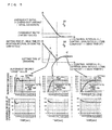
- Fig. 5 is a diagram illustrating the relationship of the overshoot ratio a/A and the setting time ST using, as parameters, the control interval Cl, the time constant ⁇ , the dead time DT, and the control gain ratio ⁇ .
- the ordinate is the overshoot ratio
- the graph 501 indicates that, for example, assuming that the control gain ratio ⁇ , the time constant ⁇ , and the dead time DT are fixed, as the control interval Cl increases, the overshoot ratio decreases.
- the ordinate corresponds to the setting time
- the graph 502 indicates that, for example, assuming that the control interval Cl, the time constant ⁇ , and the dead time DT are fixed, when the control gain ratio ⁇ is larger than ⁇ (B in Fig. 5 ) with the parameter ⁇ m with which the setting time is minimum (A in Fig. 5 ), the overshoot ratio increases and the hunting increases, so that the setting time is increased.
- the graph 502 indicates that, on the other hand, when the control gain ratio ⁇ is smaller than ⁇ (B in Fig. 5 ) with the parameter ⁇ m with which the setting time is minimum (C in Fig. 5 ), the overshoot ratio is small whereas the change amount is small and the setting time is long.
- the parameter ⁇ m with which the setting time is minimum is an eigenvalue (specifically, 2 to 3) determined by setting of the allowable setting range of the system as a control object.
- the time constant ⁇ as a control object will be described with reference to Fig. 6 .
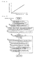
- the time constant ⁇ of the degree of superheat SH can lead a linear correlation expression with a value obtained by dividing the internal capacity Vcond [m 3 ] of a condenser with a large existing refrigerant amount by a product obtained by multiplying the displacement Vst [m 3 ] of the compressor 3 by the compressor frequency f [Hz] and then by the volumetric efficiency ⁇ v [-] of the compressor.
- the volumetric efficiency ⁇ v of the compressor may be a fixed value (for example, 0.9), and also, may be calculated as a function of the operating frequency f of the compressor and the compression ratio between a high pressure measured by the pressure sensor 52 and a low pressure measured by the pressure sensor 51.
- the eigenvalue of the parameter ⁇ m with which the setting time is minimum is about 2 to 3 and, when it is assumed that the dead time DT is substantially zero, the control gain ratio ⁇ is 1 or less, and therefore, the control interval Cl of the system of the control object may be set to three times the time constant ⁇ or less. That is, when the control gain ratio ⁇ is increased, the control interval Cl is large and the number of times of driving a drive unit that drives an electric expansion valve is reduced, so that abrasion of a slide unit of the electric expansion valve is reduced and reliability is increased.
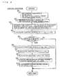
- Fig. 7 is a flow chart of control performed when the control interval Cl is fixed.
- the control interval Cl and the target degree of superheat SHm are set in advance (S1). Note that, because of energy-saving effectiveness in a refrigeration cycle, as the target degree of superheat SHm decreases, the energy-saving effect increases.
- the degree of superheat SH of the compressor 3 and the current opening degree LPnow of the expansion device 7 are measured (S2).
- the time constant ⁇ is estimated on the basis of information about the condenser internal capacity Vcond, the compressor frequency f of the compressor 3, the displacement Vst of the compressor 3, and the volumetric efficiency ⁇ v of the compressor 3 (S3).
- the condenser internal capacity is proportional to the horse power of the air-conditioner
- the condenser internal capacity can be estimated to some extent on the basis of the maximum operating capacity of the compressor and the like and, on the other hand, the displacement of the compressor can be estimated to some extent on the basis of the horse power of the air-conditioner.
- the control gain ratio ⁇ is calculated using the control interval Cl, the minimum setting time specific parameter ⁇ m (an eigenvalue), the time constant ⁇ , and the dead time DT (S4). In this case, since the dead time DT is substantially zero, the dead time DT may be set as a fixed value in advance.
- it is determined whether or not time corresponding to the control interval Cl or more has elapsed since the previous operation of the expansion device 7 (S5). If time corresponding to the control interval Cl or more has elapsed, in the control constant calculation means 21, the response gain K ⁇ ( Cpg / ⁇ he x LPnow) is calculated on the basis of each value obtained from the operating state of the refrigeration cycle (S6).
- Fig. 8 is a flow chart of control performed when the control gain ratio ⁇ is fixed.
- the control method is basically similar to the method illustrated in Fig. 7 , but this control method is different from that of Fig. 7 in that, in Step S4, an optimal control interval Cl is calculated each time so that the control interval is variable.
- Embodiment 1 a cooling operation has been described, but even in a heating operation, the expansion device 7 can be controlled in a similar manner in accordance with the above-described control method.
- load side heat exchanger internal capacity information is replaced with the condenser internal capacity Vcond, but the flow charts corresponding to Fig. 7 and Fig. 8 are the same as those of Fig. 7 and Fig. 8 .
- the state quantity of the refrigeration cycle which is a control amount, is the degree of superheat SH, but for the refrigerant temperature at the discharge side of the compressor 3 (the temperature detected by the thermal sensor 43) or the degree of supercooling SC at the outlet of the outdoor heat exchanger 9, a similar operation to the foregoing can be performed by changing a value which has been set in advance in the measurement control device 18, and such an operation is not out of the scope of the present invention.
- Embodiment 1 a case where a single indoor unit is provided at the load side has been described, but even in a multi-type air-conditioning apparatus including a plurality of indoor units, similar advantages may be achieved.
- Embodiment 1 a case where the compressor 3 is a capacity variable compressor has been described, but even in an air-conditioning apparatus including a constant-velocity compressor, similar advantages may be achieved.
- Reference Signs List a case where the compressor 3 is a capacity variable compressor has been described, but even in an air-conditioning apparatus including a constant-velocity compressor, similar advantages may be achieved.
Landscapes
- Engineering & Computer Science (AREA)
- Mechanical Engineering (AREA)
- General Engineering & Computer Science (AREA)
- Chemical & Material Sciences (AREA)
- Combustion & Propulsion (AREA)
- Physics & Mathematics (AREA)
- Thermal Sciences (AREA)
- Fuzzy Systems (AREA)
- Mathematical Physics (AREA)
- Signal Processing (AREA)
- Air Conditioning Control Device (AREA)
Abstract
Description
- The present invention relates to a refrigeration cycle, and more particularly, relates to a control device for an electric expansion valve. The control device is suitable for use in controlling the state quantity of the refrigeration cycle.
- Conventionally, as a method for controlling the flow rate of a refrigerant using an electric expansion valve so that the state quantity of a refrigeration cycle, such as temperature, pressure, or the like of the refrigerant is to be a predetermined value, a method has been proposed in which the control gain of PID control stored in a microcomputer in advance is calculated in accordance with indoor temperature, outdoor temperature, and rotation speed of a compressor, and the electric expansion valve is driven by PID control to thereby control the flow rate of the refrigerant (see, for example, Patent Literature 1).
- Another method has been proposed in which the control gain and control intervals of PID control stored in advance as a table in a microcomputer are determined in accordance with the number of interconnected indoor units which are in operation and a deviation from a control target value, and an electric expansion valve is driven by PID control to thereby control the flow rate of a refrigerant (see, for example, Patent Literature 2).
- In addition, there has been another method proposed in which the control gain and control intervals of PID control are determined in accordance with the opening degree of an electric expansion valve, the compressor operating capacity, and a deviation from a control target value, and the electric expansion valve is driven by PID control to thereby control the flow rate of a refrigerant (see, for example, Patent Literature 3).
-
- Patent Literature 1: Japanese Patent No.
2515716 Page 3,Fig. 6 ) - Patent Literature 2: Japanese Unexamined Patent Application Publication No.
3-28676 Page 5, Table 2) - Patent Literature 3: Japanese Unexamined Patent Application Publication No.
2001-012808 Page 7,Fig. 2 ) - However, the known air-conditioning apparatuses have the following problems: First, in the control described in
Patent Literature 1, the control gain of PID control is a system specific value of the air-conditioning apparatus, and therefore, when the type of a refrigerant and the internal capacity of a heat exchanger of the air-conditioning apparatus differ, the time constant and the dead time also differ. Accordingly, each time the specifications or model of the air-controlling apparatus changes, the optimal control gain and control intervals need to be obtained by performing a test and a simulation and stored in a microcomputer, and therefore, a problem arises in which a huge storage area is needed and a vast amount of time is spent in order to determine a constant. - In the control described in each of
Patent Literature 2 andPatent Literature 3, the gain and control intervals are determined in accordance with the number of indoor units in operation and a deviation from a control target value. However, the control constant is held in a table and thus is a certain value (a fixed value) even when an operation state, such as indoor and outdoor environmental conditions, the amount of a circulating refrigerant, or the like, has changed, and an influence caused when the operation state has changed, for example, such that the pressure becomes high or low in a refrigeration cycle is not taken into consideration. Thus, it is difficult to perform control in an optimal state in accordance with the environmental condition and operation state at all the time. Therefore, a system of the refrigeration cycle is not stabilized, hunting is caused, and the air-conditioning capacity is not stabilized. Under certain circumstances, a problem arises in which the overshoot amount is large to cause excessive rise of high-pressure side pressure or reduction of low-pressure side pressure and the operation has to be suspended for the purpose of protecting operation of air-conditioning equipment. - In view of the foregoing, the present invention has been devised, and therefore, it is an object of the present invention to provide an air-conditioning apparatus capable of being controlled optimally in which the control gain or control intervals of an electric expansion valve is optimized in accordance with the operation state of the air-conditioning apparatus and the system configuration thereof and overshoot is reduced in the shortest setting time at all the time such that the value of a control object is to be a control target value.
- In order to achieve the above-described object, the following has been devised according to the present invention.
- An air-conditioning apparatus according to the present invention is an air-conditioning apparatus in which at least one load side unit including a load side heat exchanger is connected to a heat source side unit including a compressor, a heat source side heat exchanger, and an expansion device, and a refrigerant is circulated between the units to form a refrigeration cycle, the apparatus including a measurement unit that measures an operating state quantity of the refrigeration cycle of the air-conditioning apparatus, and a control unit including time constant calculation means that estimates a response time constant at a time when an opening degree of the expansion device is changed on the basis of specifications of a compressor that forms the refrigeration cycle, specifications of a condenser heat exchanger, and the operating state quantity of the refrigeration cycle, control constant calculation means that calculates at least one of a control gain of the opening degree of the expansion device and a control interval on the basis of a calculation result of the time constant calculation means and a measurement result of the measurement unit, control constant change means that changes the control gain or the control interval on the basis of the calculation result of the control constant calculation means, and expansion device control means that changes the opening degree of the expansion device on the basis of the control constant.
- An expansion device is controlled at optimal time intervals or with an optimal control gain in accordance with the specification of a compressor of an air-conditioning apparatus, the specification of a load side heat exchanger, and the operating state quantity of a refrigeration cycle, and thus, a stable state of the refrigeration cycle can be obtained promptly without causing overshoot, so that further increased energy-saving effectiveness, a higher degree of comfort, and improvement of production quality can be achieved.
- In addition, since the refrigeration cycle is stabilized in a short time, the amount of change of a drive unit that drives an electric expansion valve of an expansion device is reduced, so that the abrasion of a slide unit of the electric expansion valve is reduced and reliability is increased.
-
- [
Fig. 1] Fig. 1 is a system chart of an air-conditioning apparatus according toEmbodiment 1 of the present invention. - [
Fig. 2] Fig. 2 is a p-h diagram of the air-conditioning apparatus according toEmbodiment 1 of the present invention. - [
Fig. 3] Fig. 3 is a conceptual diagram illustrating change that occurs when a control object is controlled to be a control target value in a dead time + first order lag system. - [
Fig. 4] Fig. 4 is a graph illustrating the relationship among control interval, time constant, dead time, response gain, and control gain obtained when maximum overshoot ratio is fixed. - [
Fig. 5] Fig. 5 is a diagram illustrating the relationship of overshoot ratio and setting time with control interval, time constant, dead time, and control gain ratio. - [
Fig. 6] Fig. 6 is a graph illustrating the relationship among condenser internal capacity, compressor frequency, volumetric efficiency, and response time constant of the suction degree of superheat. - [
Fig. 7] Fig. 7 is a flow chart of control performed on an expansion device when control interval is fixed in the air-conditioning apparatus according toEmbodiment 1 of the present invention. - [
Fig. 8] Fig. 8 is a flow chart of control performed on the expansion device when control gain ratio is fixed in the air-conditioning apparatus according toEmbodiment 1 of the present invention. -
Embodiment 1 of the present invention will be described below in detail with reference to the accompanying drawings. -
Fig. 1 is a circuit diagram of a refrigerant circuit of an air-conditioning apparatus 100 according toEmbodiment 1 of the present invention. The air-conditioning apparatus 100 includes anoutdoor unit 1 and anindoor unit 2. Acompressor 3, a four-way valve 4 serving as a flow switching valve that performs operation switching between heating and cooling, anexpansion device 7, and an outdoor heat exchanger (a heat source side heat exchanger) 9 are installed in theoutdoor unit 1. An indoor heat exchanger (a load side heat exchanger) 6 is installed in theindoor unit 2. - The
compressor 3 is a type of compressor in which the rotation speed is controlled by an inverter and the capacity is controlled. - The
expansion device 7 is an electric expansion valve the opening degree of which is variably controlled. Theoutdoor heat exchanger 9 exchanges heat with outside air ventilated by a fan, or the like. Agas tube 5 and a liquid tube 8 are connection tubes that connect theoutdoor unit 1 and theindoor unit 2. - Refrigerants that can be used for a refrigeration cycle of the air-
conditioning apparatus 100 include a zeotropic refrigerant mixture, a near-azeotropic refrigerant mixture, a single refrigerant, and the like. Zeotropic refrigerant mixtures include R407C (R32/R125/R134a), which is a hydrofluorocarbon (HFC) refrigerant, and the like. Such a zeotropic refrigerant mixture is a mixture of refrigerants having boiling points different from each other, and thus, has a characteristic in which the composition ratio differs between a liquid phase and a gas phase. Near-azeotropic refrigerant mixtures include R410A (R32/R125), R404A (R125/R143a/R134a), each of which is an HFC refrigerant, and the like. Such a near-azeotropic refrigerant mixture has, in addition to a similar characteristic to that of the zeotropic refrigerant mixture, a characteristic in which it has a working pressure that is about 1.6 times the working pressure of R22. - Single refrigerants include R22, which is a hydrochlorofluorocarbon (HCFC) refrigerant, R134a, which is a HFC refrigerant, R1234yf and R1234ze, which are hydrofluoroolefin (HFO) refrigerants, and the like. Such a single refrigerant is not a mixture, and therefore, has a characteristic that it can be easily handled. In addition to the above-described refrigerants, carbon dioxide, propane, isobutene, ammonia, and the like, may be used. Note that R22, R32, R125, R134a, and R143a represent chlorodifluoromethane, difluoromethane, pentafluoroethane, 1,1,1,2-tetrafluoroethane, and 1,1,1-trifluoroethane, respectively. Accordingly, a refrigerant suitable for use and the purpose of the air-
conditioning apparatus 100 may be used. - A
measurement control device 18 and a plurality of thermal sensors are installed in theoutdoor unit 1. Athermal sensor 43, athermal sensor 44, andthermal sensor 45 measure refrigerant temperatures in an installation location at a discharge side of thecompressor 3, an installation location at a suction side of thecompressor 3, and an installation location between theoutdoor heat exchanger 9 and theexpansion device 7, respectively. Furthermore,pressure sensors outdoor unit 1 and thepressure sensor 51 and thepressure sensor 52 measure the pressure of a refrigerant to be sucked into thecompressor 3 and the pressure of a refrigerant discharged from thecompressor 3, respectively. -
Thermal sensors indoor unit 2. Thethermal sensor 42 is provided between anindoor heat exchanger 6 and theexpansion device 7 and measures the temperature of a refrigerant flowing therein. Thethermal sensor 41 measures the temperature of air sucked into theindoor heat exchanger 6. Note that, when a heat medium that is to be a load is some other medium, such as water, thethermal sensor 41 measures the inflow temperature of the medium. - The
measurement control device 18 of theoutdoor unit 1 includes ameasurement unit 16 that measures operating information instructed by each sensor and a user of the air-conditioning apparatus and acontrol unit 17 that controls, on the basis of the measured information, a method for operating thecompressor 3, flow switching of the four-way valve 4, the fan ventilation amount of theoutdoor heat exchanger 9, the opening degree of theexpansion device 7, and the like. Note thatFig. 1 illustrates only a case where an operation object is an expansion device and does not illustrate other operation objects. Also, themeasurement unit 16 holds in advance information about the respective internal capacities of theindoor heat exchanger 6 and theoutdoor heat exchanger 9 and the (liquid) displacement amount of the compressor. - Next, the cooling operation of the air-
conditioning apparatus 100 will be described with reference toFig. 1 . When the cooling operation is performed, the flow switched in the four-way valve 4 is set to extend in the direction in which the solid line extends inFig. 1 . A high-temperature, high-pressure gas refrigerant discharged from thecompressor 3 is condensed and liquefied, while passing through the four-way valve 4 and transferring heat in theoutdoor heat exchanger 9 that is to serve as a condenser, to be a high-pressure liquid refrigerant. The high-pressure refrigerant that has come out of theoutdoor heat exchanger 9 flows, after being decompressed by theexpansion device 7, into theindoor unit 2 via the liquid tube 8, and then, into theindoor heat exchanger 6 that is an evaporator, removes heat there, and is thus evaporated and gasified. Cooling is performed by removing heat from a load side medium, such as air, water at the indoor unit side, and the like. Thereafter, the evaporated and gasified refrigerant flows into theoutdoor unit 1 via thegas tube 5. Then, the refrigerant is sucked by thecompressor 3 via the four-way valve 4. - In the air-
conditioning apparatus 100, the cooling capacity that the air-conditioning apparatus 1 is required to have changes in accordance with the heat load at the indoor side, and therefore, the air-conditioning apparatus 100 needs to cope with the change of the cooling capacity required when a cooling operation is performed. Thus, in the air-conditioning apparatus 100, control is performed to change the operating capacity of thecompressor 3 such that the temperature detected by thethermal sensor 41 at the indoor side (the load side) becomes close to the indoor temperature instructed by the user of the air-conditioning apparatus. In this case, control of the operating capacity of thecompressor 3 is performed by changing the operating frequency f of thecompressor 3. - Next, an example method for controlling the
expansion device 7 according to a feature of the present invention will be described with reference toFig. 2 . The air-conditioning apparatus 100 controls the opening degree of theexpansion device 7 such that the degree of superheat SH of the refrigerant to be sucked into thecompressor 3 is a target degree of superheat SHm. In this case, the degree of superheat SH of a refrigerant in suction of thecompressor 3 is calculated from a suction pressure Ps detected by thepressure sensor 51 and a refrigerant temperature Ts detected by thethermal sensor 44 of a suction unit of thecompressor 3. More specifically, first, the suction pressure Ps detected by thepressure sensor 51 is converted into the saturation temperature of the refrigerant to obtain an evaporating temperature Te. Then, the evaporating temperature Te is deducted from the refrigerant temperature Ts detected by thethermal sensor 44 to obtain the degree of superheat SH. - Then, assume that, when the current suction state of the compressor is in the state of (d) of
Fig. 2 , the degree of superheat at that time is denoted by SH, theexpansion device 7 is opened by an operation performed once, and theexpansion device 7 is successfully controlled such that the state of a target degree of superheat SHm of (d2) ofFig. 2 is achieved. In this case, it is assumed that the high-pressure side pressure or low-pressure side pressure in the refrigeration cycle does not change and the cooling capacity in theindoor heat exchanger 6 is the same. When the drive opening degree of an electric pulse motor that controls the area of the opening port of theexpansion device 7 is LP [pulse], the amount of a circulating refrigerant that passes through theexpansion device 7 is proportional to LP. Assume that a current opening degree is LP and an opening degree change amount required in controlling the degree of superheat to the target degree of superheat SHm by an operation performed once is ΔLP. In addition, when a deviation of the current degree of superheat SH, which is a control object, from the target degree of superheat SHm is expressed as ΔSHm = SH - SHm, the specific enthalpy difference ΔHs [kJ/kg] between (d) and (d2) can be expressed by the following expression. - (Math. 1)

- In this expression, Cpg is gas specific heat at constant pressure [kJ/kgK]. This value is specifically calculated from the value of the pressure of the
pressure sensor 51 and the value from thethermal sensor 44 of the suction unit of thecompressor 3. Also, on the basis of the assumption that cooling capacity is constant before and after the operation of theexpansion device 7 and the assumption that the amount of a circulating refrigerant is proportional to LP, the following expression holds. - (Math. 2)

- In this expression, ΔHe denotes the enthalpy change of a refrigerant in an evaporator (the
indoor heat exchanger 6 in a cooling operation) when the degree of superheat of the refrigerant sucked into thecompressor 3 is the target degree of superheat SHm. Specifically, the enthalpy difference ΔHe can be calculated by deducting an enthalpy Hei calculated from the values of thepressure sensor 52 and thethermal sensor 45 at an inlet of theexpansion device 7 from an enthalpy Heo calculated from the temperature obtained by adding the target degree of superheat SHm to the saturated gas temperature obtained from the pressure of thepressure sensor 51. WhenExpression 1 andExpression 2 are put together by substitutingExpression 1 intoExpression 2, the following expression holds. - (Math. 3)

-
Expression 3 represents the relationship between the deviation ΔSHm, which is a control object, and the operation amount ΔLP, and thus, Cpg / ΔHe × LP on the right side represents a response gain (which will be hereinafter referred to as K∞) that is the control object used for achieving the control target value by an operation performed once. - Since the air-
conditioning apparatus 100 is to be controlled at certain control intervals Cl [sec], when the control is performed with the response gain K∞, an operation is performed a plurality of times whereas the operation amount may be sufficient by a control operation performed once, and therefore, under certain circumstances, the air-conditioning apparatus 100 is excessively operated, thus causing hunting. Therefore, as an actual control gain (which will be hereinafter referred to as K), a value smaller than the response gain K∞ has to be selected. In order to obtain the optimal control gain K that is to be selected, the change of the degree of superheat SH is set to be a "dead time + first order lag" system, and a control response characteristic corresponding to this system is quantified. -
Fig. 3 illustrates the response characteristic of a control object of the "dead time + first order lag" system. When the control gain is set to be a certain value in a control system, an operation amount is changed in a stepwise manner, and the response characteristic of the control amount is plotted, a graph ofFig. 3 is obtained. The maximum value with which the control amount exceeds the control target value is, in general, called overshoot amount or overshoot. The time which it takes for the control amount to be in a setting range, which is a desired allowable range, with the control target value centered is called setting time ST. It is assumed that the deviation of the current control amount from the control target value is A and the overshoot amount is a, a/A is defined as the overshoot ratio. The dead time DT is, in other words, a time period from the time when an opening degree change order is issued to theexpansion device 7 to the time when a change appears in the control target object. - In an air-conditioning apparatus, in view of energy-saving effectiveness and the characteristics of load following, a fast response to a target value is desired, but when the setting time is reduced, the overshoot ratio increases. Depending on conditions, there are cases where the overshoot ratio is not allowable. For example, a high-pressure refrigerant, such as an R32 refrigerant, has a high specific heat ratio because of the characteristics of the refrigerant, and the discharge temperature of the refrigerant from the compressor tends to rise. When the discharge temperature is a control object, with a large overshoot ratio, the efficiency of the compression is reduced due to demagnetization of a magnet used in a motor of the
compressor 3 and damage is caused by burning of a refrigerating machine oil, as a result of a rise in discharge temperature, thus, the overshoot ratio has to be reduced. -
Fig. 4 is a graph illustrating a state in which the overshoot ratio is the maximum value in a desired setting range. That is,Fig. 4 illustrates the relationship of the control gain ratio β (= K/K∞), defined as the ratio of the control gain K to the response gain K∞, in relation to the control interval Cl, the time constant τ, and the dead time DT. The abscissa and the ordinate are both dimensionless, and therefore, in the "dead time + first order lag" system, this relationship is kept at all times. For example, it is indicated that, when the control interval CI and the certain dead time DT are constant, as the time constant τ increases, the response speed of the system decreases, and therefore, the control gain ratio β has to be reduced. It is also indicated that, when the time constant τ and the certain dead time DT are constant, as the control interval Cl decreases, the control gain ratio β has to be reduced. - Thus, for example, when the control interval Cl is fixed, the control gain ratio β is calculated in accordance with the time constant τ and the dead time DT of the system of an object to determine the control gain K, thus realizing an optimal operation in which the setting time is minimum under the condition where the overshoot ratio is a desired ratio or less at all times.
-
Fig. 5 is a diagram illustrating the relationship of the overshoot ratio a/A and the setting time ST using, as parameters, the control interval Cl, the time constant τ, the dead time DT, and the control gain ratio β. Ingraphs Fig. 5 , the abscissa is a dimensionless parameter or index under the definition of ξ = (the control interval CI / the control gain ratio β) / (the time constant τ / the dead time DT). - In the
graph 501 ofFig. 5 , the ordinate is the overshoot ratio, and thegraph 501 indicates that, for example, assuming that the control gain ratio β, the time constant τ, and the dead time DT are fixed, as the control interval Cl increases, the overshoot ratio decreases. - In the
graph 502 ofFig. 5 , the ordinate corresponds to the setting time, and thegraph 502 indicates that, for example, assuming that the control interval Cl, the time constant τ, and the dead time DT are fixed, when the control gain ratio β is larger than β (B inFig. 5 ) with the parameter ξm with which the setting time is minimum (A inFig. 5 ), the overshoot ratio increases and the hunting increases, so that the setting time is increased. Thegraph 502 indicates that, on the other hand, when the control gain ratio β is smaller than β (B inFig. 5 ) with the parameter ξm with which the setting time is minimum (C inFig. 5 ), the overshoot ratio is small whereas the change amount is small and the setting time is long. - The parameter ξm with which the setting time is minimum is an eigenvalue (specifically, 2 to 3) determined by setting of the allowable setting range of the system as a control object. On the other hand, the time constant τ and the dead time DT of the system as a control object are determined in accordance with an operation state. Therefore, at least one of the control interval Cl and the control gain ratio β is changed such that the relationship of the parameter ξm, with which the setting time is minimum, = (the control interval Cl / the control gain ratio β) / (the time constant τ + the dead time DT), and thus, an optimal operation in which the setting time is minimum under the condition where the overshoot ratio is a desired ratio or less at all times.
- The time constant τ as a control object will be described with reference to
Fig. 6 . Assuming a case of the first-order lag system, in accordance with the law of mass conservation, the time constant τ of the degree of superheat SH can lead a linear correlation expression with a value obtained by dividing the internal capacity Vcond [m3] of a condenser with a large existing refrigerant amount by a product obtained by multiplying the displacement Vst [m3] of thecompressor 3 by the compressor frequency f [Hz] and then by the volumetric efficiency ηv [-] of the compressor. Therefore, holding in advance the internal capacity of theindoor heat exchanger 6, the internal capacity of theoutdoor heat exchanger 9, and the displacement amount of thecompressor 3 as information allows estimation of the time constant τ of the degree of superheat SH on the basis of the compressor frequency f specified by thecontrol unit 17. The volumetric efficiency ηv of the compressor may be a fixed value (for example, 0.9), and also, may be calculated as a function of the operating frequency f of the compressor and the compression ratio between a high pressure measured by thepressure sensor 52 and a low pressure measured by thepressure sensor 51. - The eigenvalue of the parameter ξm with which the setting time is minimum is about 2 to 3 and, when it is assumed that the dead time DT is substantially zero, the control gain ratio β is 1 or less, and therefore, the control interval Cl of the system of the control object may be set to three times the time constant τ or less. That is, when the control gain ratio β is increased, the control interval Cl is large and the number of times of driving a drive unit that drives an electric expansion valve is reduced, so that abrasion of a slide unit of the electric expansion valve is reduced and reliability is increased.
- Next, control of the degree of superheat SH of the
expansion device 7 performed in consideration of the above-described control responsiveness will be described with reference to the flow charts ofFig. 7 andFig. 8 . -
Fig. 7 is a flow chart of control performed when the control interval Cl is fixed. First, in themeasurement control device 18, the control interval Cl and the target degree of superheat SHm are set in advance (S1). Note that, because of energy-saving effectiveness in a refrigeration cycle, as the target degree of superheat SHm decreases, the energy-saving effect increases. Next, in themeasurement unit 16, the degree of superheat SH of thecompressor 3 and the current opening degree LPnow of theexpansion device 7 are measured (S2). Next, in a time constant calculation means 20, the time constant τ is estimated on the basis of information about the condenser internal capacity Vcond, the compressor frequency f of thecompressor 3, the displacement Vst of thecompressor 3, and the volumetric efficiency ηv of the compressor 3 (S3). Note that, because the condenser internal capacity is proportional to the horse power of the air-conditioner, the condenser internal capacity can be estimated to some extent on the basis of the maximum operating capacity of the compressor and the like and, on the other hand, the displacement of the compressor can be estimated to some extent on the basis of the horse power of the air-conditioner. - Next, in a control constant calculation means 21, the control gain ratio β is calculated using the control interval Cl, the minimum setting time specific parameter ξm (an eigenvalue), the time constant τ, and the dead time DT (S4). In this case, since the dead time DT is substantially zero, the dead time DT may be set as a fixed value in advance. Next, it is determined whether or not time corresponding to the control interval Cl or more has elapsed since the previous operation of the expansion device 7 (S5). If time corresponding to the control interval Cl or more has elapsed, in the control constant calculation means 21, the response gain K∞ (= Cpg / Δhe x LPnow) is calculated on the basis of each value obtained from the operating state of the refrigeration cycle (S6). Next, in the control constant calculation means 21, the control gain K (= β x K∞) is calculated (S7). Next, a deviation ΔSHm (= SH - SHm) of the degree of superheat SH from the target degree of superheat SHm is calculated (S8). Next, in a control constant change means 22, the control gain K is changed and the changed control gain K and the deviation ΔSHm are multiplied to calculate the opening degree change amount ΔLP = (K × ΔSHm) of the expansion device 7 (S9). Next, in an expansion device control means 23, the opening degree change amount ΔLP is added to the current opening degree LPnow of the
expansion device 7 to calculate the opening degree LP = LPnow + ΔLP, and the opening degree of theexpansion device 7 is set to be the calculated expansion opening degree LP (S10). -
Fig. 8 is a flow chart of control performed when the control gain ratio β is fixed. The control method is basically similar to the method illustrated inFig. 7 , but this control method is different from that ofFig. 7 in that, in Step S4, an optimal control interval Cl is calculated each time so that the control interval is variable. - When the air-conditioning apparatus is controlled in the above-described manner, an optimal operation in which the setting time is minimum under the condition where the overshoot ratio is within an allowable range at all times can be achieved in accordance with the system configuration and operating state of the air-conditioning apparatus.
- Note that, in
Embodiment 1, a cooling operation has been described, but even in a heating operation, theexpansion device 7 can be controlled in a similar manner in accordance with the above-described control method. In a heating operation, load side heat exchanger internal capacity information is replaced with the condenser internal capacity Vcond, but the flow charts corresponding toFig. 7 andFig. 8 are the same as those ofFig. 7 andFig. 8 . - The state quantity of the refrigeration cycle, which is a control amount, is the degree of superheat SH, but for the refrigerant temperature at the discharge side of the compressor 3 (the temperature detected by the thermal sensor 43) or the degree of supercooling SC at the outlet of the
outdoor heat exchanger 9, a similar operation to the foregoing can be performed by changing a value which has been set in advance in themeasurement control device 18, and such an operation is not out of the scope of the present invention. - In
Embodiment 1, a case where a single indoor unit is provided at the load side has been described, but even in a multi-type air-conditioning apparatus including a plurality of indoor units, similar advantages may be achieved. - Furthermore, in
Embodiment 1, a case where thecompressor 3 is a capacity variable compressor has been described, but even in an air-conditioning apparatus including a constant-velocity compressor, similar advantages may be achieved. Reference Signs List - 1 Outdoor unit; 2 Indoor unit; 3 Compressor; 4 Four-way valve, 5 Gas tube; 6 Indoor heat exchanger (load side heat exchanger); 7 Expansion device, 8 Liquid tube; 9 Outdoor heat exchanger (heat source side heat exchanger); 16 Measurement unit; 17 Control unit; 18 Measurement control device; 20 Time constant calculation means; 21 Control constant calculation means; 22 Control constant change means; 23 Expansion device control means; 41 Thermal sensor; 42 Thermal sensor; 43 Thermal sensor; 44 Thermal sensor; 45 Thermal sensor; 51 Pressure sensor; 52 Pressure sensor; and 100 Air-conditioning apparatus
Claims (7)
- An air-conditioning apparatus in which at least one load side unit including a load side heat exchanger is connected to a heat source side unit including a compressor, a heat source side heat exchanger, and an expansion device, and a refrigerant is circulated between the units to form a refrigeration cycle, the apparatus comprising:a measurement unit that measures an operating state quantity of the refrigeration cycle of the air-conditioning apparatus; anda control unit including time constant calculation means that estimates a response time constant at a time when an opening degree of the expansion device is changed on the basis of specifications of the compressor that forms the refrigeration cycle, specifications of a condenser heat exchanger, and the operating state quantity of the refrigeration cycle, control constant calculation means that calculates at least either of a control gain of the opening degree of the expansion device and a control interval on the basis of a calculation result of the time constant calculation means and a measurement result of the measurement unit, control constant change means that changes the control gain or the control interval on the basis of the calculation result of the control constant calculation means, and expansion device control means that changes the opening degree of the expansion device on the basis of the control constant.
- The air-conditioning apparatus of claim 1,
wherein the control interval is set to be three times the response time constant or less calculated in the time constant calculation means. - The air-conditioning apparatus of claim 1 or 2,
wherein, when the response time constant is estimated in the time constant calculation means, information regarding an operating frequency of the compressor is used. - The air-conditioning apparatus of claim 3,
wherein, when the response time constant is estimated in the time constant calculation means, information regarding at least any of an internal capacity of the heat source side heat exchanger, an internal capacity of the load side heat exchanger, and a displacement of the compressor is used. - The air-conditioning apparatus of claim 3 or 4,
wherein, when the response time constant is estimated in the time constant calculation means, a volumetric efficiency of the compressor is used and the volumetric efficiency is estimated on the basis of a discharge pressure, a suction pressure, and an operating frequency of the compressor. - The air-conditioning apparatus of any one of claims 1-5,
wherein the response time constant estimated in the time constant calculation means satisfies a relationship that an eigenvalue with which a setting time is minimum = (control interval / control gain ratio) / (response time constant + dead time),
the setting time is a time for a control target object to be in a predetermined range from a control target value,
the gain ratio is a value obtained by dividing the control gain by a response gain of the control target object in order to cause the control gain to be a control target value by an operation performed once, and
a dead time is a time from a time when an opening degree change order is issued to the expansion device to a time when a change appears in the control target object. - The air-conditioning apparatus of claim 6,
wherein the response time constant is estimated assuming that the dead time is zero.
Applications Claiming Priority (1)
| Application Number | Priority Date | Filing Date | Title |
|---|---|---|---|
| PCT/JP2012/002857 WO2013160949A1 (en) | 2012-04-26 | 2012-04-26 | Air conditioner |
Publications (3)
| Publication Number | Publication Date |
|---|---|
| EP2863138A1 true EP2863138A1 (en) | 2015-04-22 |
| EP2863138A4 EP2863138A4 (en) | 2016-03-30 |
| EP2863138B1 EP2863138B1 (en) | 2020-04-22 |
Family
ID=49482326
Family Applications (1)
| Application Number | Title | Priority Date | Filing Date |
|---|---|---|---|
| EP12875142.7A Active EP2863138B1 (en) | 2012-04-26 | 2012-04-26 | Air conditioner |
Country Status (6)
| Country | Link |
|---|---|
| US (1) | US9976766B2 (en) |
| EP (1) | EP2863138B1 (en) |
| JP (1) | JP5932979B2 (en) |
| CN (1) | CN104254742B (en) |
| AU (1) | AU2012378582B2 (en) |
| WO (1) | WO2013160949A1 (en) |
Families Citing this family (10)
| Publication number | Priority date | Publication date | Assignee | Title |
|---|---|---|---|---|
| WO2014160740A1 (en) * | 2013-03-26 | 2014-10-02 | Aaim Controls, Inc. | Refrigeration circuit control system |
| EP3006847B1 (en) * | 2013-05-27 | 2021-03-31 | Mitsubishi Electric Corporation | Air-conditioning device |
| WO2015136651A1 (en) * | 2014-03-12 | 2015-09-17 | 三菱電機株式会社 | Air-conditioning device |
| US11162705B2 (en) * | 2019-08-29 | 2021-11-02 | Hitachi-Johnson Controls Air Conditioning, Inc | Refrigeration cycle control |
| JP7216309B2 (en) * | 2021-05-07 | 2023-02-01 | ダイキン工業株式会社 | air conditioner |
| US20240183566A1 (en) * | 2021-05-24 | 2024-06-06 | Mitsubishi Electric Corporation | Air conditioner |
| CN113959080B (en) * | 2021-09-30 | 2023-04-25 | 青岛海尔空调电子有限公司 | Control method for electronic expansion valve of air conditioning unit |
| US12013161B2 (en) * | 2021-12-01 | 2024-06-18 | Haier Us Appliance Solutions, Inc. | Method of operating an electronic expansion valve in an air conditioner unit |
| WO2025173128A1 (en) * | 2024-02-14 | 2025-08-21 | 三菱電機株式会社 | Prediction apparatus, prediction method, and prediction program |
| WO2026033875A1 (en) * | 2024-08-09 | 2026-02-12 | 三菱電機株式会社 | Refrigeration cycle device and method for controlling same |
Family Cites Families (24)
| Publication number | Priority date | Publication date | Assignee | Title |
|---|---|---|---|---|
| JP2515716B2 (en) | 1984-02-27 | 1996-07-10 | 株式会社日立製作所 | Air conditioner |
| JPS61237978A (en) * | 1985-04-13 | 1986-10-23 | ダイキン工業株式会社 | Multi-type refrigeration equipment |
| US4744511A (en) * | 1985-11-27 | 1988-05-17 | Nippondenso Co., Ltd. | Air conditioner for automobiles |
| JPS638802A (en) * | 1986-06-27 | 1988-01-14 | Matsushita Electric Ind Co Ltd | Automatic adjustment method for control constants of PID controller |
| US4893480A (en) * | 1987-03-13 | 1990-01-16 | Nippondenso Co., Ltd. | Refrigeration cycle control apparatus |
| JPH0762576B2 (en) | 1989-06-26 | 1995-07-05 | ダイキン工業株式会社 | Refrigerant recovery device |
| JPH0380261U (en) * | 1989-12-04 | 1991-08-16 | ||
| US5222371A (en) * | 1989-12-28 | 1993-06-29 | Matsushita Electric Industrial Co., Ltd. | Air conditioner of multichamber type |
| US5436852A (en) * | 1990-09-21 | 1995-07-25 | Yamatake-Honeywell Co., Ltd. | Method and apparatus for calculating predicted mean thermal sensitivity |
| US5687077A (en) * | 1991-07-31 | 1997-11-11 | Universal Dynamics Limited | Method and apparatus for adaptive control |
| US5335164A (en) * | 1991-07-31 | 1994-08-02 | Universal Dynamics Limited | Method and apparatus for adaptive control |
| CN1098186A (en) * | 1993-03-29 | 1995-02-01 | 三洋电机株式会社 | The control device of air conditioner |
| US5867998A (en) * | 1997-02-10 | 1999-02-09 | Eil Instruments Inc. | Controlling refrigeration |
| JP2001012808A (en) * | 1999-06-29 | 2001-01-19 | Matsushita Electric Ind Co Ltd | Method and apparatus for controlling expansion valve of air conditioner |
| JP2003129956A (en) * | 2001-10-22 | 2003-05-08 | Toyota Industries Corp | Variable displacement compressor, air conditioner provided with the same, and capacity control method in the same |
| JP4043244B2 (en) * | 2002-01-29 | 2008-02-06 | 三菱重工業株式会社 | Air conditioner |
| JP2007040567A (en) * | 2005-08-01 | 2007-02-15 | Daikin Ind Ltd | Refrigerator |
| JP4596426B2 (en) * | 2005-09-21 | 2010-12-08 | 日立アプライアンス株式会社 | Heat source equipment |
| JP2007255845A (en) | 2006-03-24 | 2007-10-04 | Sanyo Electric Co Ltd | Refrigerating cycle device |
| US7653445B2 (en) * | 2007-04-13 | 2010-01-26 | Controlsoft, Inc. | Apparatus and method for model-based control |
| JP2009146241A (en) * | 2007-12-17 | 2009-07-02 | Fuji Koki Corp | Valve control device and valve control method |
| JP2009229012A (en) * | 2008-03-24 | 2009-10-08 | Daikin Ind Ltd | Refrigerating device |
| CN103502030B (en) * | 2011-02-10 | 2016-06-29 | 三电有限公司 | Air Conditioning Devices for Vehicles |
| CN102401524A (en) * | 2011-11-29 | 2012-04-04 | 宁波奥克斯电气有限公司 | Control method of electronic expansion valve in cooling operation of frequency conversion air conditioner |
-
2012
- 2012-04-26 CN CN201280072639.XA patent/CN104254742B/en active Active
- 2012-04-26 EP EP12875142.7A patent/EP2863138B1/en active Active
- 2012-04-26 WO PCT/JP2012/002857 patent/WO2013160949A1/en not_active Ceased
- 2012-04-26 US US14/391,761 patent/US9976766B2/en active Active
- 2012-04-26 AU AU2012378582A patent/AU2012378582B2/en not_active Ceased
- 2012-04-26 JP JP2014512018A patent/JP5932979B2/en active Active
Also Published As
| Publication number | Publication date |
|---|---|
| JPWO2013160949A1 (en) | 2015-12-21 |
| CN104254742B (en) | 2017-03-08 |
| US20150052922A1 (en) | 2015-02-26 |
| AU2012378582B2 (en) | 2015-07-30 |
| EP2863138A4 (en) | 2016-03-30 |
| JP5932979B2 (en) | 2016-06-08 |
| AU2012378582A1 (en) | 2014-12-18 |
| US9976766B2 (en) | 2018-05-22 |
| EP2863138B1 (en) | 2020-04-22 |
| CN104254742A (en) | 2014-12-31 |
| WO2013160949A1 (en) | 2013-10-31 |
Similar Documents
| Publication | Publication Date | Title |
|---|---|---|
| EP2863138B1 (en) | Air conditioner | |
| EP2620718B1 (en) | Device and method for air-cooling and hot-water supply | |
| EP3026371B1 (en) | Refrigeration cycle apparatus | |
| CN102077042B (en) | Method for judging amount of refrigerant of air conditioner and air conditioner | |
| Cho et al. | Effects of refrigerant charge amount on the performance of a transcritical CO2 heat pump | |
| EP2653805B1 (en) | Combined air-conditioning and hot water supply system | |
| Cho et al. | Cooling performance of a variable speed CO2 cycle with an electronic expansion valve and internal heat exchanger | |
| EP2878902A1 (en) | Air-conditioning device | |
| JP5430602B2 (en) | Air conditioner | |
| EP3999783B1 (en) | Air conditioner and control method thereof | |
| EP2808622A1 (en) | Air-conditioning device | |
| WO2016174767A1 (en) | Refrigeration cycle device and system for detecting annormalities in refrigeration cycle device | |
| Han et al. | Refrigerant migration during startup of a split air conditioner in heating mode | |
| JP6289734B2 (en) | Air conditioning and hot water supply complex system | |
| WO2019023267A1 (en) | Refrigerant composition measurement system | |
| EP2808625A1 (en) | Coolant replenishment method for air-conditioning unit, and air-conditioning unit | |
| Ataş et al. | Development and analysis of a multi-evaporator cooling system with electronic expansion valves | |
| CN107076476A (en) | Variable refrigerant HVAC system with independent defrosting | |
| US20230080007A1 (en) | Free cooling system for hvac system | |
| US11506435B2 (en) | Water regulator | |
| WO2017109905A1 (en) | Air-conditioning/hot-water supplying combined system | |
| WO2015136651A1 (en) | Air-conditioning device | |
| JP6537629B2 (en) | Air conditioner | |
| PADILLA | Exergy analysis of the performance of a variable refrigerant flow (VRF) air conditioning system | |
| Kang et al. | Effects of flash gas generation at the expansion device inlet on the dynamic characteristics of a refrigeration system |
Legal Events
| Date | Code | Title | Description |
|---|---|---|---|
| PUAI | Public reference made under article 153(3) epc to a published international application that has entered the european phase |
Free format text: ORIGINAL CODE: 0009012 |
|
| 17P | Request for examination filed |
Effective date: 20141121 |
|
| AK | Designated contracting states |
Kind code of ref document: A1 Designated state(s): AL AT BE BG CH CY CZ DE DK EE ES FI FR GB GR HR HU IE IS IT LI LT LU LV MC MK MT NL NO PL PT RO RS SE SI SK SM TR |
|
| AX | Request for extension of the european patent |
Extension state: BA ME |
|
| DAX | Request for extension of the european patent (deleted) | ||
| RA4 | Supplementary search report drawn up and despatched (corrected) |
Effective date: 20160226 |
|
| RIC1 | Information provided on ipc code assigned before grant |
Ipc: F25B 13/00 20060101ALI20160222BHEP Ipc: F25B 49/02 20060101ALI20160222BHEP Ipc: F24F 11/02 20060101AFI20160222BHEP Ipc: F25B 1/00 20060101ALI20160222BHEP Ipc: F24F 11/00 20060101ALI20160222BHEP |
|
| STAA | Information on the status of an ep patent application or granted ep patent |
Free format text: STATUS: EXAMINATION IS IN PROGRESS |
|
| 17Q | First examination report despatched |
Effective date: 20190326 |
|
| REG | Reference to a national code |
Ref country code: DE Ref legal event code: R079 Ref document number: 602012069570 Country of ref document: DE Free format text: PREVIOUS MAIN CLASS: F24F0011020000 Ipc: F24F0011300000 |
|
| RIC1 | Information provided on ipc code assigned before grant |
Ipc: F25B 1/00 20060101ALI20190925BHEP Ipc: F24F 11/00 20180101ALI20190925BHEP Ipc: F25B 13/00 20060101ALI20190925BHEP Ipc: F24F 11/30 20180101AFI20190925BHEP Ipc: F25B 49/02 20060101ALI20190925BHEP |
|
| GRAP | Despatch of communication of intention to grant a patent |
Free format text: ORIGINAL CODE: EPIDOSNIGR1 |
|
| STAA | Information on the status of an ep patent application or granted ep patent |
Free format text: STATUS: GRANT OF PATENT IS INTENDED |
|
| INTG | Intention to grant announced |
Effective date: 20191120 |
|
| GRAS | Grant fee paid |
Free format text: ORIGINAL CODE: EPIDOSNIGR3 |
|
| GRAA | (expected) grant |
Free format text: ORIGINAL CODE: 0009210 |
|
| STAA | Information on the status of an ep patent application or granted ep patent |
Free format text: STATUS: THE PATENT HAS BEEN GRANTED |
|
| AK | Designated contracting states |
Kind code of ref document: B1 Designated state(s): AL AT BE BG CH CY CZ DE DK EE ES FI FR GB GR HR HU IE IS IT LI LT LU LV MC MK MT NL NO PL PT RO RS SE SI SK SM TR |
|
| REG | Reference to a national code |
Ref country code: GB Ref legal event code: FG4D |
|
| REG | Reference to a national code |
Ref country code: CH Ref legal event code: EP |
|
| REG | Reference to a national code |
Ref country code: DE Ref legal event code: R096 Ref document number: 602012069570 Country of ref document: DE |
|
| REG | Reference to a national code |
Ref country code: IE Ref legal event code: FG4D |
|
| REG | Reference to a national code |
Ref country code: AT Ref legal event code: REF Ref document number: 1260634 Country of ref document: AT Kind code of ref document: T Effective date: 20200515 |
|
| REG | Reference to a national code |
Ref country code: LT Ref legal event code: MG4D |
|
| REG | Reference to a national code |
Ref country code: NL Ref legal event code: MP Effective date: 20200422 |
|
| PG25 | Lapsed in a contracting state [announced via postgrant information from national office to epo] |
Ref country code: IS Free format text: LAPSE BECAUSE OF FAILURE TO SUBMIT A TRANSLATION OF THE DESCRIPTION OR TO PAY THE FEE WITHIN THE PRESCRIBED TIME-LIMIT Effective date: 20200822 Ref country code: FI Free format text: LAPSE BECAUSE OF FAILURE TO SUBMIT A TRANSLATION OF THE DESCRIPTION OR TO PAY THE FEE WITHIN THE PRESCRIBED TIME-LIMIT Effective date: 20200422 Ref country code: GR Free format text: LAPSE BECAUSE OF FAILURE TO SUBMIT A TRANSLATION OF THE DESCRIPTION OR TO PAY THE FEE WITHIN THE PRESCRIBED TIME-LIMIT Effective date: 20200723 Ref country code: NO Free format text: LAPSE BECAUSE OF FAILURE TO SUBMIT A TRANSLATION OF THE DESCRIPTION OR TO PAY THE FEE WITHIN THE PRESCRIBED TIME-LIMIT Effective date: 20200722 Ref country code: SE Free format text: LAPSE BECAUSE OF FAILURE TO SUBMIT A TRANSLATION OF THE DESCRIPTION OR TO PAY THE FEE WITHIN THE PRESCRIBED TIME-LIMIT Effective date: 20200422 Ref country code: NL Free format text: LAPSE BECAUSE OF FAILURE TO SUBMIT A TRANSLATION OF THE DESCRIPTION OR TO PAY THE FEE WITHIN THE PRESCRIBED TIME-LIMIT Effective date: 20200422 Ref country code: LT Free format text: LAPSE BECAUSE OF FAILURE TO SUBMIT A TRANSLATION OF THE DESCRIPTION OR TO PAY THE FEE WITHIN THE PRESCRIBED TIME-LIMIT Effective date: 20200422 Ref country code: PT Free format text: LAPSE BECAUSE OF FAILURE TO SUBMIT A TRANSLATION OF THE DESCRIPTION OR TO PAY THE FEE WITHIN THE PRESCRIBED TIME-LIMIT Effective date: 20200824 |
|
| REG | Reference to a national code |
Ref country code: AT Ref legal event code: MK05 Ref document number: 1260634 Country of ref document: AT Kind code of ref document: T Effective date: 20200422 |
|
| PG25 | Lapsed in a contracting state [announced via postgrant information from national office to epo] |
Ref country code: BG Free format text: LAPSE BECAUSE OF FAILURE TO SUBMIT A TRANSLATION OF THE DESCRIPTION OR TO PAY THE FEE WITHIN THE PRESCRIBED TIME-LIMIT Effective date: 20200722 Ref country code: HR Free format text: LAPSE BECAUSE OF FAILURE TO SUBMIT A TRANSLATION OF THE DESCRIPTION OR TO PAY THE FEE WITHIN THE PRESCRIBED TIME-LIMIT Effective date: 20200422 Ref country code: LV Free format text: LAPSE BECAUSE OF FAILURE TO SUBMIT A TRANSLATION OF THE DESCRIPTION OR TO PAY THE FEE WITHIN THE PRESCRIBED TIME-LIMIT Effective date: 20200422 Ref country code: RS Free format text: LAPSE BECAUSE OF FAILURE TO SUBMIT A TRANSLATION OF THE DESCRIPTION OR TO PAY THE FEE WITHIN THE PRESCRIBED TIME-LIMIT Effective date: 20200422 |
|
| REG | Reference to a national code |
Ref country code: CH Ref legal event code: PL |
|
| PG25 | Lapsed in a contracting state [announced via postgrant information from national office to epo] |
Ref country code: AL Free format text: LAPSE BECAUSE OF FAILURE TO SUBMIT A TRANSLATION OF THE DESCRIPTION OR TO PAY THE FEE WITHIN THE PRESCRIBED TIME-LIMIT Effective date: 20200422 |
|
| REG | Reference to a national code |
Ref country code: DE Ref legal event code: R097 Ref document number: 602012069570 Country of ref document: DE |
|
| PG25 | Lapsed in a contracting state [announced via postgrant information from national office to epo] |
Ref country code: AT Free format text: LAPSE BECAUSE OF FAILURE TO SUBMIT A TRANSLATION OF THE DESCRIPTION OR TO PAY THE FEE WITHIN THE PRESCRIBED TIME-LIMIT Effective date: 20200422 Ref country code: LU Free format text: LAPSE BECAUSE OF NON-PAYMENT OF DUE FEES Effective date: 20200426 Ref country code: DK Free format text: LAPSE BECAUSE OF FAILURE TO SUBMIT A TRANSLATION OF THE DESCRIPTION OR TO PAY THE FEE WITHIN THE PRESCRIBED TIME-LIMIT Effective date: 20200422 Ref country code: EE Free format text: LAPSE BECAUSE OF FAILURE TO SUBMIT A TRANSLATION OF THE DESCRIPTION OR TO PAY THE FEE WITHIN THE PRESCRIBED TIME-LIMIT Effective date: 20200422 Ref country code: MC Free format text: LAPSE BECAUSE OF FAILURE TO SUBMIT A TRANSLATION OF THE DESCRIPTION OR TO PAY THE FEE WITHIN THE PRESCRIBED TIME-LIMIT Effective date: 20200422 Ref country code: CH Free format text: LAPSE BECAUSE OF NON-PAYMENT OF DUE FEES Effective date: 20200430 Ref country code: IT Free format text: LAPSE BECAUSE OF FAILURE TO SUBMIT A TRANSLATION OF THE DESCRIPTION OR TO PAY THE FEE WITHIN THE PRESCRIBED TIME-LIMIT Effective date: 20200422 Ref country code: SM Free format text: LAPSE BECAUSE OF FAILURE TO SUBMIT A TRANSLATION OF THE DESCRIPTION OR TO PAY THE FEE WITHIN THE PRESCRIBED TIME-LIMIT Effective date: 20200422 Ref country code: ES Free format text: LAPSE BECAUSE OF FAILURE TO SUBMIT A TRANSLATION OF THE DESCRIPTION OR TO PAY THE FEE WITHIN THE PRESCRIBED TIME-LIMIT Effective date: 20200422 Ref country code: LI Free format text: LAPSE BECAUSE OF NON-PAYMENT OF DUE FEES Effective date: 20200430 Ref country code: CZ Free format text: LAPSE BECAUSE OF FAILURE TO SUBMIT A TRANSLATION OF THE DESCRIPTION OR TO PAY THE FEE WITHIN THE PRESCRIBED TIME-LIMIT Effective date: 20200422 Ref country code: RO Free format text: LAPSE BECAUSE OF FAILURE TO SUBMIT A TRANSLATION OF THE DESCRIPTION OR TO PAY THE FEE WITHIN THE PRESCRIBED TIME-LIMIT Effective date: 20200422 |
|
| REG | Reference to a national code |
Ref country code: BE Ref legal event code: MM Effective date: 20200430 |
|
| PG25 | Lapsed in a contracting state [announced via postgrant information from national office to epo] |
Ref country code: PL Free format text: LAPSE BECAUSE OF FAILURE TO SUBMIT A TRANSLATION OF THE DESCRIPTION OR TO PAY THE FEE WITHIN THE PRESCRIBED TIME-LIMIT Effective date: 20200422 Ref country code: BE Free format text: LAPSE BECAUSE OF NON-PAYMENT OF DUE FEES Effective date: 20200430 Ref country code: SK Free format text: LAPSE BECAUSE OF FAILURE TO SUBMIT A TRANSLATION OF THE DESCRIPTION OR TO PAY THE FEE WITHIN THE PRESCRIBED TIME-LIMIT Effective date: 20200422 |
|
| PLBE | No opposition filed within time limit |
Free format text: ORIGINAL CODE: 0009261 |
|
| STAA | Information on the status of an ep patent application or granted ep patent |
Free format text: STATUS: NO OPPOSITION FILED WITHIN TIME LIMIT |
|
| 26N | No opposition filed |
Effective date: 20210125 |
|
| PG25 | Lapsed in a contracting state [announced via postgrant information from national office to epo] |
Ref country code: IE Free format text: LAPSE BECAUSE OF NON-PAYMENT OF DUE FEES Effective date: 20200426 |
|
| PG25 | Lapsed in a contracting state [announced via postgrant information from national office to epo] |
Ref country code: SI Free format text: LAPSE BECAUSE OF FAILURE TO SUBMIT A TRANSLATION OF THE DESCRIPTION OR TO PAY THE FEE WITHIN THE PRESCRIBED TIME-LIMIT Effective date: 20200422 |
|
| PG25 | Lapsed in a contracting state [announced via postgrant information from national office to epo] |
Ref country code: TR Free format text: LAPSE BECAUSE OF FAILURE TO SUBMIT A TRANSLATION OF THE DESCRIPTION OR TO PAY THE FEE WITHIN THE PRESCRIBED TIME-LIMIT Effective date: 20200422 Ref country code: MT Free format text: LAPSE BECAUSE OF FAILURE TO SUBMIT A TRANSLATION OF THE DESCRIPTION OR TO PAY THE FEE WITHIN THE PRESCRIBED TIME-LIMIT Effective date: 20200422 Ref country code: CY Free format text: LAPSE BECAUSE OF FAILURE TO SUBMIT A TRANSLATION OF THE DESCRIPTION OR TO PAY THE FEE WITHIN THE PRESCRIBED TIME-LIMIT Effective date: 20200422 |
|
| PG25 | Lapsed in a contracting state [announced via postgrant information from national office to epo] |
Ref country code: MK Free format text: LAPSE BECAUSE OF FAILURE TO SUBMIT A TRANSLATION OF THE DESCRIPTION OR TO PAY THE FEE WITHIN THE PRESCRIBED TIME-LIMIT Effective date: 20200422 |
|
| REG | Reference to a national code |
Ref country code: DE Ref legal event code: R084 Ref document number: 602012069570 Country of ref document: DE |
|
| P01 | Opt-out of the competence of the unified patent court (upc) registered |
Effective date: 20230512 |
|
| PGFP | Annual fee paid to national office [announced via postgrant information from national office to epo] |
Ref country code: GB Payment date: 20240307 Year of fee payment: 13 |
|
| PGFP | Annual fee paid to national office [announced via postgrant information from national office to epo] |
Ref country code: FR Payment date: 20240308 Year of fee payment: 13 |
|
| PGFP | Annual fee paid to national office [announced via postgrant information from national office to epo] |
Ref country code: DE Payment date: 20240227 Year of fee payment: 13 |
|
| REG | Reference to a national code |
Ref country code: GB Ref legal event code: 746 Effective date: 20240828 |
|
| REG | Reference to a national code |
Ref country code: DE Ref legal event code: R119 Ref document number: 602012069570 Country of ref document: DE |
|
| GBPC | Gb: european patent ceased through non-payment of renewal fee |
Effective date: 20250426 |
|
| PG25 | Lapsed in a contracting state [announced via postgrant information from national office to epo] |
Ref country code: DE Free format text: LAPSE BECAUSE OF NON-PAYMENT OF DUE FEES Effective date: 20251104 |
|
| PG25 | Lapsed in a contracting state [announced via postgrant information from national office to epo] |
Ref country code: GB Free format text: LAPSE BECAUSE OF NON-PAYMENT OF DUE FEES Effective date: 20250426 |
|
| PG25 | Lapsed in a contracting state [announced via postgrant information from national office to epo] |
Ref country code: FR Free format text: LAPSE BECAUSE OF NON-PAYMENT OF DUE FEES Effective date: 20250430 |