EP2863067A1 - Hydraulic control device - Google Patents
Hydraulic control device Download PDFInfo
- Publication number
- EP2863067A1 EP2863067A1 EP20130853940 EP13853940A EP2863067A1 EP 2863067 A1 EP2863067 A1 EP 2863067A1 EP 20130853940 EP20130853940 EP 20130853940 EP 13853940 A EP13853940 A EP 13853940A EP 2863067 A1 EP2863067 A1 EP 2863067A1
- Authority
- EP
- European Patent Office
- Prior art keywords
- maximum pressure
- pilot
- introduction passage
- pressure introduction
- hydraulic control
- Prior art date
- Legal status (The legal status is an assumption and is not a legal conclusion. Google has not performed a legal analysis and makes no representation as to the accuracy of the status listed.)
- Granted
Links
Images


Classifications
-
- F—MECHANICAL ENGINEERING; LIGHTING; HEATING; WEAPONS; BLASTING
- F15—FLUID-PRESSURE ACTUATORS; HYDRAULICS OR PNEUMATICS IN GENERAL
- F15B—SYSTEMS ACTING BY MEANS OF FLUIDS IN GENERAL; FLUID-PRESSURE ACTUATORS, e.g. SERVOMOTORS; DETAILS OF FLUID-PRESSURE SYSTEMS, NOT OTHERWISE PROVIDED FOR
- F15B13/00—Details of servomotor systems ; Valves for servomotor systems
- F15B13/02—Fluid distribution or supply devices characterised by their adaptation to the control of servomotors
- F15B13/04—Fluid distribution or supply devices characterised by their adaptation to the control of servomotors for use with a single servomotor
- F15B13/042—Fluid distribution or supply devices characterised by their adaptation to the control of servomotors for use with a single servomotor operated by fluid pressure
- F15B13/0426—Fluid distribution or supply devices characterised by their adaptation to the control of servomotors for use with a single servomotor operated by fluid pressure with fluid-operated pilot valves, i.e. multiple stage valves
-
- F—MECHANICAL ENGINEERING; LIGHTING; HEATING; WEAPONS; BLASTING
- F15—FLUID-PRESSURE ACTUATORS; HYDRAULICS OR PNEUMATICS IN GENERAL
- F15B—SYSTEMS ACTING BY MEANS OF FLUIDS IN GENERAL; FLUID-PRESSURE ACTUATORS, e.g. SERVOMOTORS; DETAILS OF FLUID-PRESSURE SYSTEMS, NOT OTHERWISE PROVIDED FOR
- F15B11/00—Servomotor systems without provision for follow-up action; Circuits therefor
- F15B11/08—Servomotor systems without provision for follow-up action; Circuits therefor with only one servomotor
-
- F—MECHANICAL ENGINEERING; LIGHTING; HEATING; WEAPONS; BLASTING
- F15—FLUID-PRESSURE ACTUATORS; HYDRAULICS OR PNEUMATICS IN GENERAL
- F15B—SYSTEMS ACTING BY MEANS OF FLUIDS IN GENERAL; FLUID-PRESSURE ACTUATORS, e.g. SERVOMOTORS; DETAILS OF FLUID-PRESSURE SYSTEMS, NOT OTHERWISE PROVIDED FOR
- F15B11/00—Servomotor systems without provision for follow-up action; Circuits therefor
- F15B11/16—Servomotor systems without provision for follow-up action; Circuits therefor with two or more servomotors
- F15B11/161—Servomotor systems without provision for follow-up action; Circuits therefor with two or more servomotors with sensing of servomotor demand or load
- F15B11/166—Controlling a pilot pressure in response to the load, i.e. supply to at least one user is regulated by adjusting either the system pilot pressure or one or more of the individual pilot command pressures
-
- F—MECHANICAL ENGINEERING; LIGHTING; HEATING; WEAPONS; BLASTING
- F15—FLUID-PRESSURE ACTUATORS; HYDRAULICS OR PNEUMATICS IN GENERAL
- F15B—SYSTEMS ACTING BY MEANS OF FLUIDS IN GENERAL; FLUID-PRESSURE ACTUATORS, e.g. SERVOMOTORS; DETAILS OF FLUID-PRESSURE SYSTEMS, NOT OTHERWISE PROVIDED FOR
- F15B13/00—Details of servomotor systems ; Valves for servomotor systems
- F15B13/02—Fluid distribution or supply devices characterised by their adaptation to the control of servomotors
- F15B13/022—Flow-dividers; Priority valves
-
- F—MECHANICAL ENGINEERING; LIGHTING; HEATING; WEAPONS; BLASTING
- F15—FLUID-PRESSURE ACTUATORS; HYDRAULICS OR PNEUMATICS IN GENERAL
- F15B—SYSTEMS ACTING BY MEANS OF FLUIDS IN GENERAL; FLUID-PRESSURE ACTUATORS, e.g. SERVOMOTORS; DETAILS OF FLUID-PRESSURE SYSTEMS, NOT OTHERWISE PROVIDED FOR
- F15B13/00—Details of servomotor systems ; Valves for servomotor systems
- F15B13/02—Fluid distribution or supply devices characterised by their adaptation to the control of servomotors
- F15B13/06—Fluid distribution or supply devices characterised by their adaptation to the control of servomotors for use with two or more servomotors
- F15B13/08—Assemblies of units, each for the control of a single servomotor only
- F15B13/0803—Modular units
- F15B13/0832—Modular valves
- F15B13/0842—Monoblock type valves, e.g. with multiple valve spools in a common housing
-
- F—MECHANICAL ENGINEERING; LIGHTING; HEATING; WEAPONS; BLASTING
- F16—ENGINEERING ELEMENTS AND UNITS; GENERAL MEASURES FOR PRODUCING AND MAINTAINING EFFECTIVE FUNCTIONING OF MACHINES OR INSTALLATIONS; THERMAL INSULATION IN GENERAL
- F16K—VALVES; TAPS; COCKS; ACTUATING-FLOATS; DEVICES FOR VENTING OR AERATING
- F16K11/00—Multiple-way valves, e.g. mixing valves; Pipe fittings incorporating such valves
-
- F—MECHANICAL ENGINEERING; LIGHTING; HEATING; WEAPONS; BLASTING
- F16—ENGINEERING ELEMENTS AND UNITS; GENERAL MEASURES FOR PRODUCING AND MAINTAINING EFFECTIVE FUNCTIONING OF MACHINES OR INSTALLATIONS; THERMAL INSULATION IN GENERAL
- F16K—VALVES; TAPS; COCKS; ACTUATING-FLOATS; DEVICES FOR VENTING OR AERATING
- F16K27/00—Construction of housing; Use of materials therefor
-
- F—MECHANICAL ENGINEERING; LIGHTING; HEATING; WEAPONS; BLASTING
- F16—ENGINEERING ELEMENTS AND UNITS; GENERAL MEASURES FOR PRODUCING AND MAINTAINING EFFECTIVE FUNCTIONING OF MACHINES OR INSTALLATIONS; THERMAL INSULATION IN GENERAL
- F16K—VALVES; TAPS; COCKS; ACTUATING-FLOATS; DEVICES FOR VENTING OR AERATING
- F16K27/00—Construction of housing; Use of materials therefor
- F16K27/003—Housing formed from a plurality of the same valve elements
-
- F—MECHANICAL ENGINEERING; LIGHTING; HEATING; WEAPONS; BLASTING
- F16—ENGINEERING ELEMENTS AND UNITS; GENERAL MEASURES FOR PRODUCING AND MAINTAINING EFFECTIVE FUNCTIONING OF MACHINES OR INSTALLATIONS; THERMAL INSULATION IN GENERAL
- F16K—VALVES; TAPS; COCKS; ACTUATING-FLOATS; DEVICES FOR VENTING OR AERATING
- F16K27/00—Construction of housing; Use of materials therefor
- F16K27/04—Construction of housing; Use of materials therefor of sliding valves
- F16K27/041—Construction of housing; Use of materials therefor of sliding valves cylindrical slide valves
-
- Y—GENERAL TAGGING OF NEW TECHNOLOGICAL DEVELOPMENTS; GENERAL TAGGING OF CROSS-SECTIONAL TECHNOLOGIES SPANNING OVER SEVERAL SECTIONS OF THE IPC; TECHNICAL SUBJECTS COVERED BY FORMER USPC CROSS-REFERENCE ART COLLECTIONS [XRACs] AND DIGESTS
- Y10—TECHNICAL SUBJECTS COVERED BY FORMER USPC
- Y10T—TECHNICAL SUBJECTS COVERED BY FORMER US CLASSIFICATION
- Y10T137/00—Fluid handling
- Y10T137/7722—Line condition change responsive valves
- Y10T137/7758—Pilot or servo controlled
- Y10T137/7762—Fluid pressure type
- Y10T137/7764—Choked or throttled pressure type
- Y10T137/7768—Pilot controls supply to pressure chamber
-
- Y—GENERAL TAGGING OF NEW TECHNOLOGICAL DEVELOPMENTS; GENERAL TAGGING OF CROSS-SECTIONAL TECHNOLOGIES SPANNING OVER SEVERAL SECTIONS OF THE IPC; TECHNICAL SUBJECTS COVERED BY FORMER USPC CROSS-REFERENCE ART COLLECTIONS [XRACs] AND DIGESTS
- Y10—TECHNICAL SUBJECTS COVERED BY FORMER USPC
- Y10T—TECHNICAL SUBJECTS COVERED BY FORMER US CLASSIFICATION
- Y10T137/00—Fluid handling
- Y10T137/8593—Systems
- Y10T137/877—With flow control means for branched passages
- Y10T137/87885—Sectional block structure
Definitions
- the present invention relates to a hydraulic control apparatus including a plurality of pilot chambers.
- JP2008-175281A describes this type of hydraulic control apparatus.
- This conventional hydraulic control apparatus includes a valve main body into which a plurality of spools are incorporated, a plurality of caps provided in accordance with the plurality of spools, pilot chambers provided in the respective caps, and an oil passage plate interposed between the caps and the valve main body.
- a plurality of plates constituting the oil passage plate are integrated using bolts or the like. The bolts are provided on an outer side of the pilot chambers to avoid interference with the pilot chambers. A pilot pressure is led to the pilot chambers, and the spools are switched by an action of the pilot pressure.
- a maximum pressure introduction passage is formed in the oil passage plate in an orthogonal direction to axes of the respective spools.
- the maximum pressure introduction passage is formed in an offset position from the pilot chambers, and therefore the pilot chambers and the maximum pressure introduction passage maintain a non-interfering positional relationship.
- Selection valves for selecting a maximum pressure are provided in connection passages connecting the maximum pressure introduction passage to the respective pilot chambers.
- the pilot pressure in the pilot chamber acts on one side of the selection valve, and a pressure in the maximum pressure introduction passage acts on another side.
- the oil passage plate provided with the maximum pressure introduction passage must be interposed between the caps and the valve main body, and the maximum pressure introduction passage must be formed in an offset position from the pilot chambers so as not to interfere with the pilot chambers. As a result, design freedom is limited.
- An object of the present invention is to provide a hydraulic control apparatus in which a maximum pressure introduction passage can be provided while maintaining design freedom.
- a hydraulic control apparatus having a plurality of pilot chambers.
- the hydraulic control apparatus includes a plurality of spools incorporated into a valve main body, a cap provided on the valve main body, pilot chambers provided in the cap to correspond to the respective spools, a maximum pressure introduction passage which is provided in the cap, and to which a maximum pressure of the pilot chambers is led, connecting passages connecting the maximum pressure introduction passage to the respective pilot chambers and selection valves provided in the connecting passages.
- the maximum pressure of the respective pilot chambers is selected by the selection valve and led to the maximum pressure introduction passage, the valve main body is provided on one side of the pilot chambers, and the maximum pressure introduction passage is provided on an opposite side of the pilot chambers to the valve main body.
- FIGS. 1 to 4 an embodiment of the present invention will be described.
- a plurality of spools S are provided in a valve main body B to be free to slide.
- a single cap C in which a plurality of pilot chambers 1 corresponding respectively to the spools S are formed is fixed to the valve main body B.
- Outer shapes of locations of the cap C corresponding to the respective pilot chambers 1 are set as cylindrical projecting portions 2.
- a projecting portion 3 is molded integrally with an outer side (a left side end in FIG. 1 ) of the cylindrical projecting portion 2.
- a plurality of bolting portions 4 for fixing the cap C to the valve main body B are formed in an outer peripheral part of the cap C in a diagonally opposed manner such that the respective pilot chambers 1 are sandwiched there between. At least one of the bolting portions 4 is formed in a position shared by adjacent pilot chambers 1.
- the cap C is fixed to the valve main body B by passing bolts 5 through the bolting portions 4.
- a spool end 6 is provided on an extension of the axis of the spool S so as to face the interior of the pilot chamber 1.
- a spring 7 that exerts a spring force on the spool S extends along the spool end 6.
- a pilot pressure introduction port 8 for introducing the pilot pressure into the pilot chamber 1 is formed in the projecting portion 3. Further, a maximum pressure introduction passage 9 is formed in a straight line through the projecting portions 3 so as to penetrate in an orthogonal direction to the axes of the spools S, or in other words an arrangement direction of the pilot chambers (see FIG. 3 ).
- the maximum pressure introduction passage 9 communicates with the respective pilot chambers 1 via connecting passages 10.
- the connecting passages 10 are formed in an orthogonal direction to the maximum pressure introduction passage 9. More specifically, each connecting passage 10 is constituted by a first connecting portion 10a formed along the axis of the spool S, and a second connecting portion 10b formed between the first connecting portion 10a and the maximum pressure introduction passage 9 to be orthogonal to the first connecting portion 10a.
- the first connecting portion 10a connects the pilot chamber 1 to the second connecting portion 10b, and the second connecting portion 10b connects the first connecting portion 10a to the maximum pressure introduction passage 9. Hence, the pilot chamber 1 and the maximum pressure introduction passage 9 communicate via the first and second connecting passages 10a, 10b.
- the first connecting portion 10a is formed in a position that avoids a center of the pilot chamber 1.
- Selection valves 11 for selecting a maximum pilot pressure among predetermined pilot chambers 1 are incorporated respectively into the second connecting portions 10b.
- the selection valve 11 is constituted by a plug 11a, a poppet 11b, and a spring 11c provided between the plug 11a and the poppet 11b in order to exert a spring force on the poppet 11b.
- the selection valve 11 is configured such that when the pressure in the pilot chamber 1 is higher than the pressure in the maximum pressure introduction passage 9, the pressure in the pilot chamber 1 is led into the maximum pressure introduction passage 9.
- the selection valve 11 is incorporated from a side face of the cap C in a direction that intersects the axis of the spool S.
- the selection valve is incorporated in an axial direction of the spool, as in the conventional apparatus, an axial direction length of spool increases.
- the selection valve 11 is incorporated in a direction that intersects the axis of the spool S, and therefore, in contrast to the related art, the axial direction length does not increase.
- the selection valve 11 is incorporated in a direction that intersects the axis of the spool S, a replacement operation to replace only the selection valve 11, for example, can be performed easily. If the selection valve 11 were incorporated along the axis of the spool S, it would be necessary to remove the cap C temporarily from the valve main body B in order to replace the selection valve 11. By incorporating the selection valve 11 in a direction that intersects the axis of the spool S, however, the selection valve 11 can be replaced without removing the cap C from the main body B.
- the highest pilot pressure among the predetermined pilot chambers 1 is selected by the selection valve 11 and led to the maximum pressure introduction passage 9.
- the maximum pressure led to the maximum pressure introduction passage 9 is led from a penetrating end of the maximum pressure introduction passage 9 to another hydraulic device through a passage not shown in the figures, and then used to control the hydraulic device.
- the maximum pressure introduction passage 9 is formed in the cap C, and there is therefore no need to provide a special oil pressure plate, as in the related art.
- the hydraulic control apparatus can be simplified in configuration and reduced in cost.
- the maximum pressure introduction passage 9 is provided in the cap on an opposite side of the pilot chambers 1 to the valve main body B.
- the valve main body B is provided on one side of the pilot chambers 1
- the maximum pressure introduction passage 9 is provided on an opposite side of the pilot chambers 1 to the valve main body B.
- the maximum pressure introduction passage 9 penetrates the cap in a straight line in an orthogonal direction to the axes of the spools S, or in other words the arrangement direction of the pilot chambers. Therefore, pressure loss is small, and a cutting process for forming the maximum pressure introduction passage 9 is simple.
- the first connecting portions 10a are formed in positions avoiding the centers of the respective pilot chambers formed in the cap C, and therefore spaces are formed in the projecting portions 3 of the cap C.
- the maximum pressure introduction passage 9 can be formed in these spaces.
Landscapes
- Engineering & Computer Science (AREA)
- General Engineering & Computer Science (AREA)
- Mechanical Engineering (AREA)
- Physics & Mathematics (AREA)
- Fluid Mechanics (AREA)
- Fluid-Driven Valves (AREA)
- Fluid-Pressure Circuits (AREA)
- Valve Housings (AREA)
Abstract
Description
- The present invention relates to a hydraulic control apparatus including a plurality of pilot chambers.
-
JP2008-175281A - This conventional hydraulic control apparatus includes a valve main body into which a plurality of spools are incorporated, a plurality of caps provided in accordance with the plurality of spools, pilot chambers provided in the respective caps, and an oil passage plate interposed between the caps and the valve main body. A plurality of plates constituting the oil passage plate are integrated using bolts or the like. The bolts are provided on an outer side of the pilot chambers to avoid interference with the pilot chambers. A pilot pressure is led to the pilot chambers, and the spools are switched by an action of the pilot pressure.
- A maximum pressure introduction passage is formed in the oil passage plate in an orthogonal direction to axes of the respective spools. The maximum pressure introduction passage is formed in an offset position from the pilot chambers, and therefore the pilot chambers and the maximum pressure introduction passage maintain a non-interfering positional relationship.
- Selection valves for selecting a maximum pressure are provided in connection passages connecting the maximum pressure introduction passage to the respective pilot chambers. The pilot pressure in the pilot chamber acts on one side of the selection valve, and a pressure in the maximum pressure introduction passage acts on another side.
- In this conventional hydraulic control apparatus, the oil passage plate provided with the maximum pressure introduction passage must be interposed between the caps and the valve main body, and the maximum pressure introduction passage must be formed in an offset position from the pilot chambers so as not to interfere with the pilot chambers. As a result, design freedom is limited.
- An object of the present invention is to provide a hydraulic control apparatus in which a maximum pressure introduction passage can be provided while maintaining design freedom.
- According to one aspect of the present invention, a hydraulic control apparatus having a plurality of pilot chambers is provided. The hydraulic control apparatus includes a plurality of spools incorporated into a valve main body, a cap provided on the valve main body, pilot chambers provided in the cap to correspond to the respective spools, a maximum pressure introduction passage which is provided in the cap, and to which a maximum pressure of the pilot chambers is led, connecting passages connecting the maximum pressure introduction passage to the respective pilot chambers and selection valves provided in the connecting passages. The maximum pressure of the respective pilot chambers is selected by the selection valve and led to the maximum pressure introduction passage, the valve main body is provided on one side of the pilot chambers, and the maximum pressure introduction passage is provided on an opposite side of the pilot chambers to the valve main body.
- Embodiments and advantages of the present invention are set forth in detail below with reference to the attached figures.
-
-
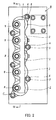
FIG. 1 is a front view of a cap provided on a valve main body. -
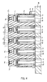
FIG. 2 is a side view of the cap provided on the valve main body. -
FIG. 3 is a sectional view ofFIG. 1 , taken along a III-III line. -
FIG. 4 is a sectional view ofFIG. 2 , taken along a IV-IV line. - Referring to
FIGS. 1 to 4 , an embodiment of the present invention will be described. - As shown in
FIG. 4 , a plurality of spools S are provided in a valve main body B to be free to slide. A single cap C in which a plurality ofpilot chambers 1 corresponding respectively to the spools S are formed is fixed to the valve main body B. Outer shapes of locations of the cap C corresponding to therespective pilot chambers 1 are set as cylindrical projectingportions 2. A projectingportion 3 is molded integrally with an outer side (a left side end inFIG. 1 ) of thecylindrical projecting portion 2. - As shown in
FIG. 3 , a plurality of boltingportions 4 for fixing the cap C to the valve main body B are formed in an outer peripheral part of the cap C in a diagonally opposed manner such that therespective pilot chambers 1 are sandwiched there between. At least one of the boltingportions 4 is formed in a position shared byadjacent pilot chambers 1. The cap C is fixed to the valve main body B by passingbolts 5 through the boltingportions 4. By providing the boltingportions 4 in a diagonally opposed manner such that thepilot chamber 1 is sandwiched there between, the number of boltingportions 4 can be reduced in comparison with a case where a pair of boltingportions 4 is provided for eachpilot chamber 1, for example. In so doing, the number ofbolts 5 can also be reduced, enabling a reduction in cost. - As shown in
FIG. 4 , aspool end 6 is provided on an extension of the axis of the spool S so as to face the interior of thepilot chamber 1. Aspring 7 that exerts a spring force on the spool S extends along thespool end 6. By providing thespring 7 to extend along thespool end 6, when a pilot pressure acts on thepilot chamber 1, the spring force of thespring 7 can be exerted on the spool S with stability. - A pilot
pressure introduction port 8 for introducing the pilot pressure into thepilot chamber 1 is formed in the projectingportion 3. Further, a maximumpressure introduction passage 9 is formed in a straight line through the projectingportions 3 so as to penetrate in an orthogonal direction to the axes of the spools S, or in other words an arrangement direction of the pilot chambers (seeFIG. 3 ). - The maximum
pressure introduction passage 9 communicates with therespective pilot chambers 1 via connectingpassages 10. The connectingpassages 10 are formed in an orthogonal direction to the maximumpressure introduction passage 9. More specifically, each connectingpassage 10 is constituted by a first connecting portion 10a formed along the axis of the spool S, and a second connecting portion 10b formed between the first connecting portion 10a and the maximumpressure introduction passage 9 to be orthogonal to the first connecting portion 10a. - The first connecting portion 10a connects the
pilot chamber 1 to the second connecting portion 10b, and the second connecting portion 10b connects the first connecting portion 10a to the maximumpressure introduction passage 9. Hence, thepilot chamber 1 and the maximumpressure introduction passage 9 communicate via the first and second connecting passages 10a, 10b. The first connecting portion 10a is formed in a position that avoids a center of thepilot chamber 1. -
Selection valves 11 for selecting a maximum pilot pressure amongpredetermined pilot chambers 1 are incorporated respectively into the second connecting portions 10b. Theselection valve 11 is constituted by a plug 11a, apoppet 11b, and a spring 11c provided between the plug 11a and thepoppet 11b in order to exert a spring force on thepoppet 11b. - A pressure in a
predetermined pilot chamber 1, introduced from the first connecting portion 10a, acts on one side of theselection valve 11, and a pressure in the maximumpressure introduction passage 9 acts on another side. Communication between the first connecting portion 10a and the second connecting portion 10b is normally blocked by an action of the spring force of the spring 11c. However, when a pressure on the first connecting portion 10a side becomes higher than a pressure on the second connecting portion 10b side, or in other words the pressure in the maximumpressure introduction passage 9, thepoppet 11b moves against the spring force of the spring 11c such that the first connecting portion 10a and the second connecting portion 10b communicate with each other. In other words, theselection valve 11 is configured such that when the pressure in thepilot chamber 1 is higher than the pressure in the maximumpressure introduction passage 9, the pressure in thepilot chamber 1 is led into the maximumpressure introduction passage 9. - The
selection valve 11 is incorporated from a side face of the cap C in a direction that intersects the axis of the spool S. When, on the other hand, the selection valve is incorporated in an axial direction of the spool, as in the conventional apparatus, an axial direction length of spool increases. In this embodiment, however, theselection valve 11 is incorporated in a direction that intersects the axis of the spool S, and therefore, in contrast to the related art, the axial direction length does not increase. - Further, since the
selection valve 11 is incorporated in a direction that intersects the axis of the spool S, a replacement operation to replace only theselection valve 11, for example, can be performed easily. If theselection valve 11 were incorporated along the axis of the spool S, it would be necessary to remove the cap C temporarily from the valve main body B in order to replace theselection valve 11. By incorporating theselection valve 11 in a direction that intersects the axis of the spool S, however, theselection valve 11 can be replaced without removing the cap C from the main body B. - According to this embodiment, the highest pilot pressure among the
predetermined pilot chambers 1 is selected by theselection valve 11 and led to the maximumpressure introduction passage 9. The maximum pressure led to the maximumpressure introduction passage 9 is led from a penetrating end of the maximumpressure introduction passage 9 to another hydraulic device through a passage not shown in the figures, and then used to control the hydraulic device. - In this embodiment, the maximum
pressure introduction passage 9 is formed in the cap C, and there is therefore no need to provide a special oil pressure plate, as in the related art. As a result, the hydraulic control apparatus can be simplified in configuration and reduced in cost. - Further, the maximum
pressure introduction passage 9 is provided in the cap on an opposite side of thepilot chambers 1 to the valve main body B. In other words, the valve main body B is provided on one side of thepilot chambers 1, and the maximumpressure introduction passage 9 is provided on an opposite side of thepilot chambers 1 to the valve main body B. As a result, a reduction in size and an increase in design freedom can be achieved in comparison with a case such as that of the related art, in which the maximum pressure introduction passage is offset in an orthogonal direction to the axes of the spools S so as not to interfere with the pilot chambers. - Furthermore, the maximum
pressure introduction passage 9 penetrates the cap in a straight line in an orthogonal direction to the axes of the spools S, or in other words the arrangement direction of the pilot chambers. Therefore, pressure loss is small, and a cutting process for forming the maximumpressure introduction passage 9 is simple. - Moreover, in this embodiment, the first connecting portions 10a are formed in positions avoiding the centers of the respective pilot chambers formed in the cap C, and therefore spaces are formed in the projecting
portions 3 of the cap C. The maximumpressure introduction passage 9 can be formed in these spaces. - Embodiments of the present invention were described above, but the above embodiments are merely examples of applications of the present invention, and the technical scope of the present invention is not limited to the specific constitutions of the above embodiments.
- This application claims priority based on Japanese Patent Application No.
2012-245783
Claims (10)
- A hydraulic control apparatus having a plurality of pilot chambers, comprising:a plurality of spools incorporated into a valve main body;a cap provided on the valve main body;pilot chambers provided in the cap to correspond to the respective spools;a maximum pressure introduction passage which is provided in the cap, and to which a maximum pressure of the pilot chambers is led;connecting passages connecting the maximum pressure introduction passage to the respective pilot chambers; andselection valves provided in the connecting passages,wherein the maximum pressure of the respective pilot chambers is selected by the selection valve and led to the maximum pressure introduction passage,the valve main body is provided on one side of the pilot chambers, andthe maximum pressure introduction passage is provided on an opposite side of the pilot chambers to the valve main body.
- The hydraulic control apparatus as defined in Claim 1, wherein the selection valve is incorporated from a side face of the cap in a direction that intersects an axis of the spool.
- The hydraulic control apparatus as defined in Claim 1, wherein a plurality of caps constituting the pilot chambers are formed integrally.
- The hydraulic control apparatus as defined in Claim 3, wherein a plurality of bolting portions for fixing the cap to the valve main body are provided in the cap in a diagonally opposed manner such that the respective pilot chambers are sandwiched there between, and
at least one of the bolting portions is formed in a position that is shared by adjacent pilot chambers. - The hydraulic control apparatus as defined in Claim 1, wherein the maximum pressure introduction passage is formed in a straight line intersecting axes of the respective spools.
- The hydraulic control apparatus as defined in Claim 1, wherein the respective connecting passages are formed in an orthogonal direction to the maximum pressure introduction passage and provided in parallel.
- The hydraulic control apparatus as defined in Claim 1, wherein a pressure in the pilot chamber acts on one side of the selection valve, and a pressure in the maximum pressure introduction passage acts on another side, and
when the pressure in the pilot chamber is higher than the pressure in the maximum pressure introduction passage, the pressure in the pilot chamber is led to the maximum pressure introduction passage. - The hydraulic control apparatus as defined in Claim 5, wherein the maximum pressure introduction passage penetrates in an arrangement direction of the pilot chambers such that a maximum pressure among pilot pressures in the respective pilot chambers is extracted from a penetrating end thereof.
- The hydraulic control apparatus as defined in Claim 1, wherein the connecting passage includes a first connecting portion and a second connecting portion,
the first connecting portion is formed along the axis of the spool so as to connect the pilot chamber to the second connecting portion,
the second connecting portion is formed orthogonally to the first connecting portion so as to connect the first connecting portion to the maximum pressure introduction passage, and
the selection valve is provided in the second connecting portion. - The hydraulic control apparatus as defined in Claim 9, wherein a pilot pressure introduction port for introducing the pilot pressure into the pilot chamber is formed in the cap, and
the first connecting portion is formed in a position that avoids a center of the pilot chamber.
Applications Claiming Priority (2)
| Application Number | Priority Date | Filing Date | Title |
|---|---|---|---|
| JP2012245783A JP5511933B2 (en) | 2012-11-07 | 2012-11-07 | Hydraulic control device |
| PCT/JP2013/079204 WO2014073416A1 (en) | 2012-11-07 | 2013-10-29 | Hydraulic control device |
Publications (3)
| Publication Number | Publication Date |
|---|---|
| EP2863067A1 true EP2863067A1 (en) | 2015-04-22 |
| EP2863067A4 EP2863067A4 (en) | 2015-07-29 |
| EP2863067B1 EP2863067B1 (en) | 2016-09-21 |
Family
ID=50684525
Family Applications (1)
| Application Number | Title | Priority Date | Filing Date |
|---|---|---|---|
| EP13853940.8A Active EP2863067B1 (en) | 2012-11-07 | 2013-10-29 | Hydraulic control device |
Country Status (6)
| Country | Link |
|---|---|
| US (1) | US9353772B2 (en) |
| EP (1) | EP2863067B1 (en) |
| JP (1) | JP5511933B2 (en) |
| KR (1) | KR101541684B1 (en) |
| CN (1) | CN104508306B (en) |
| WO (1) | WO2014073416A1 (en) |
Families Citing this family (5)
| Publication number | Priority date | Publication date | Assignee | Title |
|---|---|---|---|---|
| DE102016120025B4 (en) * | 2016-10-20 | 2021-12-09 | Bürkert Werke GmbH | Multiple valve insert, multiple valve and valve arrangement |
| JP6889674B2 (en) * | 2018-03-09 | 2021-06-18 | Kyb株式会社 | Control valve |
| KR102072750B1 (en) | 2019-05-23 | 2020-03-02 | 이윤서 | Doublesided display system |
| JP7023268B2 (en) * | 2019-12-06 | 2022-02-21 | 川崎重工業株式会社 | Multi-control valve device |
| US20250092989A1 (en) * | 2023-09-20 | 2025-03-20 | Lincoln Industrial Corporation | Lubricant distribution system with valve mount |
Family Cites Families (10)
| Publication number | Priority date | Publication date | Assignee | Title |
|---|---|---|---|---|
| JPS6124803A (en) * | 1984-07-14 | 1986-02-03 | Hitachi Constr Mach Co Ltd | Hydraulic operating device |
| JP2843656B2 (en) * | 1990-07-16 | 1999-01-06 | 東芝機械株式会社 | Multiple hydraulic control valve |
| JP3763045B2 (en) * | 1995-10-03 | 2006-04-05 | ナブテスコ株式会社 | Shuttle valve mechanism for multiple directional control valves |
| KR100291438B1 (en) * | 1996-08-08 | 2001-06-01 | 세구찌 류이찌 | Hydrulic control system |
| JP3868650B2 (en) * | 1999-02-09 | 2007-01-17 | 株式会社小松製作所 | Hydraulic circuit, priority valve block and operation valve block assembly |
| JP2000266002A (en) * | 1999-03-17 | 2000-09-26 | Kayaba Ind Co Ltd | Hydraulic control device |
| JP4688598B2 (en) | 2005-07-20 | 2011-05-25 | カヤバ工業株式会社 | Hydraulic control device |
| US7415822B1 (en) * | 2005-07-21 | 2008-08-26 | Deere & Company | Load sense boost device |
| JP4994048B2 (en) * | 2007-01-18 | 2012-08-08 | カヤバ工業株式会社 | Hydraulic control device |
| JP4994049B2 (en) | 2007-01-18 | 2012-08-08 | カヤバ工業株式会社 | Hydraulic control device |
-
2012
- 2012-11-07 JP JP2012245783A patent/JP5511933B2/en active Active
-
2013
- 2013-10-29 KR KR1020157001063A patent/KR101541684B1/en not_active Expired - Fee Related
- 2013-10-29 WO PCT/JP2013/079204 patent/WO2014073416A1/en not_active Ceased
- 2013-10-29 EP EP13853940.8A patent/EP2863067B1/en active Active
- 2013-10-29 US US14/416,283 patent/US9353772B2/en active Active
- 2013-10-29 CN CN201380038393.9A patent/CN104508306B/en active Active
Also Published As
| Publication number | Publication date |
|---|---|
| EP2863067B1 (en) | 2016-09-21 |
| CN104508306B (en) | 2016-03-09 |
| EP2863067A4 (en) | 2015-07-29 |
| KR101541684B1 (en) | 2015-08-03 |
| CN104508306A (en) | 2015-04-08 |
| KR20150015045A (en) | 2015-02-09 |
| JP5511933B2 (en) | 2014-06-04 |
| WO2014073416A1 (en) | 2014-05-15 |
| US9353772B2 (en) | 2016-05-31 |
| US20150226236A1 (en) | 2015-08-13 |
| JP2014095399A (en) | 2014-05-22 |
Similar Documents
| Publication | Publication Date | Title |
|---|---|---|
| EP2863067B1 (en) | Hydraulic control device | |
| US10174771B2 (en) | Dual 4-port electromagnetic valve | |
| EP2687764A1 (en) | Control valve | |
| CN114729707B (en) | Multiple control valve device | |
| EP2687765B1 (en) | Control valve | |
| US11339888B2 (en) | Hydraulic valve system with a valve housing and method for manufacturing a valve housing | |
| JP6338428B2 (en) | Valve structure | |
| US10323661B2 (en) | Cylinder and adsorption separation device using the cylinder | |
| US20200208746A1 (en) | Hydraulic valve | |
| JP6355606B2 (en) | Valve structure in load sensing circuit | |
| JP4994048B2 (en) | Hydraulic control device | |
| US10036468B2 (en) | Hydraulic control system | |
| KR102538807B1 (en) | spool valve | |
| JP2016109163A (en) | Hydraulic circuit | |
| JP5822232B2 (en) | Switching valve | |
| KR200483733Y1 (en) | hydraulic oil block valve | |
| EP3594510B1 (en) | Control valve | |
| JP2021120588A (en) | Multiple control valve unit |
Legal Events
| Date | Code | Title | Description |
|---|---|---|---|
| PUAI | Public reference made under article 153(3) epc to a published international application that has entered the european phase |
Free format text: ORIGINAL CODE: 0009012 |
|
| 17P | Request for examination filed |
Effective date: 20150113 |
|
| AK | Designated contracting states |
Kind code of ref document: A1 Designated state(s): AL AT BE BG CH CY CZ DE DK EE ES FI FR GB GR HR HU IE IS IT LI LT LU LV MC MK MT NL NO PL PT RO RS SE SI SK SM TR |
|
| AX | Request for extension of the european patent |
Extension state: BA ME |
|
| RA4 | Supplementary search report drawn up and despatched (corrected) |
Effective date: 20150629 |
|
| RIC1 | Information provided on ipc code assigned before grant |
Ipc: F15B 11/08 20060101ALI20150623BHEP Ipc: F15B 13/08 20060101ALI20150623BHEP Ipc: F15B 11/16 20060101ALI20150623BHEP Ipc: F16K 27/00 20060101ALI20150623BHEP Ipc: F15B 11/00 20060101AFI20150623BHEP Ipc: F16K 11/00 20060101ALI20150623BHEP |
|
| RAP1 | Party data changed (applicant data changed or rights of an application transferred) |
Owner name: KYB CORPORATION |
|
| DAX | Request for extension of the european patent (deleted) | ||
| REG | Reference to a national code |
Ref country code: DE Ref legal event code: R079 Ref document number: 602013012043 Country of ref document: DE Free format text: PREVIOUS MAIN CLASS: F15B0011000000 Ipc: F15B0013042000 |
|
| GRAP | Despatch of communication of intention to grant a patent |
Free format text: ORIGINAL CODE: EPIDOSNIGR1 |
|
| RIC1 | Information provided on ipc code assigned before grant |
Ipc: F15B 11/16 20060101ALI20160426BHEP Ipc: F16K 11/00 20060101ALI20160426BHEP Ipc: F15B 13/042 20060101AFI20160426BHEP Ipc: F16K 27/00 20060101ALI20160426BHEP Ipc: F15B 13/08 20060101ALI20160426BHEP Ipc: F16K 27/04 20060101ALI20160426BHEP |
|
| INTG | Intention to grant announced |
Effective date: 20160524 |
|
| GRAS | Grant fee paid |
Free format text: ORIGINAL CODE: EPIDOSNIGR3 |
|
| GRAA | (expected) grant |
Free format text: ORIGINAL CODE: 0009210 |
|
| AK | Designated contracting states |
Kind code of ref document: B1 Designated state(s): AL AT BE BG CH CY CZ DE DK EE ES FI FR GB GR HR HU IE IS IT LI LT LU LV MC MK MT NL NO PL PT RO RS SE SI SK SM TR |
|
| REG | Reference to a national code |
Ref country code: GB Ref legal event code: FG4D |
|
| REG | Reference to a national code |
Ref country code: CH Ref legal event code: EP |
|
| REG | Reference to a national code |
Ref country code: AT Ref legal event code: REF Ref document number: 831298 Country of ref document: AT Kind code of ref document: T Effective date: 20161015 |
|
| REG | Reference to a national code |
Ref country code: IE Ref legal event code: FG4D |
|
| REG | Reference to a national code |
Ref country code: DE Ref legal event code: R096 Ref document number: 602013012043 Country of ref document: DE |
|
| REG | Reference to a national code |
Ref country code: LT Ref legal event code: MG4D Ref country code: NL Ref legal event code: MP Effective date: 20160921 |
|
| PG25 | Lapsed in a contracting state [announced via postgrant information from national office to epo] |
Ref country code: LT Free format text: LAPSE BECAUSE OF FAILURE TO SUBMIT A TRANSLATION OF THE DESCRIPTION OR TO PAY THE FEE WITHIN THE PRESCRIBED TIME-LIMIT Effective date: 20160921 Ref country code: FI Free format text: LAPSE BECAUSE OF FAILURE TO SUBMIT A TRANSLATION OF THE DESCRIPTION OR TO PAY THE FEE WITHIN THE PRESCRIBED TIME-LIMIT Effective date: 20160921 Ref country code: NO Free format text: LAPSE BECAUSE OF FAILURE TO SUBMIT A TRANSLATION OF THE DESCRIPTION OR TO PAY THE FEE WITHIN THE PRESCRIBED TIME-LIMIT Effective date: 20161221 Ref country code: RS Free format text: LAPSE BECAUSE OF FAILURE TO SUBMIT A TRANSLATION OF THE DESCRIPTION OR TO PAY THE FEE WITHIN THE PRESCRIBED TIME-LIMIT Effective date: 20160921 |
|
| REG | Reference to a national code |
Ref country code: AT Ref legal event code: MK05 Ref document number: 831298 Country of ref document: AT Kind code of ref document: T Effective date: 20160921 |
|
| PG25 | Lapsed in a contracting state [announced via postgrant information from national office to epo] |
Ref country code: NL Free format text: LAPSE BECAUSE OF FAILURE TO SUBMIT A TRANSLATION OF THE DESCRIPTION OR TO PAY THE FEE WITHIN THE PRESCRIBED TIME-LIMIT Effective date: 20160921 Ref country code: LV Free format text: LAPSE BECAUSE OF FAILURE TO SUBMIT A TRANSLATION OF THE DESCRIPTION OR TO PAY THE FEE WITHIN THE PRESCRIBED TIME-LIMIT Effective date: 20160921 Ref country code: SE Free format text: LAPSE BECAUSE OF FAILURE TO SUBMIT A TRANSLATION OF THE DESCRIPTION OR TO PAY THE FEE WITHIN THE PRESCRIBED TIME-LIMIT Effective date: 20160921 Ref country code: GR Free format text: LAPSE BECAUSE OF FAILURE TO SUBMIT A TRANSLATION OF THE DESCRIPTION OR TO PAY THE FEE WITHIN THE PRESCRIBED TIME-LIMIT Effective date: 20161222 Ref country code: BE Free format text: LAPSE BECAUSE OF NON-PAYMENT OF DUE FEES Effective date: 20161031 |
|
| PG25 | Lapsed in a contracting state [announced via postgrant information from national office to epo] |
Ref country code: RO Free format text: LAPSE BECAUSE OF FAILURE TO SUBMIT A TRANSLATION OF THE DESCRIPTION OR TO PAY THE FEE WITHIN THE PRESCRIBED TIME-LIMIT Effective date: 20160921 Ref country code: EE Free format text: LAPSE BECAUSE OF FAILURE TO SUBMIT A TRANSLATION OF THE DESCRIPTION OR TO PAY THE FEE WITHIN THE PRESCRIBED TIME-LIMIT Effective date: 20160921 |
|
| PG25 | Lapsed in a contracting state [announced via postgrant information from national office to epo] |
Ref country code: SK Free format text: LAPSE BECAUSE OF FAILURE TO SUBMIT A TRANSLATION OF THE DESCRIPTION OR TO PAY THE FEE WITHIN THE PRESCRIBED TIME-LIMIT Effective date: 20160921 Ref country code: IS Free format text: LAPSE BECAUSE OF FAILURE TO SUBMIT A TRANSLATION OF THE DESCRIPTION OR TO PAY THE FEE WITHIN THE PRESCRIBED TIME-LIMIT Effective date: 20170121 Ref country code: AT Free format text: LAPSE BECAUSE OF FAILURE TO SUBMIT A TRANSLATION OF THE DESCRIPTION OR TO PAY THE FEE WITHIN THE PRESCRIBED TIME-LIMIT Effective date: 20160921 Ref country code: PL Free format text: LAPSE BECAUSE OF FAILURE TO SUBMIT A TRANSLATION OF THE DESCRIPTION OR TO PAY THE FEE WITHIN THE PRESCRIBED TIME-LIMIT Effective date: 20160921 Ref country code: BE Free format text: LAPSE BECAUSE OF FAILURE TO SUBMIT A TRANSLATION OF THE DESCRIPTION OR TO PAY THE FEE WITHIN THE PRESCRIBED TIME-LIMIT Effective date: 20160921 Ref country code: SM Free format text: LAPSE BECAUSE OF FAILURE TO SUBMIT A TRANSLATION OF THE DESCRIPTION OR TO PAY THE FEE WITHIN THE PRESCRIBED TIME-LIMIT Effective date: 20160921 Ref country code: ES Free format text: LAPSE BECAUSE OF FAILURE TO SUBMIT A TRANSLATION OF THE DESCRIPTION OR TO PAY THE FEE WITHIN THE PRESCRIBED TIME-LIMIT Effective date: 20160921 Ref country code: PT Free format text: LAPSE BECAUSE OF FAILURE TO SUBMIT A TRANSLATION OF THE DESCRIPTION OR TO PAY THE FEE WITHIN THE PRESCRIBED TIME-LIMIT Effective date: 20170123 Ref country code: CZ Free format text: LAPSE BECAUSE OF FAILURE TO SUBMIT A TRANSLATION OF THE DESCRIPTION OR TO PAY THE FEE WITHIN THE PRESCRIBED TIME-LIMIT Effective date: 20160921 Ref country code: BG Free format text: LAPSE BECAUSE OF FAILURE TO SUBMIT A TRANSLATION OF THE DESCRIPTION OR TO PAY THE FEE WITHIN THE PRESCRIBED TIME-LIMIT Effective date: 20161221 |
|
| REG | Reference to a national code |
Ref country code: CH Ref legal event code: PL |
|
| REG | Reference to a national code |
Ref country code: DE Ref legal event code: R097 Ref document number: 602013012043 Country of ref document: DE |
|
| PG25 | Lapsed in a contracting state [announced via postgrant information from national office to epo] |
Ref country code: IT Free format text: LAPSE BECAUSE OF FAILURE TO SUBMIT A TRANSLATION OF THE DESCRIPTION OR TO PAY THE FEE WITHIN THE PRESCRIBED TIME-LIMIT Effective date: 20160921 |
|
| REG | Reference to a national code |
Ref country code: IE Ref legal event code: MM4A |
|
| PLBE | No opposition filed within time limit |
Free format text: ORIGINAL CODE: 0009261 |
|
| REG | Reference to a national code |
Ref country code: FR Ref legal event code: ST Effective date: 20170630 |
|
| STAA | Information on the status of an ep patent application or granted ep patent |
Free format text: STATUS: NO OPPOSITION FILED WITHIN TIME LIMIT |
|
| PG25 | Lapsed in a contracting state [announced via postgrant information from national office to epo] |
Ref country code: DK Free format text: LAPSE BECAUSE OF FAILURE TO SUBMIT A TRANSLATION OF THE DESCRIPTION OR TO PAY THE FEE WITHIN THE PRESCRIBED TIME-LIMIT Effective date: 20160921 Ref country code: FR Free format text: LAPSE BECAUSE OF NON-PAYMENT OF DUE FEES Effective date: 20161121 Ref country code: CH Free format text: LAPSE BECAUSE OF NON-PAYMENT OF DUE FEES Effective date: 20161031 Ref country code: LI Free format text: LAPSE BECAUSE OF NON-PAYMENT OF DUE FEES Effective date: 20161031 |
|
| 26N | No opposition filed |
Effective date: 20170622 |
|
| PG25 | Lapsed in a contracting state [announced via postgrant information from national office to epo] |
Ref country code: LU Free format text: LAPSE BECAUSE OF NON-PAYMENT OF DUE FEES Effective date: 20161029 |
|
| PG25 | Lapsed in a contracting state [announced via postgrant information from national office to epo] |
Ref country code: SI Free format text: LAPSE BECAUSE OF FAILURE TO SUBMIT A TRANSLATION OF THE DESCRIPTION OR TO PAY THE FEE WITHIN THE PRESCRIBED TIME-LIMIT Effective date: 20160921 Ref country code: IE Free format text: LAPSE BECAUSE OF NON-PAYMENT OF DUE FEES Effective date: 20161029 |
|
| PGFP | Annual fee paid to national office [announced via postgrant information from national office to epo] |
Ref country code: GB Payment date: 20171019 Year of fee payment: 5 |
|
| PG25 | Lapsed in a contracting state [announced via postgrant information from national office to epo] |
Ref country code: HU Free format text: LAPSE BECAUSE OF FAILURE TO SUBMIT A TRANSLATION OF THE DESCRIPTION OR TO PAY THE FEE WITHIN THE PRESCRIBED TIME-LIMIT; INVALID AB INITIO Effective date: 20131029 |
|
| PG25 | Lapsed in a contracting state [announced via postgrant information from national office to epo] |
Ref country code: MK Free format text: LAPSE BECAUSE OF FAILURE TO SUBMIT A TRANSLATION OF THE DESCRIPTION OR TO PAY THE FEE WITHIN THE PRESCRIBED TIME-LIMIT Effective date: 20160921 Ref country code: CY Free format text: LAPSE BECAUSE OF FAILURE TO SUBMIT A TRANSLATION OF THE DESCRIPTION OR TO PAY THE FEE WITHIN THE PRESCRIBED TIME-LIMIT Effective date: 20160921 Ref country code: MC Free format text: LAPSE BECAUSE OF FAILURE TO SUBMIT A TRANSLATION OF THE DESCRIPTION OR TO PAY THE FEE WITHIN THE PRESCRIBED TIME-LIMIT Effective date: 20160921 Ref country code: MT Free format text: LAPSE BECAUSE OF NON-PAYMENT OF DUE FEES Effective date: 20161031 Ref country code: HR Free format text: LAPSE BECAUSE OF FAILURE TO SUBMIT A TRANSLATION OF THE DESCRIPTION OR TO PAY THE FEE WITHIN THE PRESCRIBED TIME-LIMIT Effective date: 20160921 |
|
| PG25 | Lapsed in a contracting state [announced via postgrant information from national office to epo] |
Ref country code: TR Free format text: LAPSE BECAUSE OF FAILURE TO SUBMIT A TRANSLATION OF THE DESCRIPTION OR TO PAY THE FEE WITHIN THE PRESCRIBED TIME-LIMIT Effective date: 20160921 Ref country code: AL Free format text: LAPSE BECAUSE OF FAILURE TO SUBMIT A TRANSLATION OF THE DESCRIPTION OR TO PAY THE FEE WITHIN THE PRESCRIBED TIME-LIMIT Effective date: 20160921 |
|
| GBPC | Gb: european patent ceased through non-payment of renewal fee |
Effective date: 20181029 |
|
| PG25 | Lapsed in a contracting state [announced via postgrant information from national office to epo] |
Ref country code: GB Free format text: LAPSE BECAUSE OF NON-PAYMENT OF DUE FEES Effective date: 20181029 |
|
| PGFP | Annual fee paid to national office [announced via postgrant information from national office to epo] |
Ref country code: DE Payment date: 20251021 Year of fee payment: 13 |