EP2863050A2 - Internal Combustion Engine Mounted with Combustion Pressure Sensor Incorporated Glow Plug and Sensor Nonincorporated Glow Plug - Google Patents
Internal Combustion Engine Mounted with Combustion Pressure Sensor Incorporated Glow Plug and Sensor Nonincorporated Glow Plug Download PDFInfo
- Publication number
- EP2863050A2 EP2863050A2 EP20140182250 EP14182250A EP2863050A2 EP 2863050 A2 EP2863050 A2 EP 2863050A2 EP 20140182250 EP20140182250 EP 20140182250 EP 14182250 A EP14182250 A EP 14182250A EP 2863050 A2 EP2863050 A2 EP 2863050A2
- Authority
- EP
- European Patent Office
- Prior art keywords
- voltage
- heater
- temperature
- section
- electricity supply
- Prior art date
- Legal status (The legal status is an assumption and is not a legal conclusion. Google has not performed a legal analysis and makes no representation as to the accuracy of the status listed.)
- Granted
Links
Images






Classifications
-
- F—MECHANICAL ENGINEERING; LIGHTING; HEATING; WEAPONS; BLASTING
- F02—COMBUSTION ENGINES; HOT-GAS OR COMBUSTION-PRODUCT ENGINE PLANTS
- F02P—IGNITION, OTHER THAN COMPRESSION IGNITION, FOR INTERNAL-COMBUSTION ENGINES; TESTING OF IGNITION TIMING IN COMPRESSION-IGNITION ENGINES
- F02P19/00—Incandescent ignition, e.g. during starting of internal combustion engines; Combination of incandescent and spark ignition
- F02P19/02—Incandescent ignition, e.g. during starting of internal combustion engines; Combination of incandescent and spark ignition electric, e.g. layout of circuits of apparatus having glowing plugs
- F02P19/028—Incandescent ignition, e.g. during starting of internal combustion engines; Combination of incandescent and spark ignition electric, e.g. layout of circuits of apparatus having glowing plugs the glow plug being combined with or used as a sensor
-
- F—MECHANICAL ENGINEERING; LIGHTING; HEATING; WEAPONS; BLASTING
- F02—COMBUSTION ENGINES; HOT-GAS OR COMBUSTION-PRODUCT ENGINE PLANTS
- F02P—IGNITION, OTHER THAN COMPRESSION IGNITION, FOR INTERNAL-COMBUSTION ENGINES; TESTING OF IGNITION TIMING IN COMPRESSION-IGNITION ENGINES
- F02P19/00—Incandescent ignition, e.g. during starting of internal combustion engines; Combination of incandescent and spark ignition
- F02P19/02—Incandescent ignition, e.g. during starting of internal combustion engines; Combination of incandescent and spark ignition electric, e.g. layout of circuits of apparatus having glowing plugs
- F02P19/021—Incandescent ignition, e.g. during starting of internal combustion engines; Combination of incandescent and spark ignition electric, e.g. layout of circuits of apparatus having glowing plugs characterised by power delivery controls
- F02P19/023—Individual control of the glow plugs
-
- F—MECHANICAL ENGINEERING; LIGHTING; HEATING; WEAPONS; BLASTING
- F23—COMBUSTION APPARATUS; COMBUSTION PROCESSES
- F23Q—IGNITION; EXTINGUISHING-DEVICES
- F23Q7/00—Incandescent ignition; Igniters using electrically-produced heat, e.g. lighters for cigarettes; Electrically-heated glowing plugs
- F23Q7/001—Glowing plugs for internal-combustion engines
-
- G—PHYSICS
- G01—MEASURING; TESTING
- G01L—MEASURING FORCE, STRESS, TORQUE, WORK, MECHANICAL POWER, MECHANICAL EFFICIENCY, OR FLUID PRESSURE
- G01L23/00—Devices or apparatus for measuring or indicating or recording rapid changes, such as oscillations, in the pressure of steam, gas, or liquid; Indicators for determining work or energy of steam, internal-combustion, or other fluid-pressure engines from the condition of the working fluid
- G01L23/08—Devices or apparatus for measuring or indicating or recording rapid changes, such as oscillations, in the pressure of steam, gas, or liquid; Indicators for determining work or energy of steam, internal-combustion, or other fluid-pressure engines from the condition of the working fluid operated electrically
-
- G—PHYSICS
- G01—MEASURING; TESTING
- G01L—MEASURING FORCE, STRESS, TORQUE, WORK, MECHANICAL POWER, MECHANICAL EFFICIENCY, OR FLUID PRESSURE
- G01L23/00—Devices or apparatus for measuring or indicating or recording rapid changes, such as oscillations, in the pressure of steam, gas, or liquid; Indicators for determining work or energy of steam, internal-combustion, or other fluid-pressure engines from the condition of the working fluid
- G01L23/26—Details or accessories
-
- G—PHYSICS
- G01—MEASURING; TESTING
- G01M—TESTING STATIC OR DYNAMIC BALANCE OF MACHINES OR STRUCTURES; TESTING OF STRUCTURES OR APPARATUS, NOT OTHERWISE PROVIDED FOR
- G01M15/00—Testing of engines
- G01M15/04—Testing internal-combustion engines
- G01M15/08—Testing internal-combustion engines by monitoring pressure in cylinders
-
- F—MECHANICAL ENGINEERING; LIGHTING; HEATING; WEAPONS; BLASTING
- F23—COMBUSTION APPARATUS; COMBUSTION PROCESSES
- F23Q—IGNITION; EXTINGUISHING-DEVICES
- F23Q7/00—Incandescent ignition; Igniters using electrically-produced heat, e.g. lighters for cigarettes; Electrically-heated glowing plugs
- F23Q7/001—Glowing plugs for internal-combustion engines
- F23Q2007/002—Glowing plugs for internal-combustion engines with sensing means
Definitions
- the present invention relates to an internal combustion engine in which a combustion pressure sensor incorporated glow plug is mounted to one or more of a plurality of cylinders of an engine body, and a sensor nonincorporated glow plug having no pressure sensor is mounted to each of the remaining cylinders.
- a known combustion pressure sensor incorporated glow plug is a glow plug which assists in start-up of an internal combustion engine such as a diesel engine and into which a pressure sensor is incorporated for detecting combustion pressure in a combustion chamber of the internal combustion engine (refer to, for example, Patent Document 1).
- a heater is disposed within a housing in an axially movable condition. An axial movement of the heater resulting from variation in combustion pressure is transmitted to a pressure sensor, thereby detecting combustion pressure within the combustion chamber of the internal combustion engine.
- the internal combustion engine (engine body) has a plurality of cylinders, such as four or six cylinders.
- a combustion pressure sensor incorporated glow plug may be used in the internal combustion engine such that the combustion pressure sensor incorporated glow plug is mounted to one or more of a plurality of cylinders, whereas an ordinary glow plug (hereinafter, may be called a sensor nonincorporated glow plug) having no pressure sensor (combustion pressure sensor) is mounted to each of the remaining cylinders.
- Patent Document 1 Japanese Patent Application Laid-Open ( kokai ) No. 2012-177483
- the same control is conducted on the cylinders regardless of existence of the combustion pressure sensor such that the heaters are pulse-energized at the same duty ratio without individually controlling the cylinders according to whether or not the combustion pressure incorporated glow plug is provided.
- the combustion pressure sensor incorporated glow plug and the sensor nonincorporated glow plug differ in a heater energization characteristic. Specifically, even when the same voltage is applied to the glow plugs, the respective heaters generate heat of different temperatures.
- the ECU applies electricity to the two types of glow plugs; i.e., the sensor incorporated and nonincorporated glow plugs, at the same duty ratio (effective applied voltage), the sensor incorporated and nonincorporated glow plugs may differ in heater temperature; as a result, the cylinders are apt to differ in a glow plug action of assisting in start-up.
- the present invention has been conceived in view of the above problem, and an object of the present invention is to provide an internal combustion engine in which a combustion pressure sensor incorporated glow plug is mounted to one or more of a plurality of cylinders of an engine body, whereas a sensor nonincorporated glow plug having no pressure sensor is mounted to each of the remaining cylinders and in which, when the same effective voltage is applied to overall structures each comprising of a cable and a glow plug, the occurrence of a difference in heater temperature among the cylinders is restrained.
- a mode of the present invention provides an internal combustion engine comprising an engine body having a plurality of cylinders; a combustion pressure sensor incorporated glow plug mounted to one or more of the plurality of cylinders and having a first heater which generates heat through energization, and a pressure sensor for detecting combustion pressure of the cylinder(s) to which the combustion pressure sensor incorporated glow plug is mounted; a first electricity supply cable including a first electricity supply line for supplying electricity from an external power supply to the first heater of the combustion pressure sensor incorporated glow plug; a sensor nonincorporated glow plug mounted to each of the remaining cylinders to which the combustion pressure sensor incorporated glow plug is not mounted, and having a second heater which generates heat through energization and no pressure sensor; and a second electricity supply cable including a second electricity supply line for supplying electricity from the external power supply to the second heater of the sensor nonincorporated glow plug.
- a first plug regression line is drawn from a first plug voltage vs. temperature characteristic indicative of a relation, within a temperature range of 950°C to 1,350°C, between a first plug voltage applied to the combustion pressure sensor incorporated glow plug and a first heater temperature indicative of a temperature of heat generated by the first heater
- a second plug regression line is drawn from a second plug voltage vs.
- a first voltage is the first plug voltage at which the first heater temperature becomes a predetermined temperature within the temperature range on the first plug regression line
- a second voltage is the second plug voltage at which the second heater temperature becomes the same predetermined temperature on the second plug regression line
- a first-second plug voltage difference is a difference at the predetermined temperature between the first voltage and the second voltage
- the first plug regression line and the second plug regression line are in such a relation that, at any predetermined temperature within the temperature range, the second voltage is lower than the first voltage.
- Resistance of the second electricity supply line is greater than resistance of the first electricity supply line.
- a first section regression line is drawn from a first section voltage vs. temperature characteristic indicative of a relation, within the temperature range, between a first section voltage applied to a first section comprising the combustion pressure sensor incorporated glow plug and the first electricity supply cable, and the first heater temperature
- a second section regression line is drawn from a second section voltage vs.
- a third voltage is the first section voltage at which the first heater temperature becomes the predetermined temperature on the first section regression line
- a fourth voltage is the second section voltage at which the second heater temperature becomes the same predetermined temperature on the second section regression line
- an overall voltage deviation is an absolute value of a difference at the predetermined temperature between the third voltage and the fourth voltage
- the first section regression line and the second section regression line are in such a relation that, at any predetermined temperature within the temperature range, the overall voltage deviation is smaller than the first-second plug voltage difference.
- the first plug regression line and the second plug regression line are in such a relation that, at any heater temperature within a temperature range of 950°C to 1,350°C, the second voltage is lower than the first voltage.
- the combustion pressure sensor incorporated glow plug and the sensor nonincorporated glow plug do not match in a heater energization characteristic indicative of the relation between voltages (first plug voltage and second plug voltage) applied to the glow plugs and temperatures of heat generated by the heaters (first heater temperature and second heater temperature). Also, in the case where the first heater temperature and the second heater temperature are to have the same temperature, a required second plug voltage is lower than a required first plug voltage. In other words, in the case where the first plug voltage and the second plug voltage applied to the respective glow plugs have the same voltage, the second heater temperature becomes higher than the first heater temperature.
- resistance of the second electricity supply line of the second electricity supply cable is rendered greater than resistance of the first electricity supply line of the first electricity supply cable. Accordingly, at any heater temperature within the aforementioned temperature range, the first section regression line and the second section regression line are in such a relation that the overall voltage deviation is smaller than the first-second plug voltage difference. That is, deviation between the first section voltage and the second section voltage (absolute value of the difference between the two voltages) required for the first heater temperature and the second heater temperature to have the same temperature is smaller than the difference between the first plug voltage and the second plug voltage.
- resistance of the second electricity supply line is rendered greater than resistance of the first electricity supply line.
- a method of rendering resistance of the second electricity supply line greater than resistance of the first electricity supply line is to form the second electricity supply line from a material having specific resistance (electric resistivity, ⁇ m) higher than that of a material used to form the first electricity supply line.
- Other methods are to render the cross-sectional area of the second electricity supply line smaller than that of the first electricity supply line and to render the overall length of the second electricity supply line longer than that of the first electricity supply line.
- resistance of the second electricity supply line can be easily rendered greater than resistance of the first electricity supply line.
- Another mode of the present invention provides an internal combustion engine comprising an engine body having a plurality of cylinders; a combustion pressure sensor incorporated glow plug mounted to one or more of the plurality of cylinders and having a first heater which generates heat through energization, and a pressure sensor for detecting combustion pressure of the cylinder(s) to which the combustion pressure sensor incorporated glow plug is mounted; a first electricity supply cable including a first electricity supply line for supplying electricity from an external power supply to the first heater of the combustion pressure sensor incorporated glow plug; a sensor nonincorporated glow plug mounted to each of the remaining cylinders to which the combustion pressure sensor incorporated glow plug is not mounted, and having a second heater which generates heat through energization and no pressure sensor; and a second electricity supply cable including a second electricity supply line for supplying electricity from the external power supply to the second heater of the sensor nonincorporated glow plug.
- the combustion pressure sensor incorporated glow plug has a first electrically conductive member connected to the first electricity supply line to electrically connect the first electricity supply line to the first heater.
- the sensor nonincorporated glow plug has a second electrically conductive member connected to the second electricity supply line to electrically connect the second electricity supply line to the second heater. Assuming that a first residual section regression line is drawn from a first residual section voltage vs.
- a second residual section regression line is drawn from a second residual section voltage vs.
- a first voltage is the first residual section voltage at which the first heater temperature becomes a predetermined temperature within the temperature range on the first residual section regression line
- a second voltage is the second residual section voltage at which the second heater temperature becomes the same predetermined temperature on the second residual section regression line
- a first-second residual section voltage difference is a difference at the predetermined temperature between the first voltage and the second voltage
- the first residual section regression line and the second residual section regression line are in such a relation that, at any predetermined temperature within the temperature range, the second voltage is lower than the first voltage.
- a sum of resistance of the second electrically conductive member and resistance of the second electricity supply line is greater than a sum of resistance of the first electrically conductive member and resistance of the first electricity supply line.
- a first section regression line is drawn from a first section voltage vs. temperature characteristic indicative of a relation, within the temperature range, between a first section voltage applied to a first section comprising the combustion pressure sensor incorporated glow plug and the first electricity supply cable, and the first heater temperature
- a second section regression line is drawn from a second section voltage vs.
- a third voltage is the first section voltage at which the first heater temperature becomes the predetermined temperature on the first section regression line
- a fourth voltage is the second section voltage at which the second heater temperature becomes the same predetermined temperature on the second section regression line
- an overall voltage deviation is an absolute value of a difference at the predetermined temperature between the third voltage and the fourth voltage
- the first section regression line and the second section regression line are in such a relation that, at any predetermined temperature within the temperature range, the overall voltage deviation is smaller than the first-second residual section voltage difference.
- the first residual section regression line and the second residual section regression line are in such a relation that, at any heater temperature within a temperature range of 950°C to 1,350°C, the second voltage is lower than the first voltage.
- the combustion pressure sensor incorporated glow plug and the sensor nonincorporated glow plug do not match in a heater energization characteristic; specifically, in comparison of the first residual section encompassing the first heater and the second residual section encompassing the second heater, an energization characteristic of the first heater (the relation between the first residual section voltage and the first heater temperature) with respect to the first residual section and an energization characteristic of the second heater (the relation between the second residual section voltage and the second heater temperature) with respect to the second residual section do not match. Also, in the case where the first heater temperature and the second heater temperature are to have the same temperature, a required second residual section voltage is lower than a required first residual section voltage. In other words, in the case where the first residual section voltage and the second residual section voltage have the same voltage, the second heater temperature becomes higher than the first heater temperature.
- the sum of resistance of the second electrically conductive member and resistance of the second electricity supply line is rendered greater than the sum of resistance of the first electrically conductive member and resistance of the first electricity supply line. Accordingly, at any heater temperature within the aforementioned temperature range, the first section regression line and the second section regression line are in such a relation that the overall voltage deviation is smaller than the first-second residual section voltage difference. That is, deviation between the first section voltage and the second section voltage (absolute value of the difference between the two voltages) required for the first heater temperature and the second heater temperature to have the same temperature is smaller than the difference between the first residual section voltage and the second residual section voltage.
- the sum of resistance of the second electrically conductive member and resistance of the second electricity supply line is rendered greater than the sum of resistance of the first electrically conductive member and resistance of the first electricity supply line.
- a method of rendering the sum of resistance of the second electrically conductive member and resistance of the second electricity supply line greater than the sum of resistance of the first electrically conductive member and resistance of the first electricity supply line is not only to form the second electricity supply line from a material having specific resistance (electric resistivity) higher than that of a material used to form the first electricity supply line, but also to form the second electrically conductive member from a material having specific resistance (electric resistivity) higher than that of a material used to form the first electrically conductive member.
- a further method is to reduce the cross-sectional areas or to increase the overall lengths of the second electricity supply line and the second electrically conductive member for rendering the second electricity supply line and the second electrically conductive member greater in resistance than the first electricity supply line and the first electrically conductive member.
- the combustion pressure sensor incorporated glow plug has a tubular first housing which accommodates the first heater in such a manner that a forward end portion of the first heater protrudes from a forward end of the first housing;
- the first electrically conductive member includes a first external terminal disposed at a rear side and connected to the first electricity supply line and a rodlike first shaft inserted in the first housing and electrically connecting the first heater and the first external terminal;
- the sensor nonincorporated glow plug has a tubular second housing which accommodates the second heater in such a manner that a forward end portion of the second heater protrudes from a forward end of the second housing;
- the second electrically conductive member includes a second external terminal disposed at a rear side and connected to the second electricity supply line and a rodlike second shaft inserted in the second housing and electrically connecting the second heater and the second external terminal; and at least one of the following conditions is employed: resistance of the second shaft is greater than resistance of the first shaft, and resistance of the second electricity supply line is greater
- resistance of a second shaft is greater than resistance of a first shaft
- resistance of the second electricity supply line is greater than resistance of the first electricity supply line. That is, one of the following three conditions is employed: resistance of the second electricity supply line is greater than resistance of the first electricity supply line; resistance of the second shaft is greater than resistance of the first shaft; and resistance of the second electricity supply line is greater than resistance of the first electricity supply line, and resistance of the second shaft is greater than resistance of the first shaft.
- first shaft and the second shaft are major portions of the first electrically conductive member and the second electrically conductive member, respectively, and have a certain length and a certain diameter, differentiating resistances of the first and second shafts is relatively easy.
- resistance of the second electricity supply line greater than resistance of the first electricity supply line, or, in place of or in addition to this, rendering resistance of the second shaft greater than resistance of the first shaft, heater energization characteristics of overall structures each comprising a cable and a glow plug can be brought close to each other.
- a further mode of the present invention provides an internal combustion engine comprising an engine body having a plurality of cylinders; a combustion pressure sensor incorporated glow plug mounted to one or more of the plurality of cylinders and having a first heater which generates heat through energization, and a pressure sensor for detecting combustion pressure of the cylinder(s) to which the combustion pressure sensor incorporated glow plug is mounted; a first electricity supply cable including a first electricity supply line for supplying electricity from an external power supply to the first heater of the combustion pressure sensor incorporated glow plug; a sensor nonincorporated glow plug mounted to each of the remaining cylinders to which the combustion pressure sensor incorporated glow plug is not mounted, and having a second heater which generates heat through energization, and no pressure sensor; and a second electricity supply cable including a second electricity supply line for supplying electricity from the external power supply to the second heater of the sensor nonincorporated glow plug.
- a first plug regression line is drawn from a first plug voltage vs. temperature characteristic indicative of a relation, within a temperature range of 950°C to 1,350°C, between a first plug voltage applied to the combustion pressure sensor incorporated glow plug and a first heater temperature indicative of a temperature of heat generated by the first heater
- a second plug regression line is drawn from a second plug voltage vs.
- a first voltage is the first plug voltage at which the first heater temperature becomes a predetermined temperature within the temperature range on the first plug regression line
- a second voltage is the second plug voltage at which the second heater temperature becomes the same predetermined temperature on the second plug regression line
- a second-first plug voltage difference is a difference at the predetermined temperature between the second voltage and the first voltage
- the first plug regression line and the second plug regression line are in such a relation that, at any predetermined temperature within the temperature range, the second voltage is higher than the first voltage.
- Resistance of the second electricity supply line is smaller than resistance of the first electricity supply line.
- a first section regression line is drawn from a first section voltage vs. temperature characteristic indicative of a relation, within the temperature range, between a first section voltage applied to a first section comprising the combustion pressure sensor incorporated glow plug and the first electricity supply cable, and the first heater temperature
- a second section regression line is drawn from a second section voltage vs.
- a third voltage is the first section voltage at which the first heater temperature becomes the predetermined temperature on the first section regression line
- a fourth voltage is the second section voltage at which the second heater temperature becomes the same predetermined temperature on the second section regression line
- an overall voltage deviation is an absolute value of a difference at the predetermined temperature between the fourth voltage and the third voltage
- the first section regression line and the second section regression line are in such a relation that, at any predetermined temperature within the temperature range, the overall voltage deviation is smaller than the second-first plug voltage difference.
- the first plug regression line and the second plug regression line are in such a relation that, at any heater temperature within a temperature range of 950°C to 1,350°C, the second voltage is higher than the first voltage.
- the relation between the first plug voltage vs. first heater temperature characteristic and the second plug voltage vs. second heater temperature characteristic is opposite that of the aforementioned internal combustion engine; specifically, in the case where the first heater temperature and the second heater temperature are to have the same temperature, a required second plug voltage is higher than a required first plug voltage. In other words, in the case where the first plug voltage and the second plug voltage applied to the respective glow plugs have the same voltage, the second heater temperature becomes lower than the first heater temperature.
- resistance of the second electricity supply line of the second electricity supply cable is rendered smaller than resistance of the first electricity supply line of the first electricity supply cable. Accordingly, at any heater temperature within the aforementioned temperature range, the first section regression line and the second section regression line are in such a relation that the overall voltage deviation is smaller than the second-first plug voltage difference. That is, deviation between the second section voltage and the first section voltage (absolute value of the difference between the two voltages) required for the first heater temperature and the second heater temperature to have the same temperature is smaller than the difference between the second plug voltage and the first plug voltage.
- resistance of the second electricity supply line is rendered smaller than resistance of the first electricity supply line.
- a still further mode of the present invention provides an internal combustion engine comprising an engine body having a plurality of cylinders; a combustion pressure sensor incorporated glow plug mounted to one or more of the plurality of cylinders and having a first heater which generates heat through energization, and a pressure sensor for detecting combustion pressure of the cylinder(s) to which the combustion pressure sensor incorporated glow plug is mounted; a first electricity supply cable including a first electricity supply line for supplying electricity from an external power supply to the first heater of the combustion pressure sensor incorporated glow plug; a sensor nonincorporated glow plug mounted to each of the remaining cylinders to which the combustion pressure sensor incorporated glow plug is not mounted, and having a second heater which generates heat through energization and no pressure sensor; and a second electricity supply cable including a second electricity supply line for supplying electricity from the external power supply to the second heater of the sensor nonincorporated glow plug.
- the combustion pressure sensor incorporated glow plug has a first electrically conductive member connected to the first electricity supply line to electrically connect the first electricity supply line to the first heater.
- the sensor nonincorporated glow plug has a second electrically conductive member connected to the second electricity supply line to electrically connect the second electricity supply line to the second heater. Assuming that a first residual section regression line is drawn from a first residual section voltage vs.
- a second residual section regression line is drawn from a second residual section voltage vs.
- a first voltage is the first residual section voltage at which the first heater temperature becomes a predetermined temperature within the temperature range on the first residual section regression line
- a second voltage is the second residual section voltage at which the second heater temperature becomes the same predetermined temperature on the second residual section regression line
- a second-first residual section voltage difference is a difference at the predetermined temperature between the second voltage and the first voltage
- a sum of resistance of the second electrically conductive member and resistance of the second electricity supply line is smaller than a sum of resistance of the first electrically conductive member and resistance of the first electricity supply line.
- a first section regression line is drawn from a first section voltage vs. temperature characteristic indicative of a relation, within the temperature range, between a first section voltage applied to a first section comprising the combustion pressure sensor incorporated glow plug and the first electricity supply cable, and the first heater temperature
- a second section regression line is drawn from a second section voltage vs.
- a third voltage is the first section voltage at which the first heater temperature becomes the predetermined temperature on the first section regression line
- a fourth voltage is the second section voltage at which the second heater temperature becomes the same predetermined temperature on the second section regression line
- an overall voltage deviation is an absolute value of a difference at the predetermined temperature between the fourth voltage and the third voltage
- the first section regression line and the second section regression line are in such a relation that, at any predetermined temperature within the temperature range, the overall voltage deviation is smaller than the second-first residual section voltage difference.
- the first residual section regression line and the second residual section regression line are in such a relation that, at any heater temperature within a temperature range of 950°C to 1,350°C, the second voltage is higher than the first voltage.
- the relation between the first residual section voltage vs. first heater temperature characteristic and the second residual section voltage vs. second heater temperature characteristic is opposite that of the aforementioned internal combustion engine; specifically, in the case where the first heater temperature and the second heater temperature are to have the same temperature, a required second residual section voltage is higher than a required first residual section voltage. In other words, in the case where the first residual section voltage and the second residual section voltage have the same voltage, the second heater temperature becomes lower than the first heater temperature.
- the sum of resistance of the second electrically conductive member and resistance of the second electricity supply line is rendered smaller than the sum of resistance of the first electrically conductive member and resistance of the first electricity supply line.
- the first section regression line and the second section regression line are in such a relation that the overall voltage deviation is smaller than the second-first residual section voltage difference. That is, deviation between the second section voltage and the first section voltage (absolute value of the difference between the two voltages) required for the first heater temperature and the second heater temperature to have the same temperature is smaller than the difference between the second residual section voltage and the first residual section voltage.
- the sum of resistance of the second electrically conductive member and resistance of the second electricity supply line is rendered smaller than the sum of resistance of the first electrically conductive member and resistance of the first electricity supply line.
- the combustion pressure sensor incorporated glow plug has a tubular first housing which accommodates the first heater in such a manner that a forward end portion of the first heater protrudes from a forward end of the first housing;
- the first electrically conductive member includes a first external terminal disposed at a rear side and connected to the first electricity supply line and a rodlike first shaft inserted in the first housing and electrically connecting the first heater and the first external terminal;
- the sensor nonincorporated glow plug has a tubular second housing which accommodates the second heater in such a manner that a forward end portion of the second heater protrudes from a forward end of the second housing;
- the second electrically conductive member includes a second external terminal disposed at a rear side and connected to the second electricity supply line and a rodlike second shaft inserted in the second housing and electrically connecting the second heater and the second external terminal; and at least one of the following conditions is employed: resistance of the second shaft is smaller than resistance of the first shaft, and resistance of the second electricity supply line is
- resistance of a second shaft is smaller than resistance of a first shaft
- resistance of the second electricity supply line is smaller than resistance of the first electricity supply line. That is, one of the following three conditions is employed: resistance of the second electricity supply line is smaller than resistance of the first electricity supply line; resistance of the second shaft is smaller than resistance of the first shaft; and resistance of the second electricity supply line is smaller than resistance of the first electricity supply line, and resistance of the second shaft is smaller than resistance of the first shaft.
- first shaft and the second shaft are major portions of the first electrically conductive member and the second electrically conductive member, respectively, and have a certain length and a certain diameter, differentiating resistances of the first and second shafts is relatively easy.
- resistance of the second electricity supply line smaller than resistance of the first electricity supply line, or, in place of or in addition to this, rendering resistance of the second shaft smaller than resistance of the first shaft, heater energization characteristics of overall structures each comprising a cable and a glow plug can be brought close to each other.
- FIG. 1 shows the glow plug mounting structure of an internal combustion engine 1 according to the first embodiment.
- the internal combustion engine 1 is a 4-cylinder diesel engine equipped with an engine body 10 having four cylinders 11A, 11B, 11C, and 11D.
- the cylinder 11A has a combustion pressure sensor incorporated glow plug 20A mounted thereto and having a pressure sensor 200 (see FIGS. 2 and 3 ) for detecting combustion pressure of the cylinder 11A.
- the remaining three cylinders 11B to 11D each have a sensor nonincorporated glow plug 20B mounted thereto and having no pressure sensor.
- FIG. 2 is a general view showing the combustion pressure sensor incorporated glow plug 20A (hereinafter, referred to merely as the sensor incorporated plug 20A) to be mounted to the cylinder 11A
- FIG. 3 is a fragmentary enlarged sectional view of the sensor incorporated plug 20A
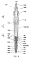
- FIG. 4 is a general view showing a sensor nonincorporated glow plug 20B (hereinafter, referred to merely as the plug 20B) to be mounted to the cylinders 11B to 11D. As shown in FIG.
- the sensor incorporated plug 20A and the plugs 20B are mounted to the cylinders 11A to 11D, respectively, in such a condition that heater forward end portions 130As and 130Bs of their heaters 130A and 130B protrude into combustion chambers 10a to 10d, respectively.
- the sensor incorporated plug 20A and the plugs 20B are utilized as heat sources for assisting in ignition at the time of engine start-up. Additionally, the sensor incorporated plug 20A detects combustion pressure in the combustion chamber 10a of the cylinder 11A to which the same is mounted.
- the plug 20B having no pressure sensor will be described with respect to overall structure with reference to FIG. 4 .
- the plug 20B includes a metallic shell 110B, a heater 130B, a shaft 120B, a ring member 140, an outer tube 150B, and a pin terminal 160B.
- the metallic shell 110B and the outer tube 150B are united together, thereby forming a housing 100B of the plug 20B.
- a side toward the heater 130B (lower side in FIG. 4 ) of an axial direction HJ2 along an axial line AX2 of the plug 20B is referred to as a forward side GS2 of the plug 20B, and an opposite side (upper side in FIG. 4 ) is referred to as a rear side GK2 of the plug 20B.
- the metallic shell 110B is a major portion of the housing 100B; is formed of a metal material; and assumes a tubular form extending in the axial direction HJ2 from its metallic-shell forward end portion 110Bs to a metallic-shell rear end portion 110Bk.
- the metallic shell 110B has an axial hole 110Bh extending therethrough.
- the metallic shell 110B has an externally threaded portion 111B adapted for mounting use and formed on its outer circumferential surface at the rear side GK2.
- the shaft 120B is formed of carbon steel and assumes a rodlike form extending in the axial direction HJ2 from its shaft forward end portion 120Bs to its shaft rear end portion 120Bk.
- the shaft 120B is inserted into the metallic shell 110B in such a condition that the shaft rear end portion 120Bk protrudes from the metallic-shell rear end portion 110Bk toward the rear side GK2.
- the shaft forward end portion 120Bs is fitted into a ring rear end portion 140k, which will be described later, of the ring member 140.
- the heater 130B assumes a rodlike form extending in the axial direction HJ2 from its heater forward end portion 130Bs to its heater rear end portion 130Bk.
- the heater 130B is inserted into the metallic shell 110B in such a condition that the heater forward end portion 130Bs, which generates heat through energization, protrudes from the metallic-shell forward end portion 110Bs toward the forward side GS2.
- the heater 130B is a ceramic heater having the following structure: a heat-generating resistor 132B formed of electrically conductive ceramic (specifically, silicon-nitride ceramic which contains tungsten carbide as an electrically conductive component) is embedded in a rodlike insulating substrate 131B formed of insulating ceramic (specifically, silicon-nitride ceramic).
- the heat-generating resistor 132B has a heat-generating portion 133B and a pair of lead portions 135B and 136B.
- the heat-generating portion 133B is bent to a shape resembling the letter U and is disposed in the heater forward end portion 130Bs.
- the two lead portions 135B and 136B are connected to the respective opposite ends of the U-shaped heat-generating portion 133B and extends to the rear end surface of the heater rear end portion 130Bk.
- the lead portions 135B and 136B have electrode lead-out portions 137B and 138B, respectively. Specifically, the lead portion 135B has the electrode lead-out portion 137B formed at the heater rear end portion 130Bk.
- the electrode lead-out portion 137B is exposed at the outer circumference of the heater rear end portion 130Bk and is electrically connected to the ring member 140, which will be described next. Also, the lead portion 136B has the electrode lead-out portion 138B formed on the forward side GS2 with respect to the electrode lead-out portion 137B. The electrode lead-out portion 138B is exposed at the outer circumference of the heater 130B and is connected to the outer tube 150B, which will be described later.
- the ring member 140 is formed of stainless steel and assumes a thin-walled cylindrical form extending in the axial direction HJ2 from its ring forward end portion 140s to its ring rear end portion 140k.
- the ring member 140 is disposed within the metallic shell 110B and connects the shaft 120B and the heater 130B.
- the heater rear end portion 130Bk of the heater 130B is press-fitted into the ring forward end portion 140s of the ring member 140; as a result, the electrode lead-out portion 137B of the heater 130B comes into contact with the ring member 140 from inside, whereby an electrical connection is established therebetween.
- the shaft forward end portion 120Bs of the shaft 120B is press-fitted into the ring rear end portion 140k of the ring member 140, whereby an electrical connection is established between the ring member 140 and the shaft 120B. Furthermore, the ring member 140 and the shaft 120B are fixedly welded to each other.
- the outer tube 150B is formed of stainless steel and assumes a tubular form extending in the axial direction HJ2 from its outer-tube forward end portion 150Bs to its outer-tube rear end portion 150Bk.
- the heater 130B is press-fitted into the outer tube 150B in such a condition that the heater forward end portion 130Bs protrudes from the outer-tube forward end portion 150Bs toward the forward side GS2 and that the heater rear end portion 130Bk protrudes from the outer-tube rear end portion 150Bk toward the rear side GK2.
- the electrode lead-out portion 138B of the heater 130B comes into contact with the outer tube 150B from inside, whereby the outer tube 150B and the electrode lead-out portion 138B are electrically connected to each other.
- the outer-tube rear end portion 150Bk of the outer tube 150B is reduced in diameter and is fitted into the metallic-shell forward end portion 110Bs of the metallic shell 110B.
- the outer tube 150B and the metallic shell 110B are fixedly welded to each other.
- the metallic shell 110B and the outer tube 150B are integrated with each other, thereby forming the housing 100B.
- the heater 130B is held to the metallic-shell forward end portion 110Bs of the metallic shell 110B through the outer tube 150B.
- the pin terminal 160B is fixed to the shaft rear-end portion 120Bk of the shaft 120B by circumferential crimping. As shown in FIG. 1 , a connector cap 80 connected to an electricity supply cable 300B including an electricity supply line 310B is fitted to the pin terminal 160B, whereby the pin terminal 160B is connected to the electricity supply line 310B of the electricity supply cable 300B.
- the heater 130B corresponds to the second heater in the present invention
- the housing 100B corresponds to the second housing.
- the pin terminal 160B corresponds to the second external terminal
- the shaft 120B corresponds to the second shaft.
- the electricity supply line 310B corresponds to the second electricity supply line
- the electricity supply cable 300B corresponds to the second electricity supply cable.
- the pin terminal 160B (second external terminal), the shaft 120B (second shaft), and the ring member 140 constitute a second electrically conductive member 40B which electrically connects the electricity supply line 310B (second electricity supply line) to the heater 130B (second heater) (see FIGS. 6 , 9 , 12 , and 15 ).
- a second residual section 50B is a section which remains after eliminating the second electrically conductive member 40B from the plug 20B and encompasses the heater 130B (second heater) (specifically, encompasses not only the heater 130B but also the housing 100B).
- the sensor incorporated plug 20A includes a metallic shell 110A, a shaft 120A, a heater 130A, a first ring member 141, a second ring member 142, a heater sheath 155, a forward end cap 150A, an inner tube 190, a membrane 170, a pressure sensor 200, a terminal assembly 250, and an external connection terminal 160A.
- the metallic shell 110A, and a flange portion 191 and a forward end portion 190s of the inner tube 190, and the forward end cap 150A are united together to form a housing 100A of the sensor incorporated plug 20A.
- the pressure sensor 200 includes not only a sensor body 210 but also a transmission sleeve 220, and an inner-tube body 192 of the inner tube 190 adapted to fix the sensor body 210 to the inside of the housing 100A (metallic shell 110A).
- a side toward the heater 130A (lower side in FIG. 2 ) of an axial direction HJ1 along an axial line AX1 of the sensor incorporated plug 20A is referred to as a forward side GS1 of the sensor incorporated plug 20A, and an opposite side (upper side in FIG. 2 ) is referred to as a rear side GK1 of the sensor incorporated plug 20A.
- the metallic shell 110A is a major portion of the housing 100A; is formed of a metal material; and assumes a tubular form extending in the axial direction HJ1 from its metallic-shell forward end portion 110As to a metallic-shell rear end portion 110Ak.
- the metallic shell 110A has an axial hole 110Ah formed therein.
- the metallic shell 110A has an externally threaded portion 111A adapted for mounting use and formed on its outer circumferential surface at the rear side GK1.
- the inner-tube body 192 of the inner tube 190 assumes a substantially cylindrical form and is disposed concentrically in the axial hole 110Ah of the metallic shell 110A at the forward side GS1 with respect to the axial direction HJ1.
- the inner-tube body 192 has the collar-like flange portion 191 protruding radially outward and formed at the forward side GS1 with respect to the axial direction HJ1.
- the flange portion 191 has the same outside diameter as that of the metallic-shell forward end portion 110As of the metallic shell 110A and partially constitutes the housing 100A.
- the flange portion 191 is welded to the metallic-shell forward end portion 110As of the metallic shell 110A.
- an annular outer circumferential portion 212 of the sensor body 210 is welded to a rear end portion 190k of the inner tube 190.
- the forward end cap 150A is formed of a metal material and has a cylindrical portion 151 formed at its rear side GK1.
- the cylindrical portion 151 is externally fitted to the forward end portion 190s of the inner tube 190 and is welded to the flange portion 191 of the inner tube 190.
- the cylindrical portion 151 accommodates therein the membrane 170 which connects the heater 130A and the forward end portion 190s of the inner tube 190.
- the shaft 120A is formed of carbon steel and assumes a rodlike form extending from its shaft forward end portion 120As toward the rear side GK1 with respect to the axial direction HJ1.
- the shaft forward end portion 120As has an increased diameter and is fitted into a ring rear end portion 141k of the first ring member 141, which will be described later.
- the heater 130A assumes a rodlike form extending in the axial direction HJ1 from its heater rear end portion 130Ak to its heater forward end portion 130As.
- the heater 130A is inserted into the forward end cap 150A, the inner tube 190, and the metallic shell 110A in such a condition that the heater forward end portion 130As, which generates heat through energization, protrudes from a forward end 150As of the forward end cap 150A toward the forward side GS1.
- the heater 130A is a ceramic heater having the following structure: a heat-generating resistor 132A formed of electrically conductive ceramic (specifically, silicon-nitride ceramic which contains tungsten carbide as an electrically conductive component) is embedded in a rodlike insulating substrate 131A formed of insulating ceramic (specifically, silicon-nitride ceramic).
- a heat-generating resistor 132A formed of electrically conductive ceramic (specifically, silicon-nitride ceramic which contains tungsten carbide as an electrically conductive component) is embedded in a rodlike insulating substrate 131A formed of insulating ceramic (specifically, silicon-nitride ceramic).
- the heat-generating resistor 132A has a heat-generating portion 133A and a pair of lead portions 135A and 136A.
- the heat-generating portion 133A is bent to a shape resembling the letter U and is disposed in the heater forward end portion 130As.
- the two lead portions 135A and 136A are connected to the respective opposite ends of the U-shaped heat-generating portion 133A and extends to the rear end surface of the heater rear end portion 130Ak.
- the lead portions 135A and 136A have electrode lead-out portions 137A and 138A, respectively. Specifically, the lead portion 135A has the electrode lead-out portion 137A formed at the heater rear end portion 130Ak.
- the electrode lead-out portion 137A is exposed at the outer circumference of the heater rear end portion 130Ak and is electrically connected to the first ring member 141, which will be described next. Also, the lead portion 136A has the electrode lead-out portion 138A formed on the forward side GS1 with respect to the electrode lead-out portion 137A. The electrode lead-out portion 138A is exposed at the outer circumference of the heater 130A and is connected to the second ring member 142, which will be described later.
- the first ring member 141 is formed of stainless steel and assumes a thin-walled cylindrical form extending in the axial direction HJ1 from its ring forward end portion 141s to its ring rear end portion 141k.
- the first ring member 141 is disposed within the metallic shell 110A and connects the shaft 120A and the heater 130A.
- the heater rear end portion 130Ak of the heater 130A is press-fitted into the ring forward end portion 141s of the first ring member 141; as a result, the electrode lead-out portion 137A of the heater 130A comes into contact with the first ring member 141 from inside, whereby an electrical connection is established therebetween.
- the shaft forward end portion 120As of the shaft 120A is press-fitted into the ring rear end portion 141k of the first ring member 141, whereby an electrical connection is established between the first ring member 141 and the shaft 120A. Furthermore, the first ring member 141 and the shaft 120A are fixedly welded to each other.
- the second ring member 142 is formed of stainless steel and assumes a cylindrical form extending in the axial direction HJ1 from its ring forward end portion 142s to its ring rear end portion 142k.
- the ring forward end portion 142s assumes a thin-walled cylindrical form, and the ring rear end portion 142k is greater in wall thickness than the ring forward end portion 142s and has an increased outside diameter.
- the heater 130A is press-fitted into the second ring member 142 such that the electrode lead-out portion 138A of the heater 130A is located in the ring forward end portion 142s of the second ring member 142; as a result, the electrode lead-out portion 138A comes into contact with the second ring member 142 from inside, whereby an electrical connection is established therebetween.
- the large-diameter ring rear end portion 142k of the second ring member 142 is welded to a sleeve forward end portion 220s of the transmission sleeve 220, which will be described later, thereby being connected to the transmission sleeve 220.
- a portion of the heater 130A located at the forward side GS1 is pressed-fitted into the cylindrical heater sheath 155 formed of stainless steel.
- the heater sheath 155 is externally fitted to the heater 130A to hold the heater 130A, and joins the heater 130A whose outer surface is formed of ceramic, to the membrane 170, which will be described next.
- the membrane 170 is formed of, for example, stainless steel or a nickel alloy, and is elastic in the axial direction HJ1.
- the membrane 170 assumes a two-step cylindrical form such that its forward end portion 170s is reduced in diameter, whereas its rear end portion 170k is increased in diameter.
- the large-diameter rear end portion 170k is welded to the forward end portion 190s of the inner tube 190, whereas the small-diameter forward end portion 170s is welded to the outer circumferential surface of the heater sheath 155 externally fitted to the heater 130A.
- the heater sheath 155 externally fitted to the heater 130A, and the forward end portion 190s of the inner tube 190 are elastically connected to each other through the membrane 170, whereby the heater 130A is held by the housing 100A and is allowed to move in the axial direction HJ1 by virtue of elasticity of the membrane 170.
- the displacement of the heater 130A in the axial direction HJ1 is transmitted to the sensor body 210 by the transmission sleeve 220 integrated with the heater 130A.
- the transmission sleeve 220 of the pressure sensor 200 is formed of a metal material and assumes a substantially cylindrical form.
- the sleeve forward end portion 220s is welded to the second ring member 142 externally fitted to the heater 130A to be integrated with the second ring member 142.
- the transmission sleeve 220, together with the heater 130A is accommodated in the inner tube 190 of the housing 100A and electrically communicates with the electrode lead-out portion 138A of the heater 130A through the second ring member 142.
- a rear end portion 220k of the transmission sleeve 220 is engaged with an annular inner circumferential portion 211 of the sensor body 210.
- the transmission sleeve 220 transmits displacement in the axial direction HJ1 of the heater 130A to the inner circumferential portion 211 of the sensor body 210.
- the housing 100A and the electrode lead-out portion 138A of the heater 130A electrically communicate with each other through the second ring member 142, the transmission sleeve 220 of the pressure sensor 200, the sensor body 210, and the inner-tube body 192.
- the sensor body 210 is configured such that a plurality of pressure detection elements 215 formed of respective piezoresistors are disposed on a diaphragm portion 213 of an annular diaphragm body 214 formed of a metal material.
- the sensor body 210 detects combustion pressure as follows: the diaphragm portion 213 of the diaphragm body 214 is deformed in response to displacement in the axial direction HJ1 of the heater 130A transmitted by the transmission sleeve 220.
- the diaphragm body 214 of the sensor body 210 is composed of the substantially cylindrical inner and outer circumferential portions 211 and 212, respectively, and the thin-walled annular diaphragm portion 213 extending therebetween.
- the shaft 120A is inserted through the inner circumferential portion 211 with an annular clearance therebetween.
- the outer circumferential portion 212 is engaged with the rear end portion 190k of the inner tube 190, and the inner circumferential portion 211 is engaged with the rear end portion 220k of the transmission sleeve 220.
- the pressure detection elements 215 are disposed on the annular diaphragm portion 213.
- the pressure detection elements 215 vary in resistance according to the degree of deformation; i.e., the degree of strain, of the diaphragm portion 213.
- a tubular terminal cover 260 of metal is welded to the metallic-shell rear end portion 110Ak of the metallic shell 110A of the housing 100A.
- the terminal assembly 250 is accommodated in the terminal cover 260 in such a condition that a portion of the terminal assembly 250 protrudes toward the rear side GK1 along the axial direction HJ1 from a rear end portion 260k of the terminal cover 260.
- the external connection terminal 160A which electrically communicates with the heater 130A and the shaft 120A, is disposed within the terminal assembly 250.
- the external connection terminal 160A has a connection hole 160Ah, and, as shown in FIG. 1 , an electricity supply cable 300A encompassing an electricity supply line 310A is connected to the external connection terminal 160A.
- the heater 130A corresponds to the first heater in the present invention
- the housing 100A corresponds to the first housing.
- the external connection terminal 160A corresponds to the first external terminal
- the shaft 120A corresponds to the first shaft.
- the electricity supply line 310A corresponds to the first electricity supply line
- the electricity supply cable 300A corresponds to the first electricity supply cable.
- the external connection terminal 160A (first external terminal), the shaft 120A (first shaft), and the first ring member 141 constitute a first electrically conductive member 40A which establishes electrical communication between the electricity supply line 310A (first electricity supply line) and the heater 130A (first heater) (see FIGS. 6 , 9 , 12 , and 15 ).
- a first residual section 50A is a section which remains after eliminating the first electrically conductive member 40A from the sensor incorporated plug 20A and which encompasses the heater 130A (first heater) (specifically, encompassing the heater 130A, the housing 100A, the pressure sensor 200, etc.).
- the sensor incorporated plug 20A having the pressure sensor 200 for detecting combustion pressure is mounted to the cylinder 11A of four cylinders 11A to 11D of the engine body 10, whereas the plugs 20B are mounted to the remaining three respective cylinders 11B to 11D.
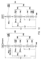
- the sensor incorporated plug 20A and the plugs 20B are connected to four drive circuits DV1 to DV4, respectively, of a glow plug control unit (GCU) through the electricity supply cables 300A and 300B encompassing the electricity supply lines 310A and 310B.
- GCU glow plug control unit
- the GCU is connected to an external power supply BT (battery) mounted in a vehicle. Voltage applied from the external power supply BT is pulse-driven by the drive circuits DV1 to DV4 and is then output from the GCU.
- the housings 100A and 100B of the sensor incorporated plug 20A and the plugs 20B are connected to a reference potential GND through the engine body 10.
- electricity from the external power supply BT is supplied to the heaters 130A and 130B of the sensor incorporated plug 20A and the plugs 20B through the drive circuits DV1 to DV 4 and the electricity supply lines 310A and 310B of the electricity supply cables 300A and 300B.
- a first structure 30A is an overall structure composed of the sensor incorporated plug 20A and the electricity supply cable 300A connected to the sensor incorporated plug 20A
- a second structure 30B is an overall structure composed of the plug 20B and the electricity supply cable 300B connected to the plug 20B.
- the first structure 30A and the second structure 30B correspond to the first section and the second section, respectively, in the present invention.
- the GCU is connected to an electronic control unit (ECU) and controls electricity supply to the glow plugs under instructions from the ECU.
- ECU electronice control unit
- the GCU performs the same control on the four drive circuits DV1 to DV4; specifically, the GCU pulse-drives the drive circuits DV1 to DV4 at the same duty ratio.
- the drive circuits DV1 to DV4 supply electricity, at the same duty ratio (effective applied voltage), to the first structure 30A composed of the sensor incorporated plug 20A mounted to the cylinder 11A and the electricity supply cable 300A connected to the sensor incorporated plug 20A, and to the second structures 30B composed of the plugs 20B mounted to the cylinders 11B to 11D and the electricity supply cables 300B connected to the plugs 20B.
- the sensor incorporated plug 20A, the plugs 20B, and the electricity supply cables 300A and 300B (electricity supply lines 310A and 310B) connected to the plugs 20A and 20B are a plurality of resistances connected in series.
- the drive circuits DV1 to DV4 apply voltage to resistances of the members.
- a first section voltage Vc1 is a voltage which the drive circuit DV1 applies to the first structure 30A (first section) composed of the sensor incorporated plug 20A and the electricity supply cable 300A.
- a second section voltage Vc2 is a voltage which the drive circuit DV2 (DV3, DV4) applies to the second structure 30B (second section) composed of the plug 20B and the electricity supply cable 300B.
- the first voltage Vc1 is a voltage at the output terminal of the drive circuit DV1 connected to the electricity supply line 310A, with respect to the reference potential GND to which the housing 100A of the sensor incorporated plug 20A is connected.
- the second voltage Vc2 is a voltage at the output terminal of the drive circuit DV2 (DV3, DV4) connected to the electricity supply line 310B, with respect to the reference potential GND to which the housing 100B of the plug 20B is connected.
- a first plug voltage Vp1 is a voltage applied to the sensor incorporated plug 20A
- a second plug voltage Vp2 is a voltage applied to the plug 20B.
- the first plug voltage Vp1 is a voltage applied to the external connection terminal 160A with respect to the reference potential GND to which the housing 100A of the sensor incorporated plug 20A is connected.
- the second plug voltage Vp2 is a voltage applied to the pin terminal 160B with respect to the reference potential GND to which the housing 100B of the plug 20B is connected.
- a first residual section voltage Vz1 is a voltage applied to the first residual section 50A which remains after eliminating the first electrically conductive member 40A from the sensor incorporated plug 20A, at the time when the first plug voltage Vp1 is applied to the sensor incorporated plug 20A.
- a second residual section voltage Vz2 is a voltage applied to the second residual section 50B which remains after eliminating the second electrically conductive member 40B from the plug 20B, at the time when the second plug voltage Vp2 is applied to the plug 20B.
- the first residual section voltage Vz1 corresponds to a voltage at the first ring member 141 with respect to the reference potential GND to which the housing 100A of the sensor incorporated plug 20A is connected, at the time when the first plug voltage Vp1 is applied to the external connection terminal 160A.
- the second residual section voltage Vz2 corresponds to a voltage at the ring member 140 with respect to the reference potential GND to which the housing 100B of the plug 20B is connected, at the time when the second plug voltage Vp2 is applied to the pin terminal 160B.
- the first residual section voltage Vz1 and the second residual section voltage Vz2 can be theoretically obtained from the relations between the first and second plug voltages Vp1 and Vp2 and resistances of members measured beforehand and also can be actually measured, for example, by the following method: the housing 100A (100B) is drilled, and voltage of the first ring member 141 (ring member 140) with respect to the reference potential GND is measured through the drilled hole.
- RB1a is resistance of the electricity supply line 310A (first electricity supply line) connected to the sensor incorporated plug 20A.
- RB2a is resistance of the electricity supply line 310B (second electricity supply line) connected to the plug 20B.
- RA1a is resistance of the first electrically conductive member 40A composed of the external connection terminal 160A (first external terminal), the shaft 120A (first shaft), and the first ring member 141 in the sensor incorporated plug 20A.
- RA2a is resistance of the second electrically conductive member 40B composed of the pin terminal 160B (second external terminal), the shaft 120B (second shaft), and the ring member 140 in the plug 20B.
- resistance RA1a of the first electrically conductive member 40A consists of resistance RA1aa of the shaft 120A (first shaft) and total resistance RA1ab of the external connection terminal 160A and the first ring member 141.
- Resistance RA2a of the second electrically conductive member 40B consists of resistance RA2aa of the shaft 120B (second shaft) and total resistance RAab of the pin terminal 160B and the ring member 140.
- the heater 130A (first heater) of the sensor incorporated plug 20A and the heater 130B (second heater) of the plug 20B are ceramic heaters in common, the heater 130A and the heater 130B differ in energization characteristic.
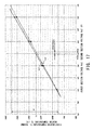
- the sensor incorporated plug 20A and the plug 20B are in such a relation that a first plug voltage Vp1 (see FIG. 6 ) vs. first heater temperature T1 characteristic and a second plug voltage Vp2 (see FIG. 6 ) vs. second heater temperature T2 characteristic are represented by the graph of FIG. 7 , where the first plug voltage Vp1 is applied to the sensor incorporated plug 20A, the second plug voltage Vp2 is applied to the plug 20B, the first heater temperature T1 is the temperature of heat generated by the heater 130A, and the second heater temperature T2 is the temperature of heat generated by the heater 130B.
- the first heater temperature T1 and the second heater temperature T2 in FIG. 7 are measured by use of a radiation thermometer.
- a first plug regression line Lp1 represented by the solid line in FIG. 7 is drawn from a first plug voltage vs. temperature characteristic indicative of the relation, within a temperature range Tr of 950°C to 1,350°C, between the first plug voltage Vp1 applied to the sensor incorporated plug 20A and the first heater temperature T1 indicative of the temperature of heat generated by the heater 130A (first heater).
- a second plug regression line Lp2 represented by the broken line in FIG. 7 is drawn from a second plug voltage vs. temperature characteristic indicative of the relation, within the temperature range Tr, between the second plug voltage Vp2 applied to the plug 20B and the second heater temperature T2 indicative of the temperature of heat generated by the heater 130B (second heater).
- a first voltage Vp1x is the first plug voltage Vp1 which corresponds, on the first plug regression line Lp1, to a predetermined temperature Tx of the first heater temperature T1 within the temperature range Tr.
- a second voltage Vp2x is the second plug voltage Vp2 which corresponds, on the second plug regression line Lp2, to the same predetermined temperature Tx of the second heater temperature T2.
- a first-second plug voltage difference (Vp1x - Vp2x) is the difference at the predetermined temperature Tx between the first voltage Vp1x and the second voltage Vp2x.
- the first plug regression line Lp1 and the second plug regression line Lp2 are in such a relation that, at any predetermined temperature Tx within the temperature range Tr, the second voltage Vp2x is lower than the first voltage Vp1x (Vp2x ⁇ Vp1x).
- the sensor incorporated plug 20A and the plug 20B do not match in a heater energization characteristic indicative of the relation between voltages (first plug voltage Vp1 and second plug voltage Vp2) applied to the plugs and temperatures of heat generated by the heaters (first heater temperature T1 and second heater temperature T2). Also, in the case where the first heater temperature T1 and the second heater temperature T2 are to have the same temperature, a required second plug voltage Vp2 is lower than a required first plug voltage Vp1. In other words, in the case where the first plug voltage Vp1 and the second plug voltage Vp2 applied to the respective glow plugs have the same voltage, the second heater temperature T2 becomes higher than the first heater temperature T1.
- the drive circuits DV1 to DV4 apply electricity to the sensor incorporated plug 20A and the plugs 20B at the same duty ratio (effective applied voltage)
- the first heater temperature T1 and the second heater temperature T2 differ from each other (T2 > T1); as a result, the cylinders are apt to differ in a glow plug action of assisting in start-up.
- resistance RB2a of the electricity supply line 310B (second electricity supply line) connected to the plug 20B is rendered greater than resistance RB1a of the electricity supply line 310A (first electricity supply line) connected to the sensor incorporated plug 20A (RB2a > RB1a).
- the electricity supply line 310A (first electricity supply line) is formed of copper wire
- the electricity supply line 310B (second electricity supply line) is formed of nickel wire, which is higher in specific resistance (electric resistivity) than copper wire.
- the electricity supply line 310B (second electricity supply line) is smaller in cross-sectional area and longer in overall length than the electricity supply line 310A (first electricity supply line).
- the shaft 120A (first shaft) and the shaft 120B (second shaft) are formed of carbon steel. Also, in contrast to the second embodiment, which will be described later, resistance RA1aa of the shaft 120A and resistance RA2aa of the shaft 120B are substantially equal to each other, and resistance RA1a of the first electrically conductive member 40A and resistance RA2a of the second electrically conductive member 40B are substantially equal to each other.
- the first structure 30A (first section) and the second structure 30B (second section) are in such a relation that a first section voltage Vc1 (see FIG. 6 ) vs. first heater temperature T1 characteristic and a second section voltage Vc2 (see FIG. 6 ) vs. second heater temperature T2 characteristic are represented by the graph of FIG. 8 , where the first section voltage Vc1 is applied to the first structure 30A, and the second section voltage Vc2 is applied to the second structure 30B.
- a first section regression line Lc1 represented by the solid line in FIG. 8 is drawn from a first section voltage vs. temperature characteristic indicative of the relation, within a temperature range Tr of 950°C to 1,350°C, between the first section voltage Vc1 applied to the first structure 30A (first section) and the first heater temperature T1 indicative of the temperature of heat generated by the heater 130A (first heater).
- a second section regression line Lc2 represented by the broken line in FIG. 8 is drawn from a second section voltage vs. temperature characteristic indicative of the relation, within the temperature range Tr, between the second section voltage Vc2 applied to the second structure 30B (second section) and the second heater temperature T2 indicative of the temperature of heat generated by the heater 130B (second heater).
- a third voltage Vc1x is the first section voltage Vc1 which corresponds, on the first section regression line Lc1, to the predetermined temperature Tx of the first heater temperature T1 within the temperature range Tr.
- a fourth voltage Vc2x is the second section voltage Vc2 which corresponds, on the second section regression line Lc2, to the same predetermined temperature Tx of the second heater temperature T2.
- is an absolute value of the difference at the predetermined temperature Tx between the third voltage Vc1x and the fourth voltage Vc2x.
- the first section regression line Lc1 and the second section regression line Lc2 are in such a relation that, at any predetermined temperature Tx within the temperature range Tr, the overall voltage deviation
- deviation between the first section voltage Vc1 and the second section voltage Vc2 absolute value of the difference between the two voltages required for the first heater temperature T1 and the second heater temperature T2 to have the same temperature is smaller than the difference between the first plug voltage Vp1 and the second plug voltage Vp2.
- resistance RB2a of the electricity supply line 310B (second electricity supply line) is rendered greater than resistance RB1a of the electricity supply line 310A (first electricity supply line).
- an energization characteristic (the relation between the first section voltage Vc1 and the first heater temperature T1) of the first structure 30A (first section) composed of the sensor incorporated plug 20A and the electricity supply cable 300A (first electricity supply cable)
- an energization characteristic (the relation between the second section voltage Vc2 and the second heater temperature T2) of the second structure 30B (second section) composed of the plug 20B and the electricity supply cable 300B (second electricity supply cable) are closer to each other.
- the internal combustion engine 1 in which, upon application of the same effective voltage from the drive circuits DV1 to DV4 to overall structures consisting of the electricity supply cables 300A and 300B and the glow plugs 20A and 20B, the difference in heater temperature among cylinders is restrained.
- FIGS. 1 and 5 similar to the internal combustion engine 1 of the first embodiment described above, in an internal combustion engine 1A according to the second embodiment, of the four cylinders 11A to 11D of the engine body 10, the cylinder 11A has the sensor incorporated plug 20A mounted thereto, and the remaining three cylinders 11B to 11D each have the plug 20B mounted thereto and having no pressure sensor.
- the sensor incorporated plug 20A and the plugs 20B are connected to the four drive circuits DV1 to DV4, respectively, of the GCU through the electricity supply cables 300A and 300B encompassing the electricity supply lines 310A and 310B.
- the drive circuits DV1 to DV4 supply electricity, at the same duty ratio (effective applied voltage), to the first structure 30A composed of the sensor incorporated plug 20A and the electricity supply cable 300A connected to the sensor incorporated plug 20A, and to the second structures 30B composed of the plugs 20B and the electricity supply cables 300B connected to the plugs 20B.
- RB1b is resistance of the electricity supply line 310A (first electricity supply line) connected to the sensor incorporated plug 20A.
- RB2b is resistance of the electricity supply line 310B (second electricity supply line) connected to the plug 20B.
- RA1b is resistance of the first electrically conductive member 40A composed of the external connection terminal 160A (first external terminal), the shaft 120A (first shaft), and the first ring member 141 in the sensor incorporated plug 20A.
- RA2b is resistance of the second electrically conductive member 40B composed of the pin terminal 160B (second external terminal), the shaft 120B (second shaft), and the ring member 140 in the plug 20B.
- resistance RA1b of the first electrically conductive member 40A consists of resistance RA1ba of the shaft 120A (first shaft) and total resistance RA1bb of the external connection terminal 160A and the first ring member 141.
- Resistance RA2b of the second electrically conductive member 40B consists of resistance RA2ba of the shaft 120B (second shaft) and total resistance RA2bb of the pin terminal 160B and the ring member 140.
- the sensor incorporated plug 20A and the plug 20B are in such a relation that a first residual section voltage Vz1 (see FIG. 9 ) vs. first heater temperature T1 characteristic and a second residual section voltage Vz2 (see FIG. 9 ) vs. second heater temperature T2 characteristic are represented by the graph of FIG. 10 , where the first residual section voltage Vz1 is applied to the first residual section 50A, the second residual section voltage Vz2 is applied to the second residual section 50B, the first heater temperature T1 is the temperature of heat generated by the heater 130A, and the second heater temperature T2 is the temperature of heat generated by the heater 130B.
- the housing 100A (100B) is drilled for experimental use, and electrical potential of the first ring member 141 (ring member 140) with respect to the reference potential GND is measured through the drilled hole.
- the first heater temperature T1 and the second heater temperature T2 are measured by measuring the temperatures of the heaters 130A and 130B by use of a radiation thermometer.
- a first residual section regression line Lz1 represented by the solid line in FIG. 10 is drawn from a first residual section voltage vs. temperature characteristic indicative of the relation, within a temperature range Tr of 950°C to 1,350°C, between the first residual section voltage Vz1 and the first heater temperature T1 indicative of the temperature of heat generated by the heater 130A (first heater).
- a second residual section regression line Lz2 represented by the broken line in FIG. 10 is drawn from a second residual section voltage vs. temperature characteristic indicative of the relation, within the temperature range Tr, between the second residual section voltage Vz2 and the second heater temperature T2 indicative of the temperature of heat generated by the heater 130B (second heater).
- a first voltage Vz1x is the first residual section voltage Vz1 which corresponds, on the first residual section regression line Lz1, to the predetermined temperature Tx of the first heater temperature T1 within the temperature range Tr.
- a second voltage Vz2x is the second residual section voltage Vz2 which corresponds, on the second residual section regression line Lz2, to the same predetermined temperature Tx of the second heater temperature T2.
- a first-second residual section voltage difference (Vz1x - Vz2x) is the difference at the predetermined temperature Tx between the first voltage Vz1x and the second voltage Vz2x.
- the first residual section regression line Lz1 and the second residual section regression line Lz2 are in such a relation that, at any predetermined temperature Tx within the temperature range Tr, the second voltage Vz2x is lower than the first voltage Vz1x (Vz2x ⁇ Vzlx).
- the sensor incorporated plug 20A and the plug 20B do not match in a heater energization characteristic; specifically, in comparison of the first residual section 50A and the second residual section 50B, an energization characteristic of the heater 130A (first heater) (the relation between the first residual section voltage Vz1 and the first heater temperature T1) with respect to the first residual section 50A and an energization characteristic of the heater 130B (second heater) (the relation between the second residual section voltage Vz2 and the second heater temperature T2) with respect to the second residual section 50B do not match.
- first heater the relation between the first residual section voltage Vz1 and the first heater temperature T1
- second heater the relation between the second residual section voltage Vz2 and the second heater temperature T2
- a required second residual section voltage Vz2 is lower than a required first residual section voltage Vz1.
- the second heater temperature T2 becomes higher than the first heater temperature T1.
- the drive circuits DV1 to DV4 apply electricity to the sensor incorporated plug 20A and the plugs 20B at the same duty ratio (effective voltage)
- the first heater temperature T1 and the second heater temperature T2 differ from each other (T2 > T1); as a result, the cylinders are apt to differ in a glow plug action of assisting in start-up.
- resistance RB2b of the electricity supply line 310B (second electricity supply line) rendered greater than resistance RB1b of the electricity supply line 310A (first electricity supply line) (RB2b > RB1b), but also resistance RA2ba of the shaft 120B (second shaft) is rendered greater than resistance RA1ba of the shaft 120A (first shaft) (RA2ba > RAlba). That is, resistance RA2b of the second electrically conductive member 40B is rendered greater than resistance RA1b of the first electrically conductive member 40A (RA2b > RAlb).
- the electricity supply line 310A (first electricity supply line) is formed of copper wire
- the electricity supply line 310B (second electricity supply line) is formed of nickel wire, which is higher in specific resistance (electric resistivity) than copper wire.
- the electricity supply line 310B (second electricity supply line) is smaller in cross-sectional area and longer in overall length than the electricity supply line 310A (first electricity supply line).
- the shaft 120A (first shaft) and the shaft 120B (second shaft) are formed of carbon steel
- the shaft 120A (first shaft) is formed of carbon steel
- the shaft 120B (second shaft) is formed of stainless steel, which is higher in specific resistance (electric resistivity) than carbon steel.
- the first structure 30A (first section) and the second structure 30B (second section) are in such a relation that the first section voltage Vc1 (see FIG. 9 ) vs. first heater temperature T1 characteristic and a second section voltage Vc2 (see FIG. 9 ) vs. second heater temperature T2 characteristic are represented by the graph of FIG. 11 , where the first section voltage Vc1 is applied to the first structure 30A, and the second section voltage Vc2 is applied to the second structure 30B.
- the first section regression line Lc1 represented by the solid line in FIG. 11 is drawn from a first section voltage vs. temperature characteristic indicative of the relation, within a temperature range Tr of 950°C to 1,350°C, between the first section voltage Vc1 applied to the first structure 30A (first section) and the first heater temperature T1 indicative of the temperature of heat generated by the heater 130A (first heater).
- the second section regression line Lc2 represented by the broken line in FIG. 11 is drawn from a second section voltage vs. temperature characteristic indicative of the relation, within the temperature range Tr, between the second section voltage Vc2 applied to the second structure 30B (second section) and the second heater temperature T2 indicative of the temperature of heat generated by the heater 130B (second heater).
- the third voltage Vc1x is the first section voltage Vc1 which corresponds, on the first section regression line Lc1, to the predetermined temperature Tx of the first heater temperature T1 within the temperature range Tr.
- the fourth voltage Vc2x is the second section voltage Vc2 which corresponds, on the second section regression line Lc2, to the same predetermined temperature Tx of the second heater temperature T2.
- is an absolute value of the difference at the predetermined temperature Tx between the third voltage Vc1x and the fourth voltage Vc2x.
- the first section regression line Lc1 and the second section regression line Lc2 are in such a relation that, at any predetermined temperature Tx within the temperature range Tr, the overall voltage deviation
- deviation between the first section voltage Vc1 and the second section voltage Vc2 absolute value of the difference between the two voltages required for the first heater temperature T1 and the second heater temperature T2 to have the same temperature is smaller than the difference between the first residual section voltage Vz1 and the second residual section voltage Vz2.
- an energization characteristic (the relation between the first section voltage Vc1 and the first heater temperature T1) of the first structure 30A (first section) composed of the sensor incorporated plug 20A and the electricity supply cable 300A (first electricity supply cable) and an energization characteristic (the relation between the second section voltage Vc2 and the second heater temperature T2) of the second structure 30B (second section) composed of the plug 20B and the electricity supply cable 300B (second electricity supply cable) are closer to each other.
- the internal combustion engine 1A in which, upon application of the same effective voltage from the drive circuits DV1 to DV4 to overall structures consisting of the electricity supply cables 300A and 300B and the glow plugs 20A and 20B, the difference in heater temperature among cylinders is restrained.
- resistance RB2b of the electricity supply line 310B (second electricity supply line) rendered greater than resistance RB1b of the electricity supply line 310A (first electricity supply line), but also resistance RA2ba of the shaft 120B (second shaft) is rendered greater than resistance RA1ba of the shaft 120A (first shaft).
- the shaft 120A and the shaft 120B are major portions of the first electrically conductive member 40A and the second electrically conductive member 40B, respectively, and have a certain length and a certain diameter, differentiating resistances RA1ba and RA2ba of the first and second shafts 120A and 120B, respectively, is relatively easy.
- resistance RB2b of the electricity supply line 310B (second electricity supply line) rendered greater than resistance RB1b of the electricity supply line 310A (first electricity supply line), but also resistance RA2ba of the shaft 120B (second shaft) is rendered greater than resistance RA1ba of the shaft 120A (first shaft).
- FIGS. 1 and 5 similar to the internal combustion engines 1 and 1A of the first and second embodiments, respectively, described above, in an internal combustion engine 1B according to the third embodiment, of the four cylinders 11A to 11D of the engine body 10, the cylinder 11A has the sensor incorporated plug 20A mounted thereto, and the remaining three cylinders 11B to 11D each have the plug 20B mounted thereto and having no pressure sensor.
- the sensor incorporated plug 20A and the plugs 20B are connected to the four drive circuits DV1 to DV4, respectively, of the GCU through the electricity supply cables 300A and 300B encompassing the electricity supply lines 310A and 310B.
- the drive circuits DV1 to DV4 supply electricity, at the same duty ratio (effective applied voltage), to the first structure 30A composed of the sensor incorporated plug 20A and the electricity supply cable 300A connected to the sensor incorporated plug 20A, and to the second structures 30B composed of the plugs 20B and the electricity supply cables 300B connected to the plugs 20B.
- RB1c is resistance of the electricity supply line 310A (first electricity supply line) connected to the sensor incorporated plug 20A.
- RB2c is resistance of the electricity supply line 310B (second electricity supply line) connected to the plug 20B.
- RA1c is resistance of the first electrically conductive member 40A composed of the external connection terminal 160A (first external terminal), the shaft 120A (first shaft), and the first ring member 141 in the sensor incorporated plug 20A.
- RA2c is resistance of the second electrically conductive member 40B composed of the pin terminal 160B (second external terminal), the shaft 120B (second shaft), and the ring member 140 in the plug 20B.
- resistance RA1c of the first electrically conductive member 40A consists of resistance RA1ca of the shaft 120A (first shaft) and total resistance RA1cb of the external connection terminal 160A and the first ring member 141.
- Resistance RA2c of the second electrically conductive member 40B consists of resistance RA2ca of the shaft 120B (second shaft) and total resistance RA2cb of the pin terminal 160B and the ring member 140.
- the sensor incorporated plug 20A and the plug 20B are in such a relation that a first plug voltage Vp1 (see FIG. 12 ) vs. first heater temperature T1 characteristic and a second plug voltage Vp2 (see FIG. 12 ) vs. second heater temperature T2 characteristic are represented by the graph of FIG. 13 , where the first plug voltage Vp1 is applied to the sensor incorporated plug 20A, the second plug voltage Vp2 is applied to the plug 20B, the first heater temperature T1 is the temperature of heat generated by the heater 130A, and the second heater temperature T2 is the temperature of heat generated by the heater 130B.
- the first plug regression line Lp1 represented by the solid line in FIG. 13 is drawn from a first plug voltage vs. temperature characteristic indicative of the relation, within a temperature range Tr of 950°C to 1,350°C, between the first plug voltage Vp1 applied to the sensor incorporated plug 20A and the first heater temperature T1 indicative of the temperature of heat generated by the heater 130A (first heater).
- the second plug regression line Lp2 represented by the broken line in FIG. 13 is drawn from a second plug voltage vs. temperature characteristic indicative of the relation, within the temperature range Tr, between the second plug voltage Vp2 applied to the plug 20B and the second heater temperature T2 indicative of the temperature of heat generated by the heater 130B (second heater).
- the first voltage Vp1x is the first plug voltage Vp1 which corresponds, on the first plug regression line Lp1, to the predetermined temperature Tx of the first heater temperature T1 within the temperature range Tr.
- the second voltage Vp2x is the second plug voltage Vp2 which corresponds, on the second plug regression line Lp2, to the same predetermined temperature Tx of the second heater temperature T2.
- a second-first plug voltage difference (Vp2x - Vp1x) is the difference at the predetermined temperature Tx between the second voltage Vp2x and the first voltage Vp1x.
- the first plug regression line Lp1 and the second plug regression line Lp2 are in such a relation that, at any predetermined temperature Tx within the temperature range Tr, the second voltage Vp2x is higher than the first voltage Vp1x (Vp2x > Vp1x).
- the sensor incorporated plug 20A and the plug 20B do not match in a heater energization characteristic indicative of the relation between voltages (first plug voltage Vp1 and second plug voltage Vp2) applied to the plugs and temperatures of heat generated by the heaters (first heater temperature T1 and second heater temperature T2). Also, in the case where the first heater temperature T1 and the second heater temperature T2 are to have the same temperature, a required second plug voltage Vp2 is higher than a required first plug voltage Vp1. In other words, in the case where the first plug voltage Vp1 and the second plug voltage Vp2 applied to the respective glow plugs have the same voltage, the second heater temperature T2 becomes lower than the first heater temperature T1.
- the drive circuits DV1 to DV4 apply electricity to the sensor incorporated plug 20A and the plugs 20B at the same duty ratio (effective voltage)
- the first heater temperature T1 and the second heater temperature T2 differ from each other (T2 ⁇ T1); as a result, the cylinders are apt to differ in a glow plug action of assisting in start-up.
- resistance RB2c of the electricity supply line 310B (second electricity supply line) connected to the plug 20B is rendered smaller than resistance RB1c of the electricity supply line 310A (first electricity supply line) connected to the sensor incorporated plug 20A (RB2c ⁇ RB1c).
- the electricity supply line 310B (second electricity supply line) is formed of copper wire
- the electricity supply line 310A (first electricity supply line) is formed of nickel wire, which is higher in specific resistance (electric resistivity) than copper wire.
- the electricity supply line 310A (first electricity supply line) is smaller in cross-sectional area and longer in overall length than the electricity supply line 310B (second electricity supply line).
- the shaft 120A (first shaft) and the shaft 120B (second shaft) are formed of carbon steel. Also, in contrast to the fourth embodiment, which will be described later, resistance RA1ca of the shaft 120A and resistance RA2ca of the shaft 120B are substantially equal to each other, and resistance RA1c of the first electrically conductive member 40A and resistance RA2c of the second electrically conductive member 40B are substantially equal to each other.
- the first structure 30A (first section) and the second structure 30B (second section) are in such a relation that a first section voltage Vc1 (see FIG. 12 ) vs. first heater temperature T1 characteristic and a second section voltage Vc2 (see FIG. 12 ) vs. second heater temperature T2 characteristic are represented by the graph of FIG. 14 , where the first section voltage Vc1 is applied to the first structure 30A, and the second section voltage Vc2 is applied to the second structure 30B.
- the first section regression line Lc1 represented by the solid line in FIG. 14 is drawn from a first section voltage vs. temperature characteristic indicative of the relation, within a temperature range Tr of 950°C to 1,350°C, between the first section voltage Vc1 applied to the first structure 30A (first section) and the first heater temperature T1 indicative of the temperature of heat generated by the heater 130A (first heater).
- the second section regression line Lc2 represented by the broken line in FIG. 14 is drawn from a second section voltage vs. temperature characteristic indicative of the relation, within the temperature range Tr, between the second section voltage Vc2 applied to the second structure 30B (second section) and the second heater temperature T2 indicative of the temperature of heat generated by the heater 130B (second heater).
- the third voltage Vc1x is the first section voltage Vc1 which corresponds, on the first section regression line Lc1, to the predetermined temperature Tx of the first heater temperature T1 within the temperature range Tr.
- the fourth voltage Vc2x is the second section voltage Vc2 which corresponds, on the second section regression line Lc2, to the same predetermined temperature Tx of the second heater temperature T2.
- is an absolute value of the difference at the predetermined temperature Tx between the fourth voltage Vc2x and the third voltage Vc1x.
- the first section regression line Lc1 and the second section regression line Lc2 are in such a relation that, at any predetermined temperature Tx within the temperature range Tr, the overall voltage deviation lVc2x - Vc1x
- deviation between the second section voltage Vc2 and the first section voltage Vc1 absolute value of the difference between the two voltages required for the first heater temperature T1 and the second heater temperature T2 to have the same temperature is smaller than the difference between the second plug voltage Vp2 and the first plug voltage Vp1.
- resistance RB2c of the electricity supply line 310B (second electricity supply line) is rendered smaller than resistance RB1c of the electricity supply line 310A (first electricity supply line).
- an energization characteristic (the relation between the first section voltage Vc1 and the first heater temperature T1) of the first structure 30A (first section) composed of the sensor incorporated plug 20A and the electricity supply cable 300A (first electricity supply cable)
- an energization characteristic (the relation between the second section voltage Vc2 and the second heater temperature T2) of the second structure 30B (second section) composed of the plug 20B and the electricity supply cable 300B (second electricity supply cable) are closer to each other.
- the internal combustion engine 1B in which, upon application of the same effective voltage from the drive circuits DV1 to DV4 to overall structures consisting of the electricity supply cables 300A and 300B and the glow plugs 20A and 20B, the difference in heater temperature among cylinders is restrained.
- FIGS. 1 and 5 similar to the internal combustion engines 1, 1A, and 1B of the first to third embodiments described above, in an internal combustion engine 1C according to the fourth embodiment, of the four cylinders 11A to 11D of the engine body 10, the cylinder 11A has the sensor incorporated plug 20A mounted thereto, and the remaining three cylinders 11B to 11D each have the plug 20B mounted thereto and having no pressure sensor.
- the sensor incorporated plug 20A and the plugs 20B are connected to the four drive circuits DV1 to DV4, respectively, of the GCU through the electricity supply cables 300A and 300B encompassing the electricity supply lines 310A and 310B.
- the drive circuits DV1 to DV4 supply electricity, at the same duty ratio (effective applied voltage), to the first structure 30A composed of the sensor incorporated plug 20A and the electricity supply cable 300A connected to the sensor incorporated plug 20A, and to the second structures 30B composed of the plugs 20B and the electricity supply cables 300B connected to the plugs 20B.
- RB1d is resistance of the electricity supply line 310A (first electricity supply line) connected to the sensor incorporated plug 20A.
- RB2d is resistance of the electricity supply line 310B (second electricity supply line) connected to the plug 20B.
- RAld is resistance of the first electrically conductive member 40A composed of the external connection terminal 160A (first external terminal), the shaft 120A (first shaft), and the first ring member 141 in the sensor incorporated plug 20A.
- RA2d is resistance of the second electrically conductive member 40B composed of the pin terminal 160B (second external terminal), the shaft 120B (second shaft), and the ring member 140 in the plug 20B.
- resistance RAld of the first electrically conductive member 40A consists of resistance RA1da of the shaft 120A (first shaft) and total resistance RA1db of the external connection terminal 160A and the first ring member 141.
- Resistance RA2d of the second electrically conductive member 40B consists of resistance RA2da of the shaft 120B (second shaft) and total resistance RA2db of the pin terminal 160B and the ring member 140.
- the sensor incorporated plug 20A and the plug 20B are in such a relation that a first residual section voltage Vz1 (see FIG. 15 ) vs. first heater temperature T1 characteristic and a second residual section voltage Vz2 (see FIG. 15 ) vs. second heater temperature T2 characteristic are represented by the graph of FIG. 16 , where the first residual section voltage Vz1 is applied to the first residual section 50A, the second residual section voltage Vz2 is applied to the second residual section 50B, the first heater temperature T1 is the temperature of heat generated by the heater 130A, and the second heater temperature T2 is the temperature of heat generated by the heater 130B.
- the first residual section voltage Vz1 and the second residual section voltage Vz2 in FIG. 16 are measured by the following method: the housing 100A (100B) is drilled for experimental use, and electrical potential of the first ring member 141 (ring member 140) with respect to the reference potential GND is measured through the drilled hole.
- the first residual section regression line Lz1 represented by the solid line in FIG. 16 is drawn from a first residual section voltage vs. temperature characteristic indicative of the relation, within a temperature range Tr of 950°C to 1,350°C, between the first residual section voltage Vz1 and the first heater temperature T1 indicative of the temperature of heat generated by the heater 130A (first heater).
- the second residual section regression line Lz2 represented by the broken line in FIG. 16 is drawn from a second residual section voltage vs. temperature characteristic indicative of the relation, within the temperature range Tr, between the second residual section voltage Vz2 and the second heater temperature T2 indicative of the temperature of heat generated by the heater 130B (second heater).
- the first voltage Vz1x is the first residual section voltage Vz1 which corresponds, on the first residual section regression line Lz1, to the predetermined temperature Tx of the first heater temperature T1 within the temperature range Tr.
- the second voltage Vz2x is the second residual section voltage Vz2 which corresponds, on the second residual section regression line Lz2, to the same predetermined temperature Tx of the second heater temperature T2.
- a second-first residual section voltage difference (Vz2x - Vz1x) is the difference at the predetermined temperature Tx between the second voltage Vz2x and the first voltage Vz1x.
- the first residual section regression line Lz1 and the second residual section regression line Lz2 are in such a relation that, at any predetermined temperature Tx within the temperature range Tr, the second voltage Vz2x is higher than the first voltage Vz1x (Vz2x > Vzlx).
- the sensor incorporated plug 20A and the plug 20B do not match in a heater energization characteristic; specifically, in comparison of the first residual section 50A and the second residual section 50B, an energization characteristic of the heater 130A (first heater) (the relation between the first residual section voltage Vz1 and the first heater temperature T1) with respect to the first residual section 50A and an energization characteristic of the heater 130B (second heater) (the relation between the second residual section voltage Vz2 and the second heater temperature T2) with respect to the second residual section 50B do not match.
- first heater the relation between the first residual section voltage Vz1 and the first heater temperature T1
- second heater the relation between the second residual section voltage Vz2 and the second heater temperature T2
- a required second residual section voltage Vz2 is higher than a required first residual section voltage Vz1.
- the second heater temperature T2 becomes lower than the first heater temperature T1.
- the drive circuits DV1 to DV4 apply electricity to the sensor incorporated plug 20A and the plugs 20B at the same duty ratio (effective voltage)
- the first heater temperature T1 and the second heater temperature T2 differ from each other (T2 ⁇ T1); as a result, the cylinders are apt to differ in a glow plug action of assisting in start-up.
- resistance RB2d of the electricity supply line 310B (second electricity supply line) rendered smaller than resistance RB1d of the electricity supply line 310A (first electricity supply line) (RB2d ⁇ RB1d), but also resistance RA2da of the shaft 120B (second shaft) is rendered smaller than resistance RA1da of the shaft 120A (first shaft) (RA2da ⁇ RAlda). That is, resistance RA2d of the second electrically conductive member 40B is rendered smaller than resistance RAld of the first electrically conductive member 40A (RA2d ⁇ RA1d).
- the electricity supply line 310B (second electricity supply line) is formed of copper wire, whereas, similar to the case of the third embodiment, the electricity supply line 310A (first electricity supply line) is formed of nickel wire, which is higher in specific resistance (electric resistivity) than copper wire. Furthermore, the electricity supply line 310A (first electricity supply line) is smaller in cross-sectional area and longer in overall length than the electricity supply line 310B (second electricity supply line).
- the shaft 120B (second shaft) is formed of carbon steel
- the shaft 120A (first shaft) is formed of stainless steel, which is higher in specific resistance (electric resistivity) than carbon steel.
- the first structure 30A (first section) and the second structure 30B (second section) are in such a relation that the first section voltage Vc1 (see FIG. 15 ) vs. first heater temperature T1 characteristic and a second section voltage Vc2 (see FIG. 15 ) vs. second heater temperature T2 characteristic are represented by the graph of FIG. 17 , where the first section voltage Vc1 is applied to the first structure 30A, and the second section voltage Vc2 is applied to the second structure 30B.
- the first section regression line Lc1 represented by the solid line in FIG. 17 is drawn from a first section voltage vs. temperature characteristic indicative of the relation, within a temperature range Tr of 950°C to 1,350°C, between the first section voltage Vc1 applied to the first structure 30A (first section) and the first heater temperature T1 indicative of the temperature of heat generated by the heater 130A (first heater).
- the second section regression line Lc2 represented by the broken line in FIG. 17 is drawn from a second section voltage vs. temperature characteristic indicative of the relation, within the temperature range Tr, between the second section voltage Vc2 applied to the second structure 30B (second section) and the second heater temperature T2 indicative of the temperature of heat generated by the heater 130B (second heater).
- the third voltage Vc1x is the first section voltage Vc1 which corresponds, on the first section regression line Lc1, to the predetermined temperature Tx of the first heater temperature T1 within the temperature range Tr.
- the fourth voltage Vc2x is the second section voltage Vc2 which corresponds, on the second section regression line Lc2, to the same predetermined temperature Tx of the second heater temperature T2.
- is an absolute value of the difference at the predetermined temperature Tx between the fourth voltage Vc2x and the third voltage Vc1x.
- the first section regression line Lc1 and the second section regression line Lc2 are in such a relation that, at any predetermined temperature Tx within the temperature range Tr, the overall voltage deviation
- deviation between the second section voltage Vc2 and the first section voltage Vc1 absolute value of the difference between the two voltages required for the first heater temperature T1 and the second heater temperature T2 to have the same temperature is smaller than the difference between the second residual section voltage Vz2 and the first residual section voltage Vz1.
- an energization characteristic (the relation between the first section voltage Vc1 and the first heater temperature T1) of the first structure 30A (first section) composed of the sensor incorporated plug 20A and the electricity supply cable 300A (first electricity supply cable) and an energization characteristic (the relation between the second section voltage Vc2 and the second heater temperature T2) of the second structure 30B (second section) composed of the plug 20B and the electricity supply cable 300B (second electricity supply cable) are closer to each other.
- the internal combustion engine 1C in which, upon application of the same effective voltage from the drive circuits DV1 to DV4 to overall structures consisting of the electricity supply cables 300A and 300B and the glow plugs 20A and 20B, the difference in heater temperature among cylinders is restrained.
- the internal combustion engine 1C of the present fourth embodiment by means of not only rendering resistance RB2d of the electricity supply line 310B (second electricity supply line) smaller than resistance RB1d of the electricity supply line 310A (first electricity supply line), but also rendering resistance RA2d of the second electrically conductive member 40B smaller than resistance RAld of the first electrically conductive member 40A, energization characteristics of the heaters 130A and 130B with respect to overall structures composed of the cables 300A and 300B and the glow plugs 20A and 20B can be brought close to each other.
- resistance RB2d of the electricity supply line 310B (second electricity supply line) rendered smaller than resistance RB1d of the electricity supply line 310A (first electricity supply line), but also resistance RA2da of the shaft 120B (second shaft) is rendered smaller than resistance RA1da of the shaft 120A (first shaft).
- the shaft 120A and the shaft 120B are major portions of the first electrically conductive member 40A and the second electrically conductive member 40B, respectively, and have a certain length and a certain diameter, differentiating resistances RA1da and RA2da of the first and second shafts 120A and 120B, respectively, is relatively easy.
- resistance RB2d of the electricity supply line 310B (second electricity supply line) is rendered smaller than resistance RB1d of the electricity supply line 310A (first electricity supply line), but also resistance RA2da of the shaft 120B (second shaft) is rendered smaller than resistance RA1da of the shaft 120A (first shaft).
- the configuration of the present fourth embodiment becomes similar to that of the third embodiment shown in FIG. 12 .
- the sensor incorporated plug 20A and the plugs 20B are so-called ceramic glow plugs having ceramic heaters as the heater 130A (first heater) and the heater 130B (second heater), respectively.
- the combustion pressure sensor incorporated glow plug and the sensor nonincorporated glow plug are not limited thereto.
- a so-called metal glow plug having a sheath heater may be employed.
- the regression lines are drawn from voltage vs. temperature characteristics within a temperature range Tr of 950°C to 1,350°C.
- the metal glow plug is used with a highest temperature of the heater lower than that of the ceramic glow plug.
- the regression lines may be drawn from voltage vs. temperature characteristics in a temperature range of, for example, 950°C to 1,100°C instead of a temperature range of 950°C to 1,350°C.
- the first to fourth embodiments are described while mentioning the internal combustion engines 1, 1A, 1B, and 1C in which, of the four cylinders 11A to 11D of the engine body 10, the cylinder 11A is mounted with the sensor incorporated plug 20A, and the remaining three cylinders 11B to 11D are mounted with the respective plugs 20B having no pressure sensor.
- the present invention may be applied to an internal combustion engine in which the number of cylinders, the number of the combustion pressure sensor incorporated glow plugs, and the number of the sensor nonincorporated glow plugs differ from those of the embodiments; for example, of six cylinders of a 6-cylinder engine, two cylinders are mounted with respective combustion pressure sensor incorporated glow plugs, and the remaining four cylinders are mounted with the respective sensor nonincorporated glow plugs.
Landscapes
- Engineering & Computer Science (AREA)
- Chemical & Material Sciences (AREA)
- Combustion & Propulsion (AREA)
- Physics & Mathematics (AREA)
- General Physics & Mathematics (AREA)
- Mechanical Engineering (AREA)
- General Engineering & Computer Science (AREA)
- Combined Controls Of Internal Combustion Engines (AREA)
- Control Of Vehicle Engines Or Engines For Specific Uses (AREA)
- Measuring Fluid Pressure (AREA)
Abstract
Description
- The present invention relates to an internal combustion engine in which a combustion pressure sensor incorporated glow plug is mounted to one or more of a plurality of cylinders of an engine body, and a sensor nonincorporated glow plug having no pressure sensor is mounted to each of the remaining cylinders.
- A known combustion pressure sensor incorporated glow plug is a glow plug which assists in start-up of an internal combustion engine such as a diesel engine and into which a pressure sensor is incorporated for detecting combustion pressure in a combustion chamber of the internal combustion engine (refer to, for example, Patent Document 1). In the combustion pressure sensor incorporated glow plug, a heater is disposed within a housing in an axially movable condition. An axial movement of the heater resulting from variation in combustion pressure is transmitted to a pressure sensor, thereby detecting combustion pressure within the combustion chamber of the internal combustion engine.
- The internal combustion engine (engine body) has a plurality of cylinders, such as four or six cylinders. In view of costs, etc., such a combustion pressure sensor incorporated glow plug may be used in the internal combustion engine such that the combustion pressure sensor incorporated glow plug is mounted to one or more of a plurality of cylinders, whereas an ordinary glow plug (hereinafter, may be called a sensor nonincorporated glow plug) having no pressure sensor (combustion pressure sensor) is mounted to each of the remaining cylinders.
- [Patent Document 1] Japanese Patent Application Laid-Open (kokai) No.
2012-177483 - However, according to certain control of heaters of glow plugs of cylinders by the ECU (electronic control unit) of a vehicle, the same control is conducted on the cylinders regardless of existence of the combustion pressure sensor such that the heaters are pulse-energized at the same duty ratio without individually controlling the cylinders according to whether or not the combustion pressure incorporated glow plug is provided. Meanwhile, because of a difference in structure, the combustion pressure sensor incorporated glow plug and the sensor nonincorporated glow plug differ in a heater energization characteristic. Specifically, even when the same voltage is applied to the glow plugs, the respective heaters generate heat of different temperatures. Thus, when the ECU applies electricity to the two types of glow plugs; i.e., the sensor incorporated and nonincorporated glow plugs, at the same duty ratio (effective applied voltage), the sensor incorporated and nonincorporated glow plugs may differ in heater temperature; as a result, the cylinders are apt to differ in a glow plug action of assisting in start-up.
- The present invention has been conceived in view of the above problem, and an object of the present invention is to provide an internal combustion engine in which a combustion pressure sensor incorporated glow plug is mounted to one or more of a plurality of cylinders of an engine body, whereas a sensor nonincorporated glow plug having no pressure sensor is mounted to each of the remaining cylinders and in which, when the same effective voltage is applied to overall structures each comprising of a cable and a glow plug, the occurrence of a difference in heater temperature among the cylinders is restrained.
- A mode of the present invention provides an internal combustion engine comprising an engine body having a plurality of cylinders; a combustion pressure sensor incorporated glow plug mounted to one or more of the plurality of cylinders and having a first heater which generates heat through energization, and a pressure sensor for detecting combustion pressure of the cylinder(s) to which the combustion pressure sensor incorporated glow plug is mounted; a first electricity supply cable including a first electricity supply line for supplying electricity from an external power supply to the first heater of the combustion pressure sensor incorporated glow plug; a sensor nonincorporated glow plug mounted to each of the remaining cylinders to which the combustion pressure sensor incorporated glow plug is not mounted, and having a second heater which generates heat through energization and no pressure sensor; and a second electricity supply cable including a second electricity supply line for supplying electricity from the external power supply to the second heater of the sensor nonincorporated glow plug. Assuming that a first plug regression line is drawn from a first plug voltage vs. temperature characteristic indicative of a relation, within a temperature range of 950°C to 1,350°C, between a first plug voltage applied to the combustion pressure sensor incorporated glow plug and a first heater temperature indicative of a temperature of heat generated by the first heater, a second plug regression line is drawn from a second plug voltage vs. temperature characteristic indicative of a relation, within the temperature range, between a second plug voltage applied to the sensor nonincorporated glow plug and a second heater temperature indicative of a temperature of heat generated by the second heater, a first voltage is the first plug voltage at which the first heater temperature becomes a predetermined temperature within the temperature range on the first plug regression line, a second voltage is the second plug voltage at which the second heater temperature becomes the same predetermined temperature on the second plug regression line, and a first-second plug voltage difference is a difference at the predetermined temperature between the first voltage and the second voltage, the first plug regression line and the second plug regression line are in such a relation that, at any predetermined temperature within the temperature range, the second voltage is lower than the first voltage. Resistance of the second electricity supply line is greater than resistance of the first electricity supply line. Assuming that a first section regression line is drawn from a first section voltage vs. temperature characteristic indicative of a relation, within the temperature range, between a first section voltage applied to a first section comprising the combustion pressure sensor incorporated glow plug and the first electricity supply cable, and the first heater temperature, a second section regression line is drawn from a second section voltage vs. temperature characteristic indicative of a relation, within the temperature range, between a second section voltage applied to a second section comprising the sensor nonincorporated glow plug and the second electricity supply cable, and the second heater temperature, a third voltage is the first section voltage at which the first heater temperature becomes the predetermined temperature on the first section regression line, a fourth voltage is the second section voltage at which the second heater temperature becomes the same predetermined temperature on the second section regression line, and an overall voltage deviation is an absolute value of a difference at the predetermined temperature between the third voltage and the fourth voltage, the first section regression line and the second section regression line are in such a relation that, at any predetermined temperature within the temperature range, the overall voltage deviation is smaller than the first-second plug voltage difference.
- In this internal combustion engine, regarding the combustion pressure sensor incorporated glow plug and the sensor nonincorporated glow plug, the first plug regression line and the second plug regression line are in such a relation that, at any heater temperature within a temperature range of 950°C to 1,350°C, the second voltage is lower than the first voltage.
- That is, the combustion pressure sensor incorporated glow plug and the sensor nonincorporated glow plug do not match in a heater energization characteristic indicative of the relation between voltages (first plug voltage and second plug voltage) applied to the glow plugs and temperatures of heat generated by the heaters (first heater temperature and second heater temperature). Also, in the case where the first heater temperature and the second heater temperature are to have the same temperature, a required second plug voltage is lower than a required first plug voltage. In other words, in the case where the first plug voltage and the second plug voltage applied to the respective glow plugs have the same voltage, the second heater temperature becomes higher than the first heater temperature.
- Thus, in this internal combustion engine, resistance of the second electricity supply line of the second electricity supply cable is rendered greater than resistance of the first electricity supply line of the first electricity supply cable. Accordingly, at any heater temperature within the aforementioned temperature range, the first section regression line and the second section regression line are in such a relation that the overall voltage deviation is smaller than the first-second plug voltage difference. That is, deviation between the first section voltage and the second section voltage (absolute value of the difference between the two voltages) required for the first heater temperature and the second heater temperature to have the same temperature is smaller than the difference between the first plug voltage and the second plug voltage.
- As mentioned above, in this internal combustion engine, resistance of the second electricity supply line is rendered greater than resistance of the first electricity supply line. By virtue of this, as compared with the relation between energization characteristics of the heaters with respect to the glow plugs, an energization characteristic (the relation between the first section voltage and the first heater temperature) of the first section (the combustion pressure sensor incorporated glow plug and the first electricity supply cable) and an energization characteristic (the relation between the second section voltage and the second heater temperature) of the second section (the sensor nonincorporated glow plug and the second electricity supply cable) are closer to each other. Thus, there can be yielded an internal combustion engine in which, upon application of the same effective voltage to overall structures each comprising a cable and a glow plug, the difference in heater temperature among cylinders is restrained.
- A method of rendering resistance of the second electricity supply line greater than resistance of the first electricity supply line is to form the second electricity supply line from a material having specific resistance (electric resistivity, Ω·m) higher than that of a material used to form the first electricity supply line. Other methods are to render the cross-sectional area of the second electricity supply line smaller than that of the first electricity supply line and to render the overall length of the second electricity supply line longer than that of the first electricity supply line. Particularly, since changing length is easy for the first electricity supply line (first electricity supply cable) and the second electricity supply line (second electricity supply cable), by means of rendering the overall length of the second electricity supply line longer than that of the first electricity supply line, resistance of the second electricity supply line can be easily rendered greater than resistance of the first electricity supply line.
- Another mode of the present invention provides an internal combustion engine comprising an engine body having a plurality of cylinders; a combustion pressure sensor incorporated glow plug mounted to one or more of the plurality of cylinders and having a first heater which generates heat through energization, and a pressure sensor for detecting combustion pressure of the cylinder(s) to which the combustion pressure sensor incorporated glow plug is mounted; a first electricity supply cable including a first electricity supply line for supplying electricity from an external power supply to the first heater of the combustion pressure sensor incorporated glow plug; a sensor nonincorporated glow plug mounted to each of the remaining cylinders to which the combustion pressure sensor incorporated glow plug is not mounted, and having a second heater which generates heat through energization and no pressure sensor; and a second electricity supply cable including a second electricity supply line for supplying electricity from the external power supply to the second heater of the sensor nonincorporated glow plug. The combustion pressure sensor incorporated glow plug has a first electrically conductive member connected to the first electricity supply line to electrically connect the first electricity supply line to the first heater. The sensor nonincorporated glow plug has a second electrically conductive member connected to the second electricity supply line to electrically connect the second electricity supply line to the second heater. Assuming that a first residual section regression line is drawn from a first residual section voltage vs. temperature characteristic indicative of a relation, within a temperature range of 950°C to 1,350°C, between a first residual section voltage applied to a first residual section encompassing the first heater and remaining after eliminating the first electrically conductive member from the combustion pressure sensor incorporated glow plug, and a first heater temperature indicative of a temperature of heat generated by the first heater, a second residual section regression line is drawn from a second residual section voltage vs. temperature characteristic indicative of a relation, within the temperature range, between a second residual section voltage applied to a second residual section encompassing the second heater and remaining after eliminating the second electrically conductive member from the sensor nonincorporated glow plug, and a second heater temperature indicative of a temperature of heat generated by the second heater, a first voltage is the first residual section voltage at which the first heater temperature becomes a predetermined temperature within the temperature range on the first residual section regression line, a second voltage is the second residual section voltage at which the second heater temperature becomes the same predetermined temperature on the second residual section regression line, and a first-second residual section voltage difference is a difference at the predetermined temperature between the first voltage and the second voltage, the first residual section regression line and the second residual section regression line are in such a relation that, at any predetermined temperature within the temperature range, the second voltage is lower than the first voltage. A sum of resistance of the second electrically conductive member and resistance of the second electricity supply line is greater than a sum of resistance of the first electrically conductive member and resistance of the first electricity supply line. Assuming that a first section regression line is drawn from a first section voltage vs. temperature characteristic indicative of a relation, within the temperature range, between a first section voltage applied to a first section comprising the combustion pressure sensor incorporated glow plug and the first electricity supply cable, and the first heater temperature, a second section regression line is drawn from a second section voltage vs. temperature characteristic indicative of a relation, within the temperature range, between a second section voltage applied to a second section comprising the sensor nonincorporated glow plug and the second electricity supply cable, and the second heater temperature, a third voltage is the first section voltage at which the first heater temperature becomes the predetermined temperature on the first section regression line, a fourth voltage is the second section voltage at which the second heater temperature becomes the same predetermined temperature on the second section regression line, and an overall voltage deviation is an absolute value of a difference at the predetermined temperature between the third voltage and the fourth voltage, the first section regression line and the second section regression line are in such a relation that, at any predetermined temperature within the temperature range, the overall voltage deviation is smaller than the first-second residual section voltage difference.
- In this internal combustion engine, regarding the combustion pressure sensor incorporated glow plug and the sensor nonincorporated glow plug, the first residual section regression line and the second residual section regression line are in such a relation that, at any heater temperature within a temperature range of 950°C to 1,350°C, the second voltage is lower than the first voltage.
- That is, the combustion pressure sensor incorporated glow plug and the sensor nonincorporated glow plug do not match in a heater energization characteristic; specifically, in comparison of the first residual section encompassing the first heater and the second residual section encompassing the second heater, an energization characteristic of the first heater (the relation between the first residual section voltage and the first heater temperature) with respect to the first residual section and an energization characteristic of the second heater (the relation between the second residual section voltage and the second heater temperature) with respect to the second residual section do not match. Also, in the case where the first heater temperature and the second heater temperature are to have the same temperature, a required second residual section voltage is lower than a required first residual section voltage. In other words, in the case where the first residual section voltage and the second residual section voltage have the same voltage, the second heater temperature becomes higher than the first heater temperature.
- Thus, in this internal combustion engine, the sum of resistance of the second electrically conductive member and resistance of the second electricity supply line is rendered greater than the sum of resistance of the first electrically conductive member and resistance of the first electricity supply line. Accordingly, at any heater temperature within the aforementioned temperature range, the first section regression line and the second section regression line are in such a relation that the overall voltage deviation is smaller than the first-second residual section voltage difference. That is, deviation between the first section voltage and the second section voltage (absolute value of the difference between the two voltages) required for the first heater temperature and the second heater temperature to have the same temperature is smaller than the difference between the first residual section voltage and the second residual section voltage.
- As mentioned above, in this internal combustion engine, the sum of resistance of the second electrically conductive member and resistance of the second electricity supply line is rendered greater than the sum of resistance of the first electrically conductive member and resistance of the first electricity supply line. By virtue of this, as compared with the relation between energization characteristics of the heaters with respect to the first residual section and the second residual section, an energization characteristic (the relation between the first section voltage and the first heater temperature) of the first section (the combustion pressure sensor incorporated glow plug and the first electricity supply cable) and an energization characteristic (the relation between the second section voltage and the second heater temperature) of the second section (the sensor nonincorporated glow plug and the second electricity supply cable) are closer to each other. Thus, there can be yielded an internal combustion engine in which, upon application of the same effective voltage to overall structures each comprising a cable and a glow plug, the difference in heater temperature among cylinders is restrained.
- Additionally, in this internal combustion engine, by means of not only rendering resistance of the second electricity supply line greater than resistance of the first electricity supply line, but also rendering resistance of the second electrically conductive member greater than resistance of the first electrically conductive member, energization characteristics of the heaters with respect to overall structures each comprising a cable and a glow plug can be brought close to each other.
- A method of rendering the sum of resistance of the second electrically conductive member and resistance of the second electricity supply line greater than the sum of resistance of the first electrically conductive member and resistance of the first electricity supply line is not only to form the second electricity supply line from a material having specific resistance (electric resistivity) higher than that of a material used to form the first electricity supply line, but also to form the second electrically conductive member from a material having specific resistance (electric resistivity) higher than that of a material used to form the first electrically conductive member.
- A further method is to reduce the cross-sectional areas or to increase the overall lengths of the second electricity supply line and the second electrically conductive member for rendering the second electricity supply line and the second electrically conductive member greater in resistance than the first electricity supply line and the first electrically conductive member.
- Since changing length is easy for the first electricity supply line (first electricity supply cable) and the second electricity supply line (second electricity supply cable), by means of rendering the overall length of the second electricity supply line longer than that of the first electricity supply line, resistance of the second electricity supply line can be easily rendered greater than resistance of the first electricity supply line.
- Preferably, in the above-mentioned internal combustion engine, the combustion pressure sensor incorporated glow plug has a tubular first housing which accommodates the first heater in such a manner that a forward end portion of the first heater protrudes from a forward end of the first housing; the first electrically conductive member includes a first external terminal disposed at a rear side and connected to the first electricity supply line and a rodlike first shaft inserted in the first housing and electrically connecting the first heater and the first external terminal; the sensor nonincorporated glow plug has a tubular second housing which accommodates the second heater in such a manner that a forward end portion of the second heater protrudes from a forward end of the second housing; the second electrically conductive member includes a second external terminal disposed at a rear side and connected to the second electricity supply line and a rodlike second shaft inserted in the second housing and electrically connecting the second heater and the second external terminal; and at least one of the following conditions is employed: resistance of the second shaft is greater than resistance of the first shaft, and resistance of the second electricity supply line is greater than resistance of the first electricity supply line.
- In this internal combustion engine, in order to render the sum of resistance of the second electrically conductive member and resistance of the second electricity supply line greater than the sum of resistance of the first electrically conductive member and resistance of the first electricity supply line, at least one of the following conditions is employed: resistance of a second shaft is greater than resistance of a first shaft, and resistance of the second electricity supply line is greater than resistance of the first electricity supply line. That is, one of the following three conditions is employed: resistance of the second electricity supply line is greater than resistance of the first electricity supply line; resistance of the second shaft is greater than resistance of the first shaft; and resistance of the second electricity supply line is greater than resistance of the first electricity supply line, and resistance of the second shaft is greater than resistance of the first shaft.
- Since the first shaft and the second shaft are major portions of the first electrically conductive member and the second electrically conductive member, respectively, and have a certain length and a certain diameter, differentiating resistances of the first and second shafts is relatively easy. Thus, by means of rendering resistance of the second electricity supply line greater than resistance of the first electricity supply line, or, in place of or in addition to this, rendering resistance of the second shaft greater than resistance of the first shaft, heater energization characteristics of overall structures each comprising a cable and a glow plug can be brought close to each other.
- A further mode of the present invention provides an internal combustion engine comprising an engine body having a plurality of cylinders; a combustion pressure sensor incorporated glow plug mounted to one or more of the plurality of cylinders and having a first heater which generates heat through energization, and a pressure sensor for detecting combustion pressure of the cylinder(s) to which the combustion pressure sensor incorporated glow plug is mounted; a first electricity supply cable including a first electricity supply line for supplying electricity from an external power supply to the first heater of the combustion pressure sensor incorporated glow plug; a sensor nonincorporated glow plug mounted to each of the remaining cylinders to which the combustion pressure sensor incorporated glow plug is not mounted, and having a second heater which generates heat through energization, and no pressure sensor; and a second electricity supply cable including a second electricity supply line for supplying electricity from the external power supply to the second heater of the sensor nonincorporated glow plug. Assuming that a first plug regression line is drawn from a first plug voltage vs. temperature characteristic indicative of a relation, within a temperature range of 950°C to 1,350°C, between a first plug voltage applied to the combustion pressure sensor incorporated glow plug and a first heater temperature indicative of a temperature of heat generated by the first heater, a second plug regression line is drawn from a second plug voltage vs. temperature characteristic indicative of a relation, within the temperature range, between a second plug voltage applied to the sensor nonincorporated glow plug and a second heater temperature indicative of a temperature of heat generated by the second heater, a first voltage is the first plug voltage at which the first heater temperature becomes a predetermined temperature within the temperature range on the first plug regression line, a second voltage is the second plug voltage at which the second heater temperature becomes the same predetermined temperature on the second plug regression line, and a second-first plug voltage difference is a difference at the predetermined temperature between the second voltage and the first voltage, the first plug regression line and the second plug regression line are in such a relation that, at any predetermined temperature within the temperature range, the second voltage is higher than the first voltage. Resistance of the second electricity supply line is smaller than resistance of the first electricity supply line. Assuming that a first section regression line is drawn from a first section voltage vs. temperature characteristic indicative of a relation, within the temperature range, between a first section voltage applied to a first section comprising the combustion pressure sensor incorporated glow plug and the first electricity supply cable, and the first heater temperature, a second section regression line is drawn from a second section voltage vs. temperature characteristic indicative of a relation, within the temperature range, between a second section voltage applied to a second section comprising the sensor nonincorporated glow plug and the second electricity supply cable, and the second heater temperature, a third voltage is the first section voltage at which the first heater temperature becomes the predetermined temperature on the first section regression line, a fourth voltage is the second section voltage at which the second heater temperature becomes the same predetermined temperature on the second section regression line, and an overall voltage deviation is an absolute value of a difference at the predetermined temperature between the fourth voltage and the third voltage, the first section regression line and the second section regression line are in such a relation that, at any predetermined temperature within the temperature range, the overall voltage deviation is smaller than the second-first plug voltage difference.
- In this internal combustion engine, regarding the combustion pressure sensor incorporated glow plug and the sensor nonincorporated glow plug, the first plug regression line and the second plug regression line are in such a relation that, at any heater temperature within a temperature range of 950°C to 1,350°C, the second voltage is higher than the first voltage.
- That is, the relation between the first plug voltage vs. first heater temperature characteristic and the second plug voltage vs. second heater temperature characteristic is opposite that of the aforementioned internal combustion engine; specifically, in the case where the first heater temperature and the second heater temperature are to have the same temperature, a required second plug voltage is higher than a required first plug voltage. In other words, in the case where the first plug voltage and the second plug voltage applied to the respective glow plugs have the same voltage, the second heater temperature becomes lower than the first heater temperature.
- Thus, in this internal combustion engine, resistance of the second electricity supply line of the second electricity supply cable is rendered smaller than resistance of the first electricity supply line of the first electricity supply cable. Accordingly, at any heater temperature within the aforementioned temperature range, the first section regression line and the second section regression line are in such a relation that the overall voltage deviation is smaller than the second-first plug voltage difference. That is, deviation between the second section voltage and the first section voltage (absolute value of the difference between the two voltages) required for the first heater temperature and the second heater temperature to have the same temperature is smaller than the difference between the second plug voltage and the first plug voltage.
- As mentioned above, in this internal combustion engine, resistance of the second electricity supply line is rendered smaller than resistance of the first electricity supply line. By virtue of this, as compared with the relation between energization characteristics of the heaters with respect to the glow plugs, an energization characteristic (the relation between the first section voltage and the first heater temperature) of the first section (the combustion pressure sensor incorporated glow plug and the first electricity supply cable) and an energization characteristic (the relation between the second section voltage and the second heater temperature) of the second section (the sensor nonincorporated glow plug and the second electricity supply cable) are closer to each other. Thus, there can be yielded an internal combustion engine in which, upon application of the same effective voltage to overall structures each comprising a cable and a glow plug, the difference in heater temperature among cylinders is restrained.
- A still further mode of the present invention provides an internal combustion engine comprising an engine body having a plurality of cylinders; a combustion pressure sensor incorporated glow plug mounted to one or more of the plurality of cylinders and having a first heater which generates heat through energization, and a pressure sensor for detecting combustion pressure of the cylinder(s) to which the combustion pressure sensor incorporated glow plug is mounted; a first electricity supply cable including a first electricity supply line for supplying electricity from an external power supply to the first heater of the combustion pressure sensor incorporated glow plug; a sensor nonincorporated glow plug mounted to each of the remaining cylinders to which the combustion pressure sensor incorporated glow plug is not mounted, and having a second heater which generates heat through energization and no pressure sensor; and a second electricity supply cable including a second electricity supply line for supplying electricity from the external power supply to the second heater of the sensor nonincorporated glow plug. The combustion pressure sensor incorporated glow plug has a first electrically conductive member connected to the first electricity supply line to electrically connect the first electricity supply line to the first heater. The sensor nonincorporated glow plug has a second electrically conductive member connected to the second electricity supply line to electrically connect the second electricity supply line to the second heater. Assuming that a first residual section regression line is drawn from a first residual section voltage vs. temperature characteristic indicative of a relation, within a temperature range of 950°C to 1,350°C, between a first residual section voltage applied to a first residual section encompassing the first heater and remaining after eliminating the first electrically conductive member from the combustion pressure sensor incorporated glow plug, and a first heater temperature indicative of a temperature of heat generated by the first heater, a second residual section regression line is drawn from a second residual section voltage vs. temperature characteristic indicative of a relation, within the temperature range, between a second residual section voltage applied to a second residual section encompassing the second heater and remaining after eliminating the second electrically conductive member from the sensor nonincorporated glow plug, and a second heater temperature indicative of a temperature of heat generated by the second heater, a first voltage is the first residual section voltage at which the first heater temperature becomes a predetermined temperature within the temperature range on the first residual section regression line, a second voltage is the second residual section voltage at which the second heater temperature becomes the same predetermined temperature on the second residual section regression line, and a second-first residual section voltage difference is a difference at the predetermined temperature between the second voltage and the first voltage, the first residual section regression line and the second residual section regression line are in such a relation that, at any predetermined temperature within the temperature range, the second voltage is higher than the first voltage. A sum of resistance of the second electrically conductive member and resistance of the second electricity supply line is smaller than a sum of resistance of the first electrically conductive member and resistance of the first electricity supply line. Assuming that a first section regression line is drawn from a first section voltage vs. temperature characteristic indicative of a relation, within the temperature range, between a first section voltage applied to a first section comprising the combustion pressure sensor incorporated glow plug and the first electricity supply cable, and the first heater temperature, a second section regression line is drawn from a second section voltage vs. temperature characteristic indicative of a relation, within the temperature range, between a second section voltage applied to a second section comprising the sensor nonincorporated glow plug and the second electricity supply cable, and the second heater temperature, a third voltage is the first section voltage at which the first heater temperature becomes the predetermined temperature on the first section regression line, a fourth voltage is the second section voltage at which the second heater temperature becomes the same predetermined temperature on the second section regression line, and an overall voltage deviation is an absolute value of a difference at the predetermined temperature between the fourth voltage and the third voltage, the first section regression line and the second section regression line are in such a relation that, at any predetermined temperature within the temperature range, the overall voltage deviation is smaller than the second-first residual section voltage difference.
- In this internal combustion engine, regarding the combustion pressure sensor incorporated glow plug and the sensor nonincorporated glow plug, the first residual section regression line and the second residual section regression line are in such a relation that, at any heater temperature within a temperature range of 950°C to 1,350°C, the second voltage is higher than the first voltage.
- That is, the relation between the first residual section voltage vs. first heater temperature characteristic and the second residual section voltage vs. second heater temperature characteristic is opposite that of the aforementioned internal combustion engine; specifically, in the case where the first heater temperature and the second heater temperature are to have the same temperature, a required second residual section voltage is higher than a required first residual section voltage. In other words, in the case where the first residual section voltage and the second residual section voltage have the same voltage, the second heater temperature becomes lower than the first heater temperature.
- Thus, in this internal combustion engine, the sum of resistance of the second electrically conductive member and resistance of the second electricity supply line is rendered smaller than the sum of resistance of the first electrically conductive member and resistance of the first electricity supply line. Accordingly, at any heater temperature within the aforementioned temperature range, the first section regression line and the second section regression line are in such a relation that the overall voltage deviation is smaller than the second-first residual section voltage difference. That is, deviation between the second section voltage and the first section voltage (absolute value of the difference between the two voltages) required for the first heater temperature and the second heater temperature to have the same temperature is smaller than the difference between the second residual section voltage and the first residual section voltage.
- As mentioned above, in this internal combustion engine, the sum of resistance of the second electrically conductive member and resistance of the second electricity supply line is rendered smaller than the sum of resistance of the first electrically conductive member and resistance of the first electricity supply line. By virtue of this, as compared with the relation between energization characteristics of the heaters with respect to the first residual section and the second residual section, an energization characteristic (the relation between the first section voltage and the first heater temperature) of the first section (the combustion pressure sensor incorporated glow plug and the first electricity supply cable) and an energization characteristic (the relation between the second section voltage and the second heater temperature) of the second section (the sensor nonincorporated glow plug and the second electricity supply cable) are closer to each other. Thus, there can be yielded an internal combustion engine in which, upon application of the same effective voltage to overall structures each comprising a cable and a glow plug, the difference in heater temperature among cylinders is restrained.
- Additionally, in this internal combustion engine, by means of not only rendering resistance of the second electricity supply line smaller than resistance of the first electricity supply line, but also rendering resistance of the second electrically conductive member smaller than resistance of the first electrically conductive member, energization characteristics of the heaters with respect to overall structures each comprising a cable and a glow plug can be brought close to each other.
- Furthermore, preferably, in the above-mentioned internal combustion engine, the combustion pressure sensor incorporated glow plug has a tubular first housing which accommodates the first heater in such a manner that a forward end portion of the first heater protrudes from a forward end of the first housing; the first electrically conductive member includes a first external terminal disposed at a rear side and connected to the first electricity supply line and a rodlike first shaft inserted in the first housing and electrically connecting the first heater and the first external terminal; the sensor nonincorporated glow plug has a tubular second housing which accommodates the second heater in such a manner that a forward end portion of the second heater protrudes from a forward end of the second housing; the second electrically conductive member includes a second external terminal disposed at a rear side and connected to the second electricity supply line and a rodlike second shaft inserted in the second housing and electrically connecting the second heater and the second external terminal; and at least one of the following conditions is employed: resistance of the second shaft is smaller than resistance of the first shaft, and resistance of the second electricity supply line is smaller than resistance of the first electricity supply line.
- In this internal combustion engine, in order to render the sum of resistance of the second electrically conductive member and resistance of the second electricity supply line smaller than the sum of resistance of the first electrically conductive member and resistance of the first electricity supply line, at least one of the following conditions is employed: resistance of a second shaft is smaller than resistance of a first shaft, and resistance of the second electricity supply line is smaller than resistance of the first electricity supply line. That is, one of the following three conditions is employed: resistance of the second electricity supply line is smaller than resistance of the first electricity supply line; resistance of the second shaft is smaller than resistance of the first shaft; and resistance of the second electricity supply line is smaller than resistance of the first electricity supply line, and resistance of the second shaft is smaller than resistance of the first shaft.
- Since the first shaft and the second shaft are major portions of the first electrically conductive member and the second electrically conductive member, respectively, and have a certain length and a certain diameter, differentiating resistances of the first and second shafts is relatively easy. Thus, by means of rendering resistance of the second electricity supply line smaller than resistance of the first electricity supply line, or, in place of or in addition to this, rendering resistance of the second shaft smaller than resistance of the first shaft, heater energization characteristics of overall structures each comprising a cable and a glow plug can be brought close to each other.
-
- [
FIG. 1 ] Schematic sectional view showing the glow plug mounting structure of internal combustion engines according to first to fourth embodiments of the present invention. - [
FIG. 2 ] Partially cutaway sectional view showing a combustion pressure sensor incorporated glow plug. - [
FIG. 3 ] Fragmentary enlarged sectional view of the combustion pressure sensor incorporated glow plug. - [
FIG. 4 ] Vertical sectional view showing a sensor nonincorporated glow plug. - [
FIG. 5 ] Explanatory view showing connections between glow plugs and a glow plug control unit which includes drive circuits for driving the respective glow plugs in the internal combustion engines according to the first to fourth embodiments. - [
FIG. 6 ] Explanatory view for explaining resistances of members of glow plugs and cables and applied voltages in a first embodiment of the present invention. - [
FIG. 7 ] Graph showing relations between voltages applied to glow plugs and temperatures of heat generated by heaters in the first embodiment. - [
FIG. 8 ] Graph showing relations between voltages applied to structures each consisting of a glow plug and an electricity supply cable and temperatures of heat generated by heaters in the first embodiment. - [
FIG. 9 ] Explanatory view for explaining resistances of members of glow plugs and cables and applied voltages in a second embodiment of the present invention. - [
FIG. 10 ] Graph showing relations between voltages applied to residual sections remaining after eliminating electrically conductive members from glow plugs and temperatures of heat generated by heaters in the second embodiment. - [
FIG. 11 ] Graph showing relations between voltages applied to structures each consisting of a glow plug and an electricity supply cable and temperatures of heat generated by heaters in the second embodiment. - [
FIG. 12 ] Explanatory view for explaining resistances of members of glow plugs and cables and applied voltages in a third embodiment of the present invention. - [
FIG. 13 ] Graph showing relations between voltages applied to glow plugs and temperatures of heat generated by heaters in the third embodiment. - [
FIG. 14 ] Graph showing relations between voltages applied to structures each consisting of a glow plug and an electricity supply cable and temperatures of heat generated by heaters in the third embodiment. - [
FIG. 15 ] Explanatory view for explaining resistances of members of glow plugs and cables and applied voltages in a fourth embodiment of the present invention. - [
FIG. 16 ] Graph showing relations between voltages applied to residual sections remaining after eliminating electrically conductive members from glow plugs and temperatures of heat generated by heaters in the fourth embodiment. - [
FIG. 17 ] Graph showing relations between voltages applied to structures each consisting of a glow plug and an electricity supply cable and temperatures of heat generated by heaters in the fourth embodiment. - A first embodiment of the present invention will next be described with reference to the drawings.
FIG. 1 shows the glow plug mounting structure of aninternal combustion engine 1 according to the first embodiment. Theinternal combustion engine 1 is a 4-cylinder diesel engine equipped with anengine body 10 having fourcylinders cylinders 11A to 11D of theengine body 10, thecylinder 11A has a combustion pressure sensor incorporatedglow plug 20A mounted thereto and having a pressure sensor 200 (seeFIGS. 2 and3 ) for detecting combustion pressure of thecylinder 11A. Also, of the fourcylinders 11A to 11D of theengine body 10, the remaining threecylinders 11B to 11D each have a sensornonincorporated glow plug 20B mounted thereto and having no pressure sensor. -
FIG. 2 is a general view showing the combustion pressure sensor incorporatedglow plug 20A (hereinafter, referred to merely as the sensor incorporatedplug 20A) to be mounted to thecylinder 11A, andFIG. 3 is a fragmentary enlarged sectional view of the sensor incorporatedplug 20A.FIG. 4 is a general view showing a sensornonincorporated glow plug 20B (hereinafter, referred to merely as theplug 20B) to be mounted to thecylinders 11B to 11D. As shown inFIG. 1 , the sensor incorporatedplug 20A and theplugs 20B are mounted to thecylinders 11A to 11D, respectively, in such a condition that heater forward end portions 130As and 130Bs of theirheaters combustion chambers 10a to 10d, respectively. The sensor incorporatedplug 20A and theplugs 20B are utilized as heat sources for assisting in ignition at the time of engine start-up. Additionally, the sensor incorporatedplug 20A detects combustion pressure in thecombustion chamber 10a of thecylinder 11A to which the same is mounted. - First, of the sensor incorporated
plug 20A and theplug 20B, theplug 20B having no pressure sensor will be described with respect to overall structure with reference toFIG. 4 . - The
plug 20B includes ametallic shell 110B, aheater 130B, ashaft 120B, aring member 140, anouter tube 150B, and apin terminal 160B. Themetallic shell 110B and theouter tube 150B are united together, thereby forming ahousing 100B of theplug 20B. - In the following description, a side toward the
heater 130B (lower side inFIG. 4 ) of an axial direction HJ2 along an axial line AX2 of theplug 20B is referred to as a forward side GS2 of theplug 20B, and an opposite side (upper side inFIG. 4 ) is referred to as a rear side GK2 of theplug 20B. - The
metallic shell 110B is a major portion of thehousing 100B; is formed of a metal material; and assumes a tubular form extending in the axial direction HJ2 from its metallic-shell forward end portion 110Bs to a metallic-shell rear end portion 110Bk. Themetallic shell 110B has an axial hole 110Bh extending therethrough. Also, themetallic shell 110B has an externally threadedportion 111B adapted for mounting use and formed on its outer circumferential surface at the rear side GK2. - The
shaft 120B is formed of carbon steel and assumes a rodlike form extending in the axial direction HJ2 from its shaft forward end portion 120Bs to its shaft rear end portion 120Bk. Theshaft 120B is inserted into themetallic shell 110B in such a condition that the shaft rear end portion 120Bk protrudes from the metallic-shell rear end portion 110Bk toward the rear side GK2. Also, the shaft forward end portion 120Bs is fitted into a ringrear end portion 140k, which will be described later, of thering member 140. - The
heater 130B assumes a rodlike form extending in the axial direction HJ2 from its heater forward end portion 130Bs to its heater rear end portion 130Bk. Theheater 130B is inserted into themetallic shell 110B in such a condition that the heater forward end portion 130Bs, which generates heat through energization, protrudes from the metallic-shell forward end portion 110Bs toward the forward side GS2. Theheater 130B is a ceramic heater having the following structure: a heat-generatingresistor 132B formed of electrically conductive ceramic (specifically, silicon-nitride ceramic which contains tungsten carbide as an electrically conductive component) is embedded in a rodlikeinsulating substrate 131B formed of insulating ceramic (specifically, silicon-nitride ceramic). - The heat-generating
resistor 132B has a heat-generatingportion 133B and a pair oflead portions portion 133B is bent to a shape resembling the letter U and is disposed in the heater forward end portion 130Bs. The twolead portions portion 133B and extends to the rear end surface of the heater rear end portion 130Bk. Thelead portions portions lead portion 135B has the electrode lead-outportion 137B formed at the heater rear end portion 130Bk. The electrode lead-outportion 137B is exposed at the outer circumference of the heater rear end portion 130Bk and is electrically connected to thering member 140, which will be described next. Also, thelead portion 136B has the electrode lead-outportion 138B formed on the forward side GS2 with respect to the electrode lead-outportion 137B. The electrode lead-outportion 138B is exposed at the outer circumference of theheater 130B and is connected to theouter tube 150B, which will be described later. - The
ring member 140 is formed of stainless steel and assumes a thin-walled cylindrical form extending in the axial direction HJ2 from its ringforward end portion 140s to its ringrear end portion 140k. Thering member 140 is disposed within themetallic shell 110B and connects theshaft 120B and theheater 130B. - The heater rear end portion 130Bk of the
heater 130B is press-fitted into the ringforward end portion 140s of thering member 140; as a result, the electrode lead-outportion 137B of theheater 130B comes into contact with thering member 140 from inside, whereby an electrical connection is established therebetween. - Meanwhile, the shaft forward end portion 120Bs of the
shaft 120B is press-fitted into the ringrear end portion 140k of thering member 140, whereby an electrical connection is established between thering member 140 and theshaft 120B. Furthermore, thering member 140 and theshaft 120B are fixedly welded to each other. - The
outer tube 150B is formed of stainless steel and assumes a tubular form extending in the axial direction HJ2 from its outer-tube forward end portion 150Bs to its outer-tube rear end portion 150Bk. Theheater 130B is press-fitted into theouter tube 150B in such a condition that the heater forward end portion 130Bs protrudes from the outer-tube forward end portion 150Bs toward the forward side GS2 and that the heater rear end portion 130Bk protrudes from the outer-tube rear end portion 150Bk toward the rear side GK2. The electrode lead-outportion 138B of theheater 130B comes into contact with theouter tube 150B from inside, whereby theouter tube 150B and the electrode lead-outportion 138B are electrically connected to each other. - The outer-tube rear end portion 150Bk of the
outer tube 150B is reduced in diameter and is fitted into the metallic-shell forward end portion 110Bs of themetallic shell 110B. Theouter tube 150B and themetallic shell 110B are fixedly welded to each other. Thus, themetallic shell 110B and theouter tube 150B are integrated with each other, thereby forming thehousing 100B. Theheater 130B is held to the metallic-shell forward end portion 110Bs of themetallic shell 110B through theouter tube 150B. - The
pin terminal 160B is fixed to the shaft rear-end portion 120Bk of theshaft 120B by circumferential crimping. As shown inFIG. 1 , aconnector cap 80 connected to anelectricity supply cable 300B including anelectricity supply line 310B is fitted to thepin terminal 160B, whereby thepin terminal 160B is connected to theelectricity supply line 310B of theelectricity supply cable 300B. - In the first embodiment and second to fourth embodiments, which will be described later, the
heater 130B corresponds to the second heater in the present invention, thehousing 100B corresponds to the second housing. Also, thepin terminal 160B corresponds to the second external terminal, and theshaft 120B corresponds to the second shaft. Furthermore, theelectricity supply line 310B corresponds to the second electricity supply line, and theelectricity supply cable 300B corresponds to the second electricity supply cable. - Also, the
pin terminal 160B (second external terminal), theshaft 120B (second shaft), and thering member 140 constitute a second electricallyconductive member 40B which electrically connects theelectricity supply line 310B (second electricity supply line) to theheater 130B (second heater) (seeFIGS. 6 ,9 ,12 , and15 ). Also, a secondresidual section 50B is a section which remains after eliminating the second electricallyconductive member 40B from theplug 20B and encompasses theheater 130B (second heater) (specifically, encompasses not only theheater 130B but also thehousing 100B). - Next, the overall structure of the sensor incorporated
plug 20A will be described with reference toFIGS. 2 and3 . The sensor incorporatedplug 20A includes ametallic shell 110A, ashaft 120A, aheater 130A, afirst ring member 141, asecond ring member 142, aheater sheath 155, aforward end cap 150A, aninner tube 190, amembrane 170, apressure sensor 200, aterminal assembly 250, and anexternal connection terminal 160A. Themetallic shell 110A, and aflange portion 191 and a forward end portion 190s of theinner tube 190, and theforward end cap 150A are united together to form ahousing 100A of the sensor incorporatedplug 20A. Also, thepressure sensor 200 includes not only asensor body 210 but also atransmission sleeve 220, and an inner-tube body 192 of theinner tube 190 adapted to fix thesensor body 210 to the inside of thehousing 100A (metallic shell 110A). - In the following description, a side toward the
heater 130A (lower side inFIG. 2 ) of an axial direction HJ1 along an axial line AX1 of the sensor incorporatedplug 20A is referred to as a forward side GS1 of the sensor incorporatedplug 20A, and an opposite side (upper side inFIG. 2 ) is referred to as a rear side GK1 of the sensor incorporatedplug 20A. - The
metallic shell 110A is a major portion of thehousing 100A; is formed of a metal material; and assumes a tubular form extending in the axial direction HJ1 from its metallic-shell forward end portion 110As to a metallic-shell rear end portion 110Ak. Themetallic shell 110A has an axial hole 110Ah formed therein. Also, themetallic shell 110A has an externally threadedportion 111A adapted for mounting use and formed on its outer circumferential surface at the rear side GK1. - The inner-
tube body 192 of theinner tube 190 assumes a substantially cylindrical form and is disposed concentrically in the axial hole 110Ah of themetallic shell 110A at the forward side GS1 with respect to the axial direction HJ1. The inner-tube body 192 has the collar-like flange portion 191 protruding radially outward and formed at the forward side GS1 with respect to the axial direction HJ1. Theflange portion 191 has the same outside diameter as that of the metallic-shell forward end portion 110As of themetallic shell 110A and partially constitutes thehousing 100A. Theflange portion 191 is welded to the metallic-shell forward end portion 110As of themetallic shell 110A. Also, an annular outercircumferential portion 212 of thesensor body 210 is welded to arear end portion 190k of theinner tube 190. - The
forward end cap 150A is formed of a metal material and has acylindrical portion 151 formed at its rear side GK1. Thecylindrical portion 151 is externally fitted to the forward end portion 190s of theinner tube 190 and is welded to theflange portion 191 of theinner tube 190. - The
cylindrical portion 151 accommodates therein themembrane 170 which connects theheater 130A and the forward end portion 190s of theinner tube 190. - The
shaft 120A is formed of carbon steel and assumes a rodlike form extending from its shaft forward end portion 120As toward the rear side GK1 with respect to the axial direction HJ1. The shaft forward end portion 120As has an increased diameter and is fitted into a ringrear end portion 141k of thefirst ring member 141, which will be described later. - The
heater 130A assumes a rodlike form extending in the axial direction HJ1 from its heater rear end portion 130Ak to its heater forward end portion 130As. Theheater 130A is inserted into theforward end cap 150A, theinner tube 190, and themetallic shell 110A in such a condition that the heater forward end portion 130As, which generates heat through energization, protrudes from a forward end 150As of theforward end cap 150A toward the forward side GS1. Theheater 130A is a ceramic heater having the following structure: a heat-generatingresistor 132A formed of electrically conductive ceramic (specifically, silicon-nitride ceramic which contains tungsten carbide as an electrically conductive component) is embedded in a rodlikeinsulating substrate 131A formed of insulating ceramic (specifically, silicon-nitride ceramic). - The heat-generating
resistor 132A has a heat-generatingportion 133A and a pair oflead portions portion 133A is bent to a shape resembling the letter U and is disposed in the heater forward end portion 130As. The twolead portions portion 133A and extends to the rear end surface of the heater rear end portion 130Ak. Thelead portions portions lead portion 135A has the electrode lead-outportion 137A formed at the heater rear end portion 130Ak. The electrode lead-outportion 137A is exposed at the outer circumference of the heater rear end portion 130Ak and is electrically connected to thefirst ring member 141, which will be described next. Also, thelead portion 136A has the electrode lead-outportion 138A formed on the forward side GS1 with respect to the electrode lead-outportion 137A. The electrode lead-outportion 138A is exposed at the outer circumference of theheater 130A and is connected to thesecond ring member 142, which will be described later. - The
first ring member 141 is formed of stainless steel and assumes a thin-walled cylindrical form extending in the axial direction HJ1 from its ringforward end portion 141s to its ringrear end portion 141k. Thefirst ring member 141 is disposed within themetallic shell 110A and connects theshaft 120A and theheater 130A. - The heater rear end portion 130Ak of the
heater 130A is press-fitted into the ringforward end portion 141s of thefirst ring member 141; as a result, the electrode lead-outportion 137A of theheater 130A comes into contact with thefirst ring member 141 from inside, whereby an electrical connection is established therebetween. - Meanwhile, the shaft forward end portion 120As of the
shaft 120A is press-fitted into the ringrear end portion 141k of thefirst ring member 141, whereby an electrical connection is established between thefirst ring member 141 and theshaft 120A. Furthermore, thefirst ring member 141 and theshaft 120A are fixedly welded to each other. - The
second ring member 142 is formed of stainless steel and assumes a cylindrical form extending in the axial direction HJ1 from its ringforward end portion 142s to its ringrear end portion 142k. The ringforward end portion 142s assumes a thin-walled cylindrical form, and the ringrear end portion 142k is greater in wall thickness than the ringforward end portion 142s and has an increased outside diameter. - The
heater 130A is press-fitted into thesecond ring member 142 such that the electrode lead-outportion 138A of theheater 130A is located in the ringforward end portion 142s of thesecond ring member 142; as a result, the electrode lead-outportion 138A comes into contact with thesecond ring member 142 from inside, whereby an electrical connection is established therebetween. - Meanwhile, the large-diameter ring
rear end portion 142k of thesecond ring member 142 is welded to a sleeveforward end portion 220s of thetransmission sleeve 220, which will be described later, thereby being connected to thetransmission sleeve 220. - Also, a portion of the
heater 130A located at the forward side GS1 is pressed-fitted into thecylindrical heater sheath 155 formed of stainless steel. Theheater sheath 155 is externally fitted to theheater 130A to hold theheater 130A, and joins theheater 130A whose outer surface is formed of ceramic, to themembrane 170, which will be described next. - The
membrane 170 is formed of, for example, stainless steel or a nickel alloy, and is elastic in the axial direction HJ1. Themembrane 170 assumes a two-step cylindrical form such that itsforward end portion 170s is reduced in diameter, whereas itsrear end portion 170k is increased in diameter. The large-diameterrear end portion 170k is welded to the forward end portion 190s of theinner tube 190, whereas the small-diameterforward end portion 170s is welded to the outer circumferential surface of theheater sheath 155 externally fitted to theheater 130A. - Thus, the
heater sheath 155 externally fitted to theheater 130A, and the forward end portion 190s of theinner tube 190 are elastically connected to each other through themembrane 170, whereby theheater 130A is held by thehousing 100A and is allowed to move in the axial direction HJ1 by virtue of elasticity of themembrane 170. As will be described next, the displacement of theheater 130A in the axial direction HJ1 is transmitted to thesensor body 210 by thetransmission sleeve 220 integrated with theheater 130A. - The
transmission sleeve 220 of thepressure sensor 200 is formed of a metal material and assumes a substantially cylindrical form. The sleeveforward end portion 220s is welded to thesecond ring member 142 externally fitted to theheater 130A to be integrated with thesecond ring member 142. In this manner, thetransmission sleeve 220, together with theheater 130A, is accommodated in theinner tube 190 of thehousing 100A and electrically communicates with the electrode lead-outportion 138A of theheater 130A through thesecond ring member 142. A rear end portion 220k of thetransmission sleeve 220 is engaged with an annular innercircumferential portion 211 of thesensor body 210. Thetransmission sleeve 220 transmits displacement in the axial direction HJ1 of theheater 130A to the innercircumferential portion 211 of thesensor body 210. - The
housing 100A and the electrode lead-outportion 138A of theheater 130A electrically communicate with each other through thesecond ring member 142, thetransmission sleeve 220 of thepressure sensor 200, thesensor body 210, and the inner-tube body 192. - The
sensor body 210 is configured such that a plurality ofpressure detection elements 215 formed of respective piezoresistors are disposed on adiaphragm portion 213 of anannular diaphragm body 214 formed of a metal material. Thesensor body 210 detects combustion pressure as follows: thediaphragm portion 213 of thediaphragm body 214 is deformed in response to displacement in the axial direction HJ1 of theheater 130A transmitted by thetransmission sleeve 220. - The
diaphragm body 214 of thesensor body 210 is composed of the substantially cylindrical inner and outercircumferential portions annular diaphragm portion 213 extending therebetween. Theshaft 120A is inserted through the innercircumferential portion 211 with an annular clearance therebetween. The outercircumferential portion 212 is engaged with therear end portion 190k of theinner tube 190, and the innercircumferential portion 211 is engaged with the rear end portion 220k of thetransmission sleeve 220. - The
pressure detection elements 215 are disposed on theannular diaphragm portion 213. Thepressure detection elements 215 vary in resistance according to the degree of deformation; i.e., the degree of strain, of thediaphragm portion 213. - A tubular
terminal cover 260 of metal is welded to the metallic-shell rear end portion 110Ak of themetallic shell 110A of thehousing 100A. Theterminal assembly 250 is accommodated in theterminal cover 260 in such a condition that a portion of theterminal assembly 250 protrudes toward the rear side GK1 along the axial direction HJ1 from arear end portion 260k of theterminal cover 260. - The
external connection terminal 160A, which electrically communicates with theheater 130A and theshaft 120A, is disposed within theterminal assembly 250. Theexternal connection terminal 160A has a connection hole 160Ah, and, as shown inFIG. 1 , anelectricity supply cable 300A encompassing anelectricity supply line 310A is connected to theexternal connection terminal 160A. - In the present first embodiment, and the second to fourth embodiments, which will be described later, the
heater 130A corresponds to the first heater in the present invention, and thehousing 100A corresponds to the first housing. Also, theexternal connection terminal 160A corresponds to the first external terminal, and theshaft 120A corresponds to the first shaft. Furthermore, theelectricity supply line 310A corresponds to the first electricity supply line, and theelectricity supply cable 300A corresponds to the first electricity supply cable. - Also, the
external connection terminal 160A (first external terminal), theshaft 120A (first shaft), and thefirst ring member 141 constitute a first electricallyconductive member 40A which establishes electrical communication between theelectricity supply line 310A (first electricity supply line) and theheater 130A (first heater) (seeFIGS. 6 ,9 ,12 , and15 ). A firstresidual section 50A is a section which remains after eliminating the first electricallyconductive member 40A from the sensor incorporatedplug 20A and which encompasses theheater 130A (first heater) (specifically, encompassing theheater 130A, thehousing 100A, thepressure sensor 200, etc.). - As mentioned above, in the
internal combustion engine 1 of the present first embodiment shown inFIG. 1 , the sensor incorporatedplug 20A having thepressure sensor 200 for detecting combustion pressure is mounted to thecylinder 11A of fourcylinders 11A to 11D of theengine body 10, whereas theplugs 20B are mounted to the remaining threerespective cylinders 11B to 11D. - As shown in
FIG. 5 , the sensor incorporatedplug 20A and theplugs 20B are connected to four drive circuits DV1 to DV4, respectively, of a glow plug control unit (GCU) through theelectricity supply cables electricity supply lines housings plug 20A and theplugs 20B are connected to a reference potential GND through theengine body 10. - Thus, electricity from the external power supply BT is supplied to the
heaters plug 20A and theplugs 20B through the drive circuits DV1 to DV 4 and theelectricity supply lines electricity supply cables - As shown in
FIGS. 1 and5 , afirst structure 30A is an overall structure composed of the sensor incorporatedplug 20A and theelectricity supply cable 300A connected to the sensor incorporatedplug 20A, and asecond structure 30B is an overall structure composed of theplug 20B and theelectricity supply cable 300B connected to theplug 20B. Thefirst structure 30A and thesecond structure 30B correspond to the first section and the second section, respectively, in the present invention. - As shown in
FIG. 5 , the GCU is connected to an electronic control unit (ECU) and controls electricity supply to the glow plugs under instructions from the ECU. However, since the ECU issues a single instruction, the GCU performs the same control on the four drive circuits DV1 to DV4; specifically, the GCU pulse-drives the drive circuits DV1 to DV4 at the same duty ratio. Thus, the drive circuits DV1 to DV4 supply electricity, at the same duty ratio (effective applied voltage), to thefirst structure 30A composed of the sensor incorporatedplug 20A mounted to thecylinder 11A and theelectricity supply cable 300A connected to the sensor incorporatedplug 20A, and to thesecond structures 30B composed of theplugs 20B mounted to thecylinders 11B to 11D and theelectricity supply cables 300B connected to theplugs 20B. - As shown in
FIGS. 6 ,9 ,12 , and15 , in view of electricity, the sensor incorporatedplug 20A, theplugs 20B, and theelectricity supply cables electricity supply lines plugs - In the present first embodiment, and the second to fourth embodiments, which will be described later, a first section voltage Vc1 is a voltage which the drive circuit DV1 applies to the
first structure 30A (first section) composed of the sensor incorporatedplug 20A and theelectricity supply cable 300A. A second section voltage Vc2 is a voltage which the drive circuit DV2 (DV3, DV4) applies to thesecond structure 30B (second section) composed of theplug 20B and theelectricity supply cable 300B. - The first voltage Vc1 is a voltage at the output terminal of the drive circuit DV1 connected to the
electricity supply line 310A, with respect to the reference potential GND to which thehousing 100A of the sensor incorporatedplug 20A is connected. Also, the second voltage Vc2 is a voltage at the output terminal of the drive circuit DV2 (DV3, DV4) connected to theelectricity supply line 310B, with respect to the reference potential GND to which thehousing 100B of theplug 20B is connected. - Also, a first plug voltage Vp1 is a voltage applied to the sensor incorporated
plug 20A, and a second plug voltage Vp2 is a voltage applied to theplug 20B. - The first plug voltage Vp1 is a voltage applied to the
external connection terminal 160A with respect to the reference potential GND to which thehousing 100A of the sensor incorporatedplug 20A is connected. Also, the second plug voltage Vp2 is a voltage applied to thepin terminal 160B with respect to the reference potential GND to which thehousing 100B of theplug 20B is connected. - Furthermore, a first residual section voltage Vz1 is a voltage applied to the first
residual section 50A which remains after eliminating the first electricallyconductive member 40A from the sensor incorporatedplug 20A, at the time when the first plug voltage Vp1 is applied to the sensor incorporatedplug 20A. Also, a second residual section voltage Vz2 is a voltage applied to the secondresidual section 50B which remains after eliminating the second electricallyconductive member 40B from theplug 20B, at the time when the second plug voltage Vp2 is applied to theplug 20B. - The first residual section voltage Vz1 corresponds to a voltage at the
first ring member 141 with respect to the reference potential GND to which thehousing 100A of the sensor incorporatedplug 20A is connected, at the time when the first plug voltage Vp1 is applied to theexternal connection terminal 160A. Also, the second residual section voltage Vz2 corresponds to a voltage at thering member 140 with respect to the reference potential GND to which thehousing 100B of theplug 20B is connected, at the time when the second plug voltage Vp2 is applied to thepin terminal 160B. The first residual section voltage Vz1 and the second residual section voltage Vz2 can be theoretically obtained from the relations between the first and second plug voltages Vp1 and Vp2 and resistances of members measured beforehand and also can be actually measured, for example, by the following method: thehousing 100A (100B) is drilled, and voltage of the first ring member 141 (ring member 140) with respect to the reference potential GND is measured through the drilled hole. - Also, in the present first embodiment, as shown in
FIG. 6 , RB1a is resistance of theelectricity supply line 310A (first electricity supply line) connected to the sensor incorporatedplug 20A. RB2a is resistance of theelectricity supply line 310B (second electricity supply line) connected to theplug 20B. - Also, RA1a is resistance of the first electrically
conductive member 40A composed of theexternal connection terminal 160A (first external terminal), theshaft 120A (first shaft), and thefirst ring member 141 in the sensor incorporatedplug 20A. RA2a is resistance of the second electricallyconductive member 40B composed of thepin terminal 160B (second external terminal), theshaft 120B (second shaft), and thering member 140 in theplug 20B. - Also, resistance RA1a of the first electrically
conductive member 40A consists of resistance RA1aa of theshaft 120A (first shaft) and total resistance RA1ab of theexternal connection terminal 160A and thefirst ring member 141. Resistance RA2a of the second electricallyconductive member 40B consists of resistance RA2aa of theshaft 120B (second shaft) and total resistance RAab of thepin terminal 160B and thering member 140. - Meanwhile, since the sensor incorporated
plug 20A and theplug 20B differ in structure, although theheater 130A (first heater) of the sensor incorporatedplug 20A and theheater 130B (second heater) of theplug 20B are ceramic heaters in common, theheater 130A and theheater 130B differ in energization characteristic. - Specifically, the sensor incorporated
plug 20A and theplug 20B are in such a relation that a first plug voltage Vp1 (seeFIG. 6 ) vs. first heater temperature T1 characteristic and a second plug voltage Vp2 (seeFIG. 6 ) vs. second heater temperature T2 characteristic are represented by the graph ofFIG. 7 , where the first plug voltage Vp1 is applied to the sensor incorporatedplug 20A, the second plug voltage Vp2 is applied to theplug 20B, the first heater temperature T1 is the temperature of heat generated by theheater 130A, and the second heater temperature T2 is the temperature of heat generated by theheater 130B. The first heater temperature T1 and the second heater temperature T2 inFIG. 7 are measured by use of a radiation thermometer. - A first plug regression line Lp1 represented by the solid line in
FIG. 7 is drawn from a first plug voltage vs. temperature characteristic indicative of the relation, within a temperature range Tr of 950°C to 1,350°C, between the first plug voltage Vp1 applied to the sensor incorporatedplug 20A and the first heater temperature T1 indicative of the temperature of heat generated by theheater 130A (first heater). Also, a second plug regression line Lp2 represented by the broken line inFIG. 7 is drawn from a second plug voltage vs. temperature characteristic indicative of the relation, within the temperature range Tr, between the second plug voltage Vp2 applied to theplug 20B and the second heater temperature T2 indicative of the temperature of heat generated by theheater 130B (second heater). - Furthermore, as shown in
FIG. 7 , a first voltage Vp1x is the first plug voltage Vp1 which corresponds, on the first plug regression line Lp1, to a predetermined temperature Tx of the first heater temperature T1 within the temperature range Tr. Also, a second voltage Vp2x is the second plug voltage Vp2 which corresponds, on the second plug regression line Lp2, to the same predetermined temperature Tx of the second heater temperature T2. A first-second plug voltage difference (Vp1x - Vp2x) is the difference at the predetermined temperature Tx between the first voltage Vp1x and the second voltage Vp2x. Then, the first plug regression line Lp1 and the second plug regression line Lp2 are in such a relation that, at any predetermined temperature Tx within the temperature range Tr, the second voltage Vp2x is lower than the first voltage Vp1x (Vp2x < Vp1x). - That is, as represented by the first plug regression line Lp1 and the second plug regression line Lp2 in
FIG. 7 , the sensor incorporatedplug 20A and theplug 20B do not match in a heater energization characteristic indicative of the relation between voltages (first plug voltage Vp1 and second plug voltage Vp2) applied to the plugs and temperatures of heat generated by the heaters (first heater temperature T1 and second heater temperature T2). Also, in the case where the first heater temperature T1 and the second heater temperature T2 are to have the same temperature, a required second plug voltage Vp2 is lower than a required first plug voltage Vp1. In other words, in the case where the first plug voltage Vp1 and the second plug voltage Vp2 applied to the respective glow plugs have the same voltage, the second heater temperature T2 becomes higher than the first heater temperature T1. - Thus, when the drive circuits DV1 to DV4 (see
FIG. 5 ) apply electricity to the sensor incorporatedplug 20A and theplugs 20B at the same duty ratio (effective applied voltage), because of difference in energization characteristic between theheater 130A (first heater) of the sensor incorporatedplug 20A and theheater 130B (second heater) of theplug 20B, the first heater temperature T1 and the second heater temperature T2 differ from each other (T2 > T1); as a result, the cylinders are apt to differ in a glow plug action of assisting in start-up. - Thus, as shown in
FIG. 6 , in theinternal combustion engine 1 of the present first embodiment, resistance RB2a of theelectricity supply line 310B (second electricity supply line) connected to theplug 20B is rendered greater than resistance RB1a of theelectricity supply line 310A (first electricity supply line) connected to the sensor incorporatedplug 20A (RB2a > RB1a). - Specifically, the
electricity supply line 310A (first electricity supply line) is formed of copper wire, whereas theelectricity supply line 310B (second electricity supply line) is formed of nickel wire, which is higher in specific resistance (electric resistivity) than copper wire. Furthermore, theelectricity supply line 310B (second electricity supply line) is smaller in cross-sectional area and longer in overall length than theelectricity supply line 310A (first electricity supply line). - In the present first embodiment, the
shaft 120A (first shaft) and theshaft 120B (second shaft) are formed of carbon steel. Also, in contrast to the second embodiment, which will be described later, resistance RA1aa of theshaft 120A and resistance RA2aa of theshaft 120B are substantially equal to each other, and resistance RA1a of the first electricallyconductive member 40A and resistance RA2a of the second electricallyconductive member 40B are substantially equal to each other. - Thus, in the
internal combustion engine 1 of the present first embodiment, thefirst structure 30A (first section) and thesecond structure 30B (second section) are in such a relation that a first section voltage Vc1 (seeFIG. 6 ) vs. first heater temperature T1 characteristic and a second section voltage Vc2 (seeFIG. 6 ) vs. second heater temperature T2 characteristic are represented by the graph ofFIG. 8 , where the first section voltage Vc1 is applied to thefirst structure 30A, and the second section voltage Vc2 is applied to thesecond structure 30B. - A first section regression line Lc1 represented by the solid line in
FIG. 8 is drawn from a first section voltage vs. temperature characteristic indicative of the relation, within a temperature range Tr of 950°C to 1,350°C, between the first section voltage Vc1 applied to thefirst structure 30A (first section) and the first heater temperature T1 indicative of the temperature of heat generated by theheater 130A (first heater). Also, a second section regression line Lc2 represented by the broken line inFIG. 8 is drawn from a second section voltage vs. temperature characteristic indicative of the relation, within the temperature range Tr, between the second section voltage Vc2 applied to thesecond structure 30B (second section) and the second heater temperature T2 indicative of the temperature of heat generated by theheater 130B (second heater). - Furthermore, as shown in
FIG. 8 , a third voltage Vc1x is the first section voltage Vc1 which corresponds, on the first section regression line Lc1, to the predetermined temperature Tx of the first heater temperature T1 within the temperature range Tr. Also, a fourth voltage Vc2x is the second section voltage Vc2 which corresponds, on the second section regression line Lc2, to the same predetermined temperature Tx of the second heater temperature T2. An overall voltage deviation |Vc1x - Vc2x| is an absolute value of the difference at the predetermined temperature Tx between the third voltage Vc1x and the fourth voltage Vc2x. - Then, the first section regression line Lc1 and the second section regression line Lc2 are in such a relation that, at any predetermined temperature Tx within the temperature range Tr, the overall voltage deviation |Vc1x - Vc2x| is smaller than the first-second plug voltage difference (Vp1x - Vp2x) in
FIG. 7 . - That is, deviation between the first section voltage Vc1 and the second section voltage Vc2 (absolute value of the difference between the two voltages) required for the first heater temperature T1 and the second heater temperature T2 to have the same temperature is smaller than the difference between the first plug voltage Vp1 and the second plug voltage Vp2.
- As mentioned above, in the
internal combustion engine 1 of the present first embodiment, resistance RB2a of theelectricity supply line 310B (second electricity supply line) is rendered greater than resistance RB1a of theelectricity supply line 310A (first electricity supply line). By virtue of this, as compared with the relation between energization characteristics of theheaters 130A and the 130B with respect to the glow plugs 20A and 20B, an energization characteristic (the relation between the first section voltage Vc1 and the first heater temperature T1) of thefirst structure 30A (first section) composed of the sensor incorporatedplug 20A and theelectricity supply cable 300A (first electricity supply cable) and an energization characteristic (the relation between the second section voltage Vc2 and the second heater temperature T2) of thesecond structure 30B (second section) composed of theplug 20B and theelectricity supply cable 300B (second electricity supply cable) are closer to each other. - Thus, there can be yielded the
internal combustion engine 1 in which, upon application of the same effective voltage from the drive circuits DV1 to DV4 to overall structures consisting of theelectricity supply cables - A second embodiment of the present invention will next be described with reference to the drawings. As shown in
FIGS. 1 and5 , similar to theinternal combustion engine 1 of the first embodiment described above, in aninternal combustion engine 1A according to the second embodiment, of the fourcylinders 11A to 11D of theengine body 10, thecylinder 11A has the sensor incorporatedplug 20A mounted thereto, and the remaining threecylinders 11B to 11D each have theplug 20B mounted thereto and having no pressure sensor. The sensor incorporatedplug 20A and theplugs 20B are connected to the four drive circuits DV1 to DV4, respectively, of the GCU through theelectricity supply cables electricity supply lines - Similar to the first embodiment, the drive circuits DV1 to DV4 supply electricity, at the same duty ratio (effective applied voltage), to the
first structure 30A composed of the sensor incorporatedplug 20A and theelectricity supply cable 300A connected to the sensor incorporatedplug 20A, and to thesecond structures 30B composed of theplugs 20B and theelectricity supply cables 300B connected to theplugs 20B. - In the present second embodiment, as shown in
FIG. 9 , RB1b is resistance of theelectricity supply line 310A (first electricity supply line) connected to the sensor incorporatedplug 20A. RB2b is resistance of theelectricity supply line 310B (second electricity supply line) connected to theplug 20B. - Also, RA1b is resistance of the first electrically
conductive member 40A composed of theexternal connection terminal 160A (first external terminal), theshaft 120A (first shaft), and thefirst ring member 141 in the sensor incorporatedplug 20A. RA2b is resistance of the second electricallyconductive member 40B composed of thepin terminal 160B (second external terminal), theshaft 120B (second shaft), and thering member 140 in theplug 20B. - Also, resistance RA1b of the first electrically
conductive member 40A consists of resistance RA1ba of theshaft 120A (first shaft) and total resistance RA1bb of theexternal connection terminal 160A and thefirst ring member 141. Resistance RA2b of the second electricallyconductive member 40B consists of resistance RA2ba of theshaft 120B (second shaft) and total resistance RA2bb of thepin terminal 160B and thering member 140. - In the
internal combustion engine 1A of the present second embodiment, the sensor incorporatedplug 20A and theplug 20B are in such a relation that a first residual section voltage Vz1 (seeFIG. 9 ) vs. first heater temperature T1 characteristic and a second residual section voltage Vz2 (seeFIG. 9 ) vs. second heater temperature T2 characteristic are represented by the graph ofFIG. 10 , where the first residual section voltage Vz1 is applied to the firstresidual section 50A, the second residual section voltage Vz2 is applied to the secondresidual section 50B, the first heater temperature T1 is the temperature of heat generated by theheater 130A, and the second heater temperature T2 is the temperature of heat generated by theheater 130B. The first residual section voltage Vz1 and the second residual section voltage Vz2 inFIG. 10 are measured by the following method: thehousing 100A (100B) is drilled for experimental use, and electrical potential of the first ring member 141 (ring member 140) with respect to the reference potential GND is measured through the drilled hole. The first heater temperature T1 and the second heater temperature T2 are measured by measuring the temperatures of theheaters - A first residual section regression line Lz1 represented by the solid line in
FIG. 10 is drawn from a first residual section voltage vs. temperature characteristic indicative of the relation, within a temperature range Tr of 950°C to 1,350°C, between the first residual section voltage Vz1 and the first heater temperature T1 indicative of the temperature of heat generated by theheater 130A (first heater). Also, a second residual section regression line Lz2 represented by the broken line inFIG. 10 is drawn from a second residual section voltage vs. temperature characteristic indicative of the relation, within the temperature range Tr, between the second residual section voltage Vz2 and the second heater temperature T2 indicative of the temperature of heat generated by theheater 130B (second heater). - Furthermore, as shown in
FIG. 10 , a first voltage Vz1x is the first residual section voltage Vz1 which corresponds, on the first residual section regression line Lz1, to the predetermined temperature Tx of the first heater temperature T1 within the temperature range Tr. Also, a second voltage Vz2x is the second residual section voltage Vz2 which corresponds, on the second residual section regression line Lz2, to the same predetermined temperature Tx of the second heater temperature T2. A first-second residual section voltage difference (Vz1x - Vz2x) is the difference at the predetermined temperature Tx between the first voltage Vz1x and the second voltage Vz2x. Then, the first residual section regression line Lz1 and the second residual section regression line Lz2 are in such a relation that, at any predetermined temperature Tx within the temperature range Tr, the second voltage Vz2x is lower than the first voltage Vz1x (Vz2x < Vzlx). - That is, as represented by the first residual section regression line Lz1 and the second residual section regression line Lz2 in
FIG. 10 , the sensor incorporatedplug 20A and theplug 20B do not match in a heater energization characteristic; specifically, in comparison of the firstresidual section 50A and the secondresidual section 50B, an energization characteristic of theheater 130A (first heater) (the relation between the first residual section voltage Vz1 and the first heater temperature T1) with respect to the firstresidual section 50A and an energization characteristic of theheater 130B (second heater) (the relation between the second residual section voltage Vz2 and the second heater temperature T2) with respect to the secondresidual section 50B do not match. Also, in the case where the first heater temperature T1 and the second heater temperature T2 are to have the same temperature, a required second residual section voltage Vz2 is lower than a required first residual section voltage Vz1. In other words, in the case where the first residual section voltage Vz1 and the second residual section voltage Vz2 have the same voltage, the second heater temperature T2 becomes higher than the first heater temperature T1. - Thus, when the drive circuits DV1 to DV4 (see
FIG. 5 ) apply electricity to the sensor incorporatedplug 20A and theplugs 20B at the same duty ratio (effective voltage), because of difference in energization characteristic between theheater 130A (first heater) of the sensor incorporatedplug 20A and theheater 130B (second heater) of theplug 20B, the first heater temperature T1 and the second heater temperature T2 differ from each other (T2 > T1); as a result, the cylinders are apt to differ in a glow plug action of assisting in start-up. - Thus, as shown in
FIG. 9 , in theinternal combustion engine 1A of the present second embodiment, the sum (= RA2b + RB2b) of resistance RA2b of the second electricallyconductive member 40B and resistance RB2b of theelectricity supply line 310B (second electricity supply line) is rendered greater than the sum (= RA1b + RB1b) of resistance RA1b of the first electricallyconductive member 40A and resistance RB1b of theelectricity supply line 310A (first electricity supply line) (RA2b + RB2b > RA1b + RB1b). Specifically, not only is resistance RB2b of theelectricity supply line 310B (second electricity supply line) rendered greater than resistance RB1b of theelectricity supply line 310A (first electricity supply line) (RB2b > RB1b), but also resistance RA2ba of theshaft 120B (second shaft) is rendered greater than resistance RA1ba of theshaft 120A (first shaft) (RA2ba > RAlba). That is, resistance RA2b of the second electricallyconductive member 40B is rendered greater than resistance RA1b of the first electricallyconductive member 40A (RA2b > RAlb). - More specifically, the
electricity supply line 310A (first electricity supply line) is formed of copper wire, whereas, similar to the case of the first embodiment, theelectricity supply line 310B (second electricity supply line) is formed of nickel wire, which is higher in specific resistance (electric resistivity) than copper wire. Furthermore, theelectricity supply line 310B (second electricity supply line) is smaller in cross-sectional area and longer in overall length than theelectricity supply line 310A (first electricity supply line). - Also, in contrast to the first embodiment in which the
shaft 120A (first shaft) and theshaft 120B (second shaft) are formed of carbon steel, in the present second embodiment, theshaft 120A (first shaft) is formed of carbon steel, whereas theshaft 120B (second shaft) is formed of stainless steel, which is higher in specific resistance (electric resistivity) than carbon steel. - Thus, in the
internal combustion engine 1A of the present second embodiment, thefirst structure 30A (first section) and thesecond structure 30B (second section) are in such a relation that the first section voltage Vc1 (seeFIG. 9 ) vs. first heater temperature T1 characteristic and a second section voltage Vc2 (seeFIG. 9 ) vs. second heater temperature T2 characteristic are represented by the graph ofFIG. 11 , where the first section voltage Vc1 is applied to thefirst structure 30A, and the second section voltage Vc2 is applied to thesecond structure 30B. - The first section regression line Lc1 represented by the solid line in
FIG. 11 is drawn from a first section voltage vs. temperature characteristic indicative of the relation, within a temperature range Tr of 950°C to 1,350°C, between the first section voltage Vc1 applied to thefirst structure 30A (first section) and the first heater temperature T1 indicative of the temperature of heat generated by theheater 130A (first heater). Also, the second section regression line Lc2 represented by the broken line inFIG. 11 is drawn from a second section voltage vs. temperature characteristic indicative of the relation, within the temperature range Tr, between the second section voltage Vc2 applied to thesecond structure 30B (second section) and the second heater temperature T2 indicative of the temperature of heat generated by theheater 130B (second heater). - Furthermore, as shown in
FIG. 11 , the third voltage Vc1x is the first section voltage Vc1 which corresponds, on the first section regression line Lc1, to the predetermined temperature Tx of the first heater temperature T1 within the temperature range Tr. Also, the fourth voltage Vc2x is the second section voltage Vc2 which corresponds, on the second section regression line Lc2, to the same predetermined temperature Tx of the second heater temperature T2. The overall voltage deviation |Vc1x - Vc2x| is an absolute value of the difference at the predetermined temperature Tx between the third voltage Vc1x and the fourth voltage Vc2x. - Then, the first section regression line Lc1 and the second section regression line Lc2 are in such a relation that, at any predetermined temperature Tx within the temperature range Tr, the overall voltage deviation |Vc1x - Vc2x| is smaller than the first-second residual section voltage difference (Vz1x - Vz2x) in
FIG. 10 . - That is, deviation between the first section voltage Vc1 and the second section voltage Vc2 (absolute value of the difference between the two voltages) required for the first heater temperature T1 and the second heater temperature T2 to have the same temperature is smaller than the difference between the first residual section voltage Vz1 and the second residual section voltage Vz2.
- As mentioned above, in the
internal combustion engine 1A of the present second embodiment, the sum (= RA2b + RB2b) of resistance RA2b of the second electricallyconductive member 40B and resistance RB2b of theelectricity supply line 310B (second electricity supply line) is rendered greater than the sum (= RA1b + RB1b) of resistance RA1b of the first electricallyconductive member 40A and resistance RB1b of theelectricity supply line 310A (first electricity supply line). By virtue of this, as compared with the relation between energization characteristics of theheaters 130A and the 130B with respect to the firstresidual section 50A and the secondresidual section 50B, an energization characteristic (the relation between the first section voltage Vc1 and the first heater temperature T1) of thefirst structure 30A (first section) composed of the sensor incorporatedplug 20A and theelectricity supply cable 300A (first electricity supply cable) and an energization characteristic (the relation between the second section voltage Vc2 and the second heater temperature T2) of thesecond structure 30B (second section) composed of theplug 20B and theelectricity supply cable 300B (second electricity supply cable) are closer to each other. - Thus, there can be yielded the
internal combustion engine 1A in which, upon application of the same effective voltage from the drive circuits DV1 to DV4 to overall structures consisting of theelectricity supply cables - Additionally, in the
internal combustion engine 1A of the present second embodiment, by means of not only rendering resistance RB2b of theelectricity supply line 310B (second electricity supply line) greater than resistance RB1b of theelectricity supply line 310A (first electricity supply line), but also rendering resistance RA2b of the second electricallyconductive member 40B greater than resistance RA1b of the first electricallyconductive member 40A, energization characteristics of theheaters cables - Specifically, in the
internal combustion engine 1A of the present second embodiment, not only is resistance RB2b of theelectricity supply line 310B (second electricity supply line) rendered greater than resistance RB1b of theelectricity supply line 310A (first electricity supply line), but also resistance RA2ba of theshaft 120B (second shaft) is rendered greater than resistance RA1ba of theshaft 120A (first shaft). - Since the
shaft 120A and theshaft 120B are major portions of the first electricallyconductive member 40A and the second electricallyconductive member 40B, respectively, and have a certain length and a certain diameter, differentiating resistances RA1ba and RA2ba of the first andsecond shafts - Thus, if rendering resistance RB2b of the
electricity supply line 310B (second electricity supply line) greater than resistance RB1b of theelectricity supply line 310A (first electricity supply line) is not sufficient to bring, close to each other, energization characteristics of theheaters cables shaft 120B (second shaft) greater than resistance RA1ba of theshaft 120A (first shaft). - In the
internal combustion engine 1A of the present second embodiment, not only is resistance RB2b of theelectricity supply line 310B (second electricity supply line) rendered greater than resistance RB1b of theelectricity supply line 310A (first electricity supply line), but also resistance RA2ba of theshaft 120B (second shaft) is rendered greater than resistance RA1ba of theshaft 120A (first shaft). - However, a method of rendering the sum (= RA2b + RB2b) of resistance RA2b of the second electrically
conductive member 40B and resistance RB2b of theelectricity supply line 310B (second electricity supply line) greater than the sum (= RA1b + RB1b) of resistance RA1b of the first electricallyconductive member 40A and resistance RB1b of theelectricity supply line 310A (first electricity supply line) is not limited thereto. Specifically, in addition to the method mentioned above, there are a method of rendering resistance RA2ba of theshaft 120B (second shaft) greater than resistance RA1ba of theshaft 120A (first shaft) (RA2ba > RAlba) and a method of rendering resistance RB2b of theelectricity supply line 310B (second electricity supply line) greater than resistance RB1b of theelectricity supply line 310A (first electricity supply line) (RB2b > RB1b). - Thus, by means of rendering resistance RB2b of the
electricity supply line 310B (second electricity supply line) greater than resistance RB1b of theelectricity supply line 310A (first electricity supply line), or, in place of or in addition to this, rendering resistance RA2ba of the theshaft 120B (second shaft) greater than resistance RA1ba of theshaft 120A (first shaft), energization characteristics of theheaters cables - In the case of employment of only the method of rendering resistance RB2b of the
electricity supply line 310B (second electricity supply line) greater than resistance RB1b of theelectricity supply line 310A (first electricity supply line), the configuration of the present second embodiment becomes similar to that of the first embodiment shown inFIG. 6 . - A third embodiment of the present invention will next be described with reference to the drawings. As shown in
FIGS. 1 and5 , similar to theinternal combustion engines internal combustion engine 1B according to the third embodiment, of the fourcylinders 11A to 11D of theengine body 10, thecylinder 11A has the sensor incorporatedplug 20A mounted thereto, and the remaining threecylinders 11B to 11D each have theplug 20B mounted thereto and having no pressure sensor. The sensor incorporatedplug 20A and theplugs 20B are connected to the four drive circuits DV1 to DV4, respectively, of the GCU through theelectricity supply cables electricity supply lines - Similar to the first and second embodiments, the drive circuits DV1 to DV4 supply electricity, at the same duty ratio (effective applied voltage), to the
first structure 30A composed of the sensor incorporatedplug 20A and theelectricity supply cable 300A connected to the sensor incorporatedplug 20A, and to thesecond structures 30B composed of theplugs 20B and theelectricity supply cables 300B connected to theplugs 20B. - In the present third embodiment, as shown in
FIG. 12 , RB1c is resistance of theelectricity supply line 310A (first electricity supply line) connected to the sensor incorporatedplug 20A. RB2c is resistance of theelectricity supply line 310B (second electricity supply line) connected to theplug 20B. - Also, RA1c is resistance of the first electrically
conductive member 40A composed of theexternal connection terminal 160A (first external terminal), theshaft 120A (first shaft), and thefirst ring member 141 in the sensor incorporatedplug 20A. RA2c is resistance of the second electricallyconductive member 40B composed of thepin terminal 160B (second external terminal), theshaft 120B (second shaft), and thering member 140 in theplug 20B. - Also, resistance RA1c of the first electrically
conductive member 40A consists of resistance RA1ca of theshaft 120A (first shaft) and total resistance RA1cb of theexternal connection terminal 160A and thefirst ring member 141. Resistance RA2c of the second electricallyconductive member 40B consists of resistance RA2ca of theshaft 120B (second shaft) and total resistance RA2cb of thepin terminal 160B and thering member 140. - In the
internal combustion engine 1B of the present third embodiment, the sensor incorporatedplug 20A and theplug 20B are in such a relation that a first plug voltage Vp1 (seeFIG. 12 ) vs. first heater temperature T1 characteristic and a second plug voltage Vp2 (seeFIG. 12 ) vs. second heater temperature T2 characteristic are represented by the graph ofFIG. 13 , where the first plug voltage Vp1 is applied to the sensor incorporatedplug 20A, the second plug voltage Vp2 is applied to theplug 20B, the first heater temperature T1 is the temperature of heat generated by theheater 130A, and the second heater temperature T2 is the temperature of heat generated by theheater 130B. - The first plug regression line Lp1 represented by the solid line in
FIG. 13 is drawn from a first plug voltage vs. temperature characteristic indicative of the relation, within a temperature range Tr of 950°C to 1,350°C, between the first plug voltage Vp1 applied to the sensor incorporatedplug 20A and the first heater temperature T1 indicative of the temperature of heat generated by theheater 130A (first heater). Also, the second plug regression line Lp2 represented by the broken line inFIG. 13 is drawn from a second plug voltage vs. temperature characteristic indicative of the relation, within the temperature range Tr, between the second plug voltage Vp2 applied to theplug 20B and the second heater temperature T2 indicative of the temperature of heat generated by theheater 130B (second heater). - Furthermore, as shown in
FIG. 13 , the first voltage Vp1x is the first plug voltage Vp1 which corresponds, on the first plug regression line Lp1, to the predetermined temperature Tx of the first heater temperature T1 within the temperature range Tr. Also, the second voltage Vp2x is the second plug voltage Vp2 which corresponds, on the second plug regression line Lp2, to the same predetermined temperature Tx of the second heater temperature T2. A second-first plug voltage difference (Vp2x - Vp1x) is the difference at the predetermined temperature Tx between the second voltage Vp2x and the first voltage Vp1x. Then, the first plug regression line Lp1 and the second plug regression line Lp2 are in such a relation that, at any predetermined temperature Tx within the temperature range Tr, the second voltage Vp2x is higher than the first voltage Vp1x (Vp2x > Vp1x). - That is, as represented by the first plug regression line Lp1 and the second plug regression line Lp2 in
FIG. 13 , the sensor incorporatedplug 20A and theplug 20B do not match in a heater energization characteristic indicative of the relation between voltages (first plug voltage Vp1 and second plug voltage Vp2) applied to the plugs and temperatures of heat generated by the heaters (first heater temperature T1 and second heater temperature T2). Also, in the case where the first heater temperature T1 and the second heater temperature T2 are to have the same temperature, a required second plug voltage Vp2 is higher than a required first plug voltage Vp1. In other words, in the case where the first plug voltage Vp1 and the second plug voltage Vp2 applied to the respective glow plugs have the same voltage, the second heater temperature T2 becomes lower than the first heater temperature T1. - Thus, when the drive circuits DV1 to DV4 (see
FIG. 5 ) apply electricity to the sensor incorporatedplug 20A and theplugs 20B at the same duty ratio (effective voltage), because of difference in energization characteristic between theheater 130A (first heater) of the sensor incorporatedplug 20A and theheater 130B (second heater) of theplug 20B, the first heater temperature T1 and the second heater temperature T2 differ from each other (T2 < T1); as a result, the cylinders are apt to differ in a glow plug action of assisting in start-up. - Thus, as shown in
FIG. 12 , in theinternal combustion engine 1B of the present third embodiment, resistance RB2c of theelectricity supply line 310B (second electricity supply line) connected to theplug 20B is rendered smaller than resistance RB1c of theelectricity supply line 310A (first electricity supply line) connected to the sensor incorporatedplug 20A (RB2c < RB1c). - Specifically, the
electricity supply line 310B (second electricity supply line) is formed of copper wire, whereas theelectricity supply line 310A (first electricity supply line) is formed of nickel wire, which is higher in specific resistance (electric resistivity) than copper wire. Furthermore, theelectricity supply line 310A (first electricity supply line) is smaller in cross-sectional area and longer in overall length than theelectricity supply line 310B (second electricity supply line). - In the present third embodiment, the
shaft 120A (first shaft) and theshaft 120B (second shaft) are formed of carbon steel. Also, in contrast to the fourth embodiment, which will be described later, resistance RA1ca of theshaft 120A and resistance RA2ca of theshaft 120B are substantially equal to each other, and resistance RA1c of the first electricallyconductive member 40A and resistance RA2c of the second electricallyconductive member 40B are substantially equal to each other. - Thus, in the
internal combustion engine 1B of the present third embodiment, thefirst structure 30A (first section) and thesecond structure 30B (second section) are in such a relation that a first section voltage Vc1 (seeFIG. 12 ) vs. first heater temperature T1 characteristic and a second section voltage Vc2 (seeFIG. 12 ) vs. second heater temperature T2 characteristic are represented by the graph ofFIG. 14 , where the first section voltage Vc1 is applied to thefirst structure 30A, and the second section voltage Vc2 is applied to thesecond structure 30B. - The first section regression line Lc1 represented by the solid line in
FIG. 14 is drawn from a first section voltage vs. temperature characteristic indicative of the relation, within a temperature range Tr of 950°C to 1,350°C, between the first section voltage Vc1 applied to thefirst structure 30A (first section) and the first heater temperature T1 indicative of the temperature of heat generated by theheater 130A (first heater). Also, the second section regression line Lc2 represented by the broken line inFIG. 14 is drawn from a second section voltage vs. temperature characteristic indicative of the relation, within the temperature range Tr, between the second section voltage Vc2 applied to thesecond structure 30B (second section) and the second heater temperature T2 indicative of the temperature of heat generated by theheater 130B (second heater). - Furthermore, as shown in
FIG. 14 , the third voltage Vc1x is the first section voltage Vc1 which corresponds, on the first section regression line Lc1, to the predetermined temperature Tx of the first heater temperature T1 within the temperature range Tr. Also, the fourth voltage Vc2x is the second section voltage Vc2 which corresponds, on the second section regression line Lc2, to the same predetermined temperature Tx of the second heater temperature T2. An overall voltage deviation |Vc2x - Vc1x| is an absolute value of the difference at the predetermined temperature Tx between the fourth voltage Vc2x and the third voltage Vc1x. - Then, the first section regression line Lc1 and the second section regression line Lc2 are in such a relation that, at any predetermined temperature Tx within the temperature range Tr, the overall voltage deviation lVc2x - Vc1x| is smaller than the second-first plug voltage difference (Vp2x - Vp1x) in
FIG. 13 . - That is, deviation between the second section voltage Vc2 and the first section voltage Vc1 (absolute value of the difference between the two voltages) required for the first heater temperature T1 and the second heater temperature T2 to have the same temperature is smaller than the difference between the second plug voltage Vp2 and the first plug voltage Vp1.
- As mentioned above, in the
internal combustion engine 1B of the present third embodiment, resistance RB2c of theelectricity supply line 310B (second electricity supply line) is rendered smaller than resistance RB1c of theelectricity supply line 310A (first electricity supply line). By virtue of this, as compared with the relation between energization characteristics of theheaters 130A and the 130B with respect to the glow plugs 20A and 20B, an energization characteristic (the relation between the first section voltage Vc1 and the first heater temperature T1) of thefirst structure 30A (first section) composed of the sensor incorporatedplug 20A and theelectricity supply cable 300A (first electricity supply cable) and an energization characteristic (the relation between the second section voltage Vc2 and the second heater temperature T2) of thesecond structure 30B (second section) composed of theplug 20B and theelectricity supply cable 300B (second electricity supply cable) are closer to each other. - Thus, there can be yielded the
internal combustion engine 1B in which, upon application of the same effective voltage from the drive circuits DV1 to DV4 to overall structures consisting of theelectricity supply cables - A fourth embodiment of the present invention will next be described with reference to the drawings. As shown in
FIGS. 1 and5 , similar to theinternal combustion engines internal combustion engine 1C according to the fourth embodiment, of the fourcylinders 11A to 11D of theengine body 10, thecylinder 11A has the sensor incorporatedplug 20A mounted thereto, and the remaining threecylinders 11B to 11D each have theplug 20B mounted thereto and having no pressure sensor. The sensor incorporatedplug 20A and theplugs 20B are connected to the four drive circuits DV1 to DV4, respectively, of the GCU through theelectricity supply cables electricity supply lines - Similar to the first to third embodiments, the drive circuits DV1 to DV4 supply electricity, at the same duty ratio (effective applied voltage), to the
first structure 30A composed of the sensor incorporatedplug 20A and theelectricity supply cable 300A connected to the sensor incorporatedplug 20A, and to thesecond structures 30B composed of theplugs 20B and theelectricity supply cables 300B connected to theplugs 20B. - In the present fourth embodiment, as shown in
FIG. 15 , RB1d is resistance of theelectricity supply line 310A (first electricity supply line) connected to the sensor incorporatedplug 20A. RB2d is resistance of theelectricity supply line 310B (second electricity supply line) connected to theplug 20B. - Also, RAld is resistance of the first electrically
conductive member 40A composed of theexternal connection terminal 160A (first external terminal), theshaft 120A (first shaft), and thefirst ring member 141 in the sensor incorporatedplug 20A. RA2d is resistance of the second electricallyconductive member 40B composed of thepin terminal 160B (second external terminal), theshaft 120B (second shaft), and thering member 140 in theplug 20B. - Also, resistance RAld of the first electrically
conductive member 40A consists of resistance RA1da of theshaft 120A (first shaft) and total resistance RA1db of theexternal connection terminal 160A and thefirst ring member 141. Resistance RA2d of the second electricallyconductive member 40B consists of resistance RA2da of theshaft 120B (second shaft) and total resistance RA2db of thepin terminal 160B and thering member 140. - In the
internal combustion engine 1C of the present fourth embodiment, the sensor incorporatedplug 20A and theplug 20B are in such a relation that a first residual section voltage Vz1 (seeFIG. 15 ) vs. first heater temperature T1 characteristic and a second residual section voltage Vz2 (seeFIG. 15 ) vs. second heater temperature T2 characteristic are represented by the graph ofFIG. 16 , where the first residual section voltage Vz1 is applied to the firstresidual section 50A, the second residual section voltage Vz2 is applied to the secondresidual section 50B, the first heater temperature T1 is the temperature of heat generated by theheater 130A, and the second heater temperature T2 is the temperature of heat generated by theheater 130B. The first residual section voltage Vz1 and the second residual section voltage Vz2 inFIG. 16 are measured by the following method: thehousing 100A (100B) is drilled for experimental use, and electrical potential of the first ring member 141 (ring member 140) with respect to the reference potential GND is measured through the drilled hole. - The first residual section regression line Lz1 represented by the solid line in
FIG. 16 is drawn from a first residual section voltage vs. temperature characteristic indicative of the relation, within a temperature range Tr of 950°C to 1,350°C, between the first residual section voltage Vz1 and the first heater temperature T1 indicative of the temperature of heat generated by theheater 130A (first heater). Also, the second residual section regression line Lz2 represented by the broken line inFIG. 16 is drawn from a second residual section voltage vs. temperature characteristic indicative of the relation, within the temperature range Tr, between the second residual section voltage Vz2 and the second heater temperature T2 indicative of the temperature of heat generated by theheater 130B (second heater). - Furthermore, as shown in
FIG. 16 , the first voltage Vz1x is the first residual section voltage Vz1 which corresponds, on the first residual section regression line Lz1, to the predetermined temperature Tx of the first heater temperature T1 within the temperature range Tr. Also, the second voltage Vz2x is the second residual section voltage Vz2 which corresponds, on the second residual section regression line Lz2, to the same predetermined temperature Tx of the second heater temperature T2. A second-first residual section voltage difference (Vz2x - Vz1x) is the difference at the predetermined temperature Tx between the second voltage Vz2x and the first voltage Vz1x. Then, the first residual section regression line Lz1 and the second residual section regression line Lz2 are in such a relation that, at any predetermined temperature Tx within the temperature range Tr, the second voltage Vz2x is higher than the first voltage Vz1x (Vz2x > Vzlx). - That is, as represented by the first residual section regression line Lz1 and the second residual section regression line Lz2 in
FIG. 16 , the sensor incorporatedplug 20A and theplug 20B do not match in a heater energization characteristic; specifically, in comparison of the firstresidual section 50A and the secondresidual section 50B, an energization characteristic of theheater 130A (first heater) (the relation between the first residual section voltage Vz1 and the first heater temperature T1) with respect to the firstresidual section 50A and an energization characteristic of theheater 130B (second heater) (the relation between the second residual section voltage Vz2 and the second heater temperature T2) with respect to the secondresidual section 50B do not match. Also, in the case where the first heater temperature T1 and the second heater temperature T2 are to have the same temperature, a required second residual section voltage Vz2 is higher than a required first residual section voltage Vz1. In other words, in the case where the first residual section voltage Vz1 and the second residual section voltage Vz2 have the same voltage, the second heater temperature T2 becomes lower than the first heater temperature T1. - Thus, when the drive circuits DV1 to DV4 (see
FIG. 5 ) apply electricity to the sensor incorporatedplug 20A and theplugs 20B at the same duty ratio (effective voltage), because of difference in energization characteristic between theheater 130A (first heater) of the sensor incorporatedplug 20A and theheater 130B (second heater) of theplug 20B, the first heater temperature T1 and the second heater temperature T2 differ from each other (T2 < T1); as a result, the cylinders are apt to differ in a glow plug action of assisting in start-up. - Thus, as shown in
FIG. 15 , in theinternal combustion engine 1C of the present fourth embodiment, the sum (= RA2d + RB2d) of resistance RA2d of the second electricallyconductive member 40B and resistance RB2d of theelectricity supply line 310B (second electricity supply line) is rendered smaller than the sum (= RAld + RB1d) of resistance RAld of the first electricallyconductive member 40A and resistance RB1d of theelectricity supply line 310A (first electricity supply line) (RA2d + RB2d < RAld + RB1d). Specifically, not only is resistance RB2d of theelectricity supply line 310B (second electricity supply line) rendered smaller than resistance RB1d of theelectricity supply line 310A (first electricity supply line) (RB2d < RB1d), but also resistance RA2da of theshaft 120B (second shaft) is rendered smaller than resistance RA1da of theshaft 120A (first shaft) (RA2da < RAlda). That is, resistance RA2d of the second electricallyconductive member 40B is rendered smaller than resistance RAld of the first electricallyconductive member 40A (RA2d < RA1d). - More specifically, the
electricity supply line 310B (second electricity supply line) is formed of copper wire, whereas, similar to the case of the third embodiment, theelectricity supply line 310A (first electricity supply line) is formed of nickel wire, which is higher in specific resistance (electric resistivity) than copper wire. Furthermore, theelectricity supply line 310A (first electricity supply line) is smaller in cross-sectional area and longer in overall length than theelectricity supply line 310B (second electricity supply line). - Also, in contrast to the third embodiment in which the
shaft 120A (first shaft) and theshaft 120B (second shaft) are formed of carbon steel, in the present fourth embodiment, theshaft 120B (second shaft) is formed of carbon steel, whereas theshaft 120A (first shaft) is formed of stainless steel, which is higher in specific resistance (electric resistivity) than carbon steel. - Thus, in the
internal combustion engine 1C of the present fourth embodiment, thefirst structure 30A (first section) and thesecond structure 30B (second section) are in such a relation that the first section voltage Vc1 (seeFIG. 15 ) vs. first heater temperature T1 characteristic and a second section voltage Vc2 (seeFIG. 15 ) vs. second heater temperature T2 characteristic are represented by the graph ofFIG. 17 , where the first section voltage Vc1 is applied to thefirst structure 30A, and the second section voltage Vc2 is applied to thesecond structure 30B. - The first section regression line Lc1 represented by the solid line in
FIG. 17 is drawn from a first section voltage vs. temperature characteristic indicative of the relation, within a temperature range Tr of 950°C to 1,350°C, between the first section voltage Vc1 applied to thefirst structure 30A (first section) and the first heater temperature T1 indicative of the temperature of heat generated by theheater 130A (first heater). Also, the second section regression line Lc2 represented by the broken line inFIG. 17 is drawn from a second section voltage vs. temperature characteristic indicative of the relation, within the temperature range Tr, between the second section voltage Vc2 applied to thesecond structure 30B (second section) and the second heater temperature T2 indicative of the temperature of heat generated by theheater 130B (second heater). - Furthermore, as shown in
FIG. 17 , the third voltage Vc1x is the first section voltage Vc1 which corresponds, on the first section regression line Lc1, to the predetermined temperature Tx of the first heater temperature T1 within the temperature range Tr. Also, the fourth voltage Vc2x is the second section voltage Vc2 which corresponds, on the second section regression line Lc2, to the same predetermined temperature Tx of the second heater temperature T2. The overall voltage deviation |Vc2x - Vc1x| is an absolute value of the difference at the predetermined temperature Tx between the fourth voltage Vc2x and the third voltage Vc1x. - Then, the first section regression line Lc1 and the second section regression line Lc2 are in such a relation that, at any predetermined temperature Tx within the temperature range Tr, the overall voltage deviation |Vc2x - Vc1x| is smaller than the second-first residual section voltage difference (Vz2x - Vzlx) in
FIG. 16 . - That is, deviation between the second section voltage Vc2 and the first section voltage Vc1 (absolute value of the difference between the two voltages) required for the first heater temperature T1 and the second heater temperature T2 to have the same temperature is smaller than the difference between the second residual section voltage Vz2 and the first residual section voltage Vz1.
- As mentioned above, in the
internal combustion engine 1C of the present fourth embodiment, the sum (= RA2d + RB2d) of resistance RA2d of the second electricallyconductive member 40B and resistance RB2d of theelectricity supply line 310B (second electricity supply line) is rendered smaller than the sum (= RAld + RB1d) of resistance RAld of the first electricallyconductive member 40A and resistance RB1d of theelectricity supply line 310A (first electricity supply line). By virtue of this, as compared with the relation between energization characteristics of theheaters 130A and the 130B with respect to the firstresidual section 50A and the secondresidual section 50B, an energization characteristic (the relation between the first section voltage Vc1 and the first heater temperature T1) of thefirst structure 30A (first section) composed of the sensor incorporatedplug 20A and theelectricity supply cable 300A (first electricity supply cable) and an energization characteristic (the relation between the second section voltage Vc2 and the second heater temperature T2) of thesecond structure 30B (second section) composed of theplug 20B and theelectricity supply cable 300B (second electricity supply cable) are closer to each other. - Thus, there can be yielded the
internal combustion engine 1C in which, upon application of the same effective voltage from the drive circuits DV1 to DV4 to overall structures consisting of theelectricity supply cables - Additionally, in the
internal combustion engine 1C of the present fourth embodiment, by means of not only rendering resistance RB2d of theelectricity supply line 310B (second electricity supply line) smaller than resistance RB1d of theelectricity supply line 310A (first electricity supply line), but also rendering resistance RA2d of the second electricallyconductive member 40B smaller than resistance RAld of the first electricallyconductive member 40A, energization characteristics of theheaters cables - Specifically, in the
internal combustion engine 1C of the present fourth embodiment, not only is resistance RB2d of theelectricity supply line 310B (second electricity supply line) rendered smaller than resistance RB1d of theelectricity supply line 310A (first electricity supply line), but also resistance RA2da of theshaft 120B (second shaft) is rendered smaller than resistance RA1da of theshaft 120A (first shaft). - Since the
shaft 120A and theshaft 120B are major portions of the first electricallyconductive member 40A and the second electricallyconductive member 40B, respectively, and have a certain length and a certain diameter, differentiating resistances RA1da and RA2da of the first andsecond shafts electricity supply line 310B (second electricity supply line) smaller than resistance RB1d of theelectricity supply line 310A (first electricity supply line) is not sufficient to bring, close to each other, energization characteristics of theheaters cables shaft 120B (second shaft) smaller than resistance RA1da of theshaft 120A (first shaft). - In the
internal combustion engine 1C of the present fourth embodiment, not only resistance RB2d of theelectricity supply line 310B (second electricity supply line) is rendered smaller than resistance RB1d of theelectricity supply line 310A (first electricity supply line), but also resistance RA2da of theshaft 120B (second shaft) is rendered smaller than resistance RA1da of theshaft 120A (first shaft). - However, a method of rendering the sum (= RA2d + RB2d) of resistance RA2d of the second electrically
conductive member 40B and resistance RB2d of theelectricity supply line 310B (second electricity supply line) smaller than the sum (= RAld + RB1d) of resistance RAld of the first electricallyconductive member 40A and resistance RB1d of theelectricity supply line 310A (first electricity supply line) is not limited thereto. Specifically, in addition to the method mentioned above, there are a method of rendering resistance RA2da of theshaft 120B (second shaft) smaller than resistance RA1da of theshaft 120A (first shaft) (RA2da < RA1da) and a method of rendering resistance RB2d of theelectricity supply line 310B (second electricity supply line) smaller than resistance RB1d of theelectricity supply line 310A (first electricity supply line) (RB2d < RB1d). - Thus, by means of rendering resistance RB2d of the
electricity supply line 310B (second electricity supply line) smaller than resistance RB1d of theelectricity supply line 310A (first electricity supply line), or, in place of or in addition to this, rendering resistance RA2da of the theshaft 120B (second shaft) smaller than resistance RA1da of theshaft 120A (first shaft), energization characteristics of theheaters cables - In the case of employment of only the method of rendering resistance RB2d of the
electricity supply line 310B (second electricity supply line) smaller than resistance RB1d of theelectricity supply line 310A (first electricity supply line), the configuration of the present fourth embodiment becomes similar to that of the third embodiment shown inFIG. 12 . - While the present invention has been described with reference to the first to fourth embodiments, the present invention is not limited thereto, but may be modified as appropriate without departing from the gist of the invention.
- For example, in the first to fourth embodiments, the sensor incorporated
plug 20A and theplugs 20B are so-called ceramic glow plugs having ceramic heaters as theheater 130A (first heater) and theheater 130B (second heater), respectively. However, the combustion pressure sensor incorporated glow plug and the sensor nonincorporated glow plug are not limited thereto. A so-called metal glow plug having a sheath heater may be employed. - In the first to fourth embodiments, as shown in
FIGS. 7 ,8 , etc., the regression lines are drawn from voltage vs. temperature characteristics within a temperature range Tr of 950°C to 1,350°C. However, in many cases, the metal glow plug is used with a highest temperature of the heater lower than that of the ceramic glow plug. Thus, the regression lines may be drawn from voltage vs. temperature characteristics in a temperature range of, for example, 950°C to 1,100°C instead of a temperature range of 950°C to 1,350°C. - The first to fourth embodiments are described while mentioning the
internal combustion engines cylinders 11A to 11D of theengine body 10, thecylinder 11A is mounted with the sensor incorporatedplug 20A, and the remaining threecylinders 11B to 11D are mounted with therespective plugs 20B having no pressure sensor. However, the present invention may be applied to an internal combustion engine in which the number of cylinders, the number of the combustion pressure sensor incorporated glow plugs, and the number of the sensor nonincorporated glow plugs differ from those of the embodiments; for example, of six cylinders of a 6-cylinder engine, two cylinders are mounted with respective combustion pressure sensor incorporated glow plugs, and the remaining four cylinders are mounted with the respective sensor nonincorporated glow plugs. -
- 1, 1A, 1B, 1C:
- internal combustion engine
- 10:
- engine body
- 11A, 11B, 11C, 11D:
- cylinder
- 20A:
- sensor incorporated plug (combustion pressure sensor incorporated glow plug)
- 20B:
- plug (sensor nonincorporated glow plug)
- 300A:
- electricity supply cable (first electricity supply cable)
- 300B:
- electricity supply cable (second electricity supply cable)
- 310A:
- electricity supply line (first electricity supply line)
- 310B:
- electricity supply line (second electricity supply line)
- 30A:
- first structure (first section)
- 30B:
- second structure (second section)
- 100A:
- housing (first housing)
- 100B:
- housing (second housing)
- 110A, 110B:
- metallic shell (housing)
- 120A:
- shaft (first shaft)
- 120B:
- shaft (second shaft)
- 130A:
- heater (first heater)
- 130B:
- heater (second heater)
- 150A:
- forward end cap (housing)
- 150B:
- outer tube (housing)
- 160A:
- external connection terminal (first external terminal)
- 160B:
- pin terminal (second external terminal)
- 170:
- membrane
- 190:
- inner tube
- 200:
- pressure sensor
- 210:
- sensor body (pressure sensor)
- 220:
- transmission sleeve (pressure sensor)
- ECU:
- electronic control unit
- GCU:
- glow plug control unit
- DV1 to DV4:
- drive circuit
- BT:
- external power supply (battery)
- 40A:
- first electrically conductive member
- 40B:
- second electrically conductive member
- 50A:
- first residual section
- 50B:
- second residual section
- Lp1:
- first plug regression line
- Lp2:
- second plug regression line
- Lc1:
- first section regression line
- Lc2:
- second section regression line
- Lz1:
- first residual section regression line
- Lz2:
- second residual section regression line
- T1:
- first heater temperature
- T2:
- second heater temperature
- Tr:
- temperature range
- Tx:
- predetermined temperature
- Vp1:
- first plug voltage
- Vp2:
- second plug voltage
- Vc1:
- first section voltage
- Vc2:
- second section voltage
- Vz1:
- first residual section voltage
- Vz2:
- second residual section voltage
- Vp1x, Vz1x:
- first voltage
- Vp2x, Vz2x:
- second voltage
- Vc1x:
- third voltage
- Vc2x:
- fourth voltage
- RB1a, RB1b, RBc0, RBld:
- resistance, first electricity supply line
- RB2a, RB2b, RB2c, RB2d:
- resistance, second electricity supply line
- RA1a, RA1b, RA1c, RA1d:
- resistance, first electrically conductive member
- RA2a, RA2b, RA2c, RA2d:
- resistance, second electrically conductive member
- BA1aa, RA1ba, RA1ca, RA1da:
- resistance, first shaft
- RA2aa, RA2ba, RA2ca, RA2da:
- resistance, second shaft
Claims (6)
- An internal combustion engine (1) comprising:an engine body (10) having a plurality of cylinders (11A to 11D);a combustion pressure sensor incorporated glow plug (20A) mounted to one or more of the plurality of cylinders (11A to 11D) and having a first heater (130A) which generates heat through energization, and a pressure sensor (200) for detecting combustion pressure of the cylinder(s) (11A) to which the combustion pressure sensor incorporated glow plug (20A) is mounted;a first electricity supply cable (300A) including a first electricity supply line (310A) for supplying electricity from an external power supply (BT) to the first heater (130A) of the combustion pressure sensor incorporated glow plug (20A);a sensor nonincorporated glow plug (20B) mounted to each of the remaining cylinders (11B to 11D) to which the combustion pressure sensor incorporated glow plug (20A) is not mounted, and having a second heater (130B) which generates heat through energization and no pressure sensor (200); anda second electricity supply cable (300B) including a second electricity supply line (310B) for supplying electricity from the external power supply (BT) to the second heater (130B) of the sensor nonincorporated glow plug (20B);whereinassuming thata first plug regression line (Lp1) is drawn from a first plug voltage vs. temperature characteristic indicative of a relation, within a temperature range (Tr) of 950°C to 1,350°C, between a first plug voltage (Vp1) applied to the combustion pressure sensor incorporated glow plug (20A) and a first heater temperature (T1) indicative of a temperature of heat generated by the first heater (130A),a second plug regression line (Lp2) is drawn from a second plug voltage vs. temperature characteristic indicative of a relation, within the temperature range (Tr), between a second plug voltage (Vp2) applied to the sensor nonincorporated glow plug (20B) and a second heater temperature (T2) indicative of a temperature of heat generated by the second heater (130B),a first voltage (Vp1x) is the first plug voltage (Vp1) at which the first heater temperature (T1) becomes a predetermined temperature (Tx) within the temperature range (Tr) on the first plug regression line (Lp1),a second voltage (Vp2x) is the second plug voltage (Vp2) at which the second heater temperature (T2) becomes the same predetermined temperature (Tx) on the second plug regression line (Lp2), anda first-second plug voltage difference (Vp1x - Vp2x) is a difference at the predetermined temperature (Tx) between the first voltage (Vp1x) and the second voltage (Vp2x),the first plug regression line (Lp1) and the second plug regression line (Lp2) are in such a relation that, at any predetermined temperature (Tx) within the temperature range (Tr), the second voltage (Vp2x) is lower than the first voltage (Vp1x);resistance (RB2a) of the second electricity supply line (310B) is greater than resistance (RB1a) of the first electricity supply line (310A); andassuming thata first section regression line (Lc1) is drawn from a first section voltage vs. temperature characteristic indicative of a relation, within the temperature range (Tr), between a first section voltage (Vc1) applied to a first section (30A) comprising the combustion pressure sensor incorporated glow plug (20A) and the first electricity supply cable (300A), and the first heater temperature (T1),a second section regression line (Lc2) is drawn from a second section voltage vs. temperature characteristic indicative of a relation, within the temperature range (Tr), between a second section voltage (Vc2) applied to a second section (30B) comprising the sensor nonincorporated glow plug (20B) and the second electricity supply cable (300B), and the second heater temperature (T2),a third voltage (Vc1x) is the first section voltage (Vc1) at which the first heater temperature (T1) becomes the predetermined temperature (Tx) on the first section regression line (Lc1),a fourth voltage (Vc2x) is the second section voltage (Vc2) at which the second heater temperature (T2) becomes the same predetermined temperature (Tx) on the second section regression line (Lc2), andan overall voltage deviation (|Vc1x - Vc2x|) is an absolute value of a difference (Vc1x - Vc2x) at the predetermined temperature (Tx) between the third voltage (Vc1x) and the fourth voltage (Vc2x),the first section regression line (Lc1) and the second section regression line (Lc2) are in such a relation that, at any predetermined temperature (Tx) within the temperature range (Tr), the overall voltage deviation (|vc1x - Vc2x|) is smaller than the first-second plug voltage difference (Vp1x - Vp2x).
- An internal combustion engine (1A) comprising:an engine body (10) having a plurality of cylinders (11A to 11D);a combustion pressure sensor incorporated glow plug (20A) mounted to one or more of the plurality of cylinders (11A to 11D) and having a first heater (130A) which generates heat through energization, and a pressure sensor (200) for detecting combustion pressure of the cylinder(s) (11A) to which the combustion pressure sensor incorporated glow plug (20A) is mounted;a first electricity supply cable (300A) including a first electricity supply line (310A) for supplying electricity from an external power supply (BT) to the first heater (130A) of the combustion pressure sensor incorporated glow plug (20A);a sensor nonincorporated glow plug (20B) mounted to each of the remaining cylinders (11B to 11D) to which the combustion pressure sensor incorporated glow plug (20A) is not mounted, and having a second heater (130B) which generates heat through energization and no pressure sensor (200) ; anda second electricity supply cable (300B) including a second electricity supply line (310B) for supplying electricity from the external power supply (BT) to the second heater (130B) of the sensor nonincorporated glow plug (20B);whereinthe combustion pressure sensor incorporated glow plug (20A) has a first electrically conductive member (40A (120A, 160A, 141)) connected to the first electricity supply line (310A) to electrically connect the first electricity supply line (310A) to the first heater (130A);the sensor nonincorporated glow plug (20B) has a second electrically conductive member (40B (120B, 160B, 140)) connected to the second electricity supply line (310B) to electrically connect the second electricity supply line (310B) to the second heater (130B);assuming thata first residual section regression line (Lz1) is drawn from a first residual section voltage vs. temperature characteristic indicative of a relation, within a temperature range (Tr) of 950°C to 1,350°C, between a first residual section voltage (Vz1) applied to a first residual section (50A) encompassing the first heater (130A) and remaining after eliminating the first electrically conductive member (40A (120A, 160A, 141)) from the combustion pressure sensor incorporated glow plug (20A), and a first heater temperature (T1) indicative of a temperature of heat generated by the first heater (130A),a second residual section regression line (Lz2) is drawn from a second residual section voltage vs. temperature characteristic indicative of a relation, within the temperature range (Tr), between a second residual section voltage (Vz2) applied to a second residual section (50B) encompassing the second heater (130B) and remaining after eliminating the second electrically conductive member (40B (120B, 160B, 140)) from the sensor nonincorporated glow plug (20B), and a second heater temperature (T2) indicative of a temperature of heat generated by the second heater (1308),a first voltage (Vz1x) is the first residual section voltage (Vz1) at which the first heater temperature (T1) becomes a predetermined temperature (Tx) within the temperature range (Tr) on the first residual section regression line (Lz1)a second voltage (Vz2x) is the second residual section voltage (Vz2) at which the second heater temperature (T2) becomes the same predetermined temperature (Tx) on the second residual section regression line (Lz2), anda first-second residual section voltage difference (Vz1x - Vz2x) is a difference at the predetermined temperature (Tx) between the first voltage (Vz1x) and the second voltage (Vz2x),the first residual section regression line (Lz1) and the second residual section regression line (Lz2) are in such a relation that, at any predetermined temperature (Tx) within the temperature range (Tr), the second voltage (Vz2x) is lower than the first voltage (Vz1x)a sum (RA2b + RB2b) of resistance (RA2b) of the second electrically conductive member (40B (120B, 160B, 140)) and resistance (RB2b) of the second electricity supply line (310B) is greater than a sum (RA1b + RB2b) of resistance (RA1b) of the first electrically conductive member (40A (120A, 160A, 141)) and resistance (RB1b) of the first electricity supply line (310A);assuming thata first section regression line (Lc1) is drawn from a first section voltage vs. temperature characteristic indicative of a relation, within the temperature range (Tr), between a first section voltage (Vc1) applied to a first section (30A) comprising the combustion pressure sensor incorporated glow plug (20A) and the first electricity supply cable (300A), and the first heater temperature (T1),a second section regression line (Lc2) is drawn from a second section voltage vs. temperature characteristic indicative of a relation, within the temperature range (Tr), between a second section voltage (Vc2) applied to a second section (30B) comprising the sensor nonincorporated glow plug (20B) and the second electricity supply cable (300B), and the second heater temperature (T2),a third voltage (Vc1x) is the first section voltage (Vc1) at which the first heater temperature (T1) becomes the predetermined temperature (Tx) on the first section regression line (Lc1),a fourth voltage (Vc2x) is the second section voltage (Vc2) at which the second heater temperature (T2) bcoems the same predetermined temperature (Tx) on the second section regression line (Lc2), andan overall voltage deviation (|Vc1x - Vc2x|) is an absolute value of a difference (Vc1x - Vc2x) at the predetermined temperature (Tx) between the third voltage (Vc1x) and the fourth voltage (Vc2x),the first section regression line (Lc1) and the second section regression line (Lc2) are in such a relation that, at any predetermined temperature (Tx) within the temperature range (Tr), the overall voltage deviation (|Vc1x - Vc2x|) is smaller than the first-second residual section voltage difference (Vz1x - Vz2x).
- An internal combustion engine (1A) according to claim 2, wherein
the combustion pressure sensor incorporated glow plug (20A) has a tubular first housing (100A) which accommodates the first heater (130A) in such a manner that a forward end portion (130As) of the first heater (130A) protrudes from a forward end (150As) of the first housing (100A);
the first electrically conductive member (40A (120A, 160A, 141)) includes a first external terminal (160A) disposed at a rear side (GK1) and connected to the first electricity supply line (310A), and a rodlike first shaft (120A) inserted in the first housing (100A) and electrically connecting the first heater (130A) and the first external terminal (160A);
the sensor nonincorporated glow plug (20B) has a tubular second housing (100B) which accommodates the second heater (130B) in such a manner that a forward end portion (130Bs) of the second heater (130B) protrudes from a forward end (150Bs) of the second housing (100B);
the second electrically conductive member (40B (120B, 160B, 140)) includes a second external terminal (160B) disposed at a rear side (GK2) and connected to the second electricity supply line (310B), and a rodlike second shaft (120B) inserted in the second housing (100B) and electrically connecting the second heater (130B) and the second external terminal (160B); and
at least one of the following conditions is employed: resistance (RA2ba) of the second shaft (120B) is greater than resistance (RA1ba) of the first shaft (120A), and resistance (RB2b) of the second electricity supply line (310B) is greater than resistance (RB1b) of the first electricity supply line (310A). - An internal combustion engine (1B) comprising:an engine body (10) having a plurality of cylinders (11A to 11D);a combustion pressure sensor incorporated glow plug (20A) mounted to one or more of the plurality of cylinders (11A to 11D) and having a first heater (130A) which generates heat through energization, and a pressure sensor (200) for detecting combustion pressure of the cylinder(s) (11A) to which the combustion pressure sensor incorporated glow plug (20A) is mounted;a first electricity supply cable (300A) including a first electricity supply line (310A) for supplying electricity from an external power supply (BT) to the first heater (130A) of the combustion pressure sensor incorporated glow plug (20A) ;a sensor nonincorporated glow plug (20B) mounted to each of the remaining cylinders (11B to 11D) to which the combustion pressure sensor incorporated glow plug (20A) is not mounted, and having a second heater (130B) which generates heat through energization and no pressure sensor (200) ; anda second electricity supply cable (300B) including a second electricity supply line (310B) for supplying electricity from the external power supply (BT) to the second heater (130B) of the sensor nonincorporated glow plug (20B);whereinassuming thata first plug regression line (Lp1) is drawn from a first plug voltage vs. temperature characteristic indicative of a relation, within a temperature range (Tr) of 950°C to 1,350°C, between a first plug voltage (Vp1) applied to the combustion pressure sensor incorporated glow plug (20A) and a first heater temperature (T1) indicative of a temperature of heat generated by the first heater (130A),a second plug regression line (Lp2) is drawn from a second plug voltage vs. temperature characteristic indicative of a relation, within the temperature range (Tr), between a second plug voltage (Vp2) applied to the sensor nonincorporated glow plug (20B) and a second heater temperature (T2) indicative of a temperature of heat generated by the second heater (130B),a first voltage (Vp1x) is the first plug voltage (Vp1) at which the first heater temperature (T1) becomes a predetermined temperature (Tx) within the temperature range (Tr) on the first plug regression line (Lp1),a second voltage (Vp2x) is the second plug voltage (Vp2) at which the second heater temperature (T2) becomes the same predetermined temperature (Tx) on the second plug regression line (Lp2), anda second-first plug voltage difference (Vp2x - Vp1x) is a difference at the predetermined temperature (Tx) between the second voltage (Vp2x) and the first voltage (Vp1x),the first plug regression line (Lp1) and the second plug regression line (Lp2) are in such a relation that, at any predetermined temperature (Tx) within the temperature range (Tr), the second voltage (Vp2x) is higher than the first voltage (Vp1x);resistance (RB2c) of the second electricity supply line (310B) is smaller than resistance (RB1c) of the first electricity supply line (310A); andassuming thata first section regression line (Lc1) is drawn from a first section voltage vs. temperature characteristic indicative of a relation, within the temperature range (Tr), between a first section voltage (Vc1) applied to a first section (30A) comprising the combustion pressure sensor incorporated glow plug (20A) and the first electricity supply cable (300A), and the first heater temperature (T1),a second section regression line (Lc2) is drawn from a second section voltage vs. temperature characteristic indicative of a relation, within the temperature range (Tr), between a second section voltage (Vc2) applied to a second section (30B) comprising the sensor nonincorporated glow plug (20B) and the second electricity supply cable (300B), and the second heater temperature (T2),a third voltage (Vc1x) is the first section voltage (Vc1) at which the first heater temperature (T1) becomes the predetermined temperature (Tx) on the first section regression line (Lc1),a fourth voltage (Vc2x) is the second section voltage (Vc2) at which the second heater temperature (T2) becomes the same predetermined temperature (Tx) on the second section regression line (Lc2), andan overall voltage deviation (|Vc2x - Vc1x|) is an absolute value of a difference (Vc2x - Vc1x) at the predetermined temperature (Tx) between the fourth voltage (Vc2x) and the third voltage (Vc1x),the first section regression line (Lc1) and the second section regression line (Lc2) are in such a relation that, at any predetermined temperature (Tx) within the temperature range (Tr), the overall voltage deviation (|Vc2x - Vc1x|) is smaller than the second-first plug voltage difference (Vp2x - Vp1x).
- An internal combustion engine (1C) comprising:an engine body (10) having a plurality of cylinders (11A to 11D);a combustion pressure sensor incorporated glow plug (20A) mounted to one or more of the plurality of cylinders (11A to 11D) and having a first heater (130A) which generates heat through energization, and a pressure sensor (200) for detecting combustion pressure of the cylinder(s) (11A) to which the combustion pressure sensor incorporated glow plug (20A) is mounted;a first electricity supply cable (300A) including a first electricity supply line (310A) for supplying electricity from an external power supply (BT) to the first heater (130A) of the combustion pressure sensor incorporated glow plug (20A);a sensor nonincorporated glow plug (20B) mounted to each of the remaining cylinders (11B to 11D) to which the combustion pressure sensor incorporated glow plug (20A) is not mounted, and having a second heater (130B) which generates heat through energization and no pressure sensor (200); anda second electricity supply cable (300B) including a second electricity supply line (310B) for supplying electricity from the external power supply (BT) to the second heater (130B) of the sensor nonincorporated glow plug (20B);whereinthe combustion pressure sensor incorporated glow plug (20A) has a first electrically conductive member (40A (120A, 160A, 141)) connected to the first electricity supply line (310A) to electrically connect the first electricity supply line (310A) to the first heater (130A);the sensor nonincorporated glow plug (20B) has a second electrically conductive member (40B (120B, 160B, 140)) connected to the second electricity supply line (310B) to electrically connect the second electricity supply line (310B) to the second heater (130B);assuming thata first residual section regression line (Lz1) is drawn from a first residual section voltage vs. temperature characteristic indicative of a relation, within a temperature range (Tr) of 950°C to 1,350°C, between a first residual section voltage (Vz1) applied to a first residual section (50A) encompassing the first heater (130A) and remaining after eliminating the first electrically conductive member (40A (120A, 160A, 141)) from the combustion pressure sensor incorporated glow plug (20A), and a first heater temperature (T1) indicative of a temperature of heat generated by the first heater (130A),a second residual section regression line (Lz2) is drawn from a second residual section voltage vs. temperature characteristic indicative of a relation, within the temperature range (Tr), between a second residual section voltage (Vz2) applied to a second residual section (50B) encompassing the second heater (130B) and remaining after eliminating the second electrically conductive member (40B (120B, 160B, 140)) from the sensor nonincorporated glow plug (20B), and a second heater temperature (T2) indicative of a temperature of heat generated by the second heater (130B),a first voltage (Vz1x) is the first residual section voltage (Vz1) at which the first heater temperature (T1) becomes a predetermined temperature (Tx) within the temperature range (Tr) on the first residual section regression line (Lz1),a second voltage (Vz2x) is the second residual section voltage (Vz2) at which the second heater temperature (T2) becomes the same predetermined temperature (Tx) on the second residual section regression line (Lz2), anda second-first residual section voltage difference (Vz2x - Vz1x) is a difference at the predetermined temperature (Tx) between the second voltage (Vz2x) and the first voltage (Vz1x),the first residual section regression line (Lz1) and the second residual section regression line (Lz2) are in such a relation that, at any predetermined temperature (Tx) within the temperature range (Tr), the second voltage (Vz2x) is higher than the first voltage (Vz1x);a sum (RA2d + RB2d) of resistance (RA2d) of the second electrically conductive member (40B (120B, 160B, 140)) and resistance (RB2d) of the second electricity supply line (310B) is smaller than a sum (RA1d + RB1d) of resistance (RA1d) of the first electrically conductive member (40A (120A, 160A, 141)) and resistance (RB1d) of the first electricity supply line (310A);assuming thata first section regression line (Lc1) is drawn from a first section voltage vs. temperature characteristic indicative of a relation, within the temperature range (Tr), between a first section voltage (Vc1) applied to a first section (30A) comprising the combustion pressure sensor incorporated glow plug (20A) and the first electricity supply cable (300A), and the first heater temperature (T1),a second section regression line (Lc2) is drawn from a second section voltage vs. temperature characteristic indicative of a relation, within the temperature range (Tr), between a second section voltage (Vc2) applied to a second section (30B) comprising the sensor nonincorporated glow plug (20B) and the second electricity supply cable (300B), and the second heater temperature (T2),a third voltage (Vc1x) is the first section voltage (Vc1) at which the first heater temperature (T1) becomes the predetermined temperature (Tx) on the first section regression line (Lc1),a fourth voltage (Vc2x) is the second section voltage (Vc2) at which the second heater temperature (T2) becomes the same predetermined temperature (Tx) on the second section regression line (Lc2), andan overall voltage deviation (|Vc2x - Vc1x|) is an absolute value of a difference (Vc2x - Vc1x) at the predetermined temperature (Tx) between the fourth voltage (Vc2x) and the third voltage (Vc1x),the first section regression line (Lc1) and the second section regression line (Lc2) are in such a relation that, at any predetermined temperature (Tx) within the temperature range (Tr), the overall voltage deviation (|Vc2x - Vc1x|) is smaller than the second-first residual section voltage difference (Vz2x - Vz1x).
- An internal combustion engine (1C) according to claim 5, wherein
the combustion pressure sensor incorporated glow plug (20A) has a tubular first housing (100A) which accommodates the first heater (130A) in such a manner that a forward end portion (130As) of the first heater (130A) protrudes from a forward end (150As) of the first housing (100A);
the first electrically conductive member (40A (120A, 160A, 141)) includes a first external terminal (160A) disposed at a rear side (GK1) and connected to the first electricity supply line (310A), and a rodlike first shaft (120A) inserted in the first housing (100A) and electrically connecting the first heater (130A) and the first external terminal (160A);
the sensor nonincorporated glow plug (20B) has a tubular second housing (100B) which accommodates the second heater (130B) in such a manner that a forward end portion (130Bs) of the second heater (130B) protrudes from a forward end (150Bs) of the second housing (100B);
the second electrically conductive member (40B (120B, 160B, 140)) includes a second external terminal (160B) disposed at a rear side (GK2) and connected to the second electricity supply line (310B), and a rodlike second shaft (120B) inserted in the second housing (100B) and electrically connecting the second heater (130B) and the second external terminal (160B); and
at least one of the following conditions is employed: resistance (RA2da) of the second shaft (120B) is smaller than resistance (RA1da) of the first shaft (120A), and resistance (RB2d) of the second electricity supply line (310B) is smaller than resistance (RB1d) of the first electricity supply line (310A).
Applications Claiming Priority (1)
| Application Number | Priority Date | Filing Date | Title |
|---|---|---|---|
| JP2013177068A JP6271915B2 (en) | 2013-08-28 | 2013-08-28 | Internal combustion engine equipped with glow plug with combustion pressure sensor and glow plug without sensor |
Publications (3)
| Publication Number | Publication Date |
|---|---|
| EP2863050A2 true EP2863050A2 (en) | 2015-04-22 |
| EP2863050A3 EP2863050A3 (en) | 2015-08-26 |
| EP2863050B1 EP2863050B1 (en) | 2020-07-29 |
Family
ID=51398534
Family Applications (1)
| Application Number | Title | Priority Date | Filing Date |
|---|---|---|---|
| EP14182250.2A Active EP2863050B1 (en) | 2013-08-28 | 2014-08-26 | Internal Combustion Engine Mounted with Combustion Pressure Sensor Incorporated Glow Plug and Sensor Nonincorporated Glow Plug |
Country Status (4)
| Country | Link |
|---|---|
| US (1) | US9611827B2 (en) |
| EP (1) | EP2863050B1 (en) |
| JP (1) | JP6271915B2 (en) |
| KR (1) | KR101697817B1 (en) |
Families Citing this family (3)
| Publication number | Priority date | Publication date | Assignee | Title |
|---|---|---|---|---|
| JP6370754B2 (en) * | 2015-09-10 | 2018-08-08 | 日本特殊陶業株式会社 | Ceramic heater and glow plug |
| CN109931708B (en) * | 2019-02-27 | 2020-06-02 | 珠海格力电器股份有限公司 | Water supply system, heating control method thereof, and computer-readable storage medium |
| EP4130575A4 (en) * | 2020-04-03 | 2024-04-17 | Kyocera Corporation | RADIATOR |
Citations (1)
| Publication number | Priority date | Publication date | Assignee | Title |
|---|---|---|---|---|
| JP2012177483A (en) | 2011-02-25 | 2012-09-13 | Ngk Spark Plug Co Ltd | Glow plug with combustion pressure sensor |
Family Cites Families (31)
| Publication number | Priority date | Publication date | Assignee | Title |
|---|---|---|---|---|
| US4399781A (en) * | 1980-01-31 | 1983-08-23 | Nippondenso Co., Ltd. | Engine preheating control system having automatic control of glow plug current |
| JPS63266172A (en) * | 1987-04-22 | 1988-11-02 | Mitsubishi Electric Corp | Glow plug control device for diesel engine |
| JPH05157238A (en) * | 1991-12-10 | 1993-06-22 | Matsushita Electric Ind Co Ltd | Ignition device |
| US5724932A (en) * | 1996-10-18 | 1998-03-10 | Caterpillar Inc. | Alternating current control apparatus and method for glow plugs |
| JP3627560B2 (en) * | 1999-02-22 | 2005-03-09 | トヨタ自動車株式会社 | Combustion pressure detector |
| JP2001123930A (en) * | 1999-10-27 | 2001-05-08 | Denso Corp | Glow plug mounting structure |
| JP2001336468A (en) * | 2000-03-22 | 2001-12-07 | Ngk Spark Plug Co Ltd | Glow plug control device, glow plug, and method for detecting ions in combustion chamber of engine |
| DE10028073C2 (en) * | 2000-06-07 | 2003-04-10 | Beru Ag | Method and circuit arrangement for heating a glow plug |
| JP4821060B2 (en) * | 2001-06-29 | 2011-11-24 | いすゞ自動車株式会社 | Glow plug energization control device |
| DE10147675A1 (en) * | 2001-09-27 | 2003-04-30 | Beru Ag | Method for heating an electrical heating element, in particular a glow plug for an internal combustion engine |
| JP3810744B2 (en) * | 2003-01-29 | 2006-08-16 | 日本特殊陶業株式会社 | Glow plug energization control device and glow plug energization control method |
| JP2004278934A (en) * | 2003-03-17 | 2004-10-07 | Ngk Spark Plug Co Ltd | Glow plug with combustion pressure detection function |
| JP3942176B2 (en) * | 2003-03-17 | 2007-07-11 | 日本特殊陶業株式会社 | Glow plug with combustion pressure detection function and manufacturing method thereof |
| FR2869393B1 (en) * | 2004-04-27 | 2006-07-14 | Siemens Vdo Automotive Sas | DEVICE FOR ACTING ON A PRESSURE SENSOR MOUNTED ON A PREHEATING CANDLE |
| FR2869391B1 (en) * | 2004-04-27 | 2006-07-14 | Siemens Vdo Automotive Sas | PREHEATING CUP INCLUDING A PRESSURE SENSOR |
| JP2006300046A (en) * | 2004-08-05 | 2006-11-02 | Ngk Spark Plug Co Ltd | Glow plug with combustion pressure detection function |
| JP4419880B2 (en) * | 2005-03-17 | 2010-02-24 | 株式会社デンソー | Glow plug energization control method and apparatus |
| DE102005044359A1 (en) * | 2005-09-16 | 2007-03-29 | Beru Ag | Method for controlling glow plugs in diesel engines |
| US7631625B2 (en) * | 2006-12-11 | 2009-12-15 | Gm Global Technology Operations, Inc. | Glow plug learn and control system |
| JP5179887B2 (en) * | 2008-01-15 | 2013-04-10 | 株式会社オートネットワーク技術研究所 | Glow plug control device and control method |
| JP5161121B2 (en) * | 2008-03-28 | 2013-03-13 | 日本特殊陶業株式会社 | Glow plug |
| JP4972035B2 (en) * | 2008-05-30 | 2012-07-11 | 日本特殊陶業株式会社 | Glow plug energization control device and glow plug energization control system |
| JP4956486B2 (en) * | 2008-05-30 | 2012-06-20 | 日本特殊陶業株式会社 | Glow plug energization control device and glow plug energization control system |
| JP5037465B2 (en) * | 2008-09-12 | 2012-09-26 | 株式会社オートネットワーク技術研究所 | Glow plug control device, control method, and computer program |
| JP5037464B2 (en) * | 2008-09-12 | 2012-09-26 | 株式会社オートネットワーク技術研究所 | Glow plug control device, control method, and computer program |
| US20100082219A1 (en) * | 2008-09-30 | 2010-04-01 | Gm Global Technology Operations, Inc. | Engine Using Glow Plug Resistance For Estimating Combustion Temperature |
| JP2010107500A (en) * | 2008-09-30 | 2010-05-13 | Ngk Spark Plug Co Ltd | Pressure detection apparatus |
| GB2466273B (en) * | 2008-12-18 | 2013-01-09 | Gm Global Tech Operations Inc | A method for controlling glow plugs in a diesel engine particularly for motor-vehicles |
| DE102010011044B4 (en) * | 2010-03-11 | 2012-12-27 | Borgwarner Beru Systems Gmbh | Method for controlling a glow plug |
| CN103717881B (en) * | 2011-05-19 | 2016-01-27 | 博世株式会社 | Spark plug drived control method and spark plug driving-controlling device |
| CN202693175U (en) * | 2012-05-23 | 2013-01-23 | 北京市路兴公路新技术有限公司 | Prestress tension monitoring equipment |
-
2013
- 2013-08-28 JP JP2013177068A patent/JP6271915B2/en not_active Expired - Fee Related
-
2014
- 2014-08-12 KR KR1020140104505A patent/KR101697817B1/en not_active Expired - Fee Related
- 2014-08-21 US US14/465,234 patent/US9611827B2/en not_active Expired - Fee Related
- 2014-08-26 EP EP14182250.2A patent/EP2863050B1/en active Active
Patent Citations (1)
| Publication number | Priority date | Publication date | Assignee | Title |
|---|---|---|---|---|
| JP2012177483A (en) | 2011-02-25 | 2012-09-13 | Ngk Spark Plug Co Ltd | Glow plug with combustion pressure sensor |
Also Published As
| Publication number | Publication date |
|---|---|
| JP2015045459A (en) | 2015-03-12 |
| US9611827B2 (en) | 2017-04-04 |
| JP6271915B2 (en) | 2018-01-31 |
| KR101697817B1 (en) | 2017-01-18 |
| EP2863050A3 (en) | 2015-08-26 |
| EP2863050B1 (en) | 2020-07-29 |
| US20150059679A1 (en) | 2015-03-05 |
| KR20150026832A (en) | 2015-03-11 |
Similar Documents
| Publication | Publication Date | Title |
|---|---|---|
| US7635826B2 (en) | Glow plug having built-in sensor | |
| US9422913B2 (en) | Ceramic glow plug equipped with pressure sensor | |
| US9784450B2 (en) | Glow plug with combustion pressure sensor | |
| KR20090118986A (en) | 14MM extended spark plug | |
| EP2863050B1 (en) | Internal Combustion Engine Mounted with Combustion Pressure Sensor Incorporated Glow Plug and Sensor Nonincorporated Glow Plug | |
| JP2006300046A (en) | Glow plug with combustion pressure detection function | |
| JP2006300046A5 (en) | ||
| EP1707883B1 (en) | Ceramic heater-type glow plug | |
| US9879646B2 (en) | Ceramic glow plug | |
| EP2553779A2 (en) | High thread spark plug with undercut insulator | |
| EP1391656A2 (en) | Glow plug | |
| US6062185A (en) | Glow sensor and engine component combination | |
| EP2944878B1 (en) | Glow plug with combustion pressure sensor | |
| EP2195895A1 (en) | Spark plug | |
| JP2017527769A (en) | Glow pin plug | |
| JP2016522386A (en) | Sheath type glow plug with heating element made of inner contact type ceramic and method for manufacturing the same | |
| US9829197B2 (en) | Pressure-sensor-integrated glow plug and manufacturing method thereof | |
| EP2669578B1 (en) | Glow plug | |
| JP4177342B2 (en) | Glow plug with combustion pressure detection mechanism and method for manufacturing glow plug with combustion pressure detection function | |
| JP4268596B2 (en) | Glow plug with combustion pressure detection mechanism and glow plug connection structure | |
| US8047866B2 (en) | Transmission cable that eliminates negative magnetically inductive impedance | |
| KR101586878B1 (en) | Glow plug | |
| JP2009092280A (en) | Glow plug | |
| US20160177909A1 (en) | Glow plug with pressure sensor | |
| GB2198786A (en) | Glow plug |
Legal Events
| Date | Code | Title | Description |
|---|---|---|---|
| PUAI | Public reference made under article 153(3) epc to a published international application that has entered the european phase |
Free format text: ORIGINAL CODE: 0009012 |
|
| 17P | Request for examination filed |
Effective date: 20140826 |
|
| AK | Designated contracting states |
Kind code of ref document: A2 Designated state(s): AL AT BE BG CH CY CZ DE DK EE ES FI FR GB GR HR HU IE IS IT LI LT LU LV MC MK MT NL NO PL PT RO RS SE SI SK SM TR |
|
| AX | Request for extension of the european patent |
Extension state: BA ME |
|
| PUAL | Search report despatched |
Free format text: ORIGINAL CODE: 0009013 |
|
| AK | Designated contracting states |
Kind code of ref document: A3 Designated state(s): AL AT BE BG CH CY CZ DE DK EE ES FI FR GB GR HR HU IE IS IT LI LT LU LV MC MK MT NL NO PL PT RO RS SE SI SK SM TR |
|
| AX | Request for extension of the european patent |
Extension state: BA ME |
|
| RIC1 | Information provided on ipc code assigned before grant |
Ipc: F23Q 7/00 20060101ALI20150721BHEP Ipc: H01J 17/30 20060101ALI20150721BHEP Ipc: G01M 15/08 20060101ALI20150721BHEP Ipc: F02P 19/02 20060101AFI20150721BHEP Ipc: G01L 23/22 20060101ALN20150721BHEP |
|
| R17P | Request for examination filed (corrected) |
Effective date: 20160208 |
|
| RBV | Designated contracting states (corrected) |
Designated state(s): AL AT BE BG CH CY CZ DE DK EE ES FI FR GB GR HR HU IE IS IT LI LT LU LV MC MK MT NL NO PL PT RO RS SE SI SK SM TR |
|
| STAA | Information on the status of an ep patent application or granted ep patent |
Free format text: STATUS: EXAMINATION IS IN PROGRESS |
|
| 17Q | First examination report despatched |
Effective date: 20190524 |
|
| RIC1 | Information provided on ipc code assigned before grant |
Ipc: F23Q 7/00 20060101ALI20200309BHEP Ipc: G01M 15/08 20060101ALI20200309BHEP Ipc: H01J 17/30 20060101ALI20200309BHEP Ipc: F02P 19/02 20060101AFI20200309BHEP Ipc: G01L 23/22 20060101ALN20200309BHEP |
|
| RIC1 | Information provided on ipc code assigned before grant |
Ipc: G01M 15/08 20060101ALI20200323BHEP Ipc: F02P 19/02 20060101AFI20200323BHEP Ipc: G01L 23/22 20060101ALN20200323BHEP Ipc: H01J 17/30 20060101ALI20200323BHEP Ipc: F23Q 7/00 20060101ALI20200323BHEP |
|
| GRAP | Despatch of communication of intention to grant a patent |
Free format text: ORIGINAL CODE: EPIDOSNIGR1 |
|
| STAA | Information on the status of an ep patent application or granted ep patent |
Free format text: STATUS: GRANT OF PATENT IS INTENDED |
|
| INTG | Intention to grant announced |
Effective date: 20200508 |
|
| GRAS | Grant fee paid |
Free format text: ORIGINAL CODE: EPIDOSNIGR3 |
|
| GRAA | (expected) grant |
Free format text: ORIGINAL CODE: 0009210 |
|
| STAA | Information on the status of an ep patent application or granted ep patent |
Free format text: STATUS: THE PATENT HAS BEEN GRANTED |
|
| AK | Designated contracting states |
Kind code of ref document: B1 Designated state(s): AL AT BE BG CH CY CZ DE DK EE ES FI FR GB GR HR HU IE IS IT LI LT LU LV MC MK MT NL NO PL PT RO RS SE SI SK SM TR |
|
| REG | Reference to a national code |
Ref country code: CH Ref legal event code: EP |
|
| REG | Reference to a national code |
Ref country code: AT Ref legal event code: REF Ref document number: 1296104 Country of ref document: AT Kind code of ref document: T Effective date: 20200815 |
|
| REG | Reference to a national code |
Ref country code: IE Ref legal event code: FG4D |
|
| REG | Reference to a national code |
Ref country code: DE Ref legal event code: R096 Ref document number: 602014068217 Country of ref document: DE |
|
| REG | Reference to a national code |
Ref country code: LT Ref legal event code: MG4D |
|
| REG | Reference to a national code |
Ref country code: NL Ref legal event code: MP Effective date: 20200729 |
|
| REG | Reference to a national code |
Ref country code: AT Ref legal event code: MK05 Ref document number: 1296104 Country of ref document: AT Kind code of ref document: T Effective date: 20200729 |
|
| PG25 | Lapsed in a contracting state [announced via postgrant information from national office to epo] |
Ref country code: PT Free format text: LAPSE BECAUSE OF FAILURE TO SUBMIT A TRANSLATION OF THE DESCRIPTION OR TO PAY THE FEE WITHIN THE PRESCRIBED TIME-LIMIT Effective date: 20201130 Ref country code: ES Free format text: LAPSE BECAUSE OF FAILURE TO SUBMIT A TRANSLATION OF THE DESCRIPTION OR TO PAY THE FEE WITHIN THE PRESCRIBED TIME-LIMIT Effective date: 20200729 Ref country code: GR Free format text: LAPSE BECAUSE OF FAILURE TO SUBMIT A TRANSLATION OF THE DESCRIPTION OR TO PAY THE FEE WITHIN THE PRESCRIBED TIME-LIMIT Effective date: 20201030 Ref country code: AT Free format text: LAPSE BECAUSE OF FAILURE TO SUBMIT A TRANSLATION OF THE DESCRIPTION OR TO PAY THE FEE WITHIN THE PRESCRIBED TIME-LIMIT Effective date: 20200729 Ref country code: HR Free format text: LAPSE BECAUSE OF FAILURE TO SUBMIT A TRANSLATION OF THE DESCRIPTION OR TO PAY THE FEE WITHIN THE PRESCRIBED TIME-LIMIT Effective date: 20200729 Ref country code: LT Free format text: LAPSE BECAUSE OF FAILURE TO SUBMIT A TRANSLATION OF THE DESCRIPTION OR TO PAY THE FEE WITHIN THE PRESCRIBED TIME-LIMIT Effective date: 20200729 Ref country code: SE Free format text: LAPSE BECAUSE OF FAILURE TO SUBMIT A TRANSLATION OF THE DESCRIPTION OR TO PAY THE FEE WITHIN THE PRESCRIBED TIME-LIMIT Effective date: 20200729 Ref country code: BG Free format text: LAPSE BECAUSE OF FAILURE TO SUBMIT A TRANSLATION OF THE DESCRIPTION OR TO PAY THE FEE WITHIN THE PRESCRIBED TIME-LIMIT Effective date: 20201029 Ref country code: FI Free format text: LAPSE BECAUSE OF FAILURE TO SUBMIT A TRANSLATION OF THE DESCRIPTION OR TO PAY THE FEE WITHIN THE PRESCRIBED TIME-LIMIT Effective date: 20200729 Ref country code: NO Free format text: LAPSE BECAUSE OF FAILURE TO SUBMIT A TRANSLATION OF THE DESCRIPTION OR TO PAY THE FEE WITHIN THE PRESCRIBED TIME-LIMIT Effective date: 20201029 |
|
| PG25 | Lapsed in a contracting state [announced via postgrant information from national office to epo] |
Ref country code: LV Free format text: LAPSE BECAUSE OF FAILURE TO SUBMIT A TRANSLATION OF THE DESCRIPTION OR TO PAY THE FEE WITHIN THE PRESCRIBED TIME-LIMIT Effective date: 20200729 Ref country code: RS Free format text: LAPSE BECAUSE OF FAILURE TO SUBMIT A TRANSLATION OF THE DESCRIPTION OR TO PAY THE FEE WITHIN THE PRESCRIBED TIME-LIMIT Effective date: 20200729 Ref country code: PL Free format text: LAPSE BECAUSE OF FAILURE TO SUBMIT A TRANSLATION OF THE DESCRIPTION OR TO PAY THE FEE WITHIN THE PRESCRIBED TIME-LIMIT Effective date: 20200729 Ref country code: IS Free format text: LAPSE BECAUSE OF FAILURE TO SUBMIT A TRANSLATION OF THE DESCRIPTION OR TO PAY THE FEE WITHIN THE PRESCRIBED TIME-LIMIT Effective date: 20201129 |
|
| PG25 | Lapsed in a contracting state [announced via postgrant information from national office to epo] |
Ref country code: NL Free format text: LAPSE BECAUSE OF FAILURE TO SUBMIT A TRANSLATION OF THE DESCRIPTION OR TO PAY THE FEE WITHIN THE PRESCRIBED TIME-LIMIT Effective date: 20200729 |
|
| REG | Reference to a national code |
Ref country code: CH Ref legal event code: PL |
|
| PG25 | Lapsed in a contracting state [announced via postgrant information from national office to epo] |
Ref country code: MC Free format text: LAPSE BECAUSE OF FAILURE TO SUBMIT A TRANSLATION OF THE DESCRIPTION OR TO PAY THE FEE WITHIN THE PRESCRIBED TIME-LIMIT Effective date: 20200729 Ref country code: LU Free format text: LAPSE BECAUSE OF NON-PAYMENT OF DUE FEES Effective date: 20200826 Ref country code: RO Free format text: LAPSE BECAUSE OF FAILURE TO SUBMIT A TRANSLATION OF THE DESCRIPTION OR TO PAY THE FEE WITHIN THE PRESCRIBED TIME-LIMIT Effective date: 20200729 Ref country code: SM Free format text: LAPSE BECAUSE OF FAILURE TO SUBMIT A TRANSLATION OF THE DESCRIPTION OR TO PAY THE FEE WITHIN THE PRESCRIBED TIME-LIMIT Effective date: 20200729 Ref country code: CZ Free format text: LAPSE BECAUSE OF FAILURE TO SUBMIT A TRANSLATION OF THE DESCRIPTION OR TO PAY THE FEE WITHIN THE PRESCRIBED TIME-LIMIT Effective date: 20200729 Ref country code: EE Free format text: LAPSE BECAUSE OF FAILURE TO SUBMIT A TRANSLATION OF THE DESCRIPTION OR TO PAY THE FEE WITHIN THE PRESCRIBED TIME-LIMIT Effective date: 20200729 Ref country code: DK Free format text: LAPSE BECAUSE OF FAILURE TO SUBMIT A TRANSLATION OF THE DESCRIPTION OR TO PAY THE FEE WITHIN THE PRESCRIBED TIME-LIMIT Effective date: 20200729 Ref country code: CH Free format text: LAPSE BECAUSE OF NON-PAYMENT OF DUE FEES Effective date: 20200831 Ref country code: IT Free format text: LAPSE BECAUSE OF FAILURE TO SUBMIT A TRANSLATION OF THE DESCRIPTION OR TO PAY THE FEE WITHIN THE PRESCRIBED TIME-LIMIT Effective date: 20200729 Ref country code: LI Free format text: LAPSE BECAUSE OF NON-PAYMENT OF DUE FEES Effective date: 20200831 |
|
| REG | Reference to a national code |
Ref country code: DE Ref legal event code: R097 Ref document number: 602014068217 Country of ref document: DE |
|
| REG | Reference to a national code |
Ref country code: BE Ref legal event code: MM Effective date: 20200831 |
|
| PG25 | Lapsed in a contracting state [announced via postgrant information from national office to epo] |
Ref country code: AL Free format text: LAPSE BECAUSE OF FAILURE TO SUBMIT A TRANSLATION OF THE DESCRIPTION OR TO PAY THE FEE WITHIN THE PRESCRIBED TIME-LIMIT Effective date: 20200729 |
|
| PLBE | No opposition filed within time limit |
Free format text: ORIGINAL CODE: 0009261 |
|
| STAA | Information on the status of an ep patent application or granted ep patent |
Free format text: STATUS: NO OPPOSITION FILED WITHIN TIME LIMIT |
|
| GBPC | Gb: european patent ceased through non-payment of renewal fee |
Effective date: 20201029 |
|
| PG25 | Lapsed in a contracting state [announced via postgrant information from national office to epo] |
Ref country code: SK Free format text: LAPSE BECAUSE OF FAILURE TO SUBMIT A TRANSLATION OF THE DESCRIPTION OR TO PAY THE FEE WITHIN THE PRESCRIBED TIME-LIMIT Effective date: 20200729 |
|
| 26N | No opposition filed |
Effective date: 20210430 |
|
| PG25 | Lapsed in a contracting state [announced via postgrant information from national office to epo] |
Ref country code: FR Free format text: LAPSE BECAUSE OF NON-PAYMENT OF DUE FEES Effective date: 20200929 |
|
| PG25 | Lapsed in a contracting state [announced via postgrant information from national office to epo] |
Ref country code: BE Free format text: LAPSE BECAUSE OF NON-PAYMENT OF DUE FEES Effective date: 20200831 Ref country code: SI Free format text: LAPSE BECAUSE OF FAILURE TO SUBMIT A TRANSLATION OF THE DESCRIPTION OR TO PAY THE FEE WITHIN THE PRESCRIBED TIME-LIMIT Effective date: 20200729 Ref country code: IE Free format text: LAPSE BECAUSE OF NON-PAYMENT OF DUE FEES Effective date: 20200826 Ref country code: GB Free format text: LAPSE BECAUSE OF NON-PAYMENT OF DUE FEES Effective date: 20201029 |
|
| PGFP | Annual fee paid to national office [announced via postgrant information from national office to epo] |
Ref country code: DE Payment date: 20210713 Year of fee payment: 8 |
|
| PG25 | Lapsed in a contracting state [announced via postgrant information from national office to epo] |
Ref country code: TR Free format text: LAPSE BECAUSE OF FAILURE TO SUBMIT A TRANSLATION OF THE DESCRIPTION OR TO PAY THE FEE WITHIN THE PRESCRIBED TIME-LIMIT Effective date: 20200729 Ref country code: MT Free format text: LAPSE BECAUSE OF FAILURE TO SUBMIT A TRANSLATION OF THE DESCRIPTION OR TO PAY THE FEE WITHIN THE PRESCRIBED TIME-LIMIT Effective date: 20200729 Ref country code: CY Free format text: LAPSE BECAUSE OF FAILURE TO SUBMIT A TRANSLATION OF THE DESCRIPTION OR TO PAY THE FEE WITHIN THE PRESCRIBED TIME-LIMIT Effective date: 20200729 |
|
| PG25 | Lapsed in a contracting state [announced via postgrant information from national office to epo] |
Ref country code: MK Free format text: LAPSE BECAUSE OF FAILURE TO SUBMIT A TRANSLATION OF THE DESCRIPTION OR TO PAY THE FEE WITHIN THE PRESCRIBED TIME-LIMIT Effective date: 20200729 |
|
| REG | Reference to a national code |
Ref country code: DE Ref legal event code: R119 Ref document number: 602014068217 Country of ref document: DE |
|
| PG25 | Lapsed in a contracting state [announced via postgrant information from national office to epo] |
Ref country code: DE Free format text: LAPSE BECAUSE OF NON-PAYMENT OF DUE FEES Effective date: 20230301 |