EP2863044A1 - Injection valve - Google Patents
Injection valve Download PDFInfo
- Publication number
- EP2863044A1 EP2863044A1 EP20130188793 EP13188793A EP2863044A1 EP 2863044 A1 EP2863044 A1 EP 2863044A1 EP 20130188793 EP20130188793 EP 20130188793 EP 13188793 A EP13188793 A EP 13188793A EP 2863044 A1 EP2863044 A1 EP 2863044A1
- Authority
- EP
- European Patent Office
- Prior art keywords
- valve
- armature
- valve needle
- needle
- injection valve
- Prior art date
- Legal status (The legal status is an assumption and is not a legal conclusion. Google has not performed a legal analysis and makes no representation as to the accuracy of the status listed.)
- Granted
Links
Images


Classifications
-
- F—MECHANICAL ENGINEERING; LIGHTING; HEATING; WEAPONS; BLASTING
- F02—COMBUSTION ENGINES; HOT-GAS OR COMBUSTION-PRODUCT ENGINE PLANTS
- F02M—SUPPLYING COMBUSTION ENGINES IN GENERAL WITH COMBUSTIBLE MIXTURES OR CONSTITUENTS THEREOF
- F02M51/00—Fuel-injection apparatus characterised by being operated electrically
- F02M51/06—Injectors peculiar thereto with means directly operating the valve needle
- F02M51/061—Injectors peculiar thereto with means directly operating the valve needle using electromagnetic operating means
- F02M51/0625—Injectors peculiar thereto with means directly operating the valve needle using electromagnetic operating means characterised by arrangement of mobile armatures
- F02M51/0635—Injectors peculiar thereto with means directly operating the valve needle using electromagnetic operating means characterised by arrangement of mobile armatures having a plate-shaped or undulated armature not entering the winding
- F02M51/066—Injectors peculiar thereto with means directly operating the valve needle using electromagnetic operating means characterised by arrangement of mobile armatures having a plate-shaped or undulated armature not entering the winding the armature and the valve being allowed to move relatively to each other or not being attached to each other
-
- F—MECHANICAL ENGINEERING; LIGHTING; HEATING; WEAPONS; BLASTING
- F02—COMBUSTION ENGINES; HOT-GAS OR COMBUSTION-PRODUCT ENGINE PLANTS
- F02M—SUPPLYING COMBUSTION ENGINES IN GENERAL WITH COMBUSTIBLE MIXTURES OR CONSTITUENTS THEREOF
- F02M61/00—Fuel-injectors not provided for in groups F02M39/00 - F02M57/00 or F02M67/00
- F02M61/04—Fuel-injectors not provided for in groups F02M39/00 - F02M57/00 or F02M67/00 having valves, e.g. having a plurality of valves in series
- F02M61/08—Fuel-injectors not provided for in groups F02M39/00 - F02M57/00 or F02M67/00 having valves, e.g. having a plurality of valves in series the valves opening in direction of fuel flow
-
- F—MECHANICAL ENGINEERING; LIGHTING; HEATING; WEAPONS; BLASTING
- F02—COMBUSTION ENGINES; HOT-GAS OR COMBUSTION-PRODUCT ENGINE PLANTS
- F02M—SUPPLYING COMBUSTION ENGINES IN GENERAL WITH COMBUSTIBLE MIXTURES OR CONSTITUENTS THEREOF
- F02M2200/00—Details of fuel-injection apparatus, not otherwise provided for
- F02M2200/70—Linkage between actuator and actuated element, e.g. between piezoelectric actuator and needle valve or pump plunger
- F02M2200/703—Linkage between actuator and actuated element, e.g. between piezoelectric actuator and needle valve or pump plunger hydraulic
Definitions
- the invention is related to an injection valve, in particular to a direct driven electro-magnetic outward opening injection valve.
- Direct driven electro-magnetic outward opening injection valves have an injection nozzle that is opened in an outward direction by lifting a valve needle from a seat plate by the action of an electro-magnetic actuator.
- Such outward opening injectors can be very sensitive to parameter changes and therefore difficult to control in stable opening positions. For instance, they can be very sensitive to pressure deviations due to a high nozzle sealing diameter.
- an outward opening injector has a linear flow-lift characteristic with a high flow so that small deviations in the needle lift lead to high quantity deviations.
- the injector does not reach a stable position at another level when the opening force differs but begins to oscillate, which leads to non-linearities in the so-called Ti-Map, which represents the dependency of the injection quantity from the opening time ("Ti") of the valve. Further, it is very difficult to control an outward opening injector with an extended ballistic current profile. By increasing not or too much the hold current value, the known outward opening injectors usually do not reach a stable position.
- the needle displacement is defined by a damped oscillation until the needle rests in a stable position.
- An object to be solved is to provide an injection valve that avoids or at least reduces the above-mentioned problems.
- an injection valve comprises a fluid inlet tube with a recess.
- the fluid inlet tube is connected to a valve assembly, which comprises a valve body having a central longitudinal axis.
- the central longitudinal axis defines an "axial direction" so that a movement in an axial direction denotes a movement along the central longitudinal axis.
- the valve body comprises a cavity with a fluid outlet portion.
- a valve needle is arranged in the cavity of the valve body and is movable in the cavity along the central longitudinal axis between a closing position and opening positions, the valve needle preventing a fluid flow through the fluid outlet portion in a closing position and releasing the fluid flow through the fluid outlet portion in other positions which are the opening positions.
- the injection valve comprises an electro-magnetic actuator unit being designed to actuate an armature, which is arranged in the cavity and is axially moveable relative to the valve needle along the longitudinal axis.
- the armature is hydraulically coupled to the valve needle and can move the valve needle to an opening position by exerting a hydraulic force when being actuated by the electro-magnetic actuator unit.
- the armature moves the valve needle to an opening position completely by a hydraulic force.
- the armature has no direct or indirect mechanical connection or contact to the valve needle for actuating the valve needle but acts on the valve needle only by pressing on a fluid, which, in turn, presses on the valve needle.
- the injection valve comprises a coupling member hydraulically coupling the armature to the valve needle.
- the coupling member is arranged between the armature and the valve needle and forms a first chamber with the armature and a second chamber with the valve needle, wherein the first and second chambers are filled with a fluid and the first chamber and the second chamber are hydraulically coupled by an orifice in the coupling member.
- the armature can comprise a pin, which forms a piston in the first chamber.
- An end portion of the valve needle distal from the fluid outlet portion can form a piston in the second chamber.
- an injection valve as described herein which in particular can be embodied as a direct driven electro-magnetic outward opening injection valve and which can be driven completely in a so-called ballistic mode, which means that during the complete opening time the valve needle is in motion and that no stopper is required, shows a linear Ti-map behavior.
- irregularities in the Ti-map as described above, can be avoided.
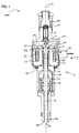
- Figure 1 shows an injection valve 100 according to an exemplary embodiment.
- the injection valve 100 is embodied as an injection valve of outward opening type and may in particular be suitable for dosing fuel to an internal combustion engine.
- the embodiment of Figure 1 is shown in order to describe the general principle of a direct driven electro-magnetic outward opening injection valve.
- the injection valve 100 comprises a valve assembly 1 and an inlet tube 2 hydraulically and mechanically connected to the valve assembly 1.
- the valve assembly 1 includes a valve body 10 with a central longitudinal axis L.
- the valve body 10 further comprises a cavity 11.
- the cavity 11 accommodates a valve needle 4 and an armature 5.
- a pin 50 is arranged along the longitudinal axis L and is fixedly coupled to the armature 5, for example by a press-fit connection and/or a welding connection. Alternatively, the pin 50 can be a part of the armature 5 so that the armature 5 and the pin 50 are a single piece.
- the pin 50 is partly in contact with an inner side of the valve body 10 and serves as guide for the armature 5.
- the valve needle 4 as well as the armature 5 together with the pin 50 are movable along an axial direction, i.e. in a direction running parallel to the central longitudinal axis L.
- the cavity 11 is hydraulically coupled to a recess 20 of the fluid inlet tube 2 and a fuel connector.
- the fuel connector is designed to be connected to a high pressure fuel chamber of an internal combustion engine, in which the fuel is stored under high pressure.
- a main spring 12 is arranged in the cavity 11 between a ring element 13, which is fixedly coupled to the valve needle 4, and a step-like part of the valve body 10.
- the ring element 13 can also be a part of the valve needle 4.
- the main spring 12 is arranged and configured to act on the valve needle 4 to move the valve needle 4 along the axial direction into its closing position, i.e. in an upward direction in Figure 1 .
- a fluid outlet portion 14 is formed, which is closed or opened depending on the axial position of the valve needle 4.
- the valve needle 4 has a groove 40 which is of an annular shape and which allows fluid to flow to the fluid outlet portion 14.
- the fluid outlet portion 14 is closed or opened depending on the axial position of the valve needle 4.
- the valve needle 4 At an axial end of the valve needle 4 facing away from the fluid inlet tube 2, the valve needle 4 has a tip 41.
- the tip 41 is conical. The tip 41 cooperates with the valve body 11 to prevent or enable the fluid flow through the fluid outlet portion 14.
- the fluid is led from the fluid inlet tube 2 into the cavity 11, and, in particular, through the openings 51 of the armature 5 to the lower part of the valve needle 4, to be led on through the groove 40 to the fluid outlet portion 14 near the tip 41 of the valve needle 4.
- the valve needle 4 prevents a fluid flow through the fluid outlet portion 14 in the valve body 11 in a closing position of the valve needle 4.
- the valve assembly 1 is provided with an electro-magnetic actuator unit 3.
- the electro-magnetic actuator unit 3 comprises a coil 30, which is preferably arranged inside a housing 31, which can be part of the valve body 10.
- the coil 30 can be electrically connected via a connector 32.
- the electro-magnetic actuator unit 3 comprises the armature 5.
- the coil 30 is arranged such as to interact with the armature 5, in particular to move the armature 5 along the axial direction into the direction of the fluid outlet portion 14.
- the injection valve 100 comprises a calibration spring 6 that is arranged on the side of the armature 5 which faces away from the fluid outlet portion 14 and which interacts with the armature 5.
- the electro-magnetic actuator unit 3 comprises a pole piece 33, which may also be part of the housing 31. In the closing position of the injection valve 100, there is a gap (not shown) between the armature 5 and the pole piece 33.
- the actuator unit 3 exerts an electro-magnetic force on the armature 5.
- the armature 5 is attracted by the electro-magnetic actuator unit 3 and moves in axial direction towards the fluid outlet portion 14, thereby decreasing the gap between the armature 5 and the pole piece 33.
- the armature 5 takes along the pin 50, which pushes against an end portion 42 of the valve needle 4 distal from the fluid outlet, portion 14.
- the armature 5 and the pin 51 cooperate with the valve needle 4 such that at least part of the lift generated by the coil 30 with respect to the armature 5 is transferred to the valve needle 4, thereby moving the valve needle 5 in an opening position.
- the main spring 12 can force the valve needle 4 to move along the axial direction into its closing position. It depends on the force balance between the force exerted on the valve needle 4 by the actuator unit 3 and the force exerted on the valve needle 4 by the main spring 12 whether the valve needle 4 moves into its closing position or not. In the case that the valve needle 4 moves into its closing position, the pin 51 and thus the armature 5 may decouple from the valve needle 4 due to their inertia.
- a direct driven outward opening injection valve that uses a mechanical contact between the armature 5 and the valve needle 4, as shown in Figure 1 , is very sensitive on parameter changes and difficult to control in stable positions.
- Figure 2 shows a partial view of an injection valve 101 that allows reducing or even avoiding such problems.
- the injection valve 101 is also a direct driven electro-magnetic outward opening injection valve. Except for the differences explained in the following, the injection valve 101 can have the same or similar elements as explained in connection with the injection valve 100, even though not all elements of the injection valve 100 are shown and explained in connection with Figure 2 . Consequently, references numbers, which are referred to in the following but not shown in Figure 2 , refer to the description of Figure 1 .
- the injection valve 101 comprises a valve assembly 1 and a fluid inlet tube 2 with a recess 20, the valve assembly 1 and the fluid tube 2 being connected to each other.
- the valve assembly 1 comprises a valve body 10 with a central longitudinal axis L, wherein the valve body 10 comprises a cavity 11 with a fluid outlet portion 14.
- a valve needle 4 is arranged in the cavity 11 and movable along the central longitudinal axis L between a closing position and opening positions, so that the valve needle 4 can prevent a fluid flow through the fluid outlet portion 14 in the closing position and release the fluid flow through the fluid outlet portion 14 in opening positions.
- the injection valve 101 further comprises an electro-magnetic actuator unit 3 with an electro-magnetic coil 30 being designed to actuate an armature 5, which is arranged in the cavity 11.
- the armature 5, which may comprise a pin 50, is axially moveable relative to the valve needle 4 along the longitudinal axis L.
- the armature 5 of the injection valve 101 is hydraulically coupled to the valve needle 4 and moves the valve needle 4 to an opening position by exerting a hydraulic force when being actuated by the electro-magnetic actuator unit 3.
- the armature 5 is hydraulically coupled to the valve needle 4 by a coupling member 8 arranged between the armature 5 and the valve needle 4.
- the coupling member 8, which is arranged in the cavity 11, may be press-fitted into the valve body 10 or otherwise attached to the valve body 10.
- the coupling member 8 may even be a part of the valve body 10.
- the coupling member 8 forms a first chamber 81 with the armature 5.
- the pin 50 of the armature 5 can form a piston in the first chamber 81.
- the coupling member 8 further forms a second chamber 82 with the valve needle 4.
- the end portion 42 of the valve needle 4 distal from the fluid outlet portion 14 may form a piston in the second chamber 82.
- the first chamber 81 and the second chamber 82 are hydraulically coupled by an orifice 80 in the coupling member 8, which forms a constriction between the chambers 81, 82.
- the first and second chamber 81, 82 are filled with a fluid which in the shown embodiment is the fluid to be injected by the injections valve 101 and which may be for example fuel.
- the first and second chamber 81, 82 are filled with the fluid through gaps 83, 84 which are between the coupling member 8 and the armature 5 and between the coupling member 8 and the valve needle 4, respectively, and which connect the chambers 81, 82 to the cavity 11.
- the gaps 83, 84 are as small as possible to avoid too much leakage but are large enough so that fluid can stream into the chambers 81, 82.
- the armature 5 moves towards the valve needle 4 and the pin 50 moves into the first chamber 81, thereby increasing the pressure inside the first chamber 81. Due to the connection between the first and second chamber 81, 82 by means of the orifice 80, also the pressure in the second chamber 82 increases. Caused by this pressure increase, the force on the valve needle 4 increases in the opening direction so that the hydraulic force exerted by the armature 5 on the valve needle 4 moves the valve needle 4 in an opening position.
- the injection valve 101 further comprises a spring 89, which is designed and such arranged in the valve body 11 to act on the armature 5 to move the armature 5 away from the valve needle 4 and the electro-magnetic actuator unit 3. In particular it is operable to move the armature 5 axially away from the pole piece 33.
- the spring 89 is configured and such arranged in the valve body 11 to increase the gap 35 between the armature 5 and the electro-magnetic actuator unit 3 when the actuator unit 3 is not operated.
- the injection valve 101 can furthermore comprise a stopping member (not shown) for stopping the armature 5 in a closing position to which the armature 5 is pressed by the spring 89.
- a main spring 12 is designed and such arranged in the cavity 11 to act on the valve needle 4 to move the valve needle 4 along the longitudinal axis L into its closing position and/or to retain the valve needle 4 in its closing position when the actuator unit 3 is not operated.
- a diameter of the first chamber 81 may be at least five times as large, preferably at least ten times as large, particularly preferably at least 15 times as large as a diameter of the orifice 80.
- the diameter of the pin 50 in the first chamber may have a value of 3/4 or less, preferably of 2/3 or less of the diameter of the end portion 42 of the valve needle 4 in this or in other embodiments.
- the hydraulic coupling between the armature 5 and the valve needle 4 may have a mechanical advantage of 2 or more, preferably of 3 or more. The mechanical advantage is in particular the ratio of the distance travelled by the armature 5 to the distance travelled by the valve needle 4.
- the initial gap 35 between the armature 5 and the pole piece 33 can be increased in the injection valve 101 compared to the injection valve 100, since the magnetic force is proportional to the reciprocal square of the size of the gap 35.
- the size of the initial gap 35 may be 200 ⁇ m or larger, preferably 300 ⁇ m or larger.
- the air gap 35 in the injection valve 101 is large enough so that the influence of the gap 35 on the magnetic force is as small as possible and so that the injection valve 101 can be driven completely in a ballistic mode, which means that during the complete opening time the valve needle 4 and in particular also the armature 5 is/are in motion and that no stopper is required.
- the armature 5 is always spaced apart from the pole piece 33 throughout the operation of the injection valve 101.
- injection valve 101 are suitable also for other embodiments of the injection valve either alone or in combination.
- Figure 3 shows the Ti-map for the injection valve 101 for a fluid pressure of 100 bar. Due to the absence of a stopper and the possibility to completely drive the injection valve 101 in a ballistic mode, the Ti-map shows a linear behavior of the injection quantity IQ depending on the injection time Ti without ripples or other irregularities.
- Figure 4 shows the needle lift NL during a time T for injection times Ti between 0.22 ms and 2.5 ms, whereas in Figure 5 the corresponding armature lift AL is shown.
- the maximum needle lift is approximately 60 to 70 ⁇ m. From both Figures 4 and 5 , it becomes apparent that the valve needle 4 and the armature 5 are completely driven in a ballistic mode.
- Figure 6 shows the Ti-map for various pressures between 5 bar and 100 bar. As can be seen, independently from the fluid pressure the Ti-map always shows a linear behavior.
- a force of approximately 56 N is needed at the valve needle 4 in order to open the valve needle 4.
- the required pressure increase in the chambers 81, 82 is approximately 80 bar, which leads to a required magnetic force for opening of approximately 20 N.
- the peak and hold current of the coil 30 has to be increased with decreasing pressure.
- a force of approximately 158 N is needed at the valve needle 4 in order to open the valve needle 4, which leads to a required pressure increase in the chambers 81, 82 of approximately 220 bar.
- the simulations have also revealed that the needle opening velocity at the first 10 ⁇ m needle lift is higher compared to the injector concept shown in Figure 1 , whereas the needle opening velocity at higher lifts is lower than the velocity for the injector concept of Figure 1 , since in the injection valve 101 the armature is accelerated alone, i.e. without the valve needle, by the coil until the pressure is reached in the chambers 81, 82 to open the needle.
- Figure 7 shows a further embodiment for an injection valve 102, which, in contrast to the injection valve 101 of Figure 2 , has the first chamber 81 and the second chamber 82 sealed from the cavity 11 by sealing members 85 between the coupling member 8 and the armature 5 and between the coupling member 8 and the valve needle 4.
- the sealing members 85 can be O-rings.
- the chambers 81, 82 are sealed form the cavity 11, the chambers 81, 82 have to be filled when the injection valve 102 is manufactured.
- constraints regarding the clearances of the gaps 83, 84 and regarding the length of the gaps 83, 84, which influence the functionality and stability of the injection valve 101 of Figure 2 can possibly be avoided by the embodiment shown in Figure 7 .
Landscapes
- Engineering & Computer Science (AREA)
- Chemical & Material Sciences (AREA)
- Combustion & Propulsion (AREA)
- Mechanical Engineering (AREA)
- General Engineering & Computer Science (AREA)
- Physics & Mathematics (AREA)
- Electromagnetism (AREA)
- Fuel-Injection Apparatus (AREA)
Abstract
Description
- The invention is related to an injection valve, in particular to a direct driven electro-magnetic outward opening injection valve.
- Direct driven electro-magnetic outward opening injection valves have an injection nozzle that is opened in an outward direction by lifting a valve needle from a seat plate by the action of an electro-magnetic actuator. Such outward opening injectors can be very sensitive to parameter changes and therefore difficult to control in stable opening positions. For instance, they can be very sensitive to pressure deviations due to a high nozzle sealing diameter. Usually, an outward opening injector has a linear flow-lift characteristic with a high flow so that small deviations in the needle lift lead to high quantity deviations. Due to the high sensitivity, the injector does not reach a stable position at another level when the opening force differs but begins to oscillate, which leads to non-linearities in the so-called Ti-Map, which represents the dependency of the injection quantity from the opening time ("Ti") of the valve. Further, it is very difficult to control an outward opening injector with an extended ballistic current profile. By increasing not or too much the hold current value, the known outward opening injectors usually do not reach a stable position.
- It is known to use a needle stopper, which limits the needle lift in order to hold the valve needle in a certain predetermined opening position. However, by using a needle stopper, non-linearities with an S-shape appear in the Ti-Map when the needle reaches the stopper due to the impact of the needle on the stopper. Further, due to the contact stiffness between the needle and the stopper, a small deformation of the stopper can be observed after the needle has contacted the stopper, which leads to oscillations of the needle lift causing ripples in the Ti-Map. In case of a high-flow nozzle with a linear flow-lift characteristic, small deviations in the stopper or needle position lead to high injection quantity deviations. Simulations have shown that, when using a rigid stopper, typical oscillations of the needle lift are on the order of +/- 2 µm, which can lead to a quantity deviation of the injection quantity of more than +/- 5%, so that the detection of the absolute lift value is necessary.
- By using a flexible needle stopper, the needle displacement is defined by a damped oscillation until the needle rests in a stable position. The lower the stopper stiffness is the higher the oscillation amplitude is, so that decreasing the stopper stiffness helps to decrease the S-shaped non-linearities but leads to increased ripples for higher injection times.
- An object to be solved is to provide an injection valve that avoids or at least reduces the above-mentioned problems.
- This object is, inter alia, achieved with an injection valve according to
independent claim 1. Further embodiments and configurations are subject matter of the dependent claims. - According to an embodiment, an injection valve comprises a fluid inlet tube with a recess. The fluid inlet tube is connected to a valve assembly, which comprises a valve body having a central longitudinal axis. The central longitudinal axis defines an "axial direction" so that a movement in an axial direction denotes a movement along the central longitudinal axis.
- According to a further embodiment, the valve body comprises a cavity with a fluid outlet portion. A valve needle is arranged in the cavity of the valve body and is movable in the cavity along the central longitudinal axis between a closing position and opening positions, the valve needle preventing a fluid flow through the fluid outlet portion in a closing position and releasing the fluid flow through the fluid outlet portion in other positions which are the opening positions.
- According to a further embodiment, the injection valve comprises an electro-magnetic actuator unit being designed to actuate an armature, which is arranged in the cavity and is axially moveable relative to the valve needle along the longitudinal axis. The armature is hydraulically coupled to the valve needle and can move the valve needle to an opening position by exerting a hydraulic force when being actuated by the electro-magnetic actuator unit. In particular, when being actuated by the electro-magnetic actuator unit, the armature moves the valve needle to an opening position completely by a hydraulic force. This means that the armature has no direct or indirect mechanical connection or contact to the valve needle for actuating the valve needle but acts on the valve needle only by pressing on a fluid, which, in turn, presses on the valve needle.
- According to a further embodiment, the injection valve comprises a coupling member hydraulically coupling the armature to the valve needle. The coupling member is arranged between the armature and the valve needle and forms a first chamber with the armature and a second chamber with the valve needle, wherein the first and second chambers are filled with a fluid and the first chamber and the second chamber are hydraulically coupled by an orifice in the coupling member. In particular, the armature can comprise a pin, which forms a piston in the first chamber. An end portion of the valve needle distal from the fluid outlet portion can form a piston in the second chamber. When the armature is moved towards the valve needle, the fluid in the first chamber is pressed through the orifice in the coupling member into the second chamber, thereby exerting a pressure force on the valve needle so that the valve needle is moved in an axial direction to an opening position.
- Simulations have shown that an injection valve as described herein, which in particular can be embodied as a direct driven electro-magnetic outward opening injection valve and which can be driven completely in a so-called ballistic mode, which means that during the complete opening time the valve needle is in motion and that no stopper is required, shows a linear Ti-map behavior. Thus, irregularities in the Ti-map, as described above, can be avoided.
- Further exemplary embodiments are explained in the following with the aid of schematic drawings. In the Figures,
- Figure 1
- shows an injection valve in a longitudinal sectional view,
- Figure 2
- shows a detail view of a section of an injection valve,
- Figures 3 to 6
- show exemplary simulation results for the injection valve of
Figure 2 , - Figure 7
- shows a detail view of a section of an injection valve.
- In these figures, elements of the same design and/or function are identified by the same reference numerals.
-
Figure 1 shows aninjection valve 100 according to an exemplary embodiment. In this exemplary embodiment, theinjection valve 100 is embodied as an injection valve of outward opening type and may in particular be suitable for dosing fuel to an internal combustion engine. The embodiment ofFigure 1 is shown in order to describe the general principle of a direct driven electro-magnetic outward opening injection valve. - The
injection valve 100 comprises avalve assembly 1 and aninlet tube 2 hydraulically and mechanically connected to thevalve assembly 1. Thevalve assembly 1 includes avalve body 10 with a central longitudinal axis L. Thevalve body 10 further comprises acavity 11. Thecavity 11 accommodates avalve needle 4 and an armature 5. Apin 50 is arranged along the longitudinal axis L and is fixedly coupled to the armature 5, for example by a press-fit connection and/or a welding connection. Alternatively, thepin 50 can be a part of the armature 5 so that the armature 5 and thepin 50 are a single piece. Thepin 50 is partly in contact with an inner side of thevalve body 10 and serves as guide for the armature 5. Thevalve needle 4 as well as the armature 5 together with thepin 50 are movable along an axial direction, i.e. in a direction running parallel to the central longitudinal axis L. - Due to
openings 51 in the armature 5, thecavity 11 is hydraulically coupled to arecess 20 of thefluid inlet tube 2 and a fuel connector. The fuel connector is designed to be connected to a high pressure fuel chamber of an internal combustion engine, in which the fuel is stored under high pressure. - A
main spring 12 is arranged in thecavity 11 between aring element 13, which is fixedly coupled to thevalve needle 4, and a step-like part of thevalve body 10. Thering element 13 can also be a part of thevalve needle 4. Themain spring 12 is arranged and configured to act on thevalve needle 4 to move thevalve needle 4 along the axial direction into its closing position, i.e. in an upward direction inFigure 1 . - On the free end of the
valve body 10 facing away from theinlet tube 2, afluid outlet portion 14 is formed, which is closed or opened depending on the axial position of thevalve needle 4. Outside the closing position of thevalve needle 4, there is a gap between thevalve body 11 and thevalve needle 4 at an axial end of theinjection valve 100 facing away from theinlet tube 2, the gap forming a valve nozzle. Furthermore, thevalve needle 4 has agroove 40 which is of an annular shape and which allows fluid to flow to thefluid outlet portion 14. Thefluid outlet portion 14 is closed or opened depending on the axial position of thevalve needle 4. - At an axial end of the
valve needle 4 facing away from thefluid inlet tube 2, thevalve needle 4 has atip 41. Preferably, thetip 41 is conical. Thetip 41 cooperates with thevalve body 11 to prevent or enable the fluid flow through thefluid outlet portion 14. - The fluid is led from the
fluid inlet tube 2 into thecavity 11, and, in particular, through theopenings 51 of the armature 5 to the lower part of thevalve needle 4, to be led on through thegroove 40 to thefluid outlet portion 14 near thetip 41 of thevalve needle 4. Thevalve needle 4 prevents a fluid flow through thefluid outlet portion 14 in thevalve body 11 in a closing position of thevalve needle 4. - The
valve assembly 1 is provided with an electro-magnetic actuator unit 3. The electro-magnetic actuator unit 3 comprises acoil 30, which is preferably arranged inside ahousing 31, which can be part of thevalve body 10. Thecoil 30 can be electrically connected via aconnector 32. Furthermore, the electro-magnetic actuator unit 3 comprises the armature 5. Thecoil 30 is arranged such as to interact with the armature 5, in particular to move the armature 5 along the axial direction into the direction of thefluid outlet portion 14. Furthermore, theinjection valve 100 comprises acalibration spring 6 that is arranged on the side of the armature 5 which faces away from thefluid outlet portion 14 and which interacts with the armature 5. - Between the
housing 31 and the armature 5, the electro-magnetic actuator unit 3 comprises apole piece 33, which may also be part of thehousing 31. In the closing position of theinjection valve 100, there is a gap (not shown) between the armature 5 and thepole piece 33. - If the electro-
magnetic actuator unit 3 with thecoil 30 is sufficiently energized, theactuator unit 3 exerts an electro-magnetic force on the armature 5. The armature 5 is attracted by the electro-magnetic actuator unit 3 and moves in axial direction towards thefluid outlet portion 14, thereby decreasing the gap between the armature 5 and thepole piece 33. The armature 5 takes along thepin 50, which pushes against anend portion 42 of thevalve needle 4 distal from the fluid outlet,portion 14. Due to the mechanical contact between thepin 51 and theend portion 42 of thevalve needle 4 the armature 5 and thepin 51 cooperate with thevalve needle 4 such that at least part of the lift generated by thecoil 30 with respect to the armature 5 is transferred to thevalve needle 4, thereby moving the valve needle 5 in an opening position. - In the case that the
actuator unit 3 is de-energized, themain spring 12 can force thevalve needle 4 to move along the axial direction into its closing position. It depends on the force balance between the force exerted on thevalve needle 4 by theactuator unit 3 and the force exerted on thevalve needle 4 by themain spring 12 whether thevalve needle 4 moves into its closing position or not. In the case that thevalve needle 4 moves into its closing position, thepin 51 and thus the armature 5 may decouple from thevalve needle 4 due to their inertia. - As explained above in the general part, a direct driven outward opening injection valve that uses a mechanical contact between the armature 5 and the
valve needle 4, as shown inFigure 1 , is very sensitive on parameter changes and difficult to control in stable positions. -
Figure 2 shows a partial view of an injection valve 101 that allows reducing or even avoiding such problems. - Similar to the
injection valve 100, the injection valve 101 is also a direct driven electro-magnetic outward opening injection valve. Except for the differences explained in the following, the injection valve 101 can have the same or similar elements as explained in connection with theinjection valve 100, even though not all elements of theinjection valve 100 are shown and explained in connection withFigure 2 . Consequently, references numbers, which are referred to in the following but not shown inFigure 2 , refer to the description ofFigure 1 . - As already explained in connection with the
injection valve 100, also the injection valve 101 comprises avalve assembly 1 and afluid inlet tube 2 with arecess 20, thevalve assembly 1 and thefluid tube 2 being connected to each other. Thevalve assembly 1 comprises avalve body 10 with a central longitudinal axis L, wherein thevalve body 10 comprises acavity 11 with afluid outlet portion 14. Avalve needle 4 is arranged in thecavity 11 and movable along the central longitudinal axis L between a closing position and opening positions, so that thevalve needle 4 can prevent a fluid flow through thefluid outlet portion 14 in the closing position and release the fluid flow through thefluid outlet portion 14 in opening positions. - The injection valve 101 further comprises an electro-
magnetic actuator unit 3 with an electro-magnetic coil 30 being designed to actuate an armature 5, which is arranged in thecavity 11. The armature 5, which may comprise apin 50, is axially moveable relative to thevalve needle 4 along the longitudinal axis L. - In contrast to the armature 5 being mechanically coupled to the
valve needle 4 as shown inFigure 1 , the armature 5 of the injection valve 101 is hydraulically coupled to thevalve needle 4 and moves thevalve needle 4 to an opening position by exerting a hydraulic force when being actuated by the electro-magnetic actuator unit 3. - In particular, the armature 5 is hydraulically coupled to the
valve needle 4 by acoupling member 8 arranged between the armature 5 and thevalve needle 4. Thecoupling member 8, which is arranged in thecavity 11, may be press-fitted into thevalve body 10 or otherwise attached to thevalve body 10. Thecoupling member 8 may even be a part of thevalve body 10. Thecoupling member 8 forms afirst chamber 81 with the armature 5. In particular, thepin 50 of the armature 5 can form a piston in thefirst chamber 81. Thecoupling member 8 further forms asecond chamber 82 with thevalve needle 4. In particular, theend portion 42 of thevalve needle 4 distal from thefluid outlet portion 14 may form a piston in thesecond chamber 82. Thefirst chamber 81 and thesecond chamber 82 are hydraulically coupled by anorifice 80 in thecoupling member 8, which forms a constriction between thechambers - The first and
second chamber second chamber gaps coupling member 8 and the armature 5 and between thecoupling member 8 and thevalve needle 4, respectively, and which connect thechambers cavity 11. Preferably, thegaps chambers - By actuating the electro-
magnetic actuator unit 3, the armature 5 moves towards thevalve needle 4 and thepin 50 moves into thefirst chamber 81, thereby increasing the pressure inside thefirst chamber 81. Due to the connection between the first andsecond chamber orifice 80, also the pressure in thesecond chamber 82 increases. Caused by this pressure increase, the force on thevalve needle 4 increases in the opening direction so that the hydraulic force exerted by the armature 5 on thevalve needle 4 moves thevalve needle 4 in an opening position. - The injection valve 101 further comprises a
spring 89, which is designed and such arranged in thevalve body 11 to act on the armature 5 to move the armature 5 away from thevalve needle 4 and the electro-magnetic actuator unit 3. In particular it is operable to move the armature 5 axially away from thepole piece 33. In particular, thespring 89 is configured and such arranged in thevalve body 11 to increase thegap 35 between the armature 5 and the electro-magnetic actuator unit 3 when theactuator unit 3 is not operated. The injection valve 101 can furthermore comprise a stopping member (not shown) for stopping the armature 5 in a closing position to which the armature 5 is pressed by thespring 89. As explained in connection withFigure 1 , amain spring 12 is designed and such arranged in thecavity 11 to act on thevalve needle 4 to move thevalve needle 4 along the longitudinal axis L into its closing position and/or to retain thevalve needle 4 in its closing position when theactuator unit 3 is not operated. - While actuating the electro-
magnetic actuator unit 3, theorifice 80 acts as a damping orifice so that pressure oscillations inside thechambers first chamber 81 may be at least five times as large, preferably at least ten times as large, particularly preferably at least 15 times as large as a diameter of theorifice 80. - Due to a proper ratio between the piston areas in the first and
second chamber injection valve 100 shown inFigure 1 . For example, the diameter of thepin 50 in the first chamber may have a value of 3/4 or less, preferably of 2/3 or less of the diameter of theend portion 42 of thevalve needle 4 in this or in other embodiments. The hydraulic coupling between the armature 5 and thevalve needle 4 may have a mechanical advantage of 2 or more, preferably of 3 or more. The mechanical advantage is in particular the ratio of the distance travelled by the armature 5 to the distance travelled by thevalve needle 4. - As a consequence, the
initial gap 35 between the armature 5 and thepole piece 33 can be increased in the injection valve 101 compared to theinjection valve 100, since the magnetic force is proportional to the reciprocal square of the size of thegap 35. For example, the size of theinitial gap 35 may be 200 µm or larger, preferably 300 µm or larger. In other words, the closer the armature comes to the pole piece, the higher the magnetic force becomes, which results in a higher acceleration in the opening direction and which can lead to a contact between the armature 5 and thepole piece 33 in theinjection valve 100. As a consequence, theair gap 35 in the injection valve 101 is large enough so that the influence of thegap 35 on the magnetic force is as small as possible and so that the injection valve 101 can be driven completely in a ballistic mode, which means that during the complete opening time thevalve needle 4 and in particular also the armature 5 is/are in motion and that no stopper is required. Preferably, the armature 5 is always spaced apart from thepole piece 33 throughout the operation of the injection valve 101. - In order to demonstrate the capability of the injection valve 101, simulations are shown in connection with
Figures 3 to 6 . For the simulations, a linear flow-lift characteristic has been assumed and the following parameters have been taken into account: - initial (maximal) gap 35: 300 µm
- minimal gap 35: 100 µm
- initial volume of first chamber 81: approx. 3 mm3
- initial volume of second chamber 82: approx. 5 mm3
- diameter of orifice 80: 0.1 mm
- force of spring 89: 3 N
- force of main spring 12: 160 N
- piston diameter in first chamber 81: 1.8 mm
- piston diameter in second chamber 82: 3 mm
- clearance of
gaps 83, 84: 3 µm - length of
gaps 83, 84: approx. 10 mm - These parameters of the injection valve 101 are suitable also for other embodiments of the injection valve either alone or in combination.
-
Figure 3 shows the Ti-map for the injection valve 101 for a fluid pressure of 100 bar. Due to the absence of a stopper and the possibility to completely drive the injection valve 101 in a ballistic mode, the Ti-map shows a linear behavior of the injection quantity IQ depending on the injection time Ti without ripples or other irregularities. -
Figure 4 shows the needle lift NL during a time T for injection times Ti between 0.22 ms and 2.5 ms, whereas inFigure 5 the corresponding armature lift AL is shown. As can be seen inFigure 4 , the maximum needle lift is approximately 60 to 70 µm. From bothFigures 4 and 5 , it becomes apparent that thevalve needle 4 and the armature 5 are completely driven in a ballistic mode. -
Figure 6 shows the Ti-map for various pressures between 5 bar and 100 bar. As can be seen, independently from the fluid pressure the Ti-map always shows a linear behavior. - According to the simulations, at a fluid pressure of 100 bar a force of approximately 56 N is needed at the
valve needle 4 in order to open thevalve needle 4. The required pressure increase in thechambers coil 30 has to be increased with decreasing pressure. For example, for a fluid pressure of 5 bar a force of approximately 158 N is needed at thevalve needle 4 in order to open thevalve needle 4, which leads to a required pressure increase in thechambers - The simulations have also revealed that the needle opening velocity at the first 10 µm needle lift is higher compared to the injector concept shown in
Figure 1 , whereas the needle opening velocity at higher lifts is lower than the velocity for the injector concept ofFigure 1 , since in the injection valve 101 the armature is accelerated alone, i.e. without the valve needle, by the coil until the pressure is reached in thechambers -
Figure 7 shows a further embodiment for aninjection valve 102, which, in contrast to the injection valve 101 ofFigure 2 , has thefirst chamber 81 and thesecond chamber 82 sealed from thecavity 11 by sealingmembers 85 between thecoupling member 8 and the armature 5 and between thecoupling member 8 and thevalve needle 4. For example, the sealingmembers 85 can be O-rings. - Since the
chambers cavity 11, thechambers injection valve 102 is manufactured. However, constraints regarding the clearances of thegaps gaps Figure 2 , can possibly be avoided by the embodiment shown inFigure 7 . - As described above, it is possible to drive the
injection valves 101, 102 only in ballistic mode, which requires a low magnetic force dependency on the lift orgap 35 between the armature 5 and thepole piece 33. Due to the high distance between thepole piece 33 and the armature 5, the absolute magnetic force value decreases. Nevertheless, the required high opening force can be achieved with the hydraulic leverage described above. As it is possible to drive the injection valve described herein only in ballistic mode but directly driven, without a stopper and with low magnetic force, an outward opening injection valve with an electro-magnetic actuator with a linear Ti-map is feasible.
Claims (10)
- Injection valve (101, 102), comprising
a valve assembly (1) and a fluid inlet tube (2) with a recess (20) connected to the valve assembly (1), the valve assembly (1) comprising a valve body (10) having a central longitudinal axis (L), the valve body (10) comprising a cavity (11) with a fluid outlet portion (14),
a valve needle (4) arranged in the cavity (11) and movable along the central longitudinal axis (L) between a closing position and opening positions, the valve needle (4) preventing a fluid flow through the fluid outlet portion (14) in the closing position and releasing the fluid flow through the fluid outlet portion (14) in opening positions,
an electro-magnetic actuator unit (3) being designed to actuate an armature (5) which is arranged in the cavity (11) and is axially moveable relative to the valve needle (4) along the longitudinal axis (L),
wherein the armature (5) is hydraulically coupled to the valve needle (4) and is operable to move the valve needle (4) to an opening position by exerting a hydraulic force when being actuated by the electro-magnetic actuator unit (3). - Injection valve (101, 102) according to claim 1, wherein the armature (5) is hydraulically coupled to the valve needle (4) by a coupling member (8) arranged between the armature (5) and the valve needle (4), wherein the coupling member (8) forms a first chamber (81) with the armature (5) and a second chamber (82) with the valve needle (4), the first chamber (81) and the second chamber (82) being hydraulically coupled by an orifice (80) in the coupling member (8).
- Injection valve (101, 102) according to claim 2, wherein the armature (5) comprises a pin (50) which forms a piston in the first chamber (81) and wherein an end portion (42) of the valve needle (4) distal from the fluid outlet portion (14) forms a piston in the second chamber (82).
- Injection valve (101, 102) according to claim 2 or 3, wherein the first chamber (81) and the second chamber (82) are connected to the cavity (11) by gaps (83, 84) between the coupling member (8) and the armature (5) and between the coupling member (8) and the valve needle (4).
- Injection valve (101, 102) according to claim 2 or 3, wherein the first chamber (81) and the second chamber (82) are sealed from the cavity (11) by sealing members (85) between the coupling member (8) and the armature (5) and between the coupling member (8) and the valve needle (4).
- Injection valve (101, 102) according to claim 5, wherein the sealing members (85) are O-rings.
- Injection valve (101, 102) according to any of the preceding claims, wherein a spring (89) is configured and such arranged in the valve body (11) to act on the armature (5) to move the armature (5) away from the valve needle (4).
- Injection valve (101, 102) according to claim 7, wherein the spring (89) is configured and such arranged in the valve body (11) to increase a gap (35) between the armature (5) and the electro-magnetic actuator unit (3).
- Injection valve (101, 102) according to any of the preceding claims, wherein a main spring (12) is configured and such arranged in the cavity (11) to act on the valve needle (4) to move the valve needle (4) along the longitudinal axis (L) into its closing position and/or to retain the valve needle (4) in its closing position.
- Injection valve (101, 102) according to any of the preceding claims, wherein the injection valve (101, 102) is a direct driven electro-magnetic outward opening injection valve.
Priority Applications (1)
| Application Number | Priority Date | Filing Date | Title |
|---|---|---|---|
| EP13188793.7A EP2863044B1 (en) | 2013-10-15 | 2013-10-15 | Injection valve |
Applications Claiming Priority (1)
| Application Number | Priority Date | Filing Date | Title |
|---|---|---|---|
| EP13188793.7A EP2863044B1 (en) | 2013-10-15 | 2013-10-15 | Injection valve |
Publications (2)
| Publication Number | Publication Date |
|---|---|
| EP2863044A1 true EP2863044A1 (en) | 2015-04-22 |
| EP2863044B1 EP2863044B1 (en) | 2016-06-29 |
Family
ID=49378140
Family Applications (1)
| Application Number | Title | Priority Date | Filing Date |
|---|---|---|---|
| EP13188793.7A Not-in-force EP2863044B1 (en) | 2013-10-15 | 2013-10-15 | Injection valve |
Country Status (1)
| Country | Link |
|---|---|
| EP (1) | EP2863044B1 (en) |
Citations (7)
| Publication number | Priority date | Publication date | Assignee | Title |
|---|---|---|---|---|
| EP0903490A1 (en) * | 1997-03-25 | 1999-03-24 | Isuzu Motors Limited | Injector |
| DE102007001363A1 (en) * | 2007-01-09 | 2008-07-10 | Robert Bosch Gmbh | Injector for injecting fuel into combustion chambers of internal combustion engines |
| EP2123899A1 (en) * | 2008-05-23 | 2009-11-25 | Delphi Technologies, Inc. | Fuel injector with a solenoid actuator |
| EP2365205A1 (en) * | 2010-03-03 | 2011-09-14 | Continental Automotive GmbH | Injection valve |
| DE102010002845A1 (en) * | 2010-03-15 | 2011-09-15 | Robert Bosch Gmbh | Fuel injector |
| EP2369165A2 (en) * | 2010-03-26 | 2011-09-28 | Robert Bosch GmbH | Fuel injector |
| DE102010027278A1 (en) * | 2010-07-15 | 2012-01-19 | Siemens Aktiengesellschaft | Thermally volume-neutral stroke transformer, in particular for a metering valve without hydraulic compensator |
-
2013
- 2013-10-15 EP EP13188793.7A patent/EP2863044B1/en not_active Not-in-force
Patent Citations (7)
| Publication number | Priority date | Publication date | Assignee | Title |
|---|---|---|---|---|
| EP0903490A1 (en) * | 1997-03-25 | 1999-03-24 | Isuzu Motors Limited | Injector |
| DE102007001363A1 (en) * | 2007-01-09 | 2008-07-10 | Robert Bosch Gmbh | Injector for injecting fuel into combustion chambers of internal combustion engines |
| EP2123899A1 (en) * | 2008-05-23 | 2009-11-25 | Delphi Technologies, Inc. | Fuel injector with a solenoid actuator |
| EP2365205A1 (en) * | 2010-03-03 | 2011-09-14 | Continental Automotive GmbH | Injection valve |
| DE102010002845A1 (en) * | 2010-03-15 | 2011-09-15 | Robert Bosch Gmbh | Fuel injector |
| EP2369165A2 (en) * | 2010-03-26 | 2011-09-28 | Robert Bosch GmbH | Fuel injector |
| DE102010027278A1 (en) * | 2010-07-15 | 2012-01-19 | Siemens Aktiengesellschaft | Thermally volume-neutral stroke transformer, in particular for a metering valve without hydraulic compensator |
Also Published As
| Publication number | Publication date |
|---|---|
| EP2863044B1 (en) | 2016-06-29 |
Similar Documents
| Publication | Publication Date | Title |
|---|---|---|
| JP5064446B2 (en) | Highly stable fuel injection device for internal combustion engines | |
| KR101223851B1 (en) | Fuel injection system with high repeatability and stability of operation for an internal-combustion engine | |
| US9664161B2 (en) | Valve assembly for an injection valve and injection valve | |
| KR102301677B1 (en) | Fuel injector | |
| US9435305B2 (en) | Valve assembly for an injection valve and injection valve | |
| CN105275695B (en) | Fuel injector | |
| CN104411963B (en) | Valve module and injection valve for injection valve | |
| CN107709751B (en) | Electromagnetic valve | |
| KR101947249B1 (en) | Injector for a combustion engine | |
| CN101529081B (en) | Injector with an axial pressure-compensating control valve | |
| CN110100089B (en) | Valve for dispensing a fluid | |
| JP6655723B2 (en) | Fuel injection valve | |
| US9995262B2 (en) | Fluid injection valve | |
| JP2004511718A (en) | Magnet valve for controlling the injection valve of an internal combustion engine | |
| CN108368807B (en) | Valve Assemblies and Fluid Injection Valves | |
| KR102706038B1 (en) | Fluid metering valve | |
| KR102139895B1 (en) | Injection valve with magnetic ring element | |
| EP2863044A1 (en) | Injection valve | |
| CN106930881A (en) | Valve for measuring fluid | |
| WO2019163383A1 (en) | Fuel injection valve and method for assembling same | |
| EP2067981B1 (en) | Valve assembly for an injection valve and injection valve | |
| EP3611368A1 (en) | Valve assembly and fuel injection valve |
Legal Events
| Date | Code | Title | Description |
|---|---|---|---|
| PUAI | Public reference made under article 153(3) epc to a published international application that has entered the european phase |
Free format text: ORIGINAL CODE: 0009012 |
|
| 17P | Request for examination filed |
Effective date: 20131015 |
|
| AK | Designated contracting states |
Kind code of ref document: A1 Designated state(s): AL AT BE BG CH CY CZ DE DK EE ES FI FR GB GR HR HU IE IS IT LI LT LU LV MC MK MT NL NO PL PT RO RS SE SI SK SM TR |
|
| AX | Request for extension of the european patent |
Extension state: BA ME |
|
| R17P | Request for examination filed (corrected) |
Effective date: 20151022 |
|
| RBV | Designated contracting states (corrected) |
Designated state(s): AL AT BE BG CH CY CZ DE DK EE ES FI FR GB GR HR HU IE IS IT LI LT LU LV MC MK MT NL NO PL PT RO RS SE SI SK SM TR |
|
| GRAP | Despatch of communication of intention to grant a patent |
Free format text: ORIGINAL CODE: EPIDOSNIGR1 |
|
| INTG | Intention to grant announced |
Effective date: 20160203 |
|
| GRAS | Grant fee paid |
Free format text: ORIGINAL CODE: EPIDOSNIGR3 |
|
| GRAA | (expected) grant |
Free format text: ORIGINAL CODE: 0009210 |
|
| AK | Designated contracting states |
Kind code of ref document: B1 Designated state(s): AL AT BE BG CH CY CZ DE DK EE ES FI FR GB GR HR HU IE IS IT LI LT LU LV MC MK MT NL NO PL PT RO RS SE SI SK SM TR |
|
| REG | Reference to a national code |
Ref country code: GB Ref legal event code: FG4D |
|
| REG | Reference to a national code |
Ref country code: CH Ref legal event code: EP |
|
| REG | Reference to a national code |
Ref country code: AT Ref legal event code: REF Ref document number: 809306 Country of ref document: AT Kind code of ref document: T Effective date: 20160715 |
|
| REG | Reference to a national code |
Ref country code: IE Ref legal event code: FG4D |
|
| REG | Reference to a national code |
Ref country code: DE Ref legal event code: R096 Ref document number: 602013008883 Country of ref document: DE |
|
| REG | Reference to a national code |
Ref country code: FR Ref legal event code: PLFP Year of fee payment: 4 |
|
| REG | Reference to a national code |
Ref country code: LT Ref legal event code: MG4D |
|
| PG25 | Lapsed in a contracting state [announced via postgrant information from national office to epo] |
Ref country code: LT Free format text: LAPSE BECAUSE OF FAILURE TO SUBMIT A TRANSLATION OF THE DESCRIPTION OR TO PAY THE FEE WITHIN THE PRESCRIBED TIME-LIMIT Effective date: 20160629 Ref country code: NO Free format text: LAPSE BECAUSE OF FAILURE TO SUBMIT A TRANSLATION OF THE DESCRIPTION OR TO PAY THE FEE WITHIN THE PRESCRIBED TIME-LIMIT Effective date: 20160929 Ref country code: FI Free format text: LAPSE BECAUSE OF FAILURE TO SUBMIT A TRANSLATION OF THE DESCRIPTION OR TO PAY THE FEE WITHIN THE PRESCRIBED TIME-LIMIT Effective date: 20160629 |
|
| REG | Reference to a national code |
Ref country code: NL Ref legal event code: MP Effective date: 20160629 |
|
| PG25 | Lapsed in a contracting state [announced via postgrant information from national office to epo] |
Ref country code: GR Free format text: LAPSE BECAUSE OF FAILURE TO SUBMIT A TRANSLATION OF THE DESCRIPTION OR TO PAY THE FEE WITHIN THE PRESCRIBED TIME-LIMIT Effective date: 20160930 Ref country code: RS Free format text: LAPSE BECAUSE OF FAILURE TO SUBMIT A TRANSLATION OF THE DESCRIPTION OR TO PAY THE FEE WITHIN THE PRESCRIBED TIME-LIMIT Effective date: 20160629 Ref country code: LV Free format text: LAPSE BECAUSE OF FAILURE TO SUBMIT A TRANSLATION OF THE DESCRIPTION OR TO PAY THE FEE WITHIN THE PRESCRIBED TIME-LIMIT Effective date: 20160629 Ref country code: HR Free format text: LAPSE BECAUSE OF FAILURE TO SUBMIT A TRANSLATION OF THE DESCRIPTION OR TO PAY THE FEE WITHIN THE PRESCRIBED TIME-LIMIT Effective date: 20160629 Ref country code: SE Free format text: LAPSE BECAUSE OF FAILURE TO SUBMIT A TRANSLATION OF THE DESCRIPTION OR TO PAY THE FEE WITHIN THE PRESCRIBED TIME-LIMIT Effective date: 20160629 Ref country code: NL Free format text: LAPSE BECAUSE OF FAILURE TO SUBMIT A TRANSLATION OF THE DESCRIPTION OR TO PAY THE FEE WITHIN THE PRESCRIBED TIME-LIMIT Effective date: 20160629 |
|
| REG | Reference to a national code |
Ref country code: AT Ref legal event code: MK05 Ref document number: 809306 Country of ref document: AT Kind code of ref document: T Effective date: 20160629 |
|
| PG25 | Lapsed in a contracting state [announced via postgrant information from national office to epo] |
Ref country code: IS Free format text: LAPSE BECAUSE OF FAILURE TO SUBMIT A TRANSLATION OF THE DESCRIPTION OR TO PAY THE FEE WITHIN THE PRESCRIBED TIME-LIMIT Effective date: 20161029 Ref country code: CZ Free format text: LAPSE BECAUSE OF FAILURE TO SUBMIT A TRANSLATION OF THE DESCRIPTION OR TO PAY THE FEE WITHIN THE PRESCRIBED TIME-LIMIT Effective date: 20160629 Ref country code: RO Free format text: LAPSE BECAUSE OF FAILURE TO SUBMIT A TRANSLATION OF THE DESCRIPTION OR TO PAY THE FEE WITHIN THE PRESCRIBED TIME-LIMIT Effective date: 20160629 Ref country code: SK Free format text: LAPSE BECAUSE OF FAILURE TO SUBMIT A TRANSLATION OF THE DESCRIPTION OR TO PAY THE FEE WITHIN THE PRESCRIBED TIME-LIMIT Effective date: 20160629 Ref country code: EE Free format text: LAPSE BECAUSE OF FAILURE TO SUBMIT A TRANSLATION OF THE DESCRIPTION OR TO PAY THE FEE WITHIN THE PRESCRIBED TIME-LIMIT Effective date: 20160629 |
|
| PG25 | Lapsed in a contracting state [announced via postgrant information from national office to epo] |
Ref country code: AT Free format text: LAPSE BECAUSE OF FAILURE TO SUBMIT A TRANSLATION OF THE DESCRIPTION OR TO PAY THE FEE WITHIN THE PRESCRIBED TIME-LIMIT Effective date: 20160629 Ref country code: PL Free format text: LAPSE BECAUSE OF FAILURE TO SUBMIT A TRANSLATION OF THE DESCRIPTION OR TO PAY THE FEE WITHIN THE PRESCRIBED TIME-LIMIT Effective date: 20160629 Ref country code: BE Free format text: LAPSE BECAUSE OF NON-PAYMENT OF DUE FEES Effective date: 20160629 Ref country code: SM Free format text: LAPSE BECAUSE OF FAILURE TO SUBMIT A TRANSLATION OF THE DESCRIPTION OR TO PAY THE FEE WITHIN THE PRESCRIBED TIME-LIMIT Effective date: 20160629 Ref country code: ES Free format text: LAPSE BECAUSE OF FAILURE TO SUBMIT A TRANSLATION OF THE DESCRIPTION OR TO PAY THE FEE WITHIN THE PRESCRIBED TIME-LIMIT Effective date: 20160629 Ref country code: PT Free format text: LAPSE BECAUSE OF FAILURE TO SUBMIT A TRANSLATION OF THE DESCRIPTION OR TO PAY THE FEE WITHIN THE PRESCRIBED TIME-LIMIT Effective date: 20161031 |
|
| REG | Reference to a national code |
Ref country code: DE Ref legal event code: R097 Ref document number: 602013008883 Country of ref document: DE |
|
| PG25 | Lapsed in a contracting state [announced via postgrant information from national office to epo] |
Ref country code: DK Free format text: LAPSE BECAUSE OF FAILURE TO SUBMIT A TRANSLATION OF THE DESCRIPTION OR TO PAY THE FEE WITHIN THE PRESCRIBED TIME-LIMIT Effective date: 20160629 |
|
| REG | Reference to a national code |
Ref country code: CH Ref legal event code: PL |
|
| 26N | No opposition filed |
Effective date: 20170330 |
|
| PLBE | No opposition filed within time limit |
Free format text: ORIGINAL CODE: 0009261 |
|
| STAA | Information on the status of an ep patent application or granted ep patent |
Free format text: STATUS: NO OPPOSITION FILED WITHIN TIME LIMIT |
|
| REG | Reference to a national code |
Ref country code: IE Ref legal event code: MM4A |
|
| PG25 | Lapsed in a contracting state [announced via postgrant information from national office to epo] |
Ref country code: LI Free format text: LAPSE BECAUSE OF NON-PAYMENT OF DUE FEES Effective date: 20161031 Ref country code: CH Free format text: LAPSE BECAUSE OF NON-PAYMENT OF DUE FEES Effective date: 20161031 |
|
| PG25 | Lapsed in a contracting state [announced via postgrant information from national office to epo] |
Ref country code: LU Free format text: LAPSE BECAUSE OF NON-PAYMENT OF DUE FEES Effective date: 20161015 Ref country code: BG Free format text: LAPSE BECAUSE OF FAILURE TO SUBMIT A TRANSLATION OF THE DESCRIPTION OR TO PAY THE FEE WITHIN THE PRESCRIBED TIME-LIMIT Effective date: 20160929 Ref country code: SI Free format text: LAPSE BECAUSE OF FAILURE TO SUBMIT A TRANSLATION OF THE DESCRIPTION OR TO PAY THE FEE WITHIN THE PRESCRIBED TIME-LIMIT Effective date: 20160629 |
|
| REG | Reference to a national code |
Ref country code: FR Ref legal event code: PLFP Year of fee payment: 5 |
|
| PG25 | Lapsed in a contracting state [announced via postgrant information from national office to epo] |
Ref country code: IE Free format text: LAPSE BECAUSE OF NON-PAYMENT OF DUE FEES Effective date: 20161015 |
|
| PG25 | Lapsed in a contracting state [announced via postgrant information from national office to epo] |
Ref country code: HU Free format text: LAPSE BECAUSE OF FAILURE TO SUBMIT A TRANSLATION OF THE DESCRIPTION OR TO PAY THE FEE WITHIN THE PRESCRIBED TIME-LIMIT; INVALID AB INITIO Effective date: 20131015 |
|
| GBPC | Gb: european patent ceased through non-payment of renewal fee |
Effective date: 20171015 |
|
| PG25 | Lapsed in a contracting state [announced via postgrant information from national office to epo] |
Ref country code: MC Free format text: LAPSE BECAUSE OF FAILURE TO SUBMIT A TRANSLATION OF THE DESCRIPTION OR TO PAY THE FEE WITHIN THE PRESCRIBED TIME-LIMIT Effective date: 20160629 Ref country code: MT Free format text: LAPSE BECAUSE OF NON-PAYMENT OF DUE FEES Effective date: 20161031 Ref country code: CY Free format text: LAPSE BECAUSE OF FAILURE TO SUBMIT A TRANSLATION OF THE DESCRIPTION OR TO PAY THE FEE WITHIN THE PRESCRIBED TIME-LIMIT Effective date: 20160629 Ref country code: MK Free format text: LAPSE BECAUSE OF FAILURE TO SUBMIT A TRANSLATION OF THE DESCRIPTION OR TO PAY THE FEE WITHIN THE PRESCRIBED TIME-LIMIT Effective date: 20160629 |
|
| PG25 | Lapsed in a contracting state [announced via postgrant information from national office to epo] |
Ref country code: GB Free format text: LAPSE BECAUSE OF NON-PAYMENT OF DUE FEES Effective date: 20171015 |
|
| REG | Reference to a national code |
Ref country code: FR Ref legal event code: PLFP Year of fee payment: 6 |
|
| PG25 | Lapsed in a contracting state [announced via postgrant information from national office to epo] |
Ref country code: TR Free format text: LAPSE BECAUSE OF FAILURE TO SUBMIT A TRANSLATION OF THE DESCRIPTION OR TO PAY THE FEE WITHIN THE PRESCRIBED TIME-LIMIT Effective date: 20160629 Ref country code: AL Free format text: LAPSE BECAUSE OF FAILURE TO SUBMIT A TRANSLATION OF THE DESCRIPTION OR TO PAY THE FEE WITHIN THE PRESCRIBED TIME-LIMIT Effective date: 20160629 |
|
| REG | Reference to a national code |
Ref country code: DE Ref legal event code: R081 Ref document number: 602013008883 Country of ref document: DE Owner name: VITESCO TECHNOLOGIES GMBH, DE Free format text: FORMER OWNER: CONTINENTAL AUTOMOTIVE GMBH, 30165 HANNOVER, DE |
|
| REG | Reference to a national code |
Ref country code: DE Ref legal event code: R081 Ref document number: 602013008883 Country of ref document: DE Owner name: VITESCO TECHNOLOGIES GMBH, DE Free format text: FORMER OWNER: VITESCO TECHNOLOGIES GMBH, 30165 HANNOVER, DE |
|
| REG | Reference to a national code |
Ref country code: DE Ref legal event code: R084 Ref document number: 602013008883 Country of ref document: DE |
|
| P01 | Opt-out of the competence of the unified patent court (upc) registered |
Effective date: 20230530 |
|
| PGFP | Annual fee paid to national office [announced via postgrant information from national office to epo] |
Ref country code: IT Payment date: 20231026 Year of fee payment: 11 Ref country code: FR Payment date: 20231025 Year of fee payment: 11 Ref country code: DE Payment date: 20231031 Year of fee payment: 11 |
|
| REG | Reference to a national code |
Ref country code: DE Ref legal event code: R119 Ref document number: 602013008883 Country of ref document: DE |
|
| PG25 | Lapsed in a contracting state [announced via postgrant information from national office to epo] |
Ref country code: DE Free format text: LAPSE BECAUSE OF NON-PAYMENT OF DUE FEES Effective date: 20250501 |
|
| PG25 | Lapsed in a contracting state [announced via postgrant information from national office to epo] |
Ref country code: FR Free format text: LAPSE BECAUSE OF NON-PAYMENT OF DUE FEES Effective date: 20241031 |
|
| PG25 | Lapsed in a contracting state [announced via postgrant information from national office to epo] |
Ref country code: IT Free format text: LAPSE BECAUSE OF NON-PAYMENT OF DUE FEES Effective date: 20241015 |