EP2863040A1 - Thrust reverser fan ramp partially formed on aft end of fan case - Google Patents
Thrust reverser fan ramp partially formed on aft end of fan case Download PDFInfo
- Publication number
- EP2863040A1 EP2863040A1 EP20140188954 EP14188954A EP2863040A1 EP 2863040 A1 EP2863040 A1 EP 2863040A1 EP 20140188954 EP20140188954 EP 20140188954 EP 14188954 A EP14188954 A EP 14188954A EP 2863040 A1 EP2863040 A1 EP 2863040A1
- Authority
- EP
- European Patent Office
- Prior art keywords
- fan
- fan case
- propulsion system
- aircraft propulsion
- ramp
- Prior art date
- Legal status (The legal status is an assumption and is not a legal conclusion. Google has not performed a legal analysis and makes no representation as to the accuracy of the status listed.)
- Withdrawn
Links
- 238000004806 packaging method and process Methods 0.000 abstract 1
- 238000000034 method Methods 0.000 description 7
- 230000008901 benefit Effects 0.000 description 6
- 230000000712 assembly Effects 0.000 description 2
- 238000000429 assembly Methods 0.000 description 2
- 239000004215 Carbon black (E152) Substances 0.000 description 1
- 238000010276 construction Methods 0.000 description 1
- 230000008878 coupling Effects 0.000 description 1
- 238000010168 coupling process Methods 0.000 description 1
- 238000005859 coupling reaction Methods 0.000 description 1
- 239000000446 fuel Substances 0.000 description 1
- 229930195733 hydrocarbon Natural products 0.000 description 1
- 150000002430 hydrocarbons Chemical class 0.000 description 1
- 239000000463 material Substances 0.000 description 1
- 239000000126 substance Substances 0.000 description 1
Images



Classifications
-
- F—MECHANICAL ENGINEERING; LIGHTING; HEATING; WEAPONS; BLASTING
- F02—COMBUSTION ENGINES; HOT-GAS OR COMBUSTION-PRODUCT ENGINE PLANTS
- F02K—JET-PROPULSION PLANTS
- F02K1/00—Plants characterised by the form or arrangement of the jet pipe or nozzle; Jet pipes or nozzles peculiar thereto
- F02K1/54—Nozzles having means for reversing jet thrust
- F02K1/64—Reversing fan flow
- F02K1/70—Reversing fan flow using thrust reverser flaps or doors mounted on the fan housing
-
- F—MECHANICAL ENGINEERING; LIGHTING; HEATING; WEAPONS; BLASTING
- F02—COMBUSTION ENGINES; HOT-GAS OR COMBUSTION-PRODUCT ENGINE PLANTS
- F02K—JET-PROPULSION PLANTS
- F02K1/00—Plants characterised by the form or arrangement of the jet pipe or nozzle; Jet pipes or nozzles peculiar thereto
- F02K1/54—Nozzles having means for reversing jet thrust
- F02K1/64—Reversing fan flow
- F02K1/70—Reversing fan flow using thrust reverser flaps or doors mounted on the fan housing
- F02K1/72—Reversing fan flow using thrust reverser flaps or doors mounted on the fan housing the aft end of the fan housing being movable to uncover openings in the fan housing for the reversed flow
-
- F—MECHANICAL ENGINEERING; LIGHTING; HEATING; WEAPONS; BLASTING
- F05—INDEXING SCHEMES RELATING TO ENGINES OR PUMPS IN VARIOUS SUBCLASSES OF CLASSES F01-F04
- F05D—INDEXING SCHEME FOR ASPECTS RELATING TO NON-POSITIVE-DISPLACEMENT MACHINES OR ENGINES, GAS-TURBINES OR JET-PROPULSION PLANTS
- F05D2240/00—Components
- F05D2240/10—Stators
- F05D2240/12—Fluid guiding means, e.g. vanes
- F05D2240/129—Cascades, i.e. assemblies of similar profiles acting in parallel
-
- F—MECHANICAL ENGINEERING; LIGHTING; HEATING; WEAPONS; BLASTING
- F05—INDEXING SCHEMES RELATING TO ENGINES OR PUMPS IN VARIOUS SUBCLASSES OF CLASSES F01-F04
- F05D—INDEXING SCHEME FOR ASPECTS RELATING TO NON-POSITIVE-DISPLACEMENT MACHINES OR ENGINES, GAS-TURBINES OR JET-PROPULSION PLANTS
- F05D2250/00—Geometry
- F05D2250/70—Shape
- F05D2250/71—Shape curved
-
- F—MECHANICAL ENGINEERING; LIGHTING; HEATING; WEAPONS; BLASTING
- F05—INDEXING SCHEMES RELATING TO ENGINES OR PUMPS IN VARIOUS SUBCLASSES OF CLASSES F01-F04
- F05D—INDEXING SCHEME FOR ASPECTS RELATING TO NON-POSITIVE-DISPLACEMENT MACHINES OR ENGINES, GAS-TURBINES OR JET-PROPULSION PLANTS
- F05D2260/00—Function
- F05D2260/90—Braking
- F05D2260/901—Braking using aerodynamic forces, i.e. lift or drag
Definitions
- the present disclosure relates to nacelles for turbofan aircraft propulsion systems, and more particularly to thrust reverser assemblies for the same.
- Nacelles for turbofan aircraft propulsion systems typically include thrust reversing assemblies.
- Thrust reversers typically include one or more cascades which guide fan air out of the thrust reverser in an outward and forward direction to generate reverse thrust.
- the fan air flows within a duct formed by the nacelle and surrounding the engine. During thrust reverser deployment, the fan air is blocked within the duct and turned toward the cascades with the help of blocker doors.
- the aircraft propulsion system may comprise an annular fan case that houses a fan, the fan case comprising a radially interior surface and a radially exterior surface, the radially interior surface of the fan case deviating radially outward from an ideal loft surface that begins forward of an aft end of the fan case such that the fan case comprises a portion of a fan ramp.
- the fan ramp may aerodynamically guide air in a bypass air duct to a forward portion of a cascade.
- the ideal loft surface may be defined as a line extending between a portion of the fan case that is forward of an axial end of the fan case and a forward portion of a blocker door.
- the radially interior surface of the fan case may be curved.
- the radially interior surface of the fan case may curve radially outward to form a portion of the fan ramp.
- the aircraft propulsion system may further comprise a thrust reverser assembly that includes the cascade and a torque box at least partially surrounding the cascade and supporting the cascade.
- the aircraft propulsion system may further comprise a gas turbine engine.
- the bypass duct may be formed around a gas turbine engine.
- the aircraft propulsion system may further comprise a fan that drives air through the bypass duct.
- the aircraft propulsion system may further comprise a translating sleeve comprising a portion of a thrust reversing assembly that may be shifted aft to expose the fan ramp to a bypass air duct.
- the aircraft propulsion system may comprise a gas turbine engine, a bypass air duct formed around the engine, a fan coupled to the engine that drives bypass air through the bypass air duct, an annular fan case located radially external of the fan with a radially interior surface defining at least in part the bypass duct, a thrust reverser assembly including a cascade and torque box at least partially surrounding the cascade and supporting it, and/or a fan ramp including a continuously curved aerodynamic surface extending from a point forward of an aft end of the interior surface of the fan case to the forward portion of the cascade and which aerodynamically guides air in the bypass duct from the fan case to the cascade forward portion, and, wherein the fan ramp is formed at least in part on the fan case.
- the radially interior surface of the fan case may deviate radially outward from an ideal loft surface that begins forward of an aft end of the fan case such that the fan case comprises a portion of the fan ramp.
- the ideal loft surface may be defined, in cross-section, as a line extending between a portion of the fan case that is forward of an axial end of the fan case and a forward portion of a blocker door.
- the radially interior surface of the fan case may be curved.
- the radially interior surface of the fan case may curve radially outward to form a portion of the fan ramp.
- the aircraft propulsion system may further comprise an inner fixed structure formed about the gas turbine engine and defining at least in part the bypass duct.
- the aircraft propulsion system may further comprise a translating sleeve comprising a portion of a thrust reversing assembly that may be shifted aft to expose the fan ramp to the bypass air duct.
- the translating sleeve may be shifted forward to cover the fan ramp.
- aft refers to the direction associated with the tail (e.g., the back end) of an aircraft, or generally, to the direction of exhaust of the gas turbine.
- forward refers to the directed associated with the nose (e.g., the front end) of an aircraft, or generally, to the direction of flight or motion. For example, with reference to Figure 1 , point A is forward of point A' along axis A-A'.
- FIG. 1A a partial cross-section of a jet aircraft propulsion system nacelle 100 is shown.
- the nacelle 100 may extend from forward to aft along the axis A-A'. In flight, air from point A may flow around and/or through the propulsion system 100 in the direction from point A to point A'.
- the nacelle 100 may generally function to package a gas turbine engine and a fan or turbofan 102, and may guide air around the external portion of the nacelle 100 and internally through the nacelle 100 to define the bypass duct 104.
- the nacelle 100 may include an air inlet 106 through which air may enter the nacelle 100. Some portion of airflow may enter the gas turbine engine, and some portion of airflow may flow through the bypass air duct 104.
- An inner fixed structure (“IFS") 108 may define an inner airflow surface of the bypass air duct 104 and may be disposed coaxially about the gas turbine engine.
- the gas turbine engine may burn a hydrocarbon fuel in the presence of compressed air to generate exhaust gas.
- the exhaust gas may drive a turbine, which may, through a shaft, drive the turbofan 102 at the forward portion of the nacelle 100.
- the turbofan 102 may rotate to generate bypass fan airflow in a bypass air duct 104.
- the nacelle 100 may further comprise a thrust reversing assembly or a thrust reverser.
- the thrust reversing assembly may comprise a plurality of thrust reversing components, including, for example, a translating sleeve 110, a cascade 112, one or more blocker doors 116, and/or one or more drag links 118.
- the blocker door 116 may be coupled to the IFS 108 by the drag link 118.
- the blocker door 116 may deploy from a stowed position to block bypass air flowing through the bypass air duct 104.
- the translating sleeve 110 may translate aft.
- the blocker door 116 which is coupled to the translating sleeve 110, may translate after as well.
- the drag link 118 may, however, remain fixed to the IFS 108.
- the drag link 118 may pull the blocker door 116 radially inward into a deployed position.
- the blocker door 116 may project radially within the bypass duct 104 to block at least a portion of the fan air flow in the bypass air duct 104.
- a curved structure or "fan ramp" 105 may channel air into the cascade 112.
- the blocker door 116 may, in addition, redirect fan air into the cascade 112.
- the cascade 112 may therefore channel fan air out of the nacelle 100 in a forward direction to generate reverse thrust.
- the fan case 202 may comprise an annular or cylindrical structure that surrounds the engine core.
- the fan case 202 may therefore comprise an inner surface and an outer surface.
- the inner surface may comprise a constant (or substantially constant) radius.
- the inner surface of the fan case 202 may not include a curvature (or only a slight curvature, such as less than 5 degrees).
- fan case design has conventionally held that a fan case should conform to a perfect aerodynamic (or "loft") surface of the fan duct 104.
- a perfect loft surface is illustrated in Figure 2 and is identified by the reference number 204.
- a perfect loft surface 204 may comprise an ideal aerodynamic surface over which air would flow to achieve maximum efficiency.
- fan ramp 105 deviates from the perfect loft surface 204.
- a fan ramp may be defined as beginning at the forward most point at which a surface of a duct deviates from the perfect loft surface 204.
- a fan case that follows ideal loft surface 204 and a radial departure from the ideal loft surface 204 at the fan ramp 105 may define, in the prior art, the forward most portion of a fan ramp 105.
- the nacelle 300 may include a cascade 412, a blocker door 416, a drag link 418, an IFS 108, and/or a fan cowl translating sleeve 411.
- the nacelle 300 may comprise a fan case 302 having a curvature. More particularly, the fan case 302 may comprise a radially interior surface 410b and a radially exterior surface 410a.
- the radially interior surface 410b of the fan case 302 may deviate (or begin to curve radially outward) from an ideal loft surface 406 that begins forward of an aft end 408 of the fan case 302. In this manner, the fan case 302 may contribute to the curvature of a fan ramp 502. Stated another way, in various embodiments, a fan ramp's forward most point is the forward most point where a duct deviates from the ideal loft surface 406. As shown in FIG. 4 , radially interior surface 410b of fan case 302 deviates from the ideal loft surface 406 and, accordingly, radially interior surface 410b of fan case 302 comprises a portion of a fan ramp.
- the fan case 302 may terminate at an aft end 408 that is aft of a deviation of the radially interior surface 410b of the fan case 302 from the perfect loft surface 406.
- the fan can case 302 may contribute to the curvature of the fan ramp 502.
- the fan ramp 502 may be shared with the fan case 302.
- a variety of system components may be allowed to occupy a more forward portion of the nacelle 300 (in comparison to the nacelle 100).
- a torque box may also occupy a more forward position than is conventional and/or its dimensions (in particular its width) reduced during construction.
- the aerodynamic geometry of the nacelle 300 may be improved over that associated with the nacelle 100 as well. For example, the nacelle 300 may sweep more steeply aft than the nacelle 100.
Landscapes
- Engineering & Computer Science (AREA)
- Chemical & Material Sciences (AREA)
- Combustion & Propulsion (AREA)
- Mechanical Engineering (AREA)
- General Engineering & Computer Science (AREA)
- Structures Of Non-Positive Displacement Pumps (AREA)
Abstract
A fan ramp (105; 502) aerodynamically guides bypass duct air from the aft end (408) of the fan case (202; 302) to the forward end of cascades (112; 412). To improve packaging of a thrust reverser assembly (400), the fan ramp (105; 502) begins on the interior (410b) of the fan case (202; 302) and continues onto the structure surrounding the cascade (112; 412).
Description
- The present disclosure relates to nacelles for turbofan aircraft propulsion systems, and more particularly to thrust reverser assemblies for the same.
- Nacelles for turbofan aircraft propulsion systems (such as those that power modem commercial airliners) typically include thrust reversing assemblies. Thrust reversers typically include one or more cascades which guide fan air out of the thrust reverser in an outward and forward direction to generate reverse thrust. The fan air flows within a duct formed by the nacelle and surrounding the engine. During thrust reverser deployment, the fan air is blocked within the duct and turned toward the cascades with the help of blocker doors.
- In response to a thrust reverser being in the stowed position, it is typically desirable to have aerodynamic surfaces that follow an "ideal" path. In response to thrust reverser deployment, however, it is desirable to conduct air through the cascades instead of through the aft portion of the duct and into aft components of a nacelle, such as a nozzle. Conventional structures tend to conduct air less efficiently through the cascades during thrust reverser deployment.
- An aircraft propulsion system is disclosed. The aircraft propulsion system may comprise an annular fan case that houses a fan, the fan case comprising a radially interior surface and a radially exterior surface, the radially interior surface of the fan case deviating radially outward from an ideal loft surface that begins forward of an aft end of the fan case such that the fan case comprises a portion of a fan ramp. The fan ramp may aerodynamically guide air in a bypass air duct to a forward portion of a cascade. The ideal loft surface may be defined as a line extending between a portion of the fan case that is forward of an axial end of the fan case and a forward portion of a blocker door. The radially interior surface of the fan case may be curved. The radially interior surface of the fan case may curve radially outward to form a portion of the fan ramp. The aircraft propulsion system may further comprise a thrust reverser assembly that includes the cascade and a torque box at least partially surrounding the cascade and supporting the cascade. The aircraft propulsion system may further comprise a gas turbine engine. The bypass duct may be formed around a gas turbine engine. The aircraft propulsion system may further comprise a fan that drives air through the bypass duct. The aircraft propulsion system may further comprise a translating sleeve comprising a portion of a thrust reversing assembly that may be shifted aft to expose the fan ramp to a bypass air duct.
- An aircraft propulsion system is disclosed. The aircraft propulsion system may comprise a gas turbine engine, a bypass air duct formed around the engine, a fan coupled to the engine that drives bypass air through the bypass air duct, an annular fan case located radially external of the fan with a radially interior surface defining at least in part the bypass duct, a thrust reverser assembly including a cascade and torque box at least partially surrounding the cascade and supporting it, and/or a fan ramp including a continuously curved aerodynamic surface extending from a point forward of an aft end of the interior surface of the fan case to the forward portion of the cascade and which aerodynamically guides air in the bypass duct from the fan case to the cascade forward portion, and, wherein the fan ramp is formed at least in part on the fan case. The radially interior surface of the fan case may deviate radially outward from an ideal loft surface that begins forward of an aft end of the fan case such that the fan case comprises a portion of the fan ramp. The ideal loft surface may be defined, in cross-section, as a line extending between a portion of the fan case that is forward of an axial end of the fan case and a forward portion of a blocker door. The radially interior surface of the fan case may be curved. The radially interior surface of the fan case may curve radially outward to form a portion of the fan ramp. The aircraft propulsion system may further comprise an inner fixed structure formed about the gas turbine engine and defining at least in part the bypass duct. The aircraft propulsion system may further comprise a translating sleeve comprising a portion of a thrust reversing assembly that may be shifted aft to expose the fan ramp to the bypass air duct. The translating sleeve may be shifted forward to cover the fan ramp.
- The subject matter of the present disclosure is particularly pointed out and distinctly claimed in the concluding portion of the specification. A more complete understanding of the present disclosure, however, may best be obtained by referring to the detailed description and claims when considered in connection with the drawing figures, wherein like numerals denote like elements.
-
Figure 1A illustrates a schematic cross-sectional view of a prior art aircraft propulsion system having a thrust reversing assembly in a stowed position; -
Figure 1B illustrates a schematic cross-sectional view of a prior art aircraft propulsion system having a thrust reversing assembly in a deployed position; -
Figure 2 illustrates a schematic cross-sectional view of a prior art aircraft propulsion system fan ramp; -
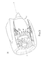
Figure 3 illustrates, in accordance with various embodiments, a perspective cutaway view of an aircraft propulsion system having a fan ramp partially formed on an aft end of a fan case; -
Figure 4 illustrates, in accordance with various embodiments, a schematic cross-sectional view of an aircraft propulsion system having a fan ramp partially formed on an aft end of a fan case, wherein the thrust reversing assembly is stowed; and -
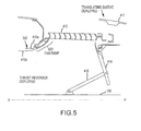
Figure 5 illustrates, in accordance with various embodiments, a schematic cross-sectional view of an aircraft propulsion system having a fan ramp partially formed on an aft end of a fan case, wherein the thrust reversing assembly is deployed. - The detailed description of exemplary embodiments herein makes reference to the accompanying drawings, which show exemplary embodiments by way of illustration. While these exemplary embodiments are described in sufficient detail to enable those skilled in the art to practice the inventions, it should be understood that other embodiments may be realized and that logical, chemical and mechanical changes may be made without departing from the spirit and scope of the inventions. Furthermore, any reference to singular includes plural embodiments, and any reference to more than one component or step may include a singular embodiment or step. Also, any reference to attached, fixed, connected or the like may include permanent, removable, temporary, partial, full and/or any other possible attachment option. Additionally, any reference to without contact (or similar phrases) may also include reduced contact or minimal contact.
- As used herein, "aft" refers to the direction associated with the tail (e.g., the back end) of an aircraft, or generally, to the direction of exhaust of the gas turbine. As used herein, "forward" refers to the directed associated with the nose (e.g., the front end) of an aircraft, or generally, to the direction of flight or motion. For example, with reference to
Figure 1 , point A is forward of point A' along axis A-A'. - With reference now to
Figure 1A , a partial cross-section of a jet aircraftpropulsion system nacelle 100 is shown. Thenacelle 100 may extend from forward to aft along the axis A-A'. In flight, air from point A may flow around and/or through thepropulsion system 100 in the direction from point A to point A'. - The
nacelle 100 may generally function to package a gas turbine engine and a fan orturbofan 102, and may guide air around the external portion of thenacelle 100 and internally through thenacelle 100 to define thebypass duct 104. - The
nacelle 100 may include anair inlet 106 through which air may enter thenacelle 100. Some portion of airflow may enter the gas turbine engine, and some portion of airflow may flow through thebypass air duct 104. An inner fixed structure ("IFS") 108 may define an inner airflow surface of thebypass air duct 104 and may be disposed coaxially about the gas turbine engine. The gas turbine engine may burn a hydrocarbon fuel in the presence of compressed air to generate exhaust gas. The exhaust gas may drive a turbine, which may, through a shaft, drive theturbofan 102 at the forward portion of thenacelle 100. Theturbofan 102 may rotate to generate bypass fan airflow in abypass air duct 104. - The
nacelle 100 may further comprise a thrust reversing assembly or a thrust reverser. The thrust reversing assembly may comprise a plurality of thrust reversing components, including, for example, a translatingsleeve 110, acascade 112, one ormore blocker doors 116, and/or one or moredrag links 118. Theblocker door 116 may be coupled to the IFS 108 by thedrag link 118. - Generally, with reference to
Figure 1B , during a thrust reversing operation, theblocker door 116 may deploy from a stowed position to block bypass air flowing through thebypass air duct 104. In particular, thetranslating sleeve 110 may translate aft. As the translatingsleeve 110 moves aft, theblocker door 116, which is coupled to the translatingsleeve 110, may translate after as well. Thedrag link 118 may, however, remain fixed to theIFS 108. - Thus, as the
blocker door 116 translates aft with the translatingsleeve 110, thedrag link 118 may pull theblocker door 116 radially inward into a deployed position. As shown, in a deployed position, theblocker door 116 may project radially within thebypass duct 104 to block at least a portion of the fan air flow in thebypass air duct 104. - As air enters the
bypass air duct 104, a curved structure or "fan ramp" 105 may channel air into thecascade 112. Theblocker door 116 may, in addition, redirect fan air into thecascade 112. Thecascade 112 may therefore channel fan air out of thenacelle 100 in a forward direction to generate reverse thrust. - With reference to
Figure 2 , a portion of aprior art nacelle 100 is shown in greater detail. Specifically, a priorart fan case 202,fan ramp 105, andblocker door 116 are shown. In general, thefan case 202 may comprise an annular or cylindrical structure that surrounds the engine core. Thefan case 202 may therefore comprise an inner surface and an outer surface. Moreover, the inner surface may comprise a constant (or substantially constant) radius. Thus, the inner surface of thefan case 202 may not include a curvature (or only a slight curvature, such as less than 5 degrees). - As discussed above, fan case design has conventionally held that a fan case should conform to a perfect aerodynamic (or "loft") surface of the
fan duct 104. A perfect loft surface is illustrated inFigure 2 and is identified by thereference number 204. Aperfect loft surface 204 may comprise an ideal aerodynamic surface over which air would flow to achieve maximum efficiency. However, to move air from the duct through the cascades in response to thrust reverser deployment,fan ramp 105 deviates from theperfect loft surface 204. A fan ramp may be defined as beginning at the forward most point at which a surface of a duct deviates from theperfect loft surface 204. For example, a fan case that followsideal loft surface 204 and a radial departure from theideal loft surface 204 at thefan ramp 105 may define, in the prior art, the forward most portion of afan ramp 105. - Now, as shown with reference to
Figures 3-5 , a perspective view of a partiallycutaway nacelle 300 is shown. Thenacelle 300 may include acascade 412, ablocker door 416, adrag link 418, anIFS 108, and/or a fancowl translating sleeve 411. In addition, unlike thenacelle 100 described above, thenacelle 300 may comprise afan case 302 having a curvature. More particularly, thefan case 302 may comprise a radiallyinterior surface 410b and aradially exterior surface 410a. The radiallyinterior surface 410b of thefan case 302 may deviate (or begin to curve radially outward) from anideal loft surface 406 that begins forward of anaft end 408 of thefan case 302. In this manner, thefan case 302 may contribute to the curvature of afan ramp 502. Stated another way, in various embodiments, a fan ramp's forward most point is the forward most point where a duct deviates from theideal loft surface 406. As shown inFIG. 4 , radiallyinterior surface 410b offan case 302 deviates from theideal loft surface 406 and, accordingly, radiallyinterior surface 410b offan case 302 comprises a portion of a fan ramp. - Again, as shown in greater detail with respect to
Figures 4 and5 (showing athrust reversing assembly 400 in a stowed and deployed configuration, respectively), thefan case 302 may terminate at anaft end 408 that is aft of a deviation of the radiallyinterior surface 410b of thefan case 302 from theperfect loft surface 406. Thus, the fan cancase 302 may contribute to the curvature of thefan ramp 502. In other words, thefan ramp 502 may be shared with thefan case 302. - As a result of the
fan ramp 502 sharing described above, a variety of system components (e.g., a torque box, thecascade 412, and the like) may be allowed to occupy a more forward portion of the nacelle 300 (in comparison to the nacelle 100). In addition, as thefan ramp 502 occupies a more forward position than is conventional, a torque box may also occupy a more forward position than is conventional and/or its dimensions (in particular its width) reduced during construction. The aerodynamic geometry of thenacelle 300 may be improved over that associated with thenacelle 100 as well. For example, thenacelle 300 may sweep more steeply aft than thenacelle 100. - Benefits, other advantages, and solutions to problems have been described herein with regard to specific embodiments. Furthermore, the connecting lines shown in the various figures contained herein are intended to represent exemplary functional relationships and/or physical couplings between the various elements. It should be noted that many alternative or additional functional relationships or physical connections may be present in a practical system. However, the benefits, advantages, solutions to problems, and any elements that may cause any benefit, advantage, or solution to occur or become more pronounced are not to be construed as critical, required, or essential features or elements of the inventions. The scope of the inventions is accordingly to be limited by nothing other than the appended claims, in which reference to an element in the singular is not intended to mean "one and only one" unless explicitly so stated, but rather "one or more." Different cross-hatching is used throughout the figures to denote different parts but not necessarily to denote the same or different materials. Systems, methods and apparatus are provided herein. In the detailed description herein, references to "one embodiment", "an embodiment", "various embodiments", etc., indicate that the embodiment described may include a particular feature, structure, or characteristic, but every embodiment may not necessarily include the particular feature, structure, or characteristic. Moreover, such phrases are not necessarily referring to the same embodiment. Further, when a particular feature, structure, or characteristic is described in connection with an embodiment, it is submitted that it is within the knowledge of one skilled in the art to affect such feature, structure, or characteristic in connection with other embodiments whether or not explicitly described. After reading the description, it will be apparent to one skilled in the relevant art(s) how to implement the disclosure in alternative embodiments.
- Furthermore, no element, component, or method step in the present disclosure is intended to be dedicated to the public regardless of whether the element, component, or method step is explicitly recited in the claims. No claim element herein is to be construed under the provisions of 35 U.S.C. 112(f) unless the element is expressly recited using the phrase "means for." As used herein, the terms "comprises," "comprising," or any other variation thereof, are intended to cover a non-exclusive inclusion, such that a process, method, article, or apparatus that comprises a list of elements does not include only those elements but may include other elements not expressly listed or inherent to such process, method, article, or apparatus.
Claims (15)
- An aircraft propulsion system comprising:an annular fan case (202; 302) that houses a fan (102), the fan case (202; 302) comprising a radially interior surface (410b) and a radially exterior surface (410a), the radially interior surface (410b) of the fan case (202; 302) deviating radially outward from an ideal loft surface (406) that begins forward of an aft end (408) of the fan case (202; 302) such that the fan case (202; 302) comprises a portion of a fan ramp (105; 502).
- The aircraft propulsion system of claim 1, wherein the fan ramp aerodynamically guides air in a bypass air duct to a forward portion of a cascade.
- The aircraft propulsion system of claim 1 or 2, wherein the ideal loft surface (406) is defined as a line extending between a portion of the fan case (202; 302) that is forward of an axial end of the fan case (105; 502) and a forward portion of a blocker door (116; 416).
- The aircraft propulsion system of claim 1, 2 or 3, further comprising a thrust reverser assembly (400) that includes a or the cascade (112; 412) and a torque box at least partially surrounding the cascade (112; 412) and supporting the cascade (112; 412).
- The aircraft propulsion system of any preceding claim, further comprising a gas turbine engine.
- The aircraft propulsion system of any preceding claim, wherein a or the bypass duct (104) is formed around a or the gas turbine engine.
- The aircraft propulsion system of any preceding claim, further comprising a fan (102) that drives air through a or the bypass duct (104).
- An aircraft propulsion system comprising:a gas turbine engine;a bypass air duct (104) formed around the engine;a fan (102) coupled to the engine that drives bypass air through the bypass air duct (104);an annular fan case (202; 302) located radially external of the fan (102) with a radially interior surface (410b) defining at least in part the bypass duct (104);a thrust reverser assembly (400) including a cascade (112; 412) and torque box at least partially surrounding the cascade (112; 412) and supporting it; anda fan ramp (105; 502) including a continuously curved aerodynamic surface extending from a point forward of an aft end (408) of the interior surface of the fan case (202; 302) to the forward portion of the cascade (112; 412) and which aerodynamically guides air in the bypass duct (104) from the fan case (202; 302) to the cascade (112; 412) forward portion, and, wherein the fan ramp (105; 502) is formed at least in part on the fan case (202; 302).
- The aircraft propulsion system of claim 8, wherein the radially interior surface (410b) of the fan case (202; 302) deviates radially outward from an ideal loft surface (406) that begins forward of an aft end (408) of the fan case (202; 302) such that the fan case (202; 302) comprises a portion of the fan ramp (105; 502).
- The aircraft propulsion system of claim 9, wherein the ideal loft surface (406) is defined, in cross-section, as a line extending between a portion of the fan case (202; 302) that is forward of an axial end of the fan case (202; 302) and a forward portion of a blocker door (116; 416).
- The aircraft propulsion system of any preceding claim, wherein the radially interior surface (410b) of the fan case (202; 302) is curved.
- The aircraft propulsion system of any preceding claim, wherein the radially interior surface (410b) of the fan case (202; 302) curves radially outward to form a portion of the fan ramp (105; 502).
- The aircraft propulsion system of any preceding claim, wherein a translating sleeve (110; 411) comprising a portion of a or the thrust reversing assembly (400) is shifted aft to expose the fan ramp (105; 502) to a or the bypass air duct (104).
- The aircraft propulsion system of any preceding claim, further comprising an inner fixed structure (108) formed about a or the gas turbine engine and defining at least in part the bypass duct (104).
- The aircraft propulsion system of any preceding claim, wherein a or the translating sleeve (110; 411) is shifted forward to cover the fan ramp (105; 502).
Applications Claiming Priority (1)
| Application Number | Priority Date | Filing Date | Title |
|---|---|---|---|
| US14/058,118 US20150107222A1 (en) | 2013-10-18 | 2013-10-18 | Thrust reverser fan ramp partially formed on aft end of fan case |
Publications (1)
| Publication Number | Publication Date |
|---|---|
| EP2863040A1 true EP2863040A1 (en) | 2015-04-22 |
Family
ID=51870798
Family Applications (1)
| Application Number | Title | Priority Date | Filing Date |
|---|---|---|---|
| EP20140188954 Withdrawn EP2863040A1 (en) | 2013-10-18 | 2014-10-15 | Thrust reverser fan ramp partially formed on aft end of fan case |
Country Status (3)
| Country | Link |
|---|---|
| US (1) | US20150107222A1 (en) |
| EP (1) | EP2863040A1 (en) |
| CN (1) | CN104554740A (en) |
Cited By (1)
| Publication number | Priority date | Publication date | Assignee | Title |
|---|---|---|---|---|
| US20210284350A1 (en) * | 2020-02-24 | 2021-09-16 | Airbus Operations Sas | Aircraft nacelle having a fan ramp with articulated flaps |
Families Citing this family (7)
| Publication number | Priority date | Publication date | Assignee | Title |
|---|---|---|---|---|
| US10428763B2 (en) | 2016-04-01 | 2019-10-01 | Rohr, Inc. | Controlling a relative position at an interface between translating structures of an aircraft nacelle |
| US11046034B2 (en) | 2016-04-18 | 2021-06-29 | Rohr, Inc. | Manufacturing a fiber-reinforced composite component using mandrels |
| US10563614B2 (en) | 2016-08-17 | 2020-02-18 | Honeywell International Inc. | Composite translating cowl assembly for a thrust reverser system |
| US10525636B2 (en) | 2017-06-19 | 2020-01-07 | Rohr, Inc. | Process for forming a fiber-reinforced composite structure |
| FR3107568B1 (en) * | 2020-02-26 | 2022-02-18 | Safran Nacelles | FORWARD FRAME AND DEVIATION GRID OF AN AIRCRAFT NACELLE THRUST REVERSER |
| CN114620238A (en) * | 2020-12-12 | 2022-06-14 | 罗尔公司 | Multi-lobe type external fillet slope |
| FR3135757B1 (en) * | 2022-05-20 | 2026-05-08 | Safran Nacelles | Thrust reverser including a simplified deployment sealing membrane |
Citations (7)
| Publication number | Priority date | Publication date | Assignee | Title |
|---|---|---|---|---|
| GB2045179A (en) * | 1979-03-30 | 1980-10-29 | Gen Electric | Thrust reverser for a long duct fan engine |
| US4527391A (en) * | 1982-09-30 | 1985-07-09 | United Technologies Corporation | Thrust reverser |
| US4894985A (en) * | 1987-07-29 | 1990-01-23 | Societe Anonyme Dite: Hispano Suiza | Thrust reverser with movable deflector |
| EP1852595A2 (en) * | 2006-05-06 | 2007-11-07 | Rolls-Royce plc | Aeroengine thrust reverser |
| FR2965589A1 (en) * | 2010-10-04 | 2012-04-06 | Aircelle Sa | PUSH INVERTER |
| US20130161414A1 (en) * | 2007-08-08 | 2013-06-27 | Goodrich Actuation Systems Limited | Actuation system for a translating variable area fan nozzle |
| US20130255225A1 (en) * | 2012-03-27 | 2013-10-03 | Michael N. Charron | Gas turbine engine thrust reverser system |
Family Cites Families (7)
| Publication number | Priority date | Publication date | Assignee | Title |
|---|---|---|---|---|
| US4722821A (en) * | 1983-12-30 | 1988-02-02 | The Boeing Company | Method of making a cascade basket for a thrust reverser |
| US4998409A (en) * | 1989-09-25 | 1991-03-12 | Rohr Industries, Inc. | Thrust reverser torque ring |
| US5575147A (en) * | 1994-12-22 | 1996-11-19 | United Technologies Corporation | Compact thrust reverser |
| US6557799B1 (en) * | 2001-11-09 | 2003-05-06 | The Boeing Company | Acoustic treated thrust reverser bullnose fairing assembly |
| FR2900980B1 (en) * | 2006-05-10 | 2011-08-19 | Aircelle Sa | NACELLE FOR DOUBLE FLOW TURBOREACTOR WITH HIGH DILUTION RATE |
| US8109466B2 (en) * | 2008-06-23 | 2012-02-07 | Rohr, Inc. | Thrust reverser cascade assembly and AFT cascade ring with flow deflector portion |
| EP2278146B1 (en) * | 2009-06-16 | 2013-07-24 | Rohr, Inc. | Actuation system for a translating variable area fan nozzle |
-
2013
- 2013-10-18 US US14/058,118 patent/US20150107222A1/en not_active Abandoned
-
2014
- 2014-09-30 CN CN201410516282.0A patent/CN104554740A/en active Pending
- 2014-10-15 EP EP20140188954 patent/EP2863040A1/en not_active Withdrawn
Patent Citations (7)
| Publication number | Priority date | Publication date | Assignee | Title |
|---|---|---|---|---|
| GB2045179A (en) * | 1979-03-30 | 1980-10-29 | Gen Electric | Thrust reverser for a long duct fan engine |
| US4527391A (en) * | 1982-09-30 | 1985-07-09 | United Technologies Corporation | Thrust reverser |
| US4894985A (en) * | 1987-07-29 | 1990-01-23 | Societe Anonyme Dite: Hispano Suiza | Thrust reverser with movable deflector |
| EP1852595A2 (en) * | 2006-05-06 | 2007-11-07 | Rolls-Royce plc | Aeroengine thrust reverser |
| US20130161414A1 (en) * | 2007-08-08 | 2013-06-27 | Goodrich Actuation Systems Limited | Actuation system for a translating variable area fan nozzle |
| FR2965589A1 (en) * | 2010-10-04 | 2012-04-06 | Aircelle Sa | PUSH INVERTER |
| US20130255225A1 (en) * | 2012-03-27 | 2013-10-03 | Michael N. Charron | Gas turbine engine thrust reverser system |
Cited By (2)
| Publication number | Priority date | Publication date | Assignee | Title |
|---|---|---|---|---|
| US20210284350A1 (en) * | 2020-02-24 | 2021-09-16 | Airbus Operations Sas | Aircraft nacelle having a fan ramp with articulated flaps |
| US11577849B2 (en) * | 2020-02-24 | 2023-02-14 | Airbus Operations Sas | Aircraft nacelle having a fan ramp with articulated flaps |
Also Published As
| Publication number | Publication date |
|---|---|
| US20150107222A1 (en) | 2015-04-23 |
| CN104554740A (en) | 2015-04-29 |
Similar Documents
| Publication | Publication Date | Title |
|---|---|---|
| EP2937551B1 (en) | Nacelle comprising a thrust reverser | |
| US20150107222A1 (en) | Thrust reverser fan ramp partially formed on aft end of fan case | |
| US10563615B2 (en) | Gas turbine engine with thrust reverser assembly and method of operating | |
| JP5572285B2 (en) | Turbofan engine cowl assembly and thrust reverser assembly | |
| US10184426B2 (en) | Thrust reverser with forward positioned blocker doors | |
| EP4180648B1 (en) | Hidden link system blocker door | |
| US9410501B2 (en) | Translating sleeve actuation system and apparatus | |
| US10502161B2 (en) | Cascade system and apparatus | |
| EP2951090B1 (en) | Cowl with pressure driven latch | |
| US11548652B2 (en) | Nacelle | |
| EP3587783B1 (en) | Collapsible drag link | |
| US20170283081A1 (en) | Securing a translating fanlet for an aircraft propulsion system nacelle | |
| US9574519B2 (en) | Multi surface blocker door system and apparatus | |
| US9869275B2 (en) | Single actuator variable area fan nozzle system and method | |
| US20240401546A1 (en) | Turbine engine having a thrust reverser system | |
| US9650992B2 (en) | Core cowl thrust reverser system and apparatus | |
| EP3434596B1 (en) | Nacelle | |
| US9856742B2 (en) | Sealing system for variable area fan nozzle | |
| EP2876288B1 (en) | Aircraft propulsion system fan case comprising thrust reversing assembly | |
| US20190218999A1 (en) | Thrust reverser pivot door with extended forward edge |
Legal Events
| Date | Code | Title | Description |
|---|---|---|---|
| PUAI | Public reference made under article 153(3) epc to a published international application that has entered the european phase |
Free format text: ORIGINAL CODE: 0009012 |
|
| 17P | Request for examination filed |
Effective date: 20141015 |
|
| AK | Designated contracting states |
Kind code of ref document: A1 Designated state(s): AL AT BE BG CH CY CZ DE DK EE ES FI FR GB GR HR HU IE IS IT LI LT LU LV MC MK MT NL NO PL PT RO RS SE SI SK SM TR |
|
| AX | Request for extension of the european patent |
Extension state: BA ME |
|
| STAA | Information on the status of an ep patent application or granted ep patent |
Free format text: STATUS: THE APPLICATION IS DEEMED TO BE WITHDRAWN |
|
| 18D | Application deemed to be withdrawn |
Effective date: 20151023 |