EP2862799A1 - Retention assembly for a propeller blade - Google Patents
Retention assembly for a propeller blade Download PDFInfo
- Publication number
- EP2862799A1 EP2862799A1 EP20140188983 EP14188983A EP2862799A1 EP 2862799 A1 EP2862799 A1 EP 2862799A1 EP 20140188983 EP20140188983 EP 20140188983 EP 14188983 A EP14188983 A EP 14188983A EP 2862799 A1 EP2862799 A1 EP 2862799A1
- Authority
- EP
- European Patent Office
- Prior art keywords
- propeller blade
- retention assembly
- assembly
- inch
- blade
- Prior art date
- Legal status (The legal status is an assumption and is not a legal conclusion. Google has not performed a legal analysis and makes no representation as to the accuracy of the status listed.)
- Granted
Links
Images

Classifications
-
- F—MECHANICAL ENGINEERING; LIGHTING; HEATING; WEAPONS; BLASTING
- F01—MACHINES OR ENGINES IN GENERAL; ENGINE PLANTS IN GENERAL; STEAM ENGINES
- F01D—NON-POSITIVE DISPLACEMENT MACHINES OR ENGINES, e.g. STEAM TURBINES
- F01D5/00—Blades; Blade-carrying members; Heating, heat-insulating, cooling or antivibration means on the blades or the members
- F01D5/12—Blades
- F01D5/14—Form or construction
-
- B—PERFORMING OPERATIONS; TRANSPORTING
- B64—AIRCRAFT; AVIATION; COSMONAUTICS
- B64C—AEROPLANES; HELICOPTERS
- B64C11/00—Propellers, e.g. of ducted type; Features common to propellers and rotors for rotorcraft
- B64C11/02—Hub construction
- B64C11/04—Blade mountings
- B64C11/06—Blade mountings for variable-pitch blades
-
- B—PERFORMING OPERATIONS; TRANSPORTING
- B64—AIRCRAFT; AVIATION; COSMONAUTICS
- B64C—AEROPLANES; HELICOPTERS
- B64C11/00—Propellers, e.g. of ducted type; Features common to propellers and rotors for rotorcraft
- B64C11/16—Blades
- B64C11/20—Constructional features
- B64C11/26—Fabricated blades
Definitions
- the subject matter disclosed herein relates generally to propeller systems and blades and, more particularly, to a lightweight propeller blade assembly with an improved retention capacity for lower centrifugal loads.
- Modem propeller blades typically incorporate composite materials that reduce weight and enhance performance.
- the composite blades typically include a blade portion and a root portion which extends into a hub arm of the hub of a propeller system and which is secured to and rotatable relative to the hub arm via a retention assembly.
- a challenge with lightweight composite blades is that a bending moment (BM) capacity of the retention assembly to the hub arm is often reduced due to a lower centrifugal load (CL) of the blade.
- a typical lightweight propeller blade using a type of arrangement to address BM includes the system shown in U.S. Pat. No. 6,676,080 .
- the bearing races are sized for bearings that can withstand bending moments, but the interface between the composite blade and outer ring bearing race may become unloaded due to insufficient centrifugal loading. This is an undesirable condition which may reduce the life of the composite blade portion and/or outer ring.
- a retention assembly for a propeller blade includes an inner ring that is conformally shaped to a bore of an annular loop, the annular loop being associated with a root portion of the propeller blade; a base that is configured to be immediately adjacent the annular loop; an outer ring that includes an extended tapered portion which decreases in radial thickness from an inboard end to an outboard end; and an adhesive that adhesively connects complementary surfaces of the outer ring and the annular loop.
- a propeller blade assembly includes a propeller blade including a blade portion and a root portion; and a retention assembly configured to be attached to the propeller blade.
- the retention assembly further includes an inner ring that is conformally shaped to a bore of an annular loop, the annular loop being associated with the root portion; a base that is configured to be immediately adjacent the annular loop; an outer ring that includes an extended tapered portion which decreases in radial thickness from an inboard end to an outboard end; and an adhesive that adhesively connects complementary surfaces of the outer ring and the annular loop.
- FIG. 1 is a plan view of an aircraft 10 having a plurality of lightweight propeller blade assemblies 22 with an improved retention capacity according to an embodiment of the invention.
- the aircraft 10 includes a fuselage 12, a cockpit 14, and a tail 16. Attached to the fuselage 12 are left and right wings 18a, 18b respectively. Each wing 18a, 18b incorporates a respective propeller 20a, 20b that is aligned on respective axes A, B.
- Each propeller 20a, 20b includes a plurality of propeller blade assemblies 22 that are driven for rotation by respective gas turbine engines 24a, 24b.
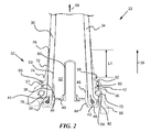
- the propeller blade assembly 22 includes a propeller blade 30 that is received and secured to a retention assembly 32.
- the propeller blade 30 includes a blade portion 34 that terminates into a root portion 36.
- the propeller blade 30 is generally cylindrical in shape at root portion 36 and transitions to an airfoil shape that thins and flattens toward a tip (not shown) which is directionally opposite root portion 36 in a direction of arrow 39 (i.e., from inboard/hub end to an outboard/tip end of the propeller blade 30).
- propeller blade 30 may also spiral or twist toward the tip (not shown) in a known manner according to the type of propeller blade that is used.
- propeller blade 30 including blade portion 34 and root portion 36 may be constructed of one or more layers of unidirectional and/or woven glass fibers, and one or more layers of unidirectional and/or woven graphite fibers that are embedded in a suitable resin material as is well-known to a person of ordinary skill in the art.
- the root portion 36 is configured to attach to a retention assembly 32. It is to be appreciated that the retention assembly 32 is configured to attach to the propeller blade 30 and provide an improved retention capacity for high blade moments and lower centrifugal loads, as will be described in greater detail below.
- the root portion 36 includes an annular loop 38 that forms a teardrop-shaped bore 41.
- Retention assembly 32 includes an inner ring 40, an extended outer ring 42, and a generally cup-shaped base 44.
- rings 40, 42 may be machined from high strength stainless steel, although aluminum, titanium or other suitable metals or composites may be used.
- the base 44 may be machined from aluminum material, but may alternatively be constructed of other materials, such as steel, composites, or the like.
- inner ring 40 is conformally shaped to the bore 41 (i.e., inner ring 40 may include a tear-drop shaped cross-section) and is located inside the bore 41.
- the base 44 is positioned immediately adjacent annular loop 38 and includes a lower end 46, a wall 48, and a lateral portion 49.
- the wall 48 extends upwardly from lower end 46 into a hollow root cavity 52 and is in frictional engagement with an inner surface 50 of root portion 36.
- lateral portion 49 resides inside the hollow root cavity 52.
- the annular loop 38 and inner ring 40 are sandwiched between base 44 and extended outer ring 42.
- a balance tube 80 extends through a central opening defined by lateral portion 49 in base 44. The balance tube 80 and lateral portion 49 close hollow root cavity of root portion 36 to prevent intrusion of oil and/or moisture into the hollow root cavity 52 which may otherwise damage propeller blade 30.
- the extended outer ring 42 is generally annular in shape and includes, moving inboard to outboard, a bearing race interface 54, a bearing race groove 56, a lower annular groove 57, a plurality of flanges 60, 62 that are located between bearing race groove 56, and an upper annular groove 58.
- the bearing race interface 54 has a radially internal surface that is complementary to radially outer curved surface 78 of annular loop 38.
- the bearing race groove 56 is a bearing race that receives a bearing assembly 70 such as, for example, an angular contact ball bearing assembly, tapered roller bearing assembly, deep groove thrust or roller bearing assembly, two-piece bearing race assemblies, or the like.
- a single bearing race groove 56 is shown and described, in an embodiment, two or more bearing race grooves substantially similar may also be provided for use with a propeller hub 66 that can use multiple row bearing assemblies.
- the flanges 60, 62 cooperatively define a lower annular groove 57 that is adapted to receive an O-ring 68 while an upper annular groove 58 is adapted to receive a locking ring (not shown) for holding propeller blade assembly 22 against movement into the propeller hub 66 when not in use.
- the flanges 60, 62 bear against a retaining surface 64 of a propeller hub 66 to contain the O-ring 68.
- the bearing race groove 56 cooperates with the hub race groove 82 to contain the bearing assembly 70 and prevent separation of propeller blade assembly 22 from propeller hub 66 when high outward centrifugal force applied in a direction of arrow 69 during rotation of propeller hub 66.
- upper annular groove 58 terminates into a tapered portion 72.
- the tapered portion 72 has a length L1 that gets progressively thinner radially from inboard end 74 to an outboard end 76.
- tapered portion 72 has an internal taper along an internal surface of portion 72 (to be conformal to the outer surface of blade portion 34) and an external taper along an outer surface of portion 72, as illustrated in the figure.
- thickness of tapered portion 72 from inboard end 74 to outboard end 76 is reduced between about 0.05 inch (0.127 centimeter) to about 0.10 inch (0.254 centimeter) for every inch (2.54 centimeter) of length of tapered portion 72.
- thickness at outboard end 76 is between about 0.005 inch (0.013 centimeter) to about 0.035 inch (0.089 centimeter).
- length L1 is about 0.5 inch (1.270 centimeter) to about 2 inch (5.080 centimeter).
- an adhesive is utilized along complementary mutual interfaces of extended outer ring 42 and root portion 36 in order to adhesively connect the mutual interfaces (or complementary surfaces). As illustrated in FIG. 2 , mutual interfaces include, on propeller blade 30, an outer curved surface 78 of annular loop 38 moving upwards to blade portion 34 which contacts, on retention assembly 32, a radially internal surface of bearing race interface 54 to outboard end 76 of outer ring 42.
- the adhesive could be a structural adhesive such as an epoxy and/or a compliant adhesive such as polyurethane, polysulfide or RTV silicone.
- Hysol® EA 9346.5 epoxy paste adhesive manufactured by the Henkel Corporation may be used as the structural adhesive.
- the retention capacity of an interface between the composite blade and outer ring bearing race may become unloaded due to insufficient centrifugal loading which may reduce the life of the blade portion and/or the outer ring of the propeller blade.
- benefits of the present invention with a use of the outer ring 42 and an adhesive to coupled mutual interfaces is an improved retention capacity for use with lightweight composite propeller blades.
- the retention capacity is facilitated with a retention assembly 32 having an added length of outer ring 42 and an adhesive that couples mutual interfaces of the propeller blade 30.
- Using the additional length for outer ring 42 and the adhesive increases a bending moment capacity over prior art propeller blades because it prevents the lightweight propeller blade 30 from separating at a bearing race interface 54 of outer ring 42.
- an adhesive layer between the contact surface of outer ring 42 and a root portion 36 of propeller blade 30 provides a shear path to direct the bending loads to the bearings 70 thereby preventing unloading of the propeller blade 30 at the bearing race interface 54.
Landscapes
- Engineering & Computer Science (AREA)
- Aviation & Aerospace Engineering (AREA)
- Mechanical Engineering (AREA)
- General Engineering & Computer Science (AREA)
- Structures Of Non-Positive Displacement Pumps (AREA)
Abstract
Description
- The subject matter disclosed herein relates generally to propeller systems and blades and, more particularly, to a lightweight propeller blade assembly with an improved retention capacity for lower centrifugal loads.
- Modem propeller blades typically incorporate composite materials that reduce weight and enhance performance. The composite blades typically include a blade portion and a root portion which extends into a hub arm of the hub of a propeller system and which is secured to and rotatable relative to the hub arm via a retention assembly. A challenge with lightweight composite blades is that a bending moment (BM) capacity of the retention assembly to the hub arm is often reduced due to a lower centrifugal load (CL) of the blade. A typical lightweight propeller blade using a type of arrangement to address BM includes the system shown in
U.S. Pat. No. 6,676,080 . As can be seen from the drawings of this patent, the bearing races are sized for bearings that can withstand bending moments, but the interface between the composite blade and outer ring bearing race may become unloaded due to insufficient centrifugal loading. This is an undesirable condition which may reduce the life of the composite blade portion and/or outer ring. - Thus, there is a need for a lightweight propeller blade with an improved retention capacity that can withstand high bending moments at lower centrifugal loading.
- According to an aspect of the invention, a retention assembly for a propeller blade includes an inner ring that is conformally shaped to a bore of an annular loop, the annular loop being associated with a root portion of the propeller blade; a base that is configured to be immediately adjacent the annular loop; an outer ring that includes an extended tapered portion which decreases in radial thickness from an inboard end to an outboard end; and an adhesive that adhesively connects complementary surfaces of the outer ring and the annular loop.
- According to another aspect of the invention, a propeller blade assembly includes a propeller blade including a blade portion and a root portion; and a retention assembly configured to be attached to the propeller blade. The retention assembly further includes an inner ring that is conformally shaped to a bore of an annular loop, the annular loop being associated with the root portion; a base that is configured to be immediately adjacent the annular loop; an outer ring that includes an extended tapered portion which decreases in radial thickness from an inboard end to an outboard end; and an adhesive that adhesively connects complementary surfaces of the outer ring and the annular loop.
- Other aspects, features, and techniques of the invention will become more apparent from the following description taken in conjunction with the drawings.
- The subject matter, which is regarded as the invention, is particularly pointed out and distinctly claimed in the claims at the conclusion of the specification. The foregoing and other features, and advantages of the invention are apparent from the following detailed description taken in conjunction with the accompanying drawings in which like elements are numbered alike in the several FIGURES:
-
FIG. 1 is a plan view of an aircraft according to an embodiment of the invention; and -
FIG. 2 is a cross-sectional view of a propeller blade assembly ofFIG. 1 according to an embodiment of the invention. - Referring to the drawings,
FIG. 1 is a plan view of anaircraft 10 having a plurality of lightweight propeller blade assemblies 22 with an improved retention capacity according to an embodiment of the invention. Theaircraft 10 includes afuselage 12, acockpit 14, and atail 16. Attached to thefuselage 12 are left andright wings wing respective propeller propeller propeller blade assemblies 22 that are driven for rotation by respectivegas turbine engines specific aircraft 10 is illustrated and described herein, other propeller driven aircrafts are within the scope of the invention. - Referring to
FIG. 2 , a cross-section view of a lightweightpropeller blade assembly 22 that has an improved retention capacity is illustrated according to an embodiment of the invention. Thepropeller blade assembly 22 includes apropeller blade 30 that is received and secured to aretention assembly 32. Thepropeller blade 30 includes ablade portion 34 that terminates into aroot portion 36. Thepropeller blade 30 is generally cylindrical in shape atroot portion 36 and transitions to an airfoil shape that thins and flattens toward a tip (not shown) which is directionallyopposite root portion 36 in a direction of arrow 39 (i.e., from inboard/hub end to an outboard/tip end of the propeller blade 30). In embodiments, the shape ofpropeller blade 30 may also spiral or twist toward the tip (not shown) in a known manner according to the type of propeller blade that is used. In embodiments,propeller blade 30 includingblade portion 34 androot portion 36 may be constructed of one or more layers of unidirectional and/or woven glass fibers, and one or more layers of unidirectional and/or woven graphite fibers that are embedded in a suitable resin material as is well-known to a person of ordinary skill in the art. Theroot portion 36 is configured to attach to aretention assembly 32. It is to be appreciated that theretention assembly 32 is configured to attach to thepropeller blade 30 and provide an improved retention capacity for high blade moments and lower centrifugal loads, as will be described in greater detail below. - The
root portion 36 includes anannular loop 38 that forms a teardrop-shaped bore 41.Retention assembly 32 includes aninner ring 40, an extendedouter ring 42, and a generally cup-shaped base 44. In embodiments,rings base 44 may be machined from aluminum material, but may alternatively be constructed of other materials, such as steel, composites, or the like. Also,inner ring 40 is conformally shaped to the bore 41 (i.e.,inner ring 40 may include a tear-drop shaped cross-section) and is located inside thebore 41. Thebase 44 is positioned immediately adjacentannular loop 38 and includes alower end 46, awall 48, and alateral portion 49. Thewall 48 extends upwardly fromlower end 46 into ahollow root cavity 52 and is in frictional engagement with aninner surface 50 ofroot portion 36. Also,lateral portion 49 resides inside thehollow root cavity 52. Theannular loop 38 andinner ring 40 are sandwiched betweenbase 44 and extendedouter ring 42. Abalance tube 80 extends through a central opening defined bylateral portion 49 inbase 44. Thebalance tube 80 andlateral portion 49 close hollow root cavity ofroot portion 36 to prevent intrusion of oil and/or moisture into thehollow root cavity 52 which may otherwise damagepropeller blade 30. - The extended
outer ring 42 is generally annular in shape and includes, moving inboard to outboard, abearing race interface 54, abearing race groove 56, a lowerannular groove 57, a plurality offlanges race groove 56, and an upperannular groove 58. Thebearing race interface 54 has a radially internal surface that is complementary to radially outercurved surface 78 ofannular loop 38. Thebearing race groove 56 is a bearing race that receives abearing assembly 70 such as, for example, an angular contact ball bearing assembly, tapered roller bearing assembly, deep groove thrust or roller bearing assembly, two-piece bearing race assemblies, or the like. Although a single bearingrace groove 56 is shown and described, in an embodiment, two or more bearing race grooves substantially similar may also be provided for use with apropeller hub 66 that can use multiple row bearing assemblies. - The
flanges annular groove 57 that is adapted to receive an O-ring 68 while an upperannular groove 58 is adapted to receive a locking ring (not shown) for holdingpropeller blade assembly 22 against movement into thepropeller hub 66 when not in use. Theflanges retaining surface 64 of apropeller hub 66 to contain the O-ring 68. Thebearing race groove 56 cooperates with thehub race groove 82 to contain thebearing assembly 70 and prevent separation ofpropeller blade assembly 22 frompropeller hub 66 when high outward centrifugal force applied in a direction ofarrow 69 during rotation ofpropeller hub 66. Also, upperannular groove 58 terminates into atapered portion 72. Thetapered portion 72 has a length L1 that gets progressively thinner radially frominboard end 74 to anoutboard end 76. In an embodiment,tapered portion 72 has an internal taper along an internal surface of portion 72 (to be conformal to the outer surface of blade portion 34) and an external taper along an outer surface ofportion 72, as illustrated in the figure. In embodiments, thickness oftapered portion 72 frominboard end 74 tooutboard end 76 is reduced between about 0.05 inch (0.127 centimeter) to about 0.10 inch (0.254 centimeter) for every inch (2.54 centimeter) of length oftapered portion 72. In an embodiment, thickness atoutboard end 76 is between about 0.005 inch (0.013 centimeter) to about 0.035 inch (0.089 centimeter). In an embodiment, length L1 is about 0.5 inch (1.270 centimeter) to about 2 inch (5.080 centimeter). Also, an adhesive is utilized along complementary mutual interfaces of extendedouter ring 42 androot portion 36 in order to adhesively connect the mutual interfaces (or complementary surfaces). As illustrated inFIG. 2 , mutual interfaces include, onpropeller blade 30, an outercurved surface 78 ofannular loop 38 moving upwards toblade portion 34 which contacts, onretention assembly 32, a radially internal surface ofbearing race interface 54 tooutboard end 76 ofouter ring 42. In embodiments, the adhesive could be a structural adhesive such as an epoxy and/or a compliant adhesive such as polyurethane, polysulfide or RTV silicone. In one example, Hysol® EA 9346.5 epoxy paste adhesive manufactured by the Henkel Corporation may be used as the structural adhesive. - In prior art propeller blades, the retention capacity of an interface between the composite blade and outer ring bearing race may become unloaded due to insufficient centrifugal loading which may reduce the life of the blade portion and/or the outer ring of the propeller blade. However, benefits of the present invention with a use of the
outer ring 42 and an adhesive to coupled mutual interfaces is an improved retention capacity for use with lightweight composite propeller blades. The retention capacity is facilitated with aretention assembly 32 having an added length ofouter ring 42 and an adhesive that couples mutual interfaces of thepropeller blade 30. Using the additional length forouter ring 42 and the adhesive increases a bending moment capacity over prior art propeller blades because it prevents thelightweight propeller blade 30 from separating at abearing race interface 54 ofouter ring 42. Additional benefits of using an adhesive is that an adhesive layer between the contact surface ofouter ring 42 and aroot portion 36 ofpropeller blade 30 provides a shear path to direct the bending loads to thebearings 70 thereby preventing unloading of thepropeller blade 30 at thebearing race interface 54. - The terminology used herein is for the purpose of describing particular embodiments only and is not intended to be limiting of the invention. While the description of the present invention has been presented for purposes of illustration and description, it is not intended to be exhaustive or limited to the invention in the form disclosed. For instance, aspects of the invention are not limited to propeller blades for aircraft, and can be used in wind turbines and other systems with rotary elements. Many modifications, variations, alterations, substitutions, or equivalent arrangement not hereto described will be apparent to those of ordinary skill in the art without departing from the scope of the invention. Additionally, while the various embodiment of the invention have been described, it is to be understood that aspects of the invention may include only some of the described embodiments. Accordingly, the invention is not to be seen as limited by the foregoing description, but is only limited by the scope of the appended claims.
Claims (9)
- A retention assembly (32) for a propeller blade (30), comprising:an inner ring (40) that is conformally shaped to a bore (41) of an annular loop (38), the annular loop (38) being associated with a root portion (36) of the propeller blade (30);a base (44) that is configured to be immediately adjacent the annular loop (38);an outer ring (42) that includes an extended tapered portion (72) which decreases in radial thickness from an inboard end (74) to an outboard end (76); andan adhesive that adhesively connects complementary surfaces of the outer ring (42) and the annular loop (38).
- The retention assembly (32) of claim 1, wherein the extended tapered portion (72) decreases in radial thickness of between 0.05 inch (0.127 cm) to 0.10 inch (0.254 cm) for every one inch (2.54 cm) of length from the inboard end (74) to the outboard end (76).
- The retention assembly (32) of claim 1 or 2, wherein a thickness of the outboard end (76) is about 0.005 inch (0.013 cm) to about 0.035 inch (0.089 cm).
- The retention assembly (32) of claim 1, 2 or 3, wherein the outer ring (42) further comprises a bearing race interface (54), a bearing race groove (56), a lower annular groove (57), and an upper annular groove (58).
- The retention assembly (32) of claim 4, wherein a radial outer surface (78) of the annular loop (38) is adhesively connected to a radial inner surface of the bearing race interface (54).
- The retention assembly (32) of claim 4 or 5, further comprising a bearing assembly (70) coupled to the bearing race groove (56).
- The retention assembly (32) of any preceding claim, wherein a length of the extended tapered portion (72) is about 0.5 inch (1.27 cm) to about 2 inch (5.080 cm).
- The retention assembly (32) of any preceding claim, wherein the extended tapered portion (72) includes a first taper on an inner surface and a second taper on an external surface.
- A propeller blade assembly (22), comprising:a propeller blade (30) including a blade portion (34) and a root portion (36); andthe retention assembly (32) of any preceding claim configured to be attached to the propeller blade (30).
Applications Claiming Priority (1)
| Application Number | Priority Date | Filing Date | Title |
|---|---|---|---|
| US14/056,322 US20150110630A1 (en) | 2013-10-17 | 2013-10-17 | Retention assembly for a propeller blade |
Publications (2)
| Publication Number | Publication Date |
|---|---|
| EP2862799A1 true EP2862799A1 (en) | 2015-04-22 |
| EP2862799B1 EP2862799B1 (en) | 2019-01-30 |
Family
ID=51703047
Family Applications (1)
| Application Number | Title | Priority Date | Filing Date |
|---|---|---|---|
| EP14188983.2A Active EP2862799B1 (en) | 2013-10-17 | 2014-10-15 | Retention assembly for a propeller blade |
Country Status (2)
| Country | Link |
|---|---|
| US (1) | US20150110630A1 (en) |
| EP (1) | EP2862799B1 (en) |
Cited By (1)
| Publication number | Priority date | Publication date | Assignee | Title |
|---|---|---|---|---|
| EP4155194A1 (en) | 2021-09-27 | 2023-03-29 | Airbus Helicopters | Rotor blade with a system for retaining and bearing separate forces and rotor equipped with such blades |
Families Citing this family (2)
| Publication number | Priority date | Publication date | Assignee | Title |
|---|---|---|---|---|
| FR3106364B1 (en) * | 2020-01-20 | 2021-12-10 | Safran Aircraft Engines | Blade comprising a composite material structure and associated manufacturing method |
| FR3156753A1 (en) * | 2023-12-13 | 2025-06-20 | Airbus Operations (S.A.S.) | Propeller comprising at least one blade holding system comprising at least one transverse groove |
Citations (4)
| Publication number | Priority date | Publication date | Assignee | Title |
|---|---|---|---|---|
| US3734642A (en) * | 1971-06-29 | 1973-05-22 | United Aircraft Corp | Aerodynamic blade root end attachment |
| GB1567968A (en) * | 1976-12-24 | 1980-05-21 | Huetter U | Stressed skin elements such as wings or rotor blades |
| US6676080B2 (en) | 2000-07-19 | 2004-01-13 | Aero Composites, Inc. | Composite airfoil assembly |
| US20090220344A1 (en) * | 2008-02-28 | 2009-09-03 | Cessna Aircraft Company | Propeller Blade Retention Device |
Family Cites Families (2)
| Publication number | Priority date | Publication date | Assignee | Title |
|---|---|---|---|---|
| US6305905B1 (en) * | 1999-05-05 | 2001-10-23 | United Technologies Corporation | Bolted-on propeller blade |
| FR2958621B1 (en) * | 2010-04-09 | 2012-03-23 | Snecma | NON-CARRIED PROPELLER FOR TURBOMACHINE. |
-
2013
- 2013-10-17 US US14/056,322 patent/US20150110630A1/en not_active Abandoned
-
2014
- 2014-10-15 EP EP14188983.2A patent/EP2862799B1/en active Active
Patent Citations (4)
| Publication number | Priority date | Publication date | Assignee | Title |
|---|---|---|---|---|
| US3734642A (en) * | 1971-06-29 | 1973-05-22 | United Aircraft Corp | Aerodynamic blade root end attachment |
| GB1567968A (en) * | 1976-12-24 | 1980-05-21 | Huetter U | Stressed skin elements such as wings or rotor blades |
| US6676080B2 (en) | 2000-07-19 | 2004-01-13 | Aero Composites, Inc. | Composite airfoil assembly |
| US20090220344A1 (en) * | 2008-02-28 | 2009-09-03 | Cessna Aircraft Company | Propeller Blade Retention Device |
Cited By (3)
| Publication number | Priority date | Publication date | Assignee | Title |
|---|---|---|---|---|
| EP4155194A1 (en) | 2021-09-27 | 2023-03-29 | Airbus Helicopters | Rotor blade with a system for retaining and bearing separate forces and rotor equipped with such blades |
| FR3127472A1 (en) | 2021-09-27 | 2023-03-31 | Airbus Helicopters | rotor blade with a system for retaining and absorbing dissociated forces and rotor equipped with such blades |
| US12116106B2 (en) | 2021-09-27 | 2024-10-15 | Airbus Helicopters | Rotor blade with a system for retention and for take-up of separate stresses and rotor provided with such blades |
Also Published As
| Publication number | Publication date |
|---|---|
| US20150110630A1 (en) | 2015-04-23 |
| EP2862799B1 (en) | 2019-01-30 |
Similar Documents
| Publication | Publication Date | Title |
|---|---|---|
| EP2862800A1 (en) | Retention assembly with a conical interface for a propeller | |
| US6676080B2 (en) | Composite airfoil assembly | |
| US9981736B2 (en) | Folding proprotor blade assembly having integral tang assembly | |
| US6305905B1 (en) | Bolted-on propeller blade | |
| US10717516B2 (en) | Composite propulsor blade support structure and system | |
| US9873507B2 (en) | Rotorcraft elastomeric bearing assembly | |
| US20150093057A1 (en) | Pitch bearing | |
| EP2079634B1 (en) | Propeller blade retention | |
| EP2862799B1 (en) | Retention assembly for a propeller blade | |
| US10173770B2 (en) | Cylindrical elastomeric bearing with tapered shims | |
| CN105377695B (en) | Spherical crown shaped air propeller blade pivot | |
| US20150345551A1 (en) | Rotorcraft bearing with rotation slip joint | |
| US10336446B2 (en) | Directional stiffness bearing sleeve assembly for rotor systems | |
| US20160207620A1 (en) | Rotor hub for rotary wing aircraft | |
| US10960972B2 (en) | Rotorcraft masts having a nonintegral raceway | |
| US10696386B2 (en) | Rigid rotor head with tension torsion (TT) strap retention | |
| US9682773B2 (en) | Systems and methods for blade attachment | |
| EP4223635A1 (en) | Compact propeller blade retention assembly | |
| US12054276B2 (en) | Installation of gear assemblies in aircraft gearboxes | |
| US20150016999A1 (en) | Multi-piece impeller | |
| US10336444B2 (en) | Composite stiffened rigid propeller shaped main rotor hub | |
| US11708156B2 (en) | Friction welded raceways for use in rotorcraft propulsion assemblies | |
| US10703468B2 (en) | Stress reducing holes | |
| US20200385109A1 (en) | Low drag high capacity pitch bearing for rigid rotor aircraft | |
| US20170096213A1 (en) | Structurally efficient pin wrap |
Legal Events
| Date | Code | Title | Description |
|---|---|---|---|
| PUAI | Public reference made under article 153(3) epc to a published international application that has entered the european phase |
Free format text: ORIGINAL CODE: 0009012 |
|
| 17P | Request for examination filed |
Effective date: 20141015 |
|
| AK | Designated contracting states |
Kind code of ref document: A1 Designated state(s): AL AT BE BG CH CY CZ DE DK EE ES FI FR GB GR HR HU IE IS IT LI LT LU LV MC MK MT NL NO PL PT RO RS SE SI SK SM TR |
|
| AX | Request for extension of the european patent |
Extension state: BA ME |
|
| R17P | Request for examination filed (corrected) |
Effective date: 20151021 |
|
| RBV | Designated contracting states (corrected) |
Designated state(s): AL AT BE BG CH CY CZ DE DK EE ES FI FR GB GR HR HU IE IS IT LI LT LU LV MC MK MT NL NO PL PT RO RS SE SI SK SM TR |
|
| STAA | Information on the status of an ep patent application or granted ep patent |
Free format text: STATUS: EXAMINATION IS IN PROGRESS |
|
| 17Q | First examination report despatched |
Effective date: 20171120 |
|
| GRAP | Despatch of communication of intention to grant a patent |
Free format text: ORIGINAL CODE: EPIDOSNIGR1 |
|
| STAA | Information on the status of an ep patent application or granted ep patent |
Free format text: STATUS: GRANT OF PATENT IS INTENDED |
|
| INTG | Intention to grant announced |
Effective date: 20180706 |
|
| GRAS | Grant fee paid |
Free format text: ORIGINAL CODE: EPIDOSNIGR3 |
|
| RAP1 | Party data changed (applicant data changed or rights of an application transferred) |
Owner name: HAMILTON SUNDSTRAND CORPORATION |
|
| GRAA | (expected) grant |
Free format text: ORIGINAL CODE: 0009210 |
|
| STAA | Information on the status of an ep patent application or granted ep patent |
Free format text: STATUS: THE PATENT HAS BEEN GRANTED |
|
| RAP1 | Party data changed (applicant data changed or rights of an application transferred) |
Owner name: HAMILTON SUNDSTRAND CORPORATION |
|
| AK | Designated contracting states |
Kind code of ref document: B1 Designated state(s): AL AT BE BG CH CY CZ DE DK EE ES FI FR GB GR HR HU IE IS IT LI LT LU LV MC MK MT NL NO PL PT RO RS SE SI SK SM TR |
|
| REG | Reference to a national code |
Ref country code: GB Ref legal event code: FG4D |
|
| REG | Reference to a national code |
Ref country code: CH Ref legal event code: EP |
|
| REG | Reference to a national code |
Ref country code: AT Ref legal event code: REF Ref document number: 1093041 Country of ref document: AT Kind code of ref document: T Effective date: 20190215 |
|
| REG | Reference to a national code |
Ref country code: IE Ref legal event code: FG4D |
|
| REG | Reference to a national code |
Ref country code: DE Ref legal event code: R096 Ref document number: 602014040293 Country of ref document: DE |
|
| REG | Reference to a national code |
Ref country code: LT Ref legal event code: MG4D |
|
| REG | Reference to a national code |
Ref country code: NL Ref legal event code: MP Effective date: 20190130 |
|
| PG25 | Lapsed in a contracting state [announced via postgrant information from national office to epo] |
Ref country code: SE Free format text: LAPSE BECAUSE OF FAILURE TO SUBMIT A TRANSLATION OF THE DESCRIPTION OR TO PAY THE FEE WITHIN THE PRESCRIBED TIME-LIMIT Effective date: 20190130 Ref country code: PT Free format text: LAPSE BECAUSE OF FAILURE TO SUBMIT A TRANSLATION OF THE DESCRIPTION OR TO PAY THE FEE WITHIN THE PRESCRIBED TIME-LIMIT Effective date: 20190530 Ref country code: ES Free format text: LAPSE BECAUSE OF FAILURE TO SUBMIT A TRANSLATION OF THE DESCRIPTION OR TO PAY THE FEE WITHIN THE PRESCRIBED TIME-LIMIT Effective date: 20190130 Ref country code: NL Free format text: LAPSE BECAUSE OF FAILURE TO SUBMIT A TRANSLATION OF THE DESCRIPTION OR TO PAY THE FEE WITHIN THE PRESCRIBED TIME-LIMIT Effective date: 20190130 Ref country code: NO Free format text: LAPSE BECAUSE OF FAILURE TO SUBMIT A TRANSLATION OF THE DESCRIPTION OR TO PAY THE FEE WITHIN THE PRESCRIBED TIME-LIMIT Effective date: 20190430 Ref country code: FI Free format text: LAPSE BECAUSE OF FAILURE TO SUBMIT A TRANSLATION OF THE DESCRIPTION OR TO PAY THE FEE WITHIN THE PRESCRIBED TIME-LIMIT Effective date: 20190130 Ref country code: LT Free format text: LAPSE BECAUSE OF FAILURE TO SUBMIT A TRANSLATION OF THE DESCRIPTION OR TO PAY THE FEE WITHIN THE PRESCRIBED TIME-LIMIT Effective date: 20190130 Ref country code: PL Free format text: LAPSE BECAUSE OF FAILURE TO SUBMIT A TRANSLATION OF THE DESCRIPTION OR TO PAY THE FEE WITHIN THE PRESCRIBED TIME-LIMIT Effective date: 20190130 |
|
| REG | Reference to a national code |
Ref country code: AT Ref legal event code: MK05 Ref document number: 1093041 Country of ref document: AT Kind code of ref document: T Effective date: 20190130 |
|
| PG25 | Lapsed in a contracting state [announced via postgrant information from national office to epo] |
Ref country code: IS Free format text: LAPSE BECAUSE OF FAILURE TO SUBMIT A TRANSLATION OF THE DESCRIPTION OR TO PAY THE FEE WITHIN THE PRESCRIBED TIME-LIMIT Effective date: 20190530 Ref country code: GR Free format text: LAPSE BECAUSE OF FAILURE TO SUBMIT A TRANSLATION OF THE DESCRIPTION OR TO PAY THE FEE WITHIN THE PRESCRIBED TIME-LIMIT Effective date: 20190501 Ref country code: HR Free format text: LAPSE BECAUSE OF FAILURE TO SUBMIT A TRANSLATION OF THE DESCRIPTION OR TO PAY THE FEE WITHIN THE PRESCRIBED TIME-LIMIT Effective date: 20190130 Ref country code: LV Free format text: LAPSE BECAUSE OF FAILURE TO SUBMIT A TRANSLATION OF THE DESCRIPTION OR TO PAY THE FEE WITHIN THE PRESCRIBED TIME-LIMIT Effective date: 20190130 Ref country code: RS Free format text: LAPSE BECAUSE OF FAILURE TO SUBMIT A TRANSLATION OF THE DESCRIPTION OR TO PAY THE FEE WITHIN THE PRESCRIBED TIME-LIMIT Effective date: 20190130 Ref country code: BG Free format text: LAPSE BECAUSE OF FAILURE TO SUBMIT A TRANSLATION OF THE DESCRIPTION OR TO PAY THE FEE WITHIN THE PRESCRIBED TIME-LIMIT Effective date: 20190430 |
|
| PG25 | Lapsed in a contracting state [announced via postgrant information from national office to epo] |
Ref country code: RO Free format text: LAPSE BECAUSE OF FAILURE TO SUBMIT A TRANSLATION OF THE DESCRIPTION OR TO PAY THE FEE WITHIN THE PRESCRIBED TIME-LIMIT Effective date: 20190130 Ref country code: CZ Free format text: LAPSE BECAUSE OF FAILURE TO SUBMIT A TRANSLATION OF THE DESCRIPTION OR TO PAY THE FEE WITHIN THE PRESCRIBED TIME-LIMIT Effective date: 20190130 Ref country code: DK Free format text: LAPSE BECAUSE OF FAILURE TO SUBMIT A TRANSLATION OF THE DESCRIPTION OR TO PAY THE FEE WITHIN THE PRESCRIBED TIME-LIMIT Effective date: 20190130 Ref country code: EE Free format text: LAPSE BECAUSE OF FAILURE TO SUBMIT A TRANSLATION OF THE DESCRIPTION OR TO PAY THE FEE WITHIN THE PRESCRIBED TIME-LIMIT Effective date: 20190130 Ref country code: SK Free format text: LAPSE BECAUSE OF FAILURE TO SUBMIT A TRANSLATION OF THE DESCRIPTION OR TO PAY THE FEE WITHIN THE PRESCRIBED TIME-LIMIT Effective date: 20190130 Ref country code: AL Free format text: LAPSE BECAUSE OF FAILURE TO SUBMIT A TRANSLATION OF THE DESCRIPTION OR TO PAY THE FEE WITHIN THE PRESCRIBED TIME-LIMIT Effective date: 20190130 |
|
| REG | Reference to a national code |
Ref country code: DE Ref legal event code: R097 Ref document number: 602014040293 Country of ref document: DE |
|
| PG25 | Lapsed in a contracting state [announced via postgrant information from national office to epo] |
Ref country code: SM Free format text: LAPSE BECAUSE OF FAILURE TO SUBMIT A TRANSLATION OF THE DESCRIPTION OR TO PAY THE FEE WITHIN THE PRESCRIBED TIME-LIMIT Effective date: 20190130 |
|
| PLBE | No opposition filed within time limit |
Free format text: ORIGINAL CODE: 0009261 |
|
| STAA | Information on the status of an ep patent application or granted ep patent |
Free format text: STATUS: NO OPPOSITION FILED WITHIN TIME LIMIT |
|
| PG25 | Lapsed in a contracting state [announced via postgrant information from national office to epo] |
Ref country code: AT Free format text: LAPSE BECAUSE OF FAILURE TO SUBMIT A TRANSLATION OF THE DESCRIPTION OR TO PAY THE FEE WITHIN THE PRESCRIBED TIME-LIMIT Effective date: 20190130 |
|
| 26N | No opposition filed |
Effective date: 20191031 |
|
| PG25 | Lapsed in a contracting state [announced via postgrant information from national office to epo] |
Ref country code: SI Free format text: LAPSE BECAUSE OF FAILURE TO SUBMIT A TRANSLATION OF THE DESCRIPTION OR TO PAY THE FEE WITHIN THE PRESCRIBED TIME-LIMIT Effective date: 20190130 |
|
| PG25 | Lapsed in a contracting state [announced via postgrant information from national office to epo] |
Ref country code: TR Free format text: LAPSE BECAUSE OF FAILURE TO SUBMIT A TRANSLATION OF THE DESCRIPTION OR TO PAY THE FEE WITHIN THE PRESCRIBED TIME-LIMIT Effective date: 20190130 |
|
| PG25 | Lapsed in a contracting state [announced via postgrant information from national office to epo] |
Ref country code: MC Free format text: LAPSE BECAUSE OF FAILURE TO SUBMIT A TRANSLATION OF THE DESCRIPTION OR TO PAY THE FEE WITHIN THE PRESCRIBED TIME-LIMIT Effective date: 20190130 |
|
| REG | Reference to a national code |
Ref country code: CH Ref legal event code: PL |
|
| PG25 | Lapsed in a contracting state [announced via postgrant information from national office to epo] |
Ref country code: CH Free format text: LAPSE BECAUSE OF NON-PAYMENT OF DUE FEES Effective date: 20191031 Ref country code: LI Free format text: LAPSE BECAUSE OF NON-PAYMENT OF DUE FEES Effective date: 20191031 Ref country code: LU Free format text: LAPSE BECAUSE OF NON-PAYMENT OF DUE FEES Effective date: 20191015 |
|
| REG | Reference to a national code |
Ref country code: BE Ref legal event code: MM Effective date: 20191031 |
|
| PG25 | Lapsed in a contracting state [announced via postgrant information from national office to epo] |
Ref country code: BE Free format text: LAPSE BECAUSE OF NON-PAYMENT OF DUE FEES Effective date: 20191031 |
|
| PG25 | Lapsed in a contracting state [announced via postgrant information from national office to epo] |
Ref country code: IE Free format text: LAPSE BECAUSE OF NON-PAYMENT OF DUE FEES Effective date: 20191015 |
|
| PG25 | Lapsed in a contracting state [announced via postgrant information from national office to epo] |
Ref country code: CY Free format text: LAPSE BECAUSE OF FAILURE TO SUBMIT A TRANSLATION OF THE DESCRIPTION OR TO PAY THE FEE WITHIN THE PRESCRIBED TIME-LIMIT Effective date: 20190130 |
|
| PG25 | Lapsed in a contracting state [announced via postgrant information from national office to epo] |
Ref country code: MT Free format text: LAPSE BECAUSE OF FAILURE TO SUBMIT A TRANSLATION OF THE DESCRIPTION OR TO PAY THE FEE WITHIN THE PRESCRIBED TIME-LIMIT Effective date: 20190130 Ref country code: HU Free format text: LAPSE BECAUSE OF FAILURE TO SUBMIT A TRANSLATION OF THE DESCRIPTION OR TO PAY THE FEE WITHIN THE PRESCRIBED TIME-LIMIT; INVALID AB INITIO Effective date: 20141015 |
|
| PG25 | Lapsed in a contracting state [announced via postgrant information from national office to epo] |
Ref country code: MK Free format text: LAPSE BECAUSE OF FAILURE TO SUBMIT A TRANSLATION OF THE DESCRIPTION OR TO PAY THE FEE WITHIN THE PRESCRIBED TIME-LIMIT Effective date: 20190130 |
|
| P01 | Opt-out of the competence of the unified patent court (upc) registered |
Effective date: 20230522 |
|
| PGFP | Annual fee paid to national office [announced via postgrant information from national office to epo] |
Ref country code: IT Payment date: 20250923 Year of fee payment: 12 |
|
| PGFP | Annual fee paid to national office [announced via postgrant information from national office to epo] |
Ref country code: GB Payment date: 20250923 Year of fee payment: 12 |
|
| PGFP | Annual fee paid to national office [announced via postgrant information from national office to epo] |
Ref country code: FR Payment date: 20250924 Year of fee payment: 12 |
|
| PGFP | Annual fee paid to national office [announced via postgrant information from national office to epo] |
Ref country code: DE Payment date: 20250923 Year of fee payment: 12 |