EP2862762A1 - Brake control device and brake control method - Google Patents
Brake control device and brake control method Download PDFInfo
- Publication number
- EP2862762A1 EP2862762A1 EP20140165547 EP14165547A EP2862762A1 EP 2862762 A1 EP2862762 A1 EP 2862762A1 EP 20140165547 EP20140165547 EP 20140165547 EP 14165547 A EP14165547 A EP 14165547A EP 2862762 A1 EP2862762 A1 EP 2862762A1
- Authority
- EP
- European Patent Office
- Prior art keywords
- output
- valve
- pressure
- fluid
- brake
- Prior art date
- Legal status (The legal status is an assumption and is not a legal conclusion. Google has not performed a legal analysis and makes no representation as to the accuracy of the status listed.)
- Granted
Links
Images


Classifications
-
- B—PERFORMING OPERATIONS; TRANSPORTING
- B60—VEHICLES IN GENERAL
- B60T—VEHICLE BRAKE CONTROL SYSTEMS OR PARTS THEREOF; BRAKE CONTROL SYSTEMS OR PARTS THEREOF, IN GENERAL; ARRANGEMENT OF BRAKING ELEMENTS ON VEHICLES IN GENERAL; PORTABLE DEVICES FOR PREVENTING UNWANTED MOVEMENT OF VEHICLES; VEHICLE MODIFICATIONS TO FACILITATE COOLING OF BRAKES
- B60T13/00—Transmitting braking action from initiating means to ultimate brake actuator with power assistance or drive; Brake systems incorporating such transmitting means, e.g. air-pressure brake systems
- B60T13/10—Transmitting braking action from initiating means to ultimate brake actuator with power assistance or drive; Brake systems incorporating such transmitting means, e.g. air-pressure brake systems with fluid assistance, drive, or release
- B60T13/24—Transmitting braking action from initiating means to ultimate brake actuator with power assistance or drive; Brake systems incorporating such transmitting means, e.g. air-pressure brake systems with fluid assistance, drive, or release the fluid being gaseous
- B60T13/26—Compressed-air systems
- B60T13/36—Compressed-air systems direct, i.e. brakes applied directly by compressed air
-
- B—PERFORMING OPERATIONS; TRANSPORTING
- B60—VEHICLES IN GENERAL
- B60T—VEHICLE BRAKE CONTROL SYSTEMS OR PARTS THEREOF; BRAKE CONTROL SYSTEMS OR PARTS THEREOF, IN GENERAL; ARRANGEMENT OF BRAKING ELEMENTS ON VEHICLES IN GENERAL; PORTABLE DEVICES FOR PREVENTING UNWANTED MOVEMENT OF VEHICLES; VEHICLE MODIFICATIONS TO FACILITATE COOLING OF BRAKES
- B60T8/00—Arrangements for adjusting wheel-braking force to meet varying vehicular or ground-surface conditions, e.g. limiting or varying distribution of braking force
- B60T8/17—Using electrical or electronic regulation means to control braking
- B60T8/176—Brake regulation specially adapted to prevent excessive wheel slip during vehicle deceleration, e.g. ABS
-
- B—PERFORMING OPERATIONS; TRANSPORTING
- B60—VEHICLES IN GENERAL
- B60T—VEHICLE BRAKE CONTROL SYSTEMS OR PARTS THEREOF; BRAKE CONTROL SYSTEMS OR PARTS THEREOF, IN GENERAL; ARRANGEMENT OF BRAKING ELEMENTS ON VEHICLES IN GENERAL; PORTABLE DEVICES FOR PREVENTING UNWANTED MOVEMENT OF VEHICLES; VEHICLE MODIFICATIONS TO FACILITATE COOLING OF BRAKES
- B60T13/00—Transmitting braking action from initiating means to ultimate brake actuator with power assistance or drive; Brake systems incorporating such transmitting means, e.g. air-pressure brake systems
- B60T13/10—Transmitting braking action from initiating means to ultimate brake actuator with power assistance or drive; Brake systems incorporating such transmitting means, e.g. air-pressure brake systems with fluid assistance, drive, or release
- B60T13/66—Electrical control in fluid-pressure brake systems
- B60T13/662—Electrical control in fluid-pressure brake systems characterised by specified functions of the control system components
-
- B—PERFORMING OPERATIONS; TRANSPORTING
- B60—VEHICLES IN GENERAL
- B60T—VEHICLE BRAKE CONTROL SYSTEMS OR PARTS THEREOF; BRAKE CONTROL SYSTEMS OR PARTS THEREOF, IN GENERAL; ARRANGEMENT OF BRAKING ELEMENTS ON VEHICLES IN GENERAL; PORTABLE DEVICES FOR PREVENTING UNWANTED MOVEMENT OF VEHICLES; VEHICLE MODIFICATIONS TO FACILITATE COOLING OF BRAKES
- B60T13/00—Transmitting braking action from initiating means to ultimate brake actuator with power assistance or drive; Brake systems incorporating such transmitting means, e.g. air-pressure brake systems
- B60T13/10—Transmitting braking action from initiating means to ultimate brake actuator with power assistance or drive; Brake systems incorporating such transmitting means, e.g. air-pressure brake systems with fluid assistance, drive, or release
- B60T13/66—Electrical control in fluid-pressure brake systems
-
- B—PERFORMING OPERATIONS; TRANSPORTING
- B60—VEHICLES IN GENERAL
- B60T—VEHICLE BRAKE CONTROL SYSTEMS OR PARTS THEREOF; BRAKE CONTROL SYSTEMS OR PARTS THEREOF, IN GENERAL; ARRANGEMENT OF BRAKING ELEMENTS ON VEHICLES IN GENERAL; PORTABLE DEVICES FOR PREVENTING UNWANTED MOVEMENT OF VEHICLES; VEHICLE MODIFICATIONS TO FACILITATE COOLING OF BRAKES
- B60T13/00—Transmitting braking action from initiating means to ultimate brake actuator with power assistance or drive; Brake systems incorporating such transmitting means, e.g. air-pressure brake systems
- B60T13/10—Transmitting braking action from initiating means to ultimate brake actuator with power assistance or drive; Brake systems incorporating such transmitting means, e.g. air-pressure brake systems with fluid assistance, drive, or release
- B60T13/66—Electrical control in fluid-pressure brake systems
- B60T13/665—Electrical control in fluid-pressure brake systems the systems being specially adapted for transferring two or more command signals, e.g. railway systems
-
- B—PERFORMING OPERATIONS; TRANSPORTING
- B60—VEHICLES IN GENERAL
- B60T—VEHICLE BRAKE CONTROL SYSTEMS OR PARTS THEREOF; BRAKE CONTROL SYSTEMS OR PARTS THEREOF, IN GENERAL; ARRANGEMENT OF BRAKING ELEMENTS ON VEHICLES IN GENERAL; PORTABLE DEVICES FOR PREVENTING UNWANTED MOVEMENT OF VEHICLES; VEHICLE MODIFICATIONS TO FACILITATE COOLING OF BRAKES
- B60T13/00—Transmitting braking action from initiating means to ultimate brake actuator with power assistance or drive; Brake systems incorporating such transmitting means, e.g. air-pressure brake systems
- B60T13/10—Transmitting braking action from initiating means to ultimate brake actuator with power assistance or drive; Brake systems incorporating such transmitting means, e.g. air-pressure brake systems with fluid assistance, drive, or release
- B60T13/66—Electrical control in fluid-pressure brake systems
- B60T13/68—Electrical control in fluid-pressure brake systems by electrically-controlled valves
-
- B—PERFORMING OPERATIONS; TRANSPORTING
- B60—VEHICLES IN GENERAL
- B60T—VEHICLE BRAKE CONTROL SYSTEMS OR PARTS THEREOF; BRAKE CONTROL SYSTEMS OR PARTS THEREOF, IN GENERAL; ARRANGEMENT OF BRAKING ELEMENTS ON VEHICLES IN GENERAL; PORTABLE DEVICES FOR PREVENTING UNWANTED MOVEMENT OF VEHICLES; VEHICLE MODIFICATIONS TO FACILITATE COOLING OF BRAKES
- B60T13/00—Transmitting braking action from initiating means to ultimate brake actuator with power assistance or drive; Brake systems incorporating such transmitting means, e.g. air-pressure brake systems
- B60T13/10—Transmitting braking action from initiating means to ultimate brake actuator with power assistance or drive; Brake systems incorporating such transmitting means, e.g. air-pressure brake systems with fluid assistance, drive, or release
- B60T13/66—Electrical control in fluid-pressure brake systems
- B60T13/68—Electrical control in fluid-pressure brake systems by electrically-controlled valves
- B60T13/683—Electrical control in fluid-pressure brake systems by electrically-controlled valves in pneumatic systems or parts thereof
-
- B—PERFORMING OPERATIONS; TRANSPORTING
- B60—VEHICLES IN GENERAL
- B60T—VEHICLE BRAKE CONTROL SYSTEMS OR PARTS THEREOF; BRAKE CONTROL SYSTEMS OR PARTS THEREOF, IN GENERAL; ARRANGEMENT OF BRAKING ELEMENTS ON VEHICLES IN GENERAL; PORTABLE DEVICES FOR PREVENTING UNWANTED MOVEMENT OF VEHICLES; VEHICLE MODIFICATIONS TO FACILITATE COOLING OF BRAKES
- B60T17/00—Component parts, details, or accessories of power brake systems not covered by groups B60T8/00, B60T13/00 or B60T15/00, or presenting other characteristic features
- B60T17/18—Safety devices; Monitoring
- B60T17/22—Devices for monitoring or checking brake systems; Signal devices
- B60T17/228—Devices for monitoring or checking brake systems; Signal devices for railway vehicles
-
- B—PERFORMING OPERATIONS; TRANSPORTING
- B60—VEHICLES IN GENERAL
- B60T—VEHICLE BRAKE CONTROL SYSTEMS OR PARTS THEREOF; BRAKE CONTROL SYSTEMS OR PARTS THEREOF, IN GENERAL; ARRANGEMENT OF BRAKING ELEMENTS ON VEHICLES IN GENERAL; PORTABLE DEVICES FOR PREVENTING UNWANTED MOVEMENT OF VEHICLES; VEHICLE MODIFICATIONS TO FACILITATE COOLING OF BRAKES
- B60T8/00—Arrangements for adjusting wheel-braking force to meet varying vehicular or ground-surface conditions, e.g. limiting or varying distribution of braking force
- B60T8/32—Arrangements for adjusting wheel-braking force to meet varying vehicular or ground-surface conditions, e.g. limiting or varying distribution of braking force responsive to a speed condition, e.g. acceleration or deceleration
- B60T8/321—Arrangements for adjusting wheel-braking force to meet varying vehicular or ground-surface conditions, e.g. limiting or varying distribution of braking force responsive to a speed condition, e.g. acceleration or deceleration deceleration
- B60T8/3235—Systems specially adapted for rail vehicles
-
- B—PERFORMING OPERATIONS; TRANSPORTING
- B60—VEHICLES IN GENERAL
- B60T—VEHICLE BRAKE CONTROL SYSTEMS OR PARTS THEREOF; BRAKE CONTROL SYSTEMS OR PARTS THEREOF, IN GENERAL; ARRANGEMENT OF BRAKING ELEMENTS ON VEHICLES IN GENERAL; PORTABLE DEVICES FOR PREVENTING UNWANTED MOVEMENT OF VEHICLES; VEHICLE MODIFICATIONS TO FACILITATE COOLING OF BRAKES
- B60T8/00—Arrangements for adjusting wheel-braking force to meet varying vehicular or ground-surface conditions, e.g. limiting or varying distribution of braking force
- B60T8/32—Arrangements for adjusting wheel-braking force to meet varying vehicular or ground-surface conditions, e.g. limiting or varying distribution of braking force responsive to a speed condition, e.g. acceleration or deceleration
- B60T8/34—Arrangements for adjusting wheel-braking force to meet varying vehicular or ground-surface conditions, e.g. limiting or varying distribution of braking force responsive to a speed condition, e.g. acceleration or deceleration having a fluid pressure regulator responsive to a speed condition
- B60T8/50—Arrangements for adjusting wheel-braking force to meet varying vehicular or ground-surface conditions, e.g. limiting or varying distribution of braking force responsive to a speed condition, e.g. acceleration or deceleration having a fluid pressure regulator responsive to a speed condition having means for controlling the rate at which pressure is reapplied to or released from the brake
- B60T8/5012—Pressure reapplication using a plurality of valves in parallel
-
- B—PERFORMING OPERATIONS; TRANSPORTING
- B60—VEHICLES IN GENERAL
- B60T—VEHICLE BRAKE CONTROL SYSTEMS OR PARTS THEREOF; BRAKE CONTROL SYSTEMS OR PARTS THEREOF, IN GENERAL; ARRANGEMENT OF BRAKING ELEMENTS ON VEHICLES IN GENERAL; PORTABLE DEVICES FOR PREVENTING UNWANTED MOVEMENT OF VEHICLES; VEHICLE MODIFICATIONS TO FACILITATE COOLING OF BRAKES
- B60T8/00—Arrangements for adjusting wheel-braking force to meet varying vehicular or ground-surface conditions, e.g. limiting or varying distribution of braking force
- B60T8/32—Arrangements for adjusting wheel-braking force to meet varying vehicular or ground-surface conditions, e.g. limiting or varying distribution of braking force responsive to a speed condition, e.g. acceleration or deceleration
- B60T8/34—Arrangements for adjusting wheel-braking force to meet varying vehicular or ground-surface conditions, e.g. limiting or varying distribution of braking force responsive to a speed condition, e.g. acceleration or deceleration having a fluid pressure regulator responsive to a speed condition
- B60T8/50—Arrangements for adjusting wheel-braking force to meet varying vehicular or ground-surface conditions, e.g. limiting or varying distribution of braking force responsive to a speed condition, e.g. acceleration or deceleration having a fluid pressure regulator responsive to a speed condition having means for controlling the rate at which pressure is reapplied to or released from the brake
- B60T8/5081—Pressure release using a plurality of valves in parallel
Definitions
- This application relates to a brake control device and a brake control method.
- a brake control device of a rail car from a fail-safe point of view, commands of a plurality of systems are input to the brake control device. Based on any one of the commands, a relay valve adjusts, for example, an air pressure from an air source and outputs the pressure-adjusted air to a brake cylinder, whereby a brake of a rail car can be controlled based on the commands of a plurality of systems.
- skid control is performed to control a pressure of air output by a relay valve using a solenoid valve.
- a solenoid valve controlling an output of a relay valve is larger than a solenoid valve controlling a command pressure input to the relay valve.
- a brake control device performing control in such a manner that command pressures of two systems are provided for a relay valve, and air on a higher-level priority basis, in other words, air based on a higher command pressure in the relay valve is output to a brake cylinder.
- the present invention has been conceived in view of the above circumstances and an exemplary object of the present invention is to ensure higher-level priority and simplify a configuration for performing skid control in brake control based on commands of a plurality of systems.
- a brake control device of the present invention includes a fluid source that is a supply source of fluid, a skid detector, an adjustment valve, an output valve, a discharge valve, a control valve, and a relay valve.
- the skid detector detects a skid of a car.
- the adjustment valve adjusts a pressure of the fluid supplied from the fluid source to a predetermined pressure and output the thus-adjusted fluid.
- the output valve outputs the fluid output by the adjustment valve when the fluid output by the adjustment valve is input and a switching command is input, and does not output the fluid output by the adjustment valve when no switching command is input.
- the discharge valve depressurizes an output by the output valve based on a detection result of the skid detector.
- the control valve adjusts, based on a brake command and the detection result of the skid detector, a pressure of the fluid supplied from the fluid source to output the pressure-adjusted fluid.
- the relay valve adjusts, based on a higher pressure between pressures of the fluid output by the output valve and pressures of the fluid output by the control valve, a pressure of the fluid supplied from the fluid source to output the pressure-adjusted fluid to a brake cylinder.
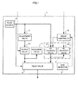
- FIG. 1 is a block diagram illustrating a configurational example of the brake control device according to an embodiment of the present invention.
- a brake control device 1 according to the embodiment supplies pressure-adjusted fluid to a brake cylinder, thereby performing brake control of an electric rolling stock.
- the brake control device 1 includes a fluid source 2, an adjustment valve 3, a control valve 4, a relay valve 5, a brake controller 6, a skid detector 7, an output valve 10, and a discharge valve 11.
- the control valve 4 includes an AV solenoid valve 8 that is a solenoid valve for supplying air and an RV solenoid valve 9 that is a solenoid valve for discharging air.
- the brake control device 1 is disposed, for example, in an electric rolling stock to adjust the air pressure supplied by the fluid source 2 and then sends the pressure-adjusted air to the brake cylinder.
- the adjustment valve 3 adjusts the air supplied from the fluid source 2 to a predetermined pressure to output the pressure-adjusted air.
- the pressure of air output by the adjustment valve 3 is constant.
- the air output by the adjustment valve 3 and a switching command as illustrated by a dotted line in FIG. 1 are input to the output valve 10.
- the switching command refers, for example, to a command from a motorman's cab or a command from another car-mounted device such as an Automatic Train Control (ATC) and the like, which is a command for causing an emergency brake or an auxiliary brake to operate.
- ATC Automatic Train Control
- the output valve 10 switches opening and closing based on a switching command, and outputs air output by the adjustment valve 3 when a switching command is input, and does not output the air output by the adjustment valve 3 when no switching command is input.
- the skid detector 7 detects whether a car including the brake control device 1 is skidding or not.
- the skid detector 7 detects occurrence of a skid, for example, when a shaft speed of an axle is less than a reference shaft speed by at least a certain value to notify the brake controller 6 of the detected skid.
- the certain value refers to an optional value determined by design. Further, for example, when detecting that a shaft speed of an axle has started increasing after occurrence of a skid, the skid detector 7 considers the wheels to have re-adhered to the rail, and then notifies the brake controller 6.
- a brake command from the motorman's cab is input to the brake controller 6 as illustrated by a dotted line in FIG. 1 .
- the brake controller 6 issues commands to the AV solenoid valve 8, the RV solenoid valve 9, and the discharge valve 11 based on the brake command and the detection result of the skid detector 7.
- the brake controller 6 issues commands to the AV solenoid valve 8 and the RV solenoid valve 9 so as to obtain a necessary brake force based on the brake command.
- the brake controller 6 issues a command to the AV solenoid valve 8 so as not to supply air from the AV solenoid valve 8 and issues a command to the RV solenoid valve 9 so as to discharge air from the RV solenoid valve 9.
- the brake controller 6 issues a command to the discharge valve 11 so as to discharge air from the discharge valve 11.
- the brake controller 6 issues a command to the AV solenoid valve 8 so as to supply air from the AV solenoid valve 8 and issues a command to the RV solenoid valve 9 so as not to discharge air from the RV solenoid valve 9.
- the brake controller 6 issues a command to the discharge valve 11 so as not to discharge air from the discharge valve 11.
- Air is supplied from the fluid source 2 to the AV solenoid valve 8. Then, air pressure-adjusted by the AV solenoid valve 8 and the RV solenoid valve 9 is sent to the relay valve 5. A pressure of air output by the output valve 10 is controlled by the discharge valve 11 to send the pressure-controlled air to the relay valve 5.
- the relay valve 5 adjusts a pressure of air supplied from the fluid source 2 based on a higher pressure between a pressure of air output by the output valve 10 controlled by the discharge valve 11 and a pressure of air output by the control valve 4 to output the pressure-adjusted air to the brake cylinder.
- the relay valve 5 adjusts a pressure of air supplied from the fluid source 2 based on a higher one of a pressure of air output by the output valve 10 controlled by the discharge valve 11 and a pressure of air output by the control valve 4 to output the pressure-adjusted air to the brake cylinder.
- FIGS. 2A and 2B are charts illustrating changes in pressure during skid control in the brake control device according to the embodiment.
- the horizontal axis indicates time and the vertical axis indicates a pressure of air output by each valve. Description will be made on an example, in which a brake command is input at a time T0, a skid is detected by the skid detector 7 at a time T1, and wheel re-adhesion is detected by the skid detector 7 at a time T2.
- FIG. 2A illustrates a case where no switching command is input
- FIG. 2B illustrates a case where a switching command is input.
- the output valve 10 when no switching command is input, the output valve 10 does not output air output by the adjustment valve 3. In other words, an output of the adjustment valve 3 illustrated in a first stage is not output from the output valve 10 to the relay valve 5 as illustrated in a second stage.
- the control valve 4 controls air supplied from the fluid source 2 based on a command from the brake controller 6 and outputs the thus-controlled air.
- the pressure of air output by the control valve 4 is gradually increased after a brake command is input at the time T0 as illustrated in a third stage, and then held at a certain value. Thereafter, when a skid is detected at the time T1, the pressure of air output by the control valve 4 is gradually decreased in accordance with a command from the brake controller 6. When wheel re-adhesion is detected at the time T2, the pressure of air output by the control valve 4 is increased again and then held at a certain value.
- the relay valve 5 adjusts the pressure of air supplied from the fluid source 2 to output the pressure-adjusted air to the brake cylinder, based on a higher one of a pressure of air output by the output valve 10 and the pressure of air output by the control valve 4, in other words, based on a pressure of air output by the control valve 4 in the case of FIG. 2A .
- the output valve 10 when a switching command is input, the output valve 10 outputs air output by the adjustment valve 3. In other words, an output of the adjustment valve 3 illustrated in the first stage is output from the output valve 10 to the relay valve 5.
- the discharge valve 11 controls air output by the output valve 10 based on a command from the brake controller 6.
- the discharge valve 11 discharges air output by the output valve 10 in accordance with the command from the brake controller 6.
- a pressure of air output by the output valve 10 adjusted by the discharge valve 11 is the same as an output of the adjustment valve 3 illustrated in the first stage of FIG. 2B until the time T1.
- the pressure is decreased when a discharge from the discharge valve 11 is initiated at the time T1.
- the discharge valve 11 stops discharging air output by the output valve 10 in accordance with a command from the brake controller 6. As illustrated in the second stage, a pressure of air output by the output valve 10 adjusted by the discharge valve 11 is increased again from the time T2 and then held at a certain value.
- the control valve 4 adjusts a pressure of air supplied from the fluid source 2 based on a command from the brake controller 6 to output the pressure-adjusted air.
- An output of the control valve 4 is the same as in the case of FIG. 2A .
- the relay valve 5 adjusts a pressure of air supplied from the fluid source 2 based on a higher one of a pressure of air output by the output valve 10 adjusted by the discharge valve 11 and a pressure of air output by the control valve 4 to output the pressure-adjusted air to the brake cylinder.
- a pressure of air output by the control valve 4 is less than a pressure of air output by the output valve 10.
- the relay valve 5 adjusts a pressure of air supplied from the fluid source 2 based on an output of the output valve 10 from the time T0 until the time T1' and after the time T2, and adjusts the pressure of air supplied from the fluid source 2 based on an output of the control valve 4 from the time T1' until the time T2 to output the pressure-adjusted air to the brake cylinder.
- skid control can be performed regardless of a magnitude relationship among command pressures of a plurality of systems, even without providing skid control processing for each command pressure.
- FIG. 3 is a flowchart illustrating one example of a control operation performed by the brake control device according to the embodiment.
- the discharge valve 11 discharges air output by the output valve 10 when a skid is detected, based on a command from the brake controller 6 according to a brake command and a detection result of the skid detector 7, and thereafter stops discharging the air output by the output valve 10 when re-adhesion is detected to adjust an output of the output valve 10 (step S130).
- the control valve 4 adjusts a pressure of input air to output the pressure-adjusted air, based on the command from the brake controller 6 according to the brake command and the detection result of the skid detector 7 (step S 140).
- the relay valve 5 adjusts a pressure of air supplied from the fluid source 2 based on a higher pressure between a pressure of air output by the output valve 10 and a pressure of air output by the control valve 4 to output the pressure-adjusted air to the brake cylinder (step S 150).
- skid control in brake control based on a plurality of commands that are a brake command and a switching command, skid control can be performed.
- the size of the brake control device 1 can be made smaller.
- the relay valve 5 makes it possible to realize higher-level priority control, in which a pressure of air from the fluid source 2 is adjusted based on a higher pressure between the pressures of input air and the pressure-adjusted air is output to the brake cylinder.
- discharging of air output by the output valve 10 from the discharge valve 11 during skid detection makes it possible to realize skid control while higher-level priority control is performed in the relay valve 5, regardless of a magnitude relationship between an output of the output valve 10 and an output of the control valve 4.
- a configuration where the skid detector 7 is disposed only on the control valve 4 side simplifies the configuration of the device.
- the brake control device 1 of the embodiment in brake control based on commands of a plurality of systems, it is possible to simplify a configuration for performing skid control and to perform skid control regardless of a magnitude relationship among command pressures of a plurality of systems.
- the concept of the present invention is not limited to the aforementioned embodiment.
- the number of command pressure systems is not limited to two, and the brake control device 1 may include, for example, a plurality of control valves 4 that are controlled based on different brake commands, or a plurality of adjustment valves 3 and a plurality of output valves 10 that are controlled based on different switching commands.
Landscapes
- Engineering & Computer Science (AREA)
- Transportation (AREA)
- Mechanical Engineering (AREA)
- Regulating Braking Force (AREA)
- Braking Systems And Boosters (AREA)
- Valves And Accessory Devices For Braking Systems (AREA)
Abstract
Description
- This application relates to a brake control device and a brake control method.
- In a brake control device of a rail car, from a fail-safe point of view, commands of a plurality of systems are input to the brake control device. Based on any one of the commands, a relay valve adjusts, for example, an air pressure from an air source and outputs the pressure-adjusted air to a brake cylinder, whereby a brake of a rail car can be controlled based on the commands of a plurality of systems.
- In an air brake device of an electric rolling stock disclosed in Unexamined Japanese Patent Application Kokai Publication
JP-A-2001-018 784 JP-A-H8-290 765 - A solenoid valve controlling an output of a relay valve is larger than a solenoid valve controlling a command pressure input to the relay valve. In the air brake device of an electric rolling stock disclosed in Unexamined Japanese Patent Application Kokai Publication
JP-A-2001-018 784 JP-A-H8-290 765 - Further, there is a brake control device performing control in such a manner that command pressures of two systems are provided for a relay valve, and air on a higher-level priority basis, in other words, air based on a higher command pressure in the relay valve is output to a brake cylinder.
- In the relay valve of this brake control device, regardless of a magnitude relationship between the command pressures of two systems, when brake control and skid control are performed, it is necessary to provide a solenoid valve for skid control for each of the plurality of command pressures. Accordingly, the device size is enlarged.
- The present invention has been conceived in view of the above circumstances and an exemplary object of the present invention is to ensure higher-level priority and simplify a configuration for performing skid control in brake control based on commands of a plurality of systems.
- To achieve the object, a brake control device of the present invention includes a fluid source that is a supply source of fluid, a skid detector, an adjustment valve, an output valve, a discharge valve, a control valve, and a relay valve. The skid detector detects a skid of a car. The adjustment valve adjusts a pressure of the fluid supplied from the fluid source to a predetermined pressure and output the thus-adjusted fluid.
- The output valve outputs the fluid output by the adjustment valve when the fluid output by the adjustment valve is input and a switching command is input, and does not output the fluid output by the adjustment valve when no switching command is input. The discharge valve depressurizes an output by the output valve based on a detection result of the skid detector.
- The control valve adjusts, based on a brake command and the detection result of the skid detector, a pressure of the fluid supplied from the fluid source to output the pressure-adjusted fluid. The relay valve adjusts, based on a higher pressure between pressures of the fluid output by the output valve and pressures of the fluid output by the control valve, a pressure of the fluid supplied from the fluid source to output the pressure-adjusted fluid to a brake cylinder.
- According to the present invention, in the brake control based on commands of a plurality of systems, higher-level priority can be ensured and a configuration for performing skid control can be simplified.
- A more complete understanding of this application can be obtained when the following detailed description is considered in conjunction with the following drawings, in which:
- FIG. 1
- is a block diagram illustrating a configurational example of a brake control device according to an embodiment of the present invention;
- FIG. 2A
- is a chart illustrating changes in pressure during skid control in a case where no switching command is input, in the brake control device according to the embodiment;
- FIG. 2B
- is a chart illustrating changes in pressure during skid control in a case where a switching command is input, in the brake control device according to the embodiment; and
- FIG. 3
- is a flowchart illustrating one example of a control operation performed by the brake control device according to the embodiment.
- An embodiment of the present invention will now be described in detail with reference to the accompanying drawings. In the figures, the same signs will be assigned to the same or equivalent parts.
-
FIG. 1 is a block diagram illustrating a configurational example of the brake control device according to an embodiment of the present invention. A brake control device 1 according to the embodiment supplies pressure-adjusted fluid to a brake cylinder, thereby performing brake control of an electric rolling stock. - Examples of the fluid include air and oil. In the present embodiment, air is used as the fluid. The brake control device 1 includes a
fluid source 2, anadjustment valve 3, acontrol valve 4, arelay valve 5, abrake controller 6, a skid detector 7, anoutput valve 10, and a discharge valve 11. - The
control valve 4 includes anAV solenoid valve 8 that is a solenoid valve for supplying air and an RV solenoid valve 9 that is a solenoid valve for discharging air. The brake control device 1 is disposed, for example, in an electric rolling stock to adjust the air pressure supplied by thefluid source 2 and then sends the pressure-adjusted air to the brake cylinder. - The
adjustment valve 3 adjusts the air supplied from thefluid source 2 to a predetermined pressure to output the pressure-adjusted air. The pressure of air output by theadjustment valve 3 is constant. The air output by theadjustment valve 3 and a switching command as illustrated by a dotted line inFIG. 1 are input to theoutput valve 10. - The switching command refers, for example, to a command from a motorman's cab or a command from another car-mounted device such as an Automatic Train Control (ATC) and the like, which is a command for causing an emergency brake or an auxiliary brake to operate. The
output valve 10 switches opening and closing based on a switching command, and outputs air output by theadjustment valve 3 when a switching command is input, and does not output the air output by theadjustment valve 3 when no switching command is input. - The skid detector 7 detects whether a car including the brake control device 1 is skidding or not. The skid detector 7 detects occurrence of a skid, for example, when a shaft speed of an axle is less than a reference shaft speed by at least a certain value to notify the
brake controller 6 of the detected skid. - The certain value refers to an optional value determined by design. Further, for example, when detecting that a shaft speed of an axle has started increasing after occurrence of a skid, the skid detector 7 considers the wheels to have re-adhered to the rail, and then notifies the
brake controller 6. - In addition to a notice from the skid detector 7, for example, a brake command from the motorman's cab is input to the
brake controller 6 as illustrated by a dotted line inFIG. 1 . Thebrake controller 6 issues commands to theAV solenoid valve 8, the RV solenoid valve 9, and the discharge valve 11 based on the brake command and the detection result of the skid detector 7. Thebrake controller 6 issues commands to theAV solenoid valve 8 and the RV solenoid valve 9 so as to obtain a necessary brake force based on the brake command. - For example, when the skid detector 7 has detected a skid, in order to reduce a pressure of air output by the
control valve 4, thebrake controller 6 issues a command to theAV solenoid valve 8 so as not to supply air from theAV solenoid valve 8 and issues a command to the RV solenoid valve 9 so as to discharge air from the RV solenoid valve 9. - Further, when the skid detector 7 has detected the skid, in order to reduce the pressure of air output by the
output valve 10, thebrake controller 6 issues a command to the discharge valve 11 so as to discharge air from the discharge valve 11. - Thereafter, when the skid detector 7 has detected wheel re-adhesion, in order to obtain a necessary brake force based on a brake command, the
brake controller 6 issues a command to theAV solenoid valve 8 so as to supply air from theAV solenoid valve 8 and issues a command to the RV solenoid valve 9 so as not to discharge air from the RV solenoid valve 9. - Further, when the skid detector 7 has detected the wheel re-adhesion, in order to match a pressure of air output by the
output valve 10 with a pressure of air output by theadjustment valve 3, thebrake controller 6 issues a command to the discharge valve 11 so as not to discharge air from the discharge valve 11. - Air is supplied from the
fluid source 2 to theAV solenoid valve 8. Then, air pressure-adjusted by theAV solenoid valve 8 and the RV solenoid valve 9 is sent to therelay valve 5. A pressure of air output by theoutput valve 10 is controlled by the discharge valve 11 to send the pressure-controlled air to therelay valve 5. - The
relay valve 5 adjusts a pressure of air supplied from thefluid source 2 based on a higher pressure between a pressure of air output by theoutput valve 10 controlled by the discharge valve 11 and a pressure of air output by thecontrol valve 4 to output the pressure-adjusted air to the brake cylinder. In the example ofFIG. 1 , therelay valve 5 adjusts a pressure of air supplied from thefluid source 2 based on a higher one of a pressure of air output by theoutput valve 10 controlled by the discharge valve 11 and a pressure of air output by thecontrol valve 4 to output the pressure-adjusted air to the brake cylinder. -
FIGS. 2A and2B are charts illustrating changes in pressure during skid control in the brake control device according to the embodiment. The horizontal axis indicates time and the vertical axis indicates a pressure of air output by each valve. Description will be made on an example, in which a brake command is input at a time T0, a skid is detected by the skid detector 7 at a time T1, and wheel re-adhesion is detected by the skid detector 7 at a time T2.FIG. 2A illustrates a case where no switching command is input andFIG. 2B illustrates a case where a switching command is input. - As illustrated in
FIG. 2A , when no switching command is input, theoutput valve 10 does not output air output by theadjustment valve 3. In other words, an output of theadjustment valve 3 illustrated in a first stage is not output from theoutput valve 10 to therelay valve 5 as illustrated in a second stage. Thecontrol valve 4 controls air supplied from thefluid source 2 based on a command from thebrake controller 6 and outputs the thus-controlled air. - The pressure of air output by the
control valve 4 is gradually increased after a brake command is input at the time T0 as illustrated in a third stage, and then held at a certain value. Thereafter, when a skid is detected at the time T1, the pressure of air output by thecontrol valve 4 is gradually decreased in accordance with a command from thebrake controller 6. When wheel re-adhesion is detected at the time T2, the pressure of air output by thecontrol valve 4 is increased again and then held at a certain value. - As illustrated in a fourth stage of
FIG. 2A , therelay valve 5 adjusts the pressure of air supplied from thefluid source 2 to output the pressure-adjusted air to the brake cylinder, based on a higher one of a pressure of air output by theoutput valve 10 and the pressure of air output by thecontrol valve 4, in other words, based on a pressure of air output by thecontrol valve 4 in the case ofFIG. 2A . - As illustrated in
FIG. 2B , when a switching command is input, theoutput valve 10 outputs air output by theadjustment valve 3. In other words, an output of theadjustment valve 3 illustrated in the first stage is output from theoutput valve 10 to therelay valve 5. The discharge valve 11 controls air output by theoutput valve 10 based on a command from thebrake controller 6. - When a skid is detected at the time T1, the discharge valve 11 discharges air output by the
output valve 10 in accordance with the command from thebrake controller 6. As illustrated in the second stage, a pressure of air output by theoutput valve 10 adjusted by the discharge valve 11 is the same as an output of theadjustment valve 3 illustrated in the first stage ofFIG. 2B until the time T1. However, the pressure is decreased when a discharge from the discharge valve 11 is initiated at the time T1. - Thereafter, when wheel re-adhesion is detected at the time T2, the discharge valve 11 stops discharging air output by the
output valve 10 in accordance with a command from thebrake controller 6. As illustrated in the second stage, a pressure of air output by theoutput valve 10 adjusted by the discharge valve 11 is increased again from the time T2 and then held at a certain value. - The
control valve 4 adjusts a pressure of air supplied from thefluid source 2 based on a command from thebrake controller 6 to output the pressure-adjusted air. An output of thecontrol valve 4 is the same as in the case ofFIG. 2A . - As illustrated in a fourth stage of
FIG. 2B , therelay valve 5 adjusts a pressure of air supplied from thefluid source 2 based on a higher one of a pressure of air output by theoutput valve 10 adjusted by the discharge valve 11 and a pressure of air output by thecontrol valve 4 to output the pressure-adjusted air to the brake cylinder. In the case ofFIG. 2B , from the time T0 until a time T1' and after the time T2, a pressure of air output by thecontrol valve 4 is less than a pressure of air output by theoutput valve 10. - Therefore, the
relay valve 5 adjusts a pressure of air supplied from thefluid source 2 based on an output of theoutput valve 10 from the time T0 until the time T1' and after the time T2, and adjusts the pressure of air supplied from thefluid source 2 based on an output of thecontrol valve 4 from the time T1' until the time T2 to output the pressure-adjusted air to the brake cylinder. - Even when an output of the
adjustment valve 3 is greater than an output of thecontrol valve 4, during skid detection, air is discharged from the discharge valve 11 to adjust a pressure of air output by theoutput valve 10 to enable skid control. - As illustrated in
FIG. 2A andFIG. 2B , when thecontrol valve 4 is controlled by a detection result of the skid controller 7 and the discharge valve 11 is disposed on theoutput valve 10 side, in brake control based on commands of a plurality of systems, skid control can be performed regardless of a magnitude relationship among command pressures of a plurality of systems, even without providing skid control processing for each command pressure. -
FIG. 3 is a flowchart illustrating one example of a control operation performed by the brake control device according to the embodiment. When a switching command is input (step S110; YES), theoutput valve 10 outputs air that was output by theadjustment valve 3 to the relay valve 5 (step S120). When no switching command is input (step S110; NO), without performing step S120, theoutput valve 10 does not output air output by theadjustment valve 3 to therelay valve 5. - The discharge valve 11 discharges air output by the
output valve 10 when a skid is detected, based on a command from thebrake controller 6 according to a brake command and a detection result of the skid detector 7, and thereafter stops discharging the air output by theoutput valve 10 when re-adhesion is detected to adjust an output of the output valve 10 (step S130). - The
control valve 4 adjusts a pressure of input air to output the pressure-adjusted air, based on the command from thebrake controller 6 according to the brake command and the detection result of the skid detector 7 (step S 140). - The
relay valve 5 adjusts a pressure of air supplied from thefluid source 2 based on a higher pressure between a pressure of air output by theoutput valve 10 and a pressure of air output by thecontrol valve 4 to output the pressure-adjusted air to the brake cylinder (step S 150). - In the brake control device 1 according to the embodiment, in brake control based on a plurality of commands that are a brake command and a switching command, skid control can be performed.
- Further, it is not necessary to provide a solenoid valve between the
relay valve 5 and the brake cylinder, and therefore, the size of the brake control device 1 can be made smaller. - Moreover, the
relay valve 5 makes it possible to realize higher-level priority control, in which a pressure of air from thefluid source 2 is adjusted based on a higher pressure between the pressures of input air and the pressure-adjusted air is output to the brake cylinder. - Further, discharging of air output by the
output valve 10 from the discharge valve 11 during skid detection makes it possible to realize skid control while higher-level priority control is performed in therelay valve 5, regardless of a magnitude relationship between an output of theoutput valve 10 and an output of thecontrol valve 4. In addition, a configuration where the skid detector 7 is disposed only on thecontrol valve 4 side simplifies the configuration of the device. - As has been described above, according to the brake control device 1 of the embodiment, in brake control based on commands of a plurality of systems, it is possible to simplify a configuration for performing skid control and to perform skid control regardless of a magnitude relationship among command pressures of a plurality of systems.
- The concept of the present invention is not limited to the aforementioned embodiment. The number of command pressure systems is not limited to two, and the brake control device 1 may include, for example, a plurality of
control valves 4 that are controlled based on different brake commands, or a plurality ofadjustment valves 3 and a plurality ofoutput valves 10 that are controlled based on different switching commands. - Having described and illustrated the principles of this application by reference to one preferred embodiment, it should be apparent that the preferred embodiment may be modified in arrangement and detail without departing from the principles disclosed herein and that it is intended that the application be construed as including all such modifications and variations insofar as they come within the spirit and scope of the subject matter disclosed herein.
-
- 1
- brake control device
- 2
- fluid source
- 3
- adjustment valve
- 4
- control valve
- 5
- relay valve
- 6
- brake controller
- 7
- skid detector
- 8
- AV solenoid valve
- 9
- RV solenoid valve
- 10
- output valve
- 11
- discharge valve
Claims (2)
- A brake control device (1) characterized by comprising:- a fluid source (2) that is a supply source of fluid;- a skid detector (7) adapted for detecting a skid of a car;- an adjustment valve (3) adapted for adjusting a pressure of the fluid supplied from the fluid source (2) to a predetermined pressure and outputting pressure-adjusted fluid;- an output valve (10) adapted for receiving the fluid output by the adjustment valve (3), the output valve (10) being adapted for outputting the fluid output by the adjustment valve (3) when a switching command is input and not outputting the fluid output by the adjustment valve (3) when the switching command is not input;- a discharge valve (11) adapted for depressurizing an output by the output valve (10) based on a detection result of the skid detector (7);- a control valve (4) adapted for adjusting a pressure of the fluid supplied from the fluid source (2) based on a brake command and the detection result of the skid detector (7) to output the pressure-adjusted fluid; and- a relay valve (5) adapted for adjusting a pressure of the fluid supplied from the fluid source (2) based on a higher pressure between a pressure of the fluid output by the output valve (10) and a pressure of the fluid output by the control valve (4) to output the pressure-adjusted fluid to a brake cylinder.
- A brake control method performed by a brake control device (1) comprising a fluid source (2) that is a supply source of fluid, the brake control method characterized by comprising:- a skid detection step of detecting a skid of a car;- an adjustment step
of adjusting a pressure of the fluid supplied from the fluid source (2) to a predetermined pressure to output pressure-adjusted fluid;- an output step of receiving the fluid output in the adjustment step, outputting the fluid output in the adjustment step when a switching command is input, and not outputting the fluid output in the adjustment step when the switching command is not input;- a discharge step of depressurizing an output in the output step based on a detection result in the skid detection step;- a control step of adjusting a pressure of the fluid supplied from the fluid source (2) based on a brake command and the detection result in the skid detection step to output the pressure-adjusted fluid; and- a relay step of adjusting a pressure of the fluid supplied from the fluid source (2) based on a higher pressure between a pressure of the fluid output in the output step and a pressure of the fluid output in the control step to output the pressure-adjusted fluid to a brake cylinder.
Applications Claiming Priority (1)
| Application Number | Priority Date | Filing Date | Title |
|---|---|---|---|
| JP2013094549A JP5900891B2 (en) | 2013-04-26 | 2013-04-26 | Brake control device and brake control method |
Publications (2)
| Publication Number | Publication Date |
|---|---|
| EP2862762A1 true EP2862762A1 (en) | 2015-04-22 |
| EP2862762B1 EP2862762B1 (en) | 2016-10-26 |
Family
ID=50513787
Family Applications (1)
| Application Number | Title | Priority Date | Filing Date |
|---|---|---|---|
| EP14165547.2A Not-in-force EP2862762B1 (en) | 2013-04-26 | 2014-04-23 | Brake control device and brake control method |
Country Status (6)
| Country | Link |
|---|---|
| US (1) | US9457776B2 (en) |
| EP (1) | EP2862762B1 (en) |
| JP (1) | JP5900891B2 (en) |
| KR (1) | KR101650619B1 (en) |
| CN (1) | CN104118413B (en) |
| CA (1) | CA2849851C (en) |
Families Citing this family (9)
| Publication number | Priority date | Publication date | Assignee | Title |
|---|---|---|---|---|
| DE102013016877B3 (en) * | 2013-10-11 | 2014-10-09 | Knorr-Bremse Systeme für Nutzfahrzeuge GmbH | Method for controlling a pressure control device of a pressure medium brake system of a vehicle |
| US12509037B2 (en) | 2014-11-13 | 2025-12-30 | Faiveley Transport Italia S.P.A. | Vehicle braking assembly |
| CN107107897B (en) * | 2014-11-13 | 2019-08-09 | 法伊韦利传送器意大利有限公司 | Electropneumatic components specifically for the installation of pneumatic brakes on rail vehicles |
| IT201700040680A1 (en) * | 2017-04-12 | 2018-10-12 | Faiveley Transport Italia Spa | Electronic emergency and service braking control system for a railway vehicle. |
| IT201900003423A1 (en) * | 2019-03-08 | 2020-09-08 | Faiveley Transport Italia Spa | Supervisor device for monitoring the operation of an anti-skid device of a railway braking system |
| JP2021115928A (en) * | 2020-01-24 | 2021-08-10 | ナブテスコ株式会社 | Railway vehicle relay valve status determination device, railway vehicle regular solenoid valve status determination device, railway vehicle relay valve status determination program, railway vehicle conventional solenoid valve status determination program, and railway vehicle brake control device |
| JP2021123246A (en) * | 2020-02-05 | 2021-08-30 | ナブテスコ株式会社 | Skid control device for railroad vehicle and method for controlling skid control device for railroad vehicle |
| CN116442971B (en) * | 2022-01-06 | 2025-10-28 | 株洲中车时代电气股份有限公司 | A vehicle braking system |
| DE102022104881B4 (en) * | 2022-03-02 | 2026-05-07 | Knorr-Bremse Systeme für Schienenfahrzeuge GmbH | Braking system for a rail vehicle and method for controlling such a braking system |
Citations (5)
| Publication number | Priority date | Publication date | Assignee | Title |
|---|---|---|---|---|
| JPH08290765A (en) | 1995-04-20 | 1996-11-05 | Nabco Ltd | Brake control device for rolling stock |
| US5775367A (en) * | 1996-02-22 | 1998-07-07 | Westinghouse Air Brake Company | Solenoid valve control device |
| JP2001018784A (en) | 1999-07-02 | 2001-01-23 | Mitsubishi Electric Corp | Electric vehicle air brake device and air brake method |
| US6669308B1 (en) * | 1998-10-23 | 2003-12-30 | Knorr-Bremse Systeme für Schienenfahrzeuge GmbH | Brake system for railway vehicles |
| US20110089755A1 (en) * | 2008-07-24 | 2011-04-21 | Mitsubishi Electric Corporation | Train braking device |
Family Cites Families (7)
| Publication number | Priority date | Publication date | Assignee | Title |
|---|---|---|---|---|
| US3093399A (en) * | 1961-03-06 | 1963-06-11 | Gen Electric | Wheel slip suppression system |
| US5494342A (en) * | 1994-06-14 | 1996-02-27 | New York Air Brake Corporation | Electropneumatic brake control system |
| ITTO20031044A1 (en) * | 2003-12-24 | 2005-06-25 | Sab Wabco Spa | BRAKING SYSTEM FOR A RAIL VEHICLE AUTOMOTOR PROVIDED WITH AN ANTI-POLLUTION. |
| JP4843198B2 (en) * | 2004-03-31 | 2011-12-21 | 公益財団法人鉄道総合技術研究所 | Anti-lock brake system for railway vehicles and braking control method for railway vehicles |
| US20070173990A1 (en) * | 2006-01-11 | 2007-07-26 | Smith Eugene A | Traction control for remotely controlled locomotive |
| US7520574B2 (en) * | 2006-03-28 | 2009-04-21 | Wabtec Holding Corporation | Pneumatic emergency brake release timer |
| JP5244557B2 (en) * | 2008-11-25 | 2013-07-24 | ナブテスコ株式会社 | Brake control device |
-
2013
- 2013-04-26 JP JP2013094549A patent/JP5900891B2/en active Active
-
2014
- 2014-04-23 KR KR1020140048764A patent/KR101650619B1/en not_active Expired - Fee Related
- 2014-04-23 EP EP14165547.2A patent/EP2862762B1/en not_active Not-in-force
- 2014-04-24 US US14/260,738 patent/US9457776B2/en not_active Expired - Fee Related
- 2014-04-24 CA CA2849851A patent/CA2849851C/en not_active Expired - Fee Related
- 2014-04-25 CN CN201410172421.2A patent/CN104118413B/en active Active
Patent Citations (5)
| Publication number | Priority date | Publication date | Assignee | Title |
|---|---|---|---|---|
| JPH08290765A (en) | 1995-04-20 | 1996-11-05 | Nabco Ltd | Brake control device for rolling stock |
| US5775367A (en) * | 1996-02-22 | 1998-07-07 | Westinghouse Air Brake Company | Solenoid valve control device |
| US6669308B1 (en) * | 1998-10-23 | 2003-12-30 | Knorr-Bremse Systeme für Schienenfahrzeuge GmbH | Brake system for railway vehicles |
| JP2001018784A (en) | 1999-07-02 | 2001-01-23 | Mitsubishi Electric Corp | Electric vehicle air brake device and air brake method |
| US20110089755A1 (en) * | 2008-07-24 | 2011-04-21 | Mitsubishi Electric Corporation | Train braking device |
Also Published As
| Publication number | Publication date |
|---|---|
| JP5900891B2 (en) | 2016-04-06 |
| KR101650619B1 (en) | 2016-08-23 |
| JP2014213809A (en) | 2014-11-17 |
| US20140319904A1 (en) | 2014-10-30 |
| KR20140128252A (en) | 2014-11-05 |
| CN104118413B (en) | 2017-07-25 |
| CN104118413A (en) | 2014-10-29 |
| CA2849851A1 (en) | 2014-10-26 |
| CA2849851C (en) | 2017-01-17 |
| EP2862762B1 (en) | 2016-10-26 |
| US9457776B2 (en) | 2016-10-04 |
Similar Documents
| Publication | Publication Date | Title |
|---|---|---|
| EP2862762B1 (en) | Brake control device and brake control method | |
| EP2334526B1 (en) | Electropneumatic brake device and method for operating the same | |
| DE102012009427B4 (en) | Control valve device for a rail vehicle brake | |
| US9296399B2 (en) | Method for controlling a compressed-air braking device of a rail vehicle in the case of automatic, quick, or emergency braking | |
| US11932219B2 (en) | Control device and method for controlling an actuator for actuating braking means of a vehicle, more particularly of a rail vehicle | |
| US9776611B2 (en) | Method for controlling a pneumatic brake system and a pneumatic brake system for a vehicle | |
| EP3636502A1 (en) | Train brake cylinder pressure control system and rail train | |
| KR102624360B1 (en) | Method and brake system for controlling or regulating a brake system | |
| KR101958836B1 (en) | Brake operating unit for railway vehicles | |
| DE102008032715B4 (en) | Electropneumatic brake device of a rail vehicle | |
| EP3585665B1 (en) | Computer controlled brake retainer valve control system | |
| CN108602501B (en) | Brake pressure switching system with time-continuous ramp for a rail vehicle | |
| CN110857083B (en) | Electronically slide-adjustable power-assisted braking device and method for reducing brake pressure present in its brake circuit | |
| US20250153691A1 (en) | Brake system for a rail vehicle, and method for controlling such a brake system | |
| CN106740917A (en) | A kind of engineering detecting binding group locomotive and its brake control method and system again | |
| EP3473517B1 (en) | Rail vehicle brake control device and rail vehicle brake control method | |
| WO2023202962A1 (en) | Device and method for operating an electromagnetic rail brake, electromagnetic rail brake and rail vehicle |
Legal Events
| Date | Code | Title | Description |
|---|---|---|---|
| PUAI | Public reference made under article 153(3) epc to a published international application that has entered the european phase |
Free format text: ORIGINAL CODE: 0009012 |
|
| 17P | Request for examination filed |
Effective date: 20140423 |
|
| AK | Designated contracting states |
Kind code of ref document: A1 Designated state(s): AL AT BE BG CH CY CZ DE DK EE ES FI FR GB GR HR HU IE IS IT LI LT LU LV MC MK MT NL NO PL PT RO RS SE SI SK SM TR |
|
| AX | Request for extension of the european patent |
Extension state: BA ME |
|
| R17P | Request for examination filed (corrected) |
Effective date: 20151014 |
|
| RBV | Designated contracting states (corrected) |
Designated state(s): AL AT BE BG CH CY CZ DE DK EE ES FI FR GB GR HR HU IE IS IT LI LT LU LV MC MK MT NL NO PL PT RO RS SE SI SK SM TR |
|
| GRAP | Despatch of communication of intention to grant a patent |
Free format text: ORIGINAL CODE: EPIDOSNIGR1 |
|
| INTG | Intention to grant announced |
Effective date: 20160506 |
|
| GRAS | Grant fee paid |
Free format text: ORIGINAL CODE: EPIDOSNIGR3 |
|
| GRAA | (expected) grant |
Free format text: ORIGINAL CODE: 0009210 |
|
| AK | Designated contracting states |
Kind code of ref document: B1 Designated state(s): AL AT BE BG CH CY CZ DE DK EE ES FI FR GB GR HR HU IE IS IT LI LT LU LV MC MK MT NL NO PL PT RO RS SE SI SK SM TR |
|
| REG | Reference to a national code |
Ref country code: GB Ref legal event code: FG4D |
|
| REG | Reference to a national code |
Ref country code: CH Ref legal event code: EP |
|
| REG | Reference to a national code |
Ref country code: AT Ref legal event code: REF Ref document number: 839769 Country of ref document: AT Kind code of ref document: T Effective date: 20161115 |
|
| REG | Reference to a national code |
Ref country code: IE Ref legal event code: FG4D |
|
| REG | Reference to a national code |
Ref country code: DE Ref legal event code: R096 Ref document number: 602014004430 Country of ref document: DE |
|
| REG | Reference to a national code |
Ref country code: LT Ref legal event code: MG4D |
|
| PG25 | Lapsed in a contracting state [announced via postgrant information from national office to epo] |
Ref country code: LV Free format text: LAPSE BECAUSE OF FAILURE TO SUBMIT A TRANSLATION OF THE DESCRIPTION OR TO PAY THE FEE WITHIN THE PRESCRIBED TIME-LIMIT Effective date: 20161026 |
|
| REG | Reference to a national code |
Ref country code: NL Ref legal event code: MP Effective date: 20161026 |
|
| REG | Reference to a national code |
Ref country code: AT Ref legal event code: MK05 Ref document number: 839769 Country of ref document: AT Kind code of ref document: T Effective date: 20161026 |
|
| PG25 | Lapsed in a contracting state [announced via postgrant information from national office to epo] |
Ref country code: NO Free format text: LAPSE BECAUSE OF FAILURE TO SUBMIT A TRANSLATION OF THE DESCRIPTION OR TO PAY THE FEE WITHIN THE PRESCRIBED TIME-LIMIT Effective date: 20170126 Ref country code: GR Free format text: LAPSE BECAUSE OF FAILURE TO SUBMIT A TRANSLATION OF THE DESCRIPTION OR TO PAY THE FEE WITHIN THE PRESCRIBED TIME-LIMIT Effective date: 20170127 Ref country code: LT Free format text: LAPSE BECAUSE OF FAILURE TO SUBMIT A TRANSLATION OF THE DESCRIPTION OR TO PAY THE FEE WITHIN THE PRESCRIBED TIME-LIMIT Effective date: 20161026 Ref country code: SE Free format text: LAPSE BECAUSE OF FAILURE TO SUBMIT A TRANSLATION OF THE DESCRIPTION OR TO PAY THE FEE WITHIN THE PRESCRIBED TIME-LIMIT Effective date: 20161026 |
|
| PG25 | Lapsed in a contracting state [announced via postgrant information from national office to epo] |
Ref country code: RS Free format text: LAPSE BECAUSE OF FAILURE TO SUBMIT A TRANSLATION OF THE DESCRIPTION OR TO PAY THE FEE WITHIN THE PRESCRIBED TIME-LIMIT Effective date: 20161026 Ref country code: PT Free format text: LAPSE BECAUSE OF FAILURE TO SUBMIT A TRANSLATION OF THE DESCRIPTION OR TO PAY THE FEE WITHIN THE PRESCRIBED TIME-LIMIT Effective date: 20170227 Ref country code: ES Free format text: LAPSE BECAUSE OF FAILURE TO SUBMIT A TRANSLATION OF THE DESCRIPTION OR TO PAY THE FEE WITHIN THE PRESCRIBED TIME-LIMIT Effective date: 20161026 Ref country code: IS Free format text: LAPSE BECAUSE OF FAILURE TO SUBMIT A TRANSLATION OF THE DESCRIPTION OR TO PAY THE FEE WITHIN THE PRESCRIBED TIME-LIMIT Effective date: 20170226 Ref country code: HR Free format text: LAPSE BECAUSE OF FAILURE TO SUBMIT A TRANSLATION OF THE DESCRIPTION OR TO PAY THE FEE WITHIN THE PRESCRIBED TIME-LIMIT Effective date: 20161026 Ref country code: FI Free format text: LAPSE BECAUSE OF FAILURE TO SUBMIT A TRANSLATION OF THE DESCRIPTION OR TO PAY THE FEE WITHIN THE PRESCRIBED TIME-LIMIT Effective date: 20161026 Ref country code: AT Free format text: LAPSE BECAUSE OF FAILURE TO SUBMIT A TRANSLATION OF THE DESCRIPTION OR TO PAY THE FEE WITHIN THE PRESCRIBED TIME-LIMIT Effective date: 20161026 Ref country code: PL Free format text: LAPSE BECAUSE OF FAILURE TO SUBMIT A TRANSLATION OF THE DESCRIPTION OR TO PAY THE FEE WITHIN THE PRESCRIBED TIME-LIMIT Effective date: 20161026 Ref country code: NL Free format text: LAPSE BECAUSE OF FAILURE TO SUBMIT A TRANSLATION OF THE DESCRIPTION OR TO PAY THE FEE WITHIN THE PRESCRIBED TIME-LIMIT Effective date: 20161026 Ref country code: BE Free format text: LAPSE BECAUSE OF FAILURE TO SUBMIT A TRANSLATION OF THE DESCRIPTION OR TO PAY THE FEE WITHIN THE PRESCRIBED TIME-LIMIT Effective date: 20161026 |
|
| REG | Reference to a national code |
Ref country code: DE Ref legal event code: R097 Ref document number: 602014004430 Country of ref document: DE |
|
| PG25 | Lapsed in a contracting state [announced via postgrant information from national office to epo] |
Ref country code: EE Free format text: LAPSE BECAUSE OF FAILURE TO SUBMIT A TRANSLATION OF THE DESCRIPTION OR TO PAY THE FEE WITHIN THE PRESCRIBED TIME-LIMIT Effective date: 20161026 Ref country code: RO Free format text: LAPSE BECAUSE OF FAILURE TO SUBMIT A TRANSLATION OF THE DESCRIPTION OR TO PAY THE FEE WITHIN THE PRESCRIBED TIME-LIMIT Effective date: 20161026 Ref country code: CZ Free format text: LAPSE BECAUSE OF FAILURE TO SUBMIT A TRANSLATION OF THE DESCRIPTION OR TO PAY THE FEE WITHIN THE PRESCRIBED TIME-LIMIT Effective date: 20161026 Ref country code: DK Free format text: LAPSE BECAUSE OF FAILURE TO SUBMIT A TRANSLATION OF THE DESCRIPTION OR TO PAY THE FEE WITHIN THE PRESCRIBED TIME-LIMIT Effective date: 20161026 Ref country code: SK Free format text: LAPSE BECAUSE OF FAILURE TO SUBMIT A TRANSLATION OF THE DESCRIPTION OR TO PAY THE FEE WITHIN THE PRESCRIBED TIME-LIMIT Effective date: 20161026 |
|
| PG25 | Lapsed in a contracting state [announced via postgrant information from national office to epo] |
Ref country code: IT Free format text: LAPSE BECAUSE OF FAILURE TO SUBMIT A TRANSLATION OF THE DESCRIPTION OR TO PAY THE FEE WITHIN THE PRESCRIBED TIME-LIMIT Effective date: 20161026 Ref country code: BG Free format text: LAPSE BECAUSE OF FAILURE TO SUBMIT A TRANSLATION OF THE DESCRIPTION OR TO PAY THE FEE WITHIN THE PRESCRIBED TIME-LIMIT Effective date: 20170126 Ref country code: SM Free format text: LAPSE BECAUSE OF FAILURE TO SUBMIT A TRANSLATION OF THE DESCRIPTION OR TO PAY THE FEE WITHIN THE PRESCRIBED TIME-LIMIT Effective date: 20161026 |
|
| PLBE | No opposition filed within time limit |
Free format text: ORIGINAL CODE: 0009261 |
|
| STAA | Information on the status of an ep patent application or granted ep patent |
Free format text: STATUS: NO OPPOSITION FILED WITHIN TIME LIMIT |
|
| 26N | No opposition filed |
Effective date: 20170727 |
|
| REG | Reference to a national code |
Ref country code: DE Ref legal event code: R119 Ref document number: 602014004430 Country of ref document: DE |
|
| PG25 | Lapsed in a contracting state [announced via postgrant information from national office to epo] |
Ref country code: SI Free format text: LAPSE BECAUSE OF FAILURE TO SUBMIT A TRANSLATION OF THE DESCRIPTION OR TO PAY THE FEE WITHIN THE PRESCRIBED TIME-LIMIT Effective date: 20161026 |
|
| REG | Reference to a national code |
Ref country code: CH Ref legal event code: PL |
|
| REG | Reference to a national code |
Ref country code: IE Ref legal event code: MM4A |
|
| REG | Reference to a national code |
Ref country code: FR Ref legal event code: ST Effective date: 20171229 |
|
| PG25 | Lapsed in a contracting state [announced via postgrant information from national office to epo] |
Ref country code: MC Free format text: LAPSE BECAUSE OF FAILURE TO SUBMIT A TRANSLATION OF THE DESCRIPTION OR TO PAY THE FEE WITHIN THE PRESCRIBED TIME-LIMIT Effective date: 20161026 Ref country code: DE Free format text: LAPSE BECAUSE OF NON-PAYMENT OF DUE FEES Effective date: 20171103 Ref country code: FR Free format text: LAPSE BECAUSE OF NON-PAYMENT OF DUE FEES Effective date: 20170502 |
|
| PG25 | Lapsed in a contracting state [announced via postgrant information from national office to epo] |
Ref country code: CH Free format text: LAPSE BECAUSE OF NON-PAYMENT OF DUE FEES Effective date: 20170430 Ref country code: LI Free format text: LAPSE BECAUSE OF NON-PAYMENT OF DUE FEES Effective date: 20170430 Ref country code: LU Free format text: LAPSE BECAUSE OF NON-PAYMENT OF DUE FEES Effective date: 20170423 |
|
| PG25 | Lapsed in a contracting state [announced via postgrant information from national office to epo] |
Ref country code: IE Free format text: LAPSE BECAUSE OF NON-PAYMENT OF DUE FEES Effective date: 20170423 |
|
| PG25 | Lapsed in a contracting state [announced via postgrant information from national office to epo] |
Ref country code: MT Free format text: LAPSE BECAUSE OF NON-PAYMENT OF DUE FEES Effective date: 20170423 |
|
| GBPC | Gb: european patent ceased through non-payment of renewal fee |
Effective date: 20180423 |
|
| PG25 | Lapsed in a contracting state [announced via postgrant information from national office to epo] |
Ref country code: GB Free format text: LAPSE BECAUSE OF NON-PAYMENT OF DUE FEES Effective date: 20180423 |
|
| PG25 | Lapsed in a contracting state [announced via postgrant information from national office to epo] |
Ref country code: HU Free format text: LAPSE BECAUSE OF FAILURE TO SUBMIT A TRANSLATION OF THE DESCRIPTION OR TO PAY THE FEE WITHIN THE PRESCRIBED TIME-LIMIT; INVALID AB INITIO Effective date: 20140423 |
|
| PG25 | Lapsed in a contracting state [announced via postgrant information from national office to epo] |
Ref country code: CY Free format text: LAPSE BECAUSE OF FAILURE TO SUBMIT A TRANSLATION OF THE DESCRIPTION OR TO PAY THE FEE WITHIN THE PRESCRIBED TIME-LIMIT Effective date: 20161026 |
|
| PG25 | Lapsed in a contracting state [announced via postgrant information from national office to epo] |
Ref country code: MK Free format text: LAPSE BECAUSE OF FAILURE TO SUBMIT A TRANSLATION OF THE DESCRIPTION OR TO PAY THE FEE WITHIN THE PRESCRIBED TIME-LIMIT Effective date: 20161026 |
|
| PG25 | Lapsed in a contracting state [announced via postgrant information from national office to epo] |
Ref country code: TR Free format text: LAPSE BECAUSE OF FAILURE TO SUBMIT A TRANSLATION OF THE DESCRIPTION OR TO PAY THE FEE WITHIN THE PRESCRIBED TIME-LIMIT Effective date: 20161026 |
|
| PG25 | Lapsed in a contracting state [announced via postgrant information from national office to epo] |
Ref country code: AL Free format text: LAPSE BECAUSE OF FAILURE TO SUBMIT A TRANSLATION OF THE DESCRIPTION OR TO PAY THE FEE WITHIN THE PRESCRIBED TIME-LIMIT Effective date: 20161026 |