EP2862759A1 - Pedal assembly module - Google Patents
Pedal assembly module Download PDFInfo
- Publication number
- EP2862759A1 EP2862759A1 EP20140188636 EP14188636A EP2862759A1 EP 2862759 A1 EP2862759 A1 EP 2862759A1 EP 20140188636 EP20140188636 EP 20140188636 EP 14188636 A EP14188636 A EP 14188636A EP 2862759 A1 EP2862759 A1 EP 2862759A1
- Authority
- EP
- European Patent Office
- Prior art keywords
- pedal
- backward
- shaft
- plate
- assembly module
- Prior art date
- Legal status (The legal status is an assumption and is not a legal conclusion. Google has not performed a legal analysis and makes no representation as to the accuracy of the status listed.)
- Granted
Links
Images




Classifications
-
- G—PHYSICS
- G05—CONTROLLING; REGULATING
- G05G—CONTROL DEVICES OR SYSTEMS INSOFAR AS CHARACTERISED BY MECHANICAL FEATURES ONLY
- G05G13/00—Manually-actuated control mechanisms provided with two or more controlling members and also two or more controlled members
-
- B—PERFORMING OPERATIONS; TRANSPORTING
- B60—VEHICLES IN GENERAL
- B60T—VEHICLE BRAKE CONTROL SYSTEMS OR PARTS THEREOF; BRAKE CONTROL SYSTEMS OR PARTS THEREOF, IN GENERAL; ARRANGEMENT OF BRAKING ELEMENTS ON VEHICLES IN GENERAL; PORTABLE DEVICES FOR PREVENTING UNWANTED MOVEMENT OF VEHICLES; VEHICLE MODIFICATIONS TO FACILITATE COOLING OF BRAKES
- B60T7/00—Brake-action initiating means
- B60T7/02—Brake-action initiating means for personal initiation
- B60T7/04—Brake-action initiating means for personal initiation foot actuated
- B60T7/06—Disposition of pedal
-
- G—PHYSICS
- G05—CONTROLLING; REGULATING
- G05G—CONTROL DEVICES OR SYSTEMS INSOFAR AS CHARACTERISED BY MECHANICAL FEATURES ONLY
- G05G1/00—Controlling members, e.g. knobs or handles; Assemblies or arrangements thereof; Indicating position of controlling members
- G05G1/30—Controlling members actuated by foot
- G05G1/36—Mounting units comprising an assembly of two or more pedals, e.g. for facilitating mounting
-
- B—PERFORMING OPERATIONS; TRANSPORTING
- B60—VEHICLES IN GENERAL
- B60K—ARRANGEMENT OR MOUNTING OF PROPULSION UNITS OR OF TRANSMISSIONS IN VEHICLES; ARRANGEMENT OR MOUNTING OF PLURAL DIVERSE PRIME-MOVERS IN VEHICLES; AUXILIARY DRIVES FOR VEHICLES; INSTRUMENTATION OR DASHBOARDS FOR VEHICLES; ARRANGEMENTS IN CONNECTION WITH COOLING, AIR INTAKE, GAS EXHAUST OR FUEL SUPPLY OF PROPULSION UNITS IN VEHICLES
- B60K23/00—Arrangement or mounting of control devices for vehicle transmissions, or parts thereof, not otherwise provided for
- B60K2023/005—Adjusting multiple pedals, e.g. for their initial position
-
- B—PERFORMING OPERATIONS; TRANSPORTING
- B60—VEHICLES IN GENERAL
- B60Y—INDEXING SCHEME RELATING TO ASPECTS CROSS-CUTTING VEHICLE TECHNOLOGY
- B60Y2200/00—Type of vehicle
- B60Y2200/20—Off-Road Vehicles
- B60Y2200/22—Agricultural vehicles
- B60Y2200/221—Tractors
-
- G—PHYSICS
- G05—CONTROLLING; REGULATING
- G05G—CONTROL DEVICES OR SYSTEMS INSOFAR AS CHARACTERISED BY MECHANICAL FEATURES ONLY
- G05G1/00—Controlling members, e.g. knobs or handles; Assemblies or arrangements thereof; Indicating position of controlling members
- G05G1/30—Controlling members actuated by foot
- G05G1/305—Compound pedal co-operating with two or more controlled members
-
- Y—GENERAL TAGGING OF NEW TECHNOLOGICAL DEVELOPMENTS; GENERAL TAGGING OF CROSS-SECTIONAL TECHNOLOGIES SPANNING OVER SEVERAL SECTIONS OF THE IPC; TECHNICAL SUBJECTS COVERED BY FORMER USPC CROSS-REFERENCE ART COLLECTIONS [XRACs] AND DIGESTS
- Y10—TECHNICAL SUBJECTS COVERED BY FORMER USPC
- Y10T—TECHNICAL SUBJECTS COVERED BY FORMER US CLASSIFICATION
- Y10T74/00—Machine element or mechanism
- Y10T74/20—Control lever and linkage systems
- Y10T74/20207—Multiple controlling elements for single controlled element
Definitions
- This invention relates pedal a pedal assembly module.
- tractors used for such as towing the working machine are known (See PTL 1).
- the tractor is equipped with a driver's seat and an operator operates on the seat.
- the tractor as described above is referred to as a riding type tractor.
- the present invention is for proving a pedal assembly module to improve the productivity.
- the invention of the claim 1 is a pedal assembly module comprising:
- the invention of the claim 2 is the pedal assembly module according to the claim 1 wherein:
- the invention of the claim 3 is the pedal assembly module according to the claim 1 or 2, further comprising:
- the invention of the claim 4 is the pedal assembly module according to the claim 3 wherein:
- the invention of the claim 5 is the pedal assembly module according to any one of claims 1 to 4, further comprising:
- the pedal assembly module is made by integrating and assembling the forward pedal, the backward pedal and the brake pedal with their functions ensured. This reduces some processes for installing various pedals, achieves just installing the pedal assembly and increases the productivity.
- the forward pedal and the back ward pedal are supported with inserting the first shaft to each sleeve. This makes simple in the structure for supporting the forward pedal and the backward pedal and achieves the cost reduction.
- the brake pedal and the link plate are supported with inserting the second shaft to each sleeve. This makes simple in the structure for supporting the brake pedal and the link plate and achieves the cost reduction.
- the link plate forms a mechanism of pushing out the backward pedal when the forward pedal is depressed and of pushing out the forward pedal when the backward pedal is depressed. This makes the forward pedal and the backward pedal to work together, reduces a clutch and achieves the cost reduction.
- the ratchet plate and the link rod are supported by the frame box. This reduces some processes for installing and further increases the productivity.
- a pedal assembly module 7 according to the present invention can be applied to vehicles other than tractors.
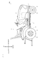
- FIG. 1 shows the tractor 100. In the figure, the front and rear direction and the upper and lower direction of the tractor 100 are indicated.
- the tractor 100 mainly includes a frame 1, an engine 2, a transmission 3, a front axle 4, and a rear axle 5.
- the tractor 100 also includes a cockpit 6, which accommodates an operator.
- the frame 1 serves as the main structure for the tractor 100.
- the engine 2 and the like described below are attached to the frame 1.
- the engine 2 converts energy obtained by burning a fuel into rotational movement.
- the engine 2 changes the driving state in accordance with the operation.
- the engine 2 maintains the rotational speed at a constant level even when the load changes.
- the transmission 3 switches between forward and backward movement of the tractor 100 and shifts the speed of the tractor 100.
- the transmission 3 includes a hydromechanical continuously variable transmission (HMT or I-HMT) as a transmission device.
- HMT hydromechanical continuously variable transmission
- the front axle 4 transmits the rotational energy from the engine 2 to front tires 41.
- the rotational energy from the engine 2 is input to the front axle 4 through the transmission 3.
- the front axle 4 is disposed next to a steering device. When the operator operates a handle, the steering device changes a steering angle of the front tires 41 in accordance with the operation.
- the rear axle 5 transmits the rotational energy from the engine 2 to rear tires 51.
- the rotational energy from the engine 2 is input to the rear axle 5 through the transmission 3.
- the rear axle 5 is provided with a PTO output mechanism.
- the PTO output mechanism inputs the rotational energy to a towing implement.
- the cockpit 6 is a control cabin of the tractor 100.
- the cockpit 6 is provided with an acceleration lever and a handle.
- the cockpit 6 is further provided with a forward pedal 71, a backward pedal 72, and a brake pedal 73. These pedals form the pedal assembly module 7.
- the pedal assembly module 7 is described below.
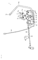
- FIG. 2 shows the pedal assembly module 7.
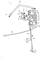
- FIG. 3 is a view in a direction of an arrow Fx in FIG. 2 .
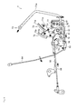
- FIG. 4 is a view in a direction of an arrow Fy in FIG. 2 .
- the front and rear direction, the left and right direction, and the upper and lower direction of the tractor 100 are indicated.
- the pedal assembly module 7 includes a link plate 74, as well as the forward pedal 71, the backward pedal 72, and the brake pedal 73.
- the forward pedal 71 includes an arm 71a, a sleeve 71s, and a pedal plate 71p.
- the arm 71 a is formed by bending a single plate member.
- the sleeve 71s is welded while being inserted in a hole of the arm 71a.
- the pedal plate 71p is welded on an end portion of the arm 71a.
- the pedal plate 71p is covered by a rubber plate as a slip stopper.
- a pin is disposed on a side surface of the arm 71a.
- a roller 81 is attached to the pin.
- Another pin is disposed on a side surface of the arm 71a.
- One end of a spring 82 is attached to the pin.
- the backward pedal 72 includes an arm 72a, a sleeve 72s, and a pedal plate 72p.
- the arm 72a is formed by bending a single plate member.
- the sleeve 72s is welded while being inserted in a hole of the arm 72a.
- the pedal plate 72p is welded on an end portion of the arm 72a.
- the pedal plate 72p is covered by a rubber plate as a slip stopper.
- a pin is disposed on a side surface of the arm 72a. One end of a connecting plate 83 is attached to the pin.
- the brake pedal 73 includes an arm 73a and a sleeve 73s.
- the arm 73a is formed by bending a single rod member.
- the sleeve 73s is welded while being in contact with an end portion of the arm 73a.
- the other end of the arm 73a is bent in the left and right direction, whereby a pedal portion (a portion serving as a substitute of a pedal plate) is formed.
- the pedal portion is covered by a rubber tube as a slip stopper.
- a clevis is disposed on a peripheral surface of the sleeve 73s.
- a brake rod 84 is attached to the clevis.
- the link plate 74 includes a cam plate 74c and a sleeve 74s.
- the cam plate 74c is cutout from a single plate member to be formed.
- the sleeve 74s is welded while being inserted in a hole of the cam plate 74c.
- the cam plate 74c is formed to have a predetermined curved surface (cam face) as its peripheral surface.
- the roller 81 described above is disposed while being in contact with the curved surface.
- the cam plate 74c is partly bent in the left and right direction, whereby a bracket portion is formed.
- the other end of the above-described spring 82 is attached to the bracket portion.
- a pin is disposed on a side surface of the cam plate 74c, and the other end of the connecting plate 83 is attached to the pin.
- the pedal assembly module 7 further includes a first shaft 75 and a second shaft 76.
- the first shaft 75 supports the forward pedal 71 and the backward pedal 72. Specifically, the forward pedal 71 and the backward pedal 72 are supported with the first shaft 75 inserted in their respective sleeves 71s and 72s. More specifically, the forward pedal 71 is fixed to the first shaft 75 by hitting a pin while the first shaft 75 is inserted in the sleeve 71s. The backward pedal 72 is supported by simply inserting the first shaft 75 in the sleeve 72s. Thus, the forward pedal 71 integrally rotates with the first shaft 75, whereas the backward pedal 72 rotates independently from the first shaft 75.
- One end of the first shaft 75 is provided with a clevis.
- a control rod 85 is attached to the clevis.
- the first shaft 75 has both ends supported by a frame box 77 formed by bending or welding a plate member.
- the second shaft 76 supports the brake pedal 73 and the link plate 74. Specifically, the brake pedal 73 and the link plate 74 are supported with the second shaft 76 inserted in their respective sleeves 73s and 74s. More specifically, the brake pedal 73 is supported by simply inserting the second shaft 76 in the sleeve 73s. The link plate 74 is supported by simply inserting the second shaft 76 in the sleeve 74s. Thus, the brake pedal 73 and the backward pedal 72 each rotate independently from the second shaft 76.
- a spring is fit on to an intermediate portion of the second shaft 76. The spring biases the brake pedal 73 (arm 73a).
- the second shaft 76 has both end portions supported by the frame box 77 described above.
- FIG. 5 shows the operation mode in the case where the forward pedal 71 is depressed. Arrows in the figure indicate operation directions of the components.
- the operator depresses the forward pedal 71 to move the tractor 100 forward. Then, the forward pedal 71 rotates the first shaft 75, and the first shaft 75 pulls the control rod 85. Thus, the operation state of the continuously variable transmission is changed, whereby the tractor 100 moves forward.
- the link plate 74 rotates along with the rotation of the forward pedal 71. Specifically, the roller 81 moves upward along with the rotation of the forward pedal 71. Thus, the link plate 74 in contact with the roller 81 also rotates. Thus, the link plate 74 rotates the backward pedal 72 through the connecting plate 83 (rotated in a direction opposite to that in a case where the backward pedal 72 is depressed). As described above, the pedal assembly module 7 pushes out the backward pedal 72 when the forward pedal 71 is depressed.
- FIG. 6 shows the operation mode where the backward pedal 72 is depressed. Arrows in the figure indicate operation directions of the components.
- the operator depresses the backward pedal 72 to move the tractor 100 backward. Then, the backward pedal 72 rotates the link plate 74 through the connecting plate 83, and the link plate 74 rotates the forward pedal 71. Specifically, the roller 81 moves downward along with the rotation of the link plate 74. Thus, the forward pedal 71, to which the roller 81 is attached, rotates (in a direction opposite to that in the case where the forward pedal 71 is depressed). As described above, the pedal assembly module 7 pushes out the forward pedal 71 when the backward pedal 72 is depressed.
- the first shaft 75 rotates along with the rotation of the forward pedal 71.
- the first shaft 75 pushes out the control rod 85.
- the operation state of the continuously variable transmission is changed, whereby the tractor 100 moves backward.
- FIG. 7 shows the operation mode in the case where the brake pedal 73 is depressed. Arrows in the figure indicate operation directions of the components.
- the operator depresses the brake pedal 73 to stop the tractor 100. Then, the brake pedal 73 pulls the brake rod 84. Thus, a braking device is activated and the tractor 100 is stopped.
- the pedal assembly module 7 further includes a parking brake mechanism.
- the parking brake mechanism mainly includes a ratchet plate 91 and a link rod 92.
- the ratchet plate 91 is cutout from a single plate member to be formed.
- the ratchet plate 91 includes a plurality of claw blades arranged along the arm 73a of the brake pedal 73.
- the ratchet plate 91 is supported by the frame box 77 in a rotatable manner.
- a lock plate 73r is welded on the arm 73a. The claws are hooked on the lock plate 73r.
- the link rod 92 is formed by bending a single rod member.
- the link rod 92 is coupled to the ratchet plate 91 having one end supported by the frame box 77.
- the link rod 92 can be regarded as being supported by the frame box 77.
- the link rod 92 has the other end coupled to the arm plate 93.
- a parking lever 94 is coupled to the arm plate 93.
- FIG. 8 shows the operation mode of the parking brake mechanism. Arrows in the figure indicate operation directions of the components.
- the operator moves the parking lever 94 to a predetermined position to park the tractor 100.
- the parking lever 94 pulls the link rod 92 through the arm plate 93.
- the link rod 92 rotates the ratchet plate 91.
- the brake pedal 73 is stopped.
- the braking device is kept under operation, and the tractor 100 can be parked.
- the pedal assembly module 7 according to the present invention described above is summarized as follows.
- the pedal assembly module 7 is formed by assembling and integrating the forward pedal 71, the backward pedal 72, and the brake pedal 73 with their functions ensured. Thus, the steps of attaching the various pedals can be omitted, and only the pedal assembly module 7 needs to be attached, whereby the productivity can be improved.
- the forward pedal 71 and the backward pedal 72 are supported with the first shaft 75 inserted in their sleeves 71s and 72s.
- a structure for supporting the forward pedal 71 and the backward pedal 72 is simplified, whereby the cost reduction is able to be achieved.
- the brake pedal 73 and the link plate 74 are supported with the second shaft 76 inserted in their sleeves 73s and 74s.
- a structure for supporting the brake pedal 73 and the link plate 74 is simplified, whereby the cost reduction is able to be achieved.
- the link plate 74 forms a mechanism of pushing out the backward pedal 72 when the forward pedal 71 is depressed, and pushing out the forward pedal 71 when the backward pedal 72 is depressed.
- the forward pedal 71 and the backward pedal 72 are interlocked, and the clutch is not needed.
- the cost reduction is able to be achieved.
- the ratchet plate 91 and the link rod 92 are supported by the frame box 77.
- the steps for attaching the ratchet plate 91 and the link rod 92 are able to be omitted, whereby the productivity is able to be further improved.
Landscapes
- Engineering & Computer Science (AREA)
- Physics & Mathematics (AREA)
- General Physics & Mathematics (AREA)
- Automation & Control Theory (AREA)
- Transportation (AREA)
- Mechanical Engineering (AREA)
- Mechanical Control Devices (AREA)
- Braking Elements And Transmission Devices (AREA)
Abstract
Description
- This invention relates pedal a pedal assembly module.
- Conventionally, tractors used for such as towing the working machine are known (See PTL 1). The tractor is equipped with a driver's seat and an operator operates on the seat. The tractor as described above is referred to as a riding type tractor.
- By the way, there are tractors equipped with a reverse pedal and the forward pedal (for example, refer to PTL 2). Such a tractor has at least three pedals disposed on the floor in conjunction with the brake pedal. Thus, the steps of attaching a variety of pedals are required, and there is a problem the process is complicated further. Therefore, the pedal assembly module which improves productivity has been desired.
-
- [PTL1]
JP 2013-52771 A - [PTL 2]
JP 2011-141016 A - The present invention is for proving a pedal assembly module to improve the productivity.
- The problem to be solved by the present invention is as described above and the following describes the means for solving this problem.
- The invention of the
claim 1 is a pedal assembly module comprising: - a forward pedal,
- a backward pedal,
- a first shaft supporting the forward pedal and the backward pedal,
- a brake pedal,
- a second shaft supporting the brake pedal, and
- a frame box supporting the first shaft and the second shaft,
- wherein the forward pedal, the backward pedal, and the brake pedal are assembled and integrated with their functions ensured.
- The invention of the
claim 2 is
the pedal assembly module according to theclaim 1 wherein: - the forward and the backward pedals are supported with the first shaft inserted in their each sleeve.
- The invention of the
claim 3 is
the pedal assembly module according to theclaim - a link plate rotates along with the rotation of the forward or the backward pedal,
- wherein the brake pedal and the link plate are supported with the second shaft inserted in their each sleeve.
- The invention of the
claim 4 is
the pedal assembly module according to theclaim 3 wherein: - the link plate forms a mechanism of pushing out the backward pedal when the forward pedal is depressed and of pushing out the forward pedal when the backward pedal is depressed.
- The invention of the
claim 5 is
the pedal assembly module according to any one ofclaims 1 to 4, further comprising: - a ratchet plate stopping the brake pedal, and
- a link rod able to rotate the ratchet plate,
- wherein the ratchet plate and the link rod are supported by the frame box.
- Advantageous effects of the invention are shown as follows.
- According to the
claim 1, the pedal assembly module is made by integrating and assembling the forward pedal, the backward pedal and the brake pedal with their functions ensured. This reduces some processes for installing various pedals, achieves just installing the pedal assembly and increases the productivity. - According to the
claim 2, the forward pedal and the back ward pedal are supported with inserting the first shaft to each sleeve. This makes simple in the structure for supporting the forward pedal and the backward pedal and achieves the cost reduction. - According to the
claim 3, the brake pedal and the link plate are supported with inserting the second shaft to each sleeve. This makes simple in the structure for supporting the brake pedal and the link plate and achieves the cost reduction. - According to the
claim 4, the link plate forms a mechanism of pushing out the backward pedal when the forward pedal is depressed and of pushing out the forward pedal when the backward pedal is depressed. This makes the forward pedal and the backward pedal to work together, reduces a clutch and achieves the cost reduction. - According to the
claim 5, the ratchet plate and the link rod are supported by the frame box. This reduces some processes for installing and further increases the productivity. -
-
FIG. 1 is a diagram showing a tractor. -
FIG. 2 is a diagram showing a pedal assembly module. -
FIG. 3 is a view in a direction of an arrow Fx inFIG. 2 . -
FIG. 4 is a view in a direction of an arrow Fy inFIG. 2 . -
FIG. 5 is a diagram showing an operation mode in a case where a forward pedal is depressed. -
FIG. 6 is a diagram showing an operation mode in a case where a backward pedal is depressed. -
FIG. 7 is a diagram showing an operation mode in a case where a brake pedal is depressed. -
FIG. 8 is a diagram showing an operation mode of a parking brake mechanism. - First, a
tractor 100 is briefly described. Apedal assembly module 7 according to the present invention can be applied to vehicles other than tractors. -
FIG. 1 shows thetractor 100. In the figure, the front and rear direction and the upper and lower direction of thetractor 100 are indicated. - The
tractor 100 mainly includes aframe 1, anengine 2, atransmission 3, afront axle 4, and arear axle 5. Thetractor 100 also includes acockpit 6, which accommodates an operator. - The
frame 1 serves as the main structure for thetractor 100. Theengine 2 and the like described below are attached to theframe 1. - The
engine 2 converts energy obtained by burning a fuel into rotational movement. When the operator operates an acceleration lever, theengine 2 changes the driving state in accordance with the operation. Theengine 2 maintains the rotational speed at a constant level even when the load changes. - The
transmission 3 switches between forward and backward movement of thetractor 100 and shifts the speed of thetractor 100. When the operator operates a shift lever, the operation state of thetransmission 3 changes in accordance with the operation. Thetransmission 3 includes a hydromechanical continuously variable transmission (HMT or I-HMT) as a transmission device. - The
front axle 4 transmits the rotational energy from theengine 2 tofront tires 41. The rotational energy from theengine 2 is input to thefront axle 4 through thetransmission 3. Thefront axle 4 is disposed next to a steering device. When the operator operates a handle, the steering device changes a steering angle of thefront tires 41 in accordance with the operation. - The
rear axle 5 transmits the rotational energy from theengine 2 torear tires 51. The rotational energy from theengine 2 is input to therear axle 5 through thetransmission 3. Therear axle 5 is provided with a PTO output mechanism. The PTO output mechanism inputs the rotational energy to a towing implement. - The
cockpit 6 is a control cabin of thetractor 100. Thecockpit 6 is provided with an acceleration lever and a handle. Thecockpit 6 is further provided with aforward pedal 71, abackward pedal 72, and abrake pedal 73. These pedals form thepedal assembly module 7. - The
pedal assembly module 7 is described below. -
FIG. 2 shows thepedal assembly module 7.FIG. 3 is a view in a direction of an arrow Fx inFIG. 2 .FIG. 4 is a view in a direction of an arrow Fy inFIG. 2 . In the figure, the front and rear direction, the left and right direction, and the upper and lower direction of thetractor 100 are indicated. - The
pedal assembly module 7 includes alink plate 74, as well as theforward pedal 71, thebackward pedal 72, and thebrake pedal 73. - The
forward pedal 71 includes anarm 71a, asleeve 71s, and apedal plate 71p. Thearm 71 a is formed by bending a single plate member. Thesleeve 71s is welded while being inserted in a hole of thearm 71a. Thepedal plate 71p is welded on an end portion of thearm 71a. Thepedal plate 71p is covered by a rubber plate as a slip stopper. A pin is disposed on a side surface of thearm 71a. Aroller 81 is attached to the pin. Another pin is disposed on a side surface of thearm 71a. One end of aspring 82 is attached to the pin. - The
backward pedal 72 includes anarm 72a, asleeve 72s, and apedal plate 72p. Thearm 72a is formed by bending a single plate member. Thesleeve 72s is welded while being inserted in a hole of thearm 72a. Thepedal plate 72p is welded on an end portion of thearm 72a. Thepedal plate 72p is covered by a rubber plate as a slip stopper. A pin is disposed on a side surface of thearm 72a. One end of a connectingplate 83 is attached to the pin. - The
brake pedal 73 includes anarm 73a and asleeve 73s. Thearm 73a is formed by bending a single rod member. Thesleeve 73s is welded while being in contact with an end portion of thearm 73a. The other end of thearm 73a is bent in the left and right direction, whereby a pedal portion (a portion serving as a substitute of a pedal plate) is formed. The pedal portion is covered by a rubber tube as a slip stopper. A clevis is disposed on a peripheral surface of thesleeve 73s. Abrake rod 84 is attached to the clevis. - The
link plate 74 includes acam plate 74c and asleeve 74s. Thecam plate 74c is cutout from a single plate member to be formed. Thesleeve 74s is welded while being inserted in a hole of thecam plate 74c. Thecam plate 74c is formed to have a predetermined curved surface (cam face) as its peripheral surface. Theroller 81 described above is disposed while being in contact with the curved surface. Thecam plate 74c is partly bent in the left and right direction, whereby a bracket portion is formed. The other end of the above-describedspring 82 is attached to the bracket portion. A pin is disposed on a side surface of thecam plate 74c, and the other end of the connectingplate 83 is attached to the pin. - The
pedal assembly module 7 further includes afirst shaft 75 and asecond shaft 76. - The
first shaft 75 supports theforward pedal 71 and thebackward pedal 72. Specifically, theforward pedal 71 and thebackward pedal 72 are supported with thefirst shaft 75 inserted in theirrespective sleeves forward pedal 71 is fixed to thefirst shaft 75 by hitting a pin while thefirst shaft 75 is inserted in thesleeve 71s. Thebackward pedal 72 is supported by simply inserting thefirst shaft 75 in thesleeve 72s. Thus, theforward pedal 71 integrally rotates with thefirst shaft 75, whereas thebackward pedal 72 rotates independently from thefirst shaft 75. One end of thefirst shaft 75 is provided with a clevis. Acontrol rod 85 is attached to the clevis. Thefirst shaft 75 has both ends supported by aframe box 77 formed by bending or welding a plate member. - The
second shaft 76 supports thebrake pedal 73 and thelink plate 74. Specifically, thebrake pedal 73 and thelink plate 74 are supported with thesecond shaft 76 inserted in theirrespective sleeves brake pedal 73 is supported by simply inserting thesecond shaft 76 in thesleeve 73s. Thelink plate 74 is supported by simply inserting thesecond shaft 76 in thesleeve 74s. Thus, thebrake pedal 73 and thebackward pedal 72 each rotate independently from thesecond shaft 76. A spring is fit on to an intermediate portion of thesecond shaft 76. The spring biases the brake pedal 73 (arm 73a). Thesecond shaft 76 has both end portions supported by theframe box 77 described above. - Next, an operation mode in a case where the
forward pedal 71 is depressed will be described. -
FIG. 5 shows the operation mode in the case where theforward pedal 71 is depressed. Arrows in the figure indicate operation directions of the components. - The operator depresses the
forward pedal 71 to move thetractor 100 forward. Then, theforward pedal 71 rotates thefirst shaft 75, and thefirst shaft 75 pulls thecontrol rod 85. Thus, the operation state of the continuously variable transmission is changed, whereby thetractor 100 moves forward. - Here, the
link plate 74 rotates along with the rotation of theforward pedal 71. Specifically, theroller 81 moves upward along with the rotation of theforward pedal 71. Thus, thelink plate 74 in contact with theroller 81 also rotates. Thus, thelink plate 74 rotates thebackward pedal 72 through the connecting plate 83 (rotated in a direction opposite to that in a case where thebackward pedal 72 is depressed). As described above, thepedal assembly module 7 pushes out thebackward pedal 72 when theforward pedal 71 is depressed. - Next, an operation mode in the case where the
backward pedal 72 is depressed will be described. -
FIG. 6 shows the operation mode where thebackward pedal 72 is depressed. Arrows in the figure indicate operation directions of the components. - The operator depresses the
backward pedal 72 to move thetractor 100 backward. Then, thebackward pedal 72 rotates thelink plate 74 through the connectingplate 83, and thelink plate 74 rotates theforward pedal 71. Specifically, theroller 81 moves downward along with the rotation of thelink plate 74. Thus, theforward pedal 71, to which theroller 81 is attached, rotates (in a direction opposite to that in the case where theforward pedal 71 is depressed). As described above, thepedal assembly module 7 pushes out theforward pedal 71 when thebackward pedal 72 is depressed. - Here, the
first shaft 75 rotates along with the rotation of theforward pedal 71. Thus, thefirst shaft 75 pushes out thecontrol rod 85. Thus, the operation state of the continuously variable transmission is changed, whereby thetractor 100 moves backward. - Next, an operation mode in a case where the
brake pedal 73 is depressed will be described. -
FIG. 7 shows the operation mode in the case where thebrake pedal 73 is depressed. Arrows in the figure indicate operation directions of the components. - The operator depresses the
brake pedal 73 to stop thetractor 100. Then, thebrake pedal 73 pulls thebrake rod 84. Thus, a braking device is activated and thetractor 100 is stopped. - The
pedal assembly module 7 further includes a parking brake mechanism. - The parking brake mechanism mainly includes a
ratchet plate 91 and alink rod 92. - The
ratchet plate 91 is cutout from a single plate member to be formed. Theratchet plate 91 includes a plurality of claw blades arranged along thearm 73a of thebrake pedal 73. Theratchet plate 91 is supported by theframe box 77 in a rotatable manner. Alock plate 73r is welded on thearm 73a. The claws are hooked on thelock plate 73r. - The
link rod 92 is formed by bending a single rod member. Thelink rod 92 is coupled to theratchet plate 91 having one end supported by theframe box 77. Thus, thelink rod 92 can be regarded as being supported by theframe box 77. Thelink rod 92 has the other end coupled to thearm plate 93. Aparking lever 94 is coupled to thearm plate 93. - Next, an operation mode of the parking brake mechanism will be described.
-
FIG. 8 shows the operation mode of the parking brake mechanism. Arrows in the figure indicate operation directions of the components. - The operator moves the
parking lever 94 to a predetermined position to park thetractor 100. Thus, theparking lever 94 pulls thelink rod 92 through thearm plate 93. Thelink rod 92 rotates theratchet plate 91. Then, when the operator depresses thebrake pedal 73, the claws of theratchet plate 91 are hooked on thelock plate 73r. Thus, thebrake pedal 73 is stopped. Thus, the braking device is kept under operation, and thetractor 100 can be parked. - The
pedal assembly module 7 according to the present invention described above is summarized as follows. - The
pedal assembly module 7 is formed by assembling and integrating theforward pedal 71, thebackward pedal 72, and thebrake pedal 73 with their functions ensured. Thus, the steps of attaching the various pedals can be omitted, and only thepedal assembly module 7 needs to be attached, whereby the productivity can be improved. - As a feature of the
pedal assembly module 7, theforward pedal 71 and thebackward pedal 72 are supported with thefirst shaft 75 inserted in theirsleeves forward pedal 71 and thebackward pedal 72 is simplified, whereby the cost reduction is able to be achieved. - As a feature of the
pedal assembly module 7, thebrake pedal 73 and thelink plate 74 are supported with thesecond shaft 76 inserted in theirsleeves brake pedal 73 and thelink plate 74 is simplified, whereby the cost reduction is able to be achieved. - Furthermore, as a feature of the
pedal assembly module 7, thelink plate 74 forms a mechanism of pushing out thebackward pedal 72 when theforward pedal 71 is depressed, and pushing out theforward pedal 71 when thebackward pedal 72 is depressed. Thus, theforward pedal 71 and thebackward pedal 72 are interlocked, and the clutch is not needed. Thus, the cost reduction is able to be achieved. - Still furthermore, as a feature of the
pedal assembly module 7, theratchet plate 91 and thelink rod 92 are supported by theframe box 77. Thus, the steps for attaching theratchet plate 91 and thelink rod 92 are able to be omitted, whereby the productivity is able to be further improved.
Claims (6)
- A pedal assembly module comprising:a forward pedal,a backward pedal,a first shaft supporting the forward pedal and the backward pedal,a brake pedal,a second shaft supporting the brake pedal, anda frame box supporting the first shaft and the second shaft,wherein the forward pedal, the backward pedal, and the brake pedal are assembled and integrated with their functions ensured.
- The pedal assembly module according to the claim 1 wherein:the forward and the backward pedals are supported with the first shaft inserted in their each sleeve.
- The pedal assembly module according to the claim 1 or 2, further comprising:a link plate rotates along with the rotation of the forward or the backward pedal,wherein the brake pedal and the link plate are supported with the second shaft inserted in their each sleeve.
- The pedal assembly module according to the claim 3 wherein:the link plate forms a mechanism of pushing out the backward pedal when the forward pedal is depressed and of pushing out the forward pedal when the backward pedal is depressed.
- The pedal assembly module according to any one of claims 1, 2 and 4, further comprising:a ratchet plate stopping the brake pedal, anda link rod able to rotate the ratchet plate,wherein the ratchet plate and the link rod are supported by the frame box.
- The pedal assembly module according to the claim 3, further comprising:a ratchet plate stopping the brake pedal, anda link rod able to rotate the ratchet plate,wherein the ratchet plate and the link rod are supported by the frame box.
Applications Claiming Priority (2)
| Application Number | Priority Date | Filing Date | Title |
|---|---|---|---|
| US201361892582P | 2013-10-18 | 2013-10-18 | |
| US14/319,959 US9317058B2 (en) | 2013-10-18 | 2014-06-30 | Pedal assembly module |
Publications (2)
| Publication Number | Publication Date |
|---|---|
| EP2862759A1 true EP2862759A1 (en) | 2015-04-22 |
| EP2862759B1 EP2862759B1 (en) | 2019-04-10 |
Family
ID=51690917
Family Applications (1)
| Application Number | Title | Priority Date | Filing Date |
|---|---|---|---|
| EP14188636.6A Active EP2862759B1 (en) | 2013-10-18 | 2014-10-13 | Pedal assembly module |
Country Status (2)
| Country | Link |
|---|---|
| US (1) | US9317058B2 (en) |
| EP (1) | EP2862759B1 (en) |
Families Citing this family (2)
| Publication number | Priority date | Publication date | Assignee | Title |
|---|---|---|---|---|
| US11175688B2 (en) * | 2019-05-28 | 2021-11-16 | Hyster-Yale Group, Inc. | Reciprocating pedals with dual-levered cam for asymmetric reciprocation |
| JP7031652B2 (en) * | 2019-12-26 | 2022-03-08 | 井関農機株式会社 | Work vehicle |
Citations (12)
| Publication number | Priority date | Publication date | Assignee | Title |
|---|---|---|---|---|
| DE1817849A1 (en) * | 1967-10-30 | 1972-08-31 | Linde Ag | Control device for a continuously variable transmission of a drive unit, in particular a motor vehicle |
| US4014218A (en) * | 1975-06-30 | 1977-03-29 | Brandt Manufacturing Co. | Apparatus for transmission-throttle control |
| FR2395857A1 (en) * | 1977-06-29 | 1979-01-26 | Massey Ferguson Inc | PEDAL CONTROL OF TRANSMISSION AND ENGINE ACCELERATION IN A VEHICLE |
| US4519270A (en) * | 1981-11-16 | 1985-05-28 | Toyota Jidosha Kabushiki Kaisha | Foot-operated control device for parking brake |
| JPH0268228A (en) * | 1988-08-31 | 1990-03-07 | Iseki & Co Ltd | Running pedal for tractor and the like |
| US5022477A (en) * | 1986-08-27 | 1991-06-11 | Deere & Company | System and method for controlling the ground speed and enhancing the maneuverability of an off-road vehicle |
| US5048638A (en) * | 1988-09-17 | 1991-09-17 | Deere & Company | System for controlling the ground speed and direction of travel of an off-road vehicle |
| GB2309287A (en) * | 1996-01-16 | 1997-07-23 | Jungheinrich Ag | A pedal control for a vehicle |
| JP2011141016A (en) | 2010-01-08 | 2011-07-21 | Yanmar Co Ltd | Working vehicle |
| WO2012104871A1 (en) * | 2011-01-31 | 2012-08-09 | Mahindra & Mahindra Ltd. | An operating mechanism for motion control and cruise control in an off-road vehicle operating on hydrostatic transmission |
| EP2537722A2 (en) * | 2011-06-21 | 2012-12-26 | Iseki & Co., Ltd. | Parking lock mechanism and working vehicle |
| JP2013052771A (en) | 2011-09-05 | 2013-03-21 | Yanmar Co Ltd | Agricultural tractor |
Family Cites Families (6)
| Publication number | Priority date | Publication date | Assignee | Title |
|---|---|---|---|---|
| US3954146A (en) * | 1974-04-26 | 1976-05-04 | Deere & Company | Transmission control linkage |
| US4106362A (en) * | 1977-02-14 | 1978-08-15 | Towmotor Corporation | Control linkage for torque converter transmission or the like |
| US5216935A (en) * | 1988-12-16 | 1993-06-08 | Kubota Ltd. | Bidirectional control arrangement for vehicle |
| JP2648262B2 (en) * | 1991-12-10 | 1997-08-27 | 株式会社クボタ | Shifting structure of work vehicle |
| US6886677B2 (en) * | 2002-10-18 | 2005-05-03 | Deere & Co. | Interlock of parking brake and drive control pedals for utility vehicle |
| US6904985B2 (en) * | 2003-05-21 | 2005-06-14 | Deere & Company | Transmission control device for vehicles and steering assembly for vehicles |
-
2014
- 2014-06-30 US US14/319,959 patent/US9317058B2/en active Active
- 2014-10-13 EP EP14188636.6A patent/EP2862759B1/en active Active
Patent Citations (12)
| Publication number | Priority date | Publication date | Assignee | Title |
|---|---|---|---|---|
| DE1817849A1 (en) * | 1967-10-30 | 1972-08-31 | Linde Ag | Control device for a continuously variable transmission of a drive unit, in particular a motor vehicle |
| US4014218A (en) * | 1975-06-30 | 1977-03-29 | Brandt Manufacturing Co. | Apparatus for transmission-throttle control |
| FR2395857A1 (en) * | 1977-06-29 | 1979-01-26 | Massey Ferguson Inc | PEDAL CONTROL OF TRANSMISSION AND ENGINE ACCELERATION IN A VEHICLE |
| US4519270A (en) * | 1981-11-16 | 1985-05-28 | Toyota Jidosha Kabushiki Kaisha | Foot-operated control device for parking brake |
| US5022477A (en) * | 1986-08-27 | 1991-06-11 | Deere & Company | System and method for controlling the ground speed and enhancing the maneuverability of an off-road vehicle |
| JPH0268228A (en) * | 1988-08-31 | 1990-03-07 | Iseki & Co Ltd | Running pedal for tractor and the like |
| US5048638A (en) * | 1988-09-17 | 1991-09-17 | Deere & Company | System for controlling the ground speed and direction of travel of an off-road vehicle |
| GB2309287A (en) * | 1996-01-16 | 1997-07-23 | Jungheinrich Ag | A pedal control for a vehicle |
| JP2011141016A (en) | 2010-01-08 | 2011-07-21 | Yanmar Co Ltd | Working vehicle |
| WO2012104871A1 (en) * | 2011-01-31 | 2012-08-09 | Mahindra & Mahindra Ltd. | An operating mechanism for motion control and cruise control in an off-road vehicle operating on hydrostatic transmission |
| EP2537722A2 (en) * | 2011-06-21 | 2012-12-26 | Iseki & Co., Ltd. | Parking lock mechanism and working vehicle |
| JP2013052771A (en) | 2011-09-05 | 2013-03-21 | Yanmar Co Ltd | Agricultural tractor |
Also Published As
| Publication number | Publication date |
|---|---|
| US9317058B2 (en) | 2016-04-19 |
| US20150107394A1 (en) | 2015-04-23 |
| EP2862759B1 (en) | 2019-04-10 |
Similar Documents
| Publication | Publication Date | Title |
|---|---|---|
| EP3421283B1 (en) | Work vehicle | |
| EP3195717B1 (en) | Work vehicle | |
| EP2862759B1 (en) | Pedal assembly module | |
| JP2023035424A (en) | work vehicle | |
| EP3896551B1 (en) | Vehicular operation pedal device | |
| KR100825529B1 (en) | Shift operation structure of work car | |
| WO2013186953A1 (en) | Vehicle | |
| EP4279768A1 (en) | Work vehicle | |
| JP5497602B2 (en) | Transplanter | |
| EP2537722A2 (en) | Parking lock mechanism and working vehicle | |
| JP5337113B2 (en) | Tractor | |
| JP2020201825A (en) | Operation pedal unit for vehicles | |
| JP2009190616A (en) | Brake operation mechanism of tractor | |
| JP2010195095A (en) | Working vehicle | |
| JP2015044552A (en) | Tractor | |
| JP2001097191A (en) | Vehicle pedal release structure | |
| JP4563014B2 (en) | Agricultural machine | |
| JP6374766B2 (en) | Work vehicle | |
| JP2003310004A (en) | Riding rice transplanter | |
| JP4009785B2 (en) | Combine | |
| JP3370114B2 (en) | Work vehicle turning operation structure | |
| JP2009190615A (en) | Brake lamp lighting operation structure in tractor | |
| JPH053378Y2 (en) | ||
| JP2587616Y2 (en) | Passenger work vehicle braking device | |
| JP2023037146A (en) | Control device of work vehicle |
Legal Events
| Date | Code | Title | Description |
|---|---|---|---|
| PUAI | Public reference made under article 153(3) epc to a published international application that has entered the european phase |
Free format text: ORIGINAL CODE: 0009012 |
|
| 17P | Request for examination filed |
Effective date: 20141013 |
|
| AK | Designated contracting states |
Kind code of ref document: A1 Designated state(s): AL AT BE BG CH CY CZ DE DK EE ES FI FR GB GR HR HU IE IS IT LI LT LU LV MC MK MT NL NO PL PT RO RS SE SI SK SM TR |
|
| AX | Request for extension of the european patent |
Extension state: BA ME |
|
| R17P | Request for examination filed (corrected) |
Effective date: 20151022 |
|
| RBV | Designated contracting states (corrected) |
Designated state(s): AL AT BE BG CH CY CZ DE DK EE ES FI FR GB GR HR HU IE IS IT LI LT LU LV MC MK MT NL NO PL PT RO RS SE SI SK SM TR |
|
| GRAP | Despatch of communication of intention to grant a patent |
Free format text: ORIGINAL CODE: EPIDOSNIGR1 |
|
| STAA | Information on the status of an ep patent application or granted ep patent |
Free format text: STATUS: GRANT OF PATENT IS INTENDED |
|
| INTG | Intention to grant announced |
Effective date: 20181023 |
|
| RIN1 | Information on inventor provided before grant (corrected) |
Inventor name: IIDA, KEISUKE Inventor name: GOTO, TAKASHI Inventor name: HANAFUSA, MASAHIRO |
|
| RIC1 | Information provided on ipc code assigned before grant |
Ipc: G05G 1/08 20060101ALI20150212BHEP Ipc: G05G 1/30 20080401ALI20150212BHEP Ipc: B60T 7/06 20060101AFI20150212BHEP Ipc: G05G 1/36 20080401ALI20150212BHEP |
|
| GRAS | Grant fee paid |
Free format text: ORIGINAL CODE: EPIDOSNIGR3 |
|
| GRAA | (expected) grant |
Free format text: ORIGINAL CODE: 0009210 |
|
| STAA | Information on the status of an ep patent application or granted ep patent |
Free format text: STATUS: THE PATENT HAS BEEN GRANTED |
|
| AK | Designated contracting states |
Kind code of ref document: B1 Designated state(s): AL AT BE BG CH CY CZ DE DK EE ES FI FR GB GR HR HU IE IS IT LI LT LU LV MC MK MT NL NO PL PT RO RS SE SI SK SM TR |
|
| REG | Reference to a national code |
Ref country code: GB Ref legal event code: FG4D |
|
| REG | Reference to a national code |
Ref country code: CH Ref legal event code: EP Ref country code: AT Ref legal event code: REF Ref document number: 1118242 Country of ref document: AT Kind code of ref document: T Effective date: 20190415 |
|
| REG | Reference to a national code |
Ref country code: IE Ref legal event code: FG4D |
|
| REG | Reference to a national code |
Ref country code: DE Ref legal event code: R096 Ref document number: 602014044340 Country of ref document: DE |
|
| REG | Reference to a national code |
Ref country code: NL Ref legal event code: MP Effective date: 20190410 |
|
| REG | Reference to a national code |
Ref country code: LT Ref legal event code: MG4D |
|
| REG | Reference to a national code |
Ref country code: AT Ref legal event code: MK05 Ref document number: 1118242 Country of ref document: AT Kind code of ref document: T Effective date: 20190410 |
|
| PG25 | Lapsed in a contracting state [announced via postgrant information from national office to epo] |
Ref country code: NL Free format text: LAPSE BECAUSE OF FAILURE TO SUBMIT A TRANSLATION OF THE DESCRIPTION OR TO PAY THE FEE WITHIN THE PRESCRIBED TIME-LIMIT Effective date: 20190410 |
|
| PG25 | Lapsed in a contracting state [announced via postgrant information from national office to epo] |
Ref country code: FI Free format text: LAPSE BECAUSE OF FAILURE TO SUBMIT A TRANSLATION OF THE DESCRIPTION OR TO PAY THE FEE WITHIN THE PRESCRIBED TIME-LIMIT Effective date: 20190410 Ref country code: SE Free format text: LAPSE BECAUSE OF FAILURE TO SUBMIT A TRANSLATION OF THE DESCRIPTION OR TO PAY THE FEE WITHIN THE PRESCRIBED TIME-LIMIT Effective date: 20190410 Ref country code: ES Free format text: LAPSE BECAUSE OF FAILURE TO SUBMIT A TRANSLATION OF THE DESCRIPTION OR TO PAY THE FEE WITHIN THE PRESCRIBED TIME-LIMIT Effective date: 20190410 Ref country code: LT Free format text: LAPSE BECAUSE OF FAILURE TO SUBMIT A TRANSLATION OF THE DESCRIPTION OR TO PAY THE FEE WITHIN THE PRESCRIBED TIME-LIMIT Effective date: 20190410 Ref country code: PT Free format text: LAPSE BECAUSE OF FAILURE TO SUBMIT A TRANSLATION OF THE DESCRIPTION OR TO PAY THE FEE WITHIN THE PRESCRIBED TIME-LIMIT Effective date: 20190910 Ref country code: AL Free format text: LAPSE BECAUSE OF FAILURE TO SUBMIT A TRANSLATION OF THE DESCRIPTION OR TO PAY THE FEE WITHIN THE PRESCRIBED TIME-LIMIT Effective date: 20190410 Ref country code: NO Free format text: LAPSE BECAUSE OF FAILURE TO SUBMIT A TRANSLATION OF THE DESCRIPTION OR TO PAY THE FEE WITHIN THE PRESCRIBED TIME-LIMIT Effective date: 20190710 Ref country code: HR Free format text: LAPSE BECAUSE OF FAILURE TO SUBMIT A TRANSLATION OF THE DESCRIPTION OR TO PAY THE FEE WITHIN THE PRESCRIBED TIME-LIMIT Effective date: 20190410 |
|
| PG25 | Lapsed in a contracting state [announced via postgrant information from national office to epo] |
Ref country code: PL Free format text: LAPSE BECAUSE OF FAILURE TO SUBMIT A TRANSLATION OF THE DESCRIPTION OR TO PAY THE FEE WITHIN THE PRESCRIBED TIME-LIMIT Effective date: 20190410 Ref country code: GR Free format text: LAPSE BECAUSE OF FAILURE TO SUBMIT A TRANSLATION OF THE DESCRIPTION OR TO PAY THE FEE WITHIN THE PRESCRIBED TIME-LIMIT Effective date: 20190711 Ref country code: LV Free format text: LAPSE BECAUSE OF FAILURE TO SUBMIT A TRANSLATION OF THE DESCRIPTION OR TO PAY THE FEE WITHIN THE PRESCRIBED TIME-LIMIT Effective date: 20190410 Ref country code: RS Free format text: LAPSE BECAUSE OF FAILURE TO SUBMIT A TRANSLATION OF THE DESCRIPTION OR TO PAY THE FEE WITHIN THE PRESCRIBED TIME-LIMIT Effective date: 20190410 Ref country code: BG Free format text: LAPSE BECAUSE OF FAILURE TO SUBMIT A TRANSLATION OF THE DESCRIPTION OR TO PAY THE FEE WITHIN THE PRESCRIBED TIME-LIMIT Effective date: 20190710 |
|
| PG25 | Lapsed in a contracting state [announced via postgrant information from national office to epo] |
Ref country code: AT Free format text: LAPSE BECAUSE OF FAILURE TO SUBMIT A TRANSLATION OF THE DESCRIPTION OR TO PAY THE FEE WITHIN THE PRESCRIBED TIME-LIMIT Effective date: 20190410 Ref country code: IS Free format text: LAPSE BECAUSE OF FAILURE TO SUBMIT A TRANSLATION OF THE DESCRIPTION OR TO PAY THE FEE WITHIN THE PRESCRIBED TIME-LIMIT Effective date: 20190810 |
|
| REG | Reference to a national code |
Ref country code: DE Ref legal event code: R097 Ref document number: 602014044340 Country of ref document: DE |
|
| PG25 | Lapsed in a contracting state [announced via postgrant information from national office to epo] |
Ref country code: RO Free format text: LAPSE BECAUSE OF FAILURE TO SUBMIT A TRANSLATION OF THE DESCRIPTION OR TO PAY THE FEE WITHIN THE PRESCRIBED TIME-LIMIT Effective date: 20190410 Ref country code: CZ Free format text: LAPSE BECAUSE OF FAILURE TO SUBMIT A TRANSLATION OF THE DESCRIPTION OR TO PAY THE FEE WITHIN THE PRESCRIBED TIME-LIMIT Effective date: 20190410 Ref country code: DK Free format text: LAPSE BECAUSE OF FAILURE TO SUBMIT A TRANSLATION OF THE DESCRIPTION OR TO PAY THE FEE WITHIN THE PRESCRIBED TIME-LIMIT Effective date: 20190410 Ref country code: EE Free format text: LAPSE BECAUSE OF FAILURE TO SUBMIT A TRANSLATION OF THE DESCRIPTION OR TO PAY THE FEE WITHIN THE PRESCRIBED TIME-LIMIT Effective date: 20190410 Ref country code: SK Free format text: LAPSE BECAUSE OF FAILURE TO SUBMIT A TRANSLATION OF THE DESCRIPTION OR TO PAY THE FEE WITHIN THE PRESCRIBED TIME-LIMIT Effective date: 20190410 |
|
| PLBE | No opposition filed within time limit |
Free format text: ORIGINAL CODE: 0009261 |
|
| STAA | Information on the status of an ep patent application or granted ep patent |
Free format text: STATUS: NO OPPOSITION FILED WITHIN TIME LIMIT |
|
| PG25 | Lapsed in a contracting state [announced via postgrant information from national office to epo] |
Ref country code: IT Free format text: LAPSE BECAUSE OF FAILURE TO SUBMIT A TRANSLATION OF THE DESCRIPTION OR TO PAY THE FEE WITHIN THE PRESCRIBED TIME-LIMIT Effective date: 20190410 Ref country code: SM Free format text: LAPSE BECAUSE OF FAILURE TO SUBMIT A TRANSLATION OF THE DESCRIPTION OR TO PAY THE FEE WITHIN THE PRESCRIBED TIME-LIMIT Effective date: 20190410 |
|
| 26N | No opposition filed |
Effective date: 20200113 |
|
| PG25 | Lapsed in a contracting state [announced via postgrant information from national office to epo] |
Ref country code: TR Free format text: LAPSE BECAUSE OF FAILURE TO SUBMIT A TRANSLATION OF THE DESCRIPTION OR TO PAY THE FEE WITHIN THE PRESCRIBED TIME-LIMIT Effective date: 20190410 |
|
| PG25 | Lapsed in a contracting state [announced via postgrant information from national office to epo] |
Ref country code: SI Free format text: LAPSE BECAUSE OF FAILURE TO SUBMIT A TRANSLATION OF THE DESCRIPTION OR TO PAY THE FEE WITHIN THE PRESCRIBED TIME-LIMIT Effective date: 20190410 Ref country code: MC Free format text: LAPSE BECAUSE OF FAILURE TO SUBMIT A TRANSLATION OF THE DESCRIPTION OR TO PAY THE FEE WITHIN THE PRESCRIBED TIME-LIMIT Effective date: 20190410 |
|
| REG | Reference to a national code |
Ref country code: CH Ref legal event code: PL |
|
| PG25 | Lapsed in a contracting state [announced via postgrant information from national office to epo] |
Ref country code: LU Free format text: LAPSE BECAUSE OF NON-PAYMENT OF DUE FEES Effective date: 20191013 Ref country code: CH Free format text: LAPSE BECAUSE OF NON-PAYMENT OF DUE FEES Effective date: 20191031 Ref country code: LI Free format text: LAPSE BECAUSE OF NON-PAYMENT OF DUE FEES Effective date: 20191031 |
|
| REG | Reference to a national code |
Ref country code: BE Ref legal event code: MM Effective date: 20191031 |
|
| PG25 | Lapsed in a contracting state [announced via postgrant information from national office to epo] |
Ref country code: BE Free format text: LAPSE BECAUSE OF NON-PAYMENT OF DUE FEES Effective date: 20191031 |
|
| REG | Reference to a national code |
Ref country code: DE Ref legal event code: R082 Ref document number: 602014044340 Country of ref document: DE Representative=s name: JOSTARNDT PATENTANWALTS-AG, DE Ref country code: DE Ref legal event code: R081 Ref document number: 602014044340 Country of ref document: DE Owner name: YANMAR POWER TECHNOLOGY CO., LTD., JP Free format text: FORMER OWNER: YANMAR CO., LTD., OSAKA-SHI, JP |
|
| PG25 | Lapsed in a contracting state [announced via postgrant information from national office to epo] |
Ref country code: IE Free format text: LAPSE BECAUSE OF NON-PAYMENT OF DUE FEES Effective date: 20191013 |
|
| PG25 | Lapsed in a contracting state [announced via postgrant information from national office to epo] |
Ref country code: CY Free format text: LAPSE BECAUSE OF FAILURE TO SUBMIT A TRANSLATION OF THE DESCRIPTION OR TO PAY THE FEE WITHIN THE PRESCRIBED TIME-LIMIT Effective date: 20190410 |
|
| PG25 | Lapsed in a contracting state [announced via postgrant information from national office to epo] |
Ref country code: MT Free format text: LAPSE BECAUSE OF FAILURE TO SUBMIT A TRANSLATION OF THE DESCRIPTION OR TO PAY THE FEE WITHIN THE PRESCRIBED TIME-LIMIT Effective date: 20190410 Ref country code: HU Free format text: LAPSE BECAUSE OF FAILURE TO SUBMIT A TRANSLATION OF THE DESCRIPTION OR TO PAY THE FEE WITHIN THE PRESCRIBED TIME-LIMIT; INVALID AB INITIO Effective date: 20141013 |
|
| PG25 | Lapsed in a contracting state [announced via postgrant information from national office to epo] |
Ref country code: MK Free format text: LAPSE BECAUSE OF FAILURE TO SUBMIT A TRANSLATION OF THE DESCRIPTION OR TO PAY THE FEE WITHIN THE PRESCRIBED TIME-LIMIT Effective date: 20190410 |
|
| PGFP | Annual fee paid to national office [announced via postgrant information from national office to epo] |
Ref country code: GB Payment date: 20221020 Year of fee payment: 9 |
|
| GBPC | Gb: european patent ceased through non-payment of renewal fee |
Effective date: 20231013 |
|
| PG25 | Lapsed in a contracting state [announced via postgrant information from national office to epo] |
Ref country code: GB Free format text: LAPSE BECAUSE OF NON-PAYMENT OF DUE FEES Effective date: 20231013 |
|
| PG25 | Lapsed in a contracting state [announced via postgrant information from national office to epo] |
Ref country code: GB Free format text: LAPSE BECAUSE OF NON-PAYMENT OF DUE FEES Effective date: 20231013 |
|
| PGFP | Annual fee paid to national office [announced via postgrant information from national office to epo] |
Ref country code: DE Payment date: 20251021 Year of fee payment: 12 |
|
| PGFP | Annual fee paid to national office [announced via postgrant information from national office to epo] |
Ref country code: FR Payment date: 20251030 Year of fee payment: 12 |