EP2862754A1 - A safety device - Google Patents
A safety device Download PDFInfo
- Publication number
- EP2862754A1 EP2862754A1 EP20130188640 EP13188640A EP2862754A1 EP 2862754 A1 EP2862754 A1 EP 2862754A1 EP 20130188640 EP20130188640 EP 20130188640 EP 13188640 A EP13188640 A EP 13188640A EP 2862754 A1 EP2862754 A1 EP 2862754A1
- Authority
- EP
- European Patent Office
- Prior art keywords
- bag
- air
- tether
- yarns
- adjacent
- Prior art date
- Legal status (The legal status is an assumption and is not a legal conclusion. Google has not performed a legal analysis and makes no representation as to the accuracy of the status listed.)
- Granted
Links
Images



Classifications
-
- B—PERFORMING OPERATIONS; TRANSPORTING
- B60—VEHICLES IN GENERAL
- B60R—VEHICLES, VEHICLE FITTINGS, OR VEHICLE PARTS, NOT OTHERWISE PROVIDED FOR
- B60R21/00—Arrangements or fittings on vehicles for protecting or preventing injuries to occupants or pedestrians in case of accidents or other traffic risks
- B60R21/02—Occupant safety arrangements or fittings, e.g. crash pads
- B60R21/16—Inflatable occupant restraints or confinements designed to inflate upon impact or impending impact, e.g. air bags
- B60R21/23—Inflatable members
- B60R21/231—Inflatable members characterised by their shape, construction or spatial configuration
- B60R21/2334—Expansion control features
- B60R21/2338—Tethers
-
- B—PERFORMING OPERATIONS; TRANSPORTING
- B60—VEHICLES IN GENERAL
- B60R—VEHICLES, VEHICLE FITTINGS, OR VEHICLE PARTS, NOT OTHERWISE PROVIDED FOR
- B60R21/00—Arrangements or fittings on vehicles for protecting or preventing injuries to occupants or pedestrians in case of accidents or other traffic risks
- B60R21/02—Occupant safety arrangements or fittings, e.g. crash pads
- B60R21/16—Inflatable occupant restraints or confinements designed to inflate upon impact or impending impact, e.g. air bags
- B60R21/23—Inflatable members
- B60R21/235—Inflatable members characterised by their material
-
- D—TEXTILES; PAPER
- D03—WEAVING
- D03D—WOVEN FABRICS; METHODS OF WEAVING; LOOMS
- D03D1/00—Woven fabrics designed to make specified articles
- D03D1/02—Inflatable articles
-
- D—TEXTILES; PAPER
- D03—WEAVING
- D03D—WOVEN FABRICS; METHODS OF WEAVING; LOOMS
- D03D11/00—Double or multi-ply fabrics not otherwise provided for
- D03D11/02—Fabrics formed with pockets, tubes, loops, folds, tucks or flaps
-
- B—PERFORMING OPERATIONS; TRANSPORTING
- B60—VEHICLES IN GENERAL
- B60R—VEHICLES, VEHICLE FITTINGS, OR VEHICLE PARTS, NOT OTHERWISE PROVIDED FOR
- B60R21/00—Arrangements or fittings on vehicles for protecting or preventing injuries to occupants or pedestrians in case of accidents or other traffic risks
- B60R21/02—Occupant safety arrangements or fittings, e.g. crash pads
- B60R21/16—Inflatable occupant restraints or confinements designed to inflate upon impact or impending impact, e.g. air bags
- B60R21/23—Inflatable members
- B60R21/231—Inflatable members characterised by their shape, construction or spatial configuration
- B60R21/2334—Expansion control features
- B60R21/2338—Tethers
- B60R2021/23382—Internal tether means
-
- B—PERFORMING OPERATIONS; TRANSPORTING
- B60—VEHICLES IN GENERAL
- B60R—VEHICLES, VEHICLE FITTINGS, OR VEHICLE PARTS, NOT OTHERWISE PROVIDED FOR
- B60R21/00—Arrangements or fittings on vehicles for protecting or preventing injuries to occupants or pedestrians in case of accidents or other traffic risks
- B60R21/02—Occupant safety arrangements or fittings, e.g. crash pads
- B60R21/16—Inflatable occupant restraints or confinements designed to inflate upon impact or impending impact, e.g. air bags
- B60R21/23—Inflatable members
- B60R21/235—Inflatable members characterised by their material
- B60R2021/23504—Inflatable members characterised by their material characterised by material
- B60R2021/23509—Fabric
-
- B—PERFORMING OPERATIONS; TRANSPORTING
- B60—VEHICLES IN GENERAL
- B60R—VEHICLES, VEHICLE FITTINGS, OR VEHICLE PARTS, NOT OTHERWISE PROVIDED FOR
- B60R21/00—Arrangements or fittings on vehicles for protecting or preventing injuries to occupants or pedestrians in case of accidents or other traffic risks
- B60R21/02—Occupant safety arrangements or fittings, e.g. crash pads
- B60R21/16—Inflatable occupant restraints or confinements designed to inflate upon impact or impending impact, e.g. air bags
- B60R21/23—Inflatable members
- B60R21/235—Inflatable members characterised by their material
- B60R2021/23533—Inflatable members characterised by their material characterised by the manufacturing process
- B60R2021/23542—Weaving
-
- B—PERFORMING OPERATIONS; TRANSPORTING
- B60—VEHICLES IN GENERAL
- B60R—VEHICLES, VEHICLE FITTINGS, OR VEHICLE PARTS, NOT OTHERWISE PROVIDED FOR
- B60R21/00—Arrangements or fittings on vehicles for protecting or preventing injuries to occupants or pedestrians in case of accidents or other traffic risks
- B60R21/02—Occupant safety arrangements or fittings, e.g. crash pads
- B60R21/16—Inflatable occupant restraints or confinements designed to inflate upon impact or impending impact, e.g. air bags
- B60R21/23—Inflatable members
- B60R21/235—Inflatable members characterised by their material
- B60R2021/23533—Inflatable members characterised by their material characterised by the manufacturing process
- B60R2021/23542—Weaving
- B60R2021/23547—Weaving one piece weaving
Definitions
- This invention relates to a safety device for use in a vehicle, and in particular concerns a safety device which incorporates an air-bag and a tether.
- An air-bag is typically at least partly formed from woven yarns.
- One piece woven (OPW) air-bags are now common since they can be formed rapidly and simply in a single operation on a weaving loom.
- a tether may be positioned internally within the air-bag or on the exterior of the air-bag.
- tethers are positioned within an inflatable curtain (IC) type air-bag to maintain the air-bag in an appropriate shape, upon inflation.
- IC inflatable curtain
- FIG. 1 of the accompanying drawings shows an example of a conventional tether attachment.
- a section of an air-bag 1 comprises a plurality of warp yarns 2 which are interwoven with a plurality of weft yarns 3.
- An elongate flexible tether 4 is attached to the air-bag 1 by part of the tether 4 being interwoven with five adjacent single warp yarns 2.
- the tether 4 is formed from a plurality of woven tether yarns and at least one of the tether yarns is interwoven with the warp yarns 2 of the air-bag 1.
- FIG 1 only one tether yarn is shown but it is to be appreciated that more than one tether yarn of the tether 4 may be interwoven with the warp yarns 2 of the air-bag 1 to attach the tether 4 to the air-bag 1.
- the conventional attachment arrangement shown in figure 1 is effective in attaching the tether 4 to the air-bag 1.
- the force exerted by the air-bag 1 on the tether 4 can cause the tether 4 to break and become disconnected from the air-bag 1. If the tether 4 becomes disconnected from the air-bag 1 then the tether 4 is no longer able to restrict the expansion or movement of the air-bag 1 in a correct manner.
- the present invention seeks to address at least the problem identified above.
- a safety device for use in a vehicle, the safety device comprising: an air-bag configured to be inflated by a source of gas, at least part of the air-bag being woven; and comprising a plurality of generally parallel woven yarns; and an elongate tether, the tether being connected to the air-bag by a connection arrangement which comprises: a first portion in which part of the tether passes between two adjacent yarns of the air-bag from one side of the air-bag to another side of the air-bag and partly around at least two adjacent yarns of the air-bag on one side of the air-bag; a second portion in which part of the tether is interwoven with a predetermined number of single adjacent yarns of the air-bag; and a third portion in which part of the tether passes between two adjacent yarns of the air-bag from one side of the air-bag to another side of the air-bag and partly around at least two adjacent yarns of the air-bag on one side of the air-bag;
- the tether passes partly around at least three adjacent yarns of the air-bag on one side of the air-bag.
- the tether is interwoven with at least seven adjacent single yarns of the air-bag.
- the tether is interwoven with at least thirteen adjacent single yarns of the air-bag.
- the tether passes partly around at least three adjacent yarns of the air-bag on one side of the air-bag.
- a safety device for use in a vehicle, the safety device comprising: an air-bag configured to be inflated by a source of gas, at least part of the air-bag being woven and comprising a plurality of generally parallel woven yarns; and an elongate tether connected to the air-bag by a connection arrangement which comprises a first portion in which part of the tether passes between two adjacent yarns of the air-bag from a first side of the air-bag to a second side of the air-bag and partly around at least three adjacent yarns of the air-bag on the second side of the air-bag, and between a further two adjacent yarns of the air-bag from the second side of the air-bag to the first side of the air-bag.
- connection arrangement comprises a second portion in which part of the tether is inter-woven with a plurality of single adjacent yarns of the air-bag.
- first and second portions of the connection arrangement are adjacent one another and the first portion of the connection arrangement is adjacent a seam of the air-bag such that the first portion of the connection arrangement is positioned between the seam and the second portion of the connection arrangement.
- a method of manufacturing a safety device for use in a vehicle comprising: weaving part of an air-bag to comprise a plurality of generally parallel woven yarns; providing an elongate tether; and connecting the tether to the air-bag by: passing a first part of the tether between two adjacent yarns of the air-bag from one side of the air-bag to another side of the air-bag and partly around at least two adjacent yarns of the air-bag on one side of the air-bag; interweaving a second part of the tether with a predetermined number of single adjacent yarns of the air-bag; and passing a third part of the tether between two adjacent yarns of the air-bag from one side of the air-bag to another side of the air-bag and partly around at least two adjacent yarns of the air-bag on one side of the air-bag.
- the method comprises: passing the first part of the tether partly around at least three adjacent yarns of the air-bag on one side of the air-bag.
- the method comprises interweaving the second part of the tether with at least seven single adjacent yarns of the air-bag.
- the method comprises interweaving the second part of the tether with at least thirteen single adjacent yarns of the air-bag and passing the third part of the tether partly around at least three adjacent yarns of the air-bag on one side of the air-bag.
- a method of manufacturing a safety device for use in a vehicle comprising: weaving part of an air-bag to comprise a plurality of generally parallel woven yarns; providing an elongate tether; and attaching the tether to the air-bag by: passing part of the tether between two adjacent yarns of the air-bag from a first side of the air-bag to a second side of the air-bag and partly around at least three adjacent yarns of the air-bag on the second side of the air-bag; and passing part of the tether between a further two adjacent yarns of the air-bag from the second side of the air-bag to the first side of the air-bag.
- the method further comprises attaching the tether to the air-bag at a second portion of the connection arrangement by inter-weaving a part of the tether with a plurality of single adjacent yarns of the air-bag.
- first and second portions of the connection arrangement are adjacent one another and the first portion of the connection arrangement is adjacent a seam of the air-bag such that the first portion of the connection arrangement is positioned between the seam and the second portion of the connection arrangement.
- an air-bag 5 is woven and comprises a plurality of woven warp and weft yarns 6, 7.
- the woven warp yarns 6 form a plurality of generally parallel yarns.
- the woven weft yarns 7 also form a plurality of generally parallel yarns.
- the air-bag is a one piece woven (OPW) air-bag.
- the air-bag 5 is formed using a different weaving technique to one piece weaving.
- figure 2 only shows one layer of part of the air-bag 5 and that the air-bag 5 may incorporate other layers.
- a flexible elongate tether 8 is attached to the air-bag 5 by an attachment arrangement 9.
- the tether 8 is formed from a plurality of woven tether yarns. Only one tether yarn is shown in figure 2 but, in this embodiment, the tether 8 comprises a plurality of tether yarns.
- the attachment arrangement 9 comprises yarns 6 of the air-bag 5 which retain part of the tether 8 to attach the tether 8 to the air-bag 5.
- at least one tether yarn of the tether 8 is retained by the attachment arrangement 9 to attach the tether 8 to the air-bag 5.
- the following description refers to the tether 8 but it is to be appreciated that part of the tether 8 is attached to the air-bag 5 and the part of the tether 8 is at least one tether yarn of the tether 8.
- the attachment arrangement 9 comprises warp yarns 6 of the air-bag 5 but in other embodiments, the attachment arrangement 9 comprises weft yarns 7 of the air-bag 5.
- the tether 8 is preferably attached to the air-bag 5 during an OPW weaving process for forming the air-bag 5.
- the attachment arrangement 9 comprises a first portion 10, a second portion 11 and a third portion 12.
- Each portion 10-12 of the attachment arrangement 9 comprises a respective number of warp yarns 6 of the air-bag 5 and an arrangement in which the tether 8 passes between or over the warp yarns 6.
- the tether 8 passes between two adjacent warp yarns 13, 14 from one side of the air-bag 5 to another side of the air-bag 5 and partly around two adjacent warp yarns 14, 15 on one side of the air-bag 5.
- the tether 8 passes partly around two or more adjacent warp yarns 6 on one side of the air-bags, the tether is said to "float" over adjacent warp yarns 6, as opposed to being interwoven between single warp adjacent yarns 6.
- adjacent is used here to mean two warp yarns that are positioned immediately next to one another.
- the tether 8 passes partly around more than two adjacent warp yarns 6 in the first portion 10 of the attachment arrangement 9. In one embodiment, the tether 8 passes partly around three adjacent warp yarns 6 in the first portion 10 of the attachment arrangement 9.
- the tether 8 passes between two warp yarns 15, 16 from one side of the air-bag 5 to another side of the air-bag 5 and the tether 8 is interwoven with a predetermined number of single adjacent warp yarns 17-21.
- the tether 8 interwoven with seven adjacent single warp yarns 16-22.
- the tether 8 passes at least partly around three warp yarns 17, 19 and 21 on one side of the air-bag 5.
- the tether 8 interwoven with more than seven single adjacent warp yarns. In one embodiment, the tether 8 is interwoven with thirteen single adjacent warp yarns in the second portion 11 of the attachment 9.
- the tether 8 passes between two adjacent warp yarns 22, 23 from one side of the air-bag 5 to another side of the air-bag 5 and then passes partly around two adjacent warp yarns 23, 24 on one side of the air-bag 5. The tether 8 then passes between a further two adjacent warp yarns 24, 25.
- the tether 8 passes partly around more than two adjacent warp yarns in the third portion 12 of the attachment arrangement 9. In one embodiment, the tether 8 passes partly around three adjacent warp yarns in the third portion 12 of the attachment arrangement 9.
- the tether 8 passes partly around at least two adjacent warp yarns in the first and third portions 10, 12 of the attachment arrangement 9.
- the tether 8 is interwoven with single adjacent warp yarns 16-21 in the second portion 11 of the attachment arrangement 9. Passing the tether 8 partly around at least two adjacent warp yarns on one side of the air-bag 5 in the first and third portions 10, 12 of the attachment arrangement 9 allows some movement between the tether 8 and air-bag 5 which absorbs some of the shock load when the air-bag 5 is inflated. This minimises the chance of the tether 8 breaking as the air-bag 5 is inflated.
- the length of the first and third portions 10, 12 of the attachment arrangement 9 is, in one embodiment, minimised with respect to the length of the second portion 11 of the attachment arrangement 9. This helps to minimise gas leakage from the air-bag at the point where the tether is attached to the air-bag.
- Figure 3 shows the result of an experiment to test the burst strength of the air-bag 5 upon inflation.
- the maximum pressure reached within the air-bag 5 before the air-bag bursts or ruptures is shown by the peaks of the lines of the graph.
- a first line 26 shows the baseline pressure readings during inflation of an air-bag in which a tether is attached to the air-bag in a conventional manner.
- the tether is attached to the air-bag by being interwoven with thirteen single adjacent warp yarns.
- the second line 27 of the graph shown in figure 3 represents the measured pressure within the air-bag 5 of an embodiment of the invention.
- the tether 8 is attached to the air-bag 5 by an attachment arrangement 9 in which the tether 8 passes partly around three adjacent warp yarns in the first portion 10, the tether 8 is interwoven with thirteen single adjacent warp yarns in the second portion 11 and the tether 8 passes partly around three adjacent warp yarns in the third portion 12.
- a further embodiment of the invention comprises a section of an air-bag 28 formed from weft yarns 29 and warp yarns 30-35.
- a tether 36 is attached to the air-bag 28 by an attachment arrangement 37.
- the attachment arrangement 37 comprises at least three warp yarns 31-33 of the air-bag 28.
- Part of the tether 36 formed by at least one tether yarn, passes between two warp yarns 30, 31 from a first side of the air-bag 28 to a second side of the air-bag 28 and then passes partly around at least three warp yarns 31-33 on the second side of the air-bag 28.
- the tether 36 passes partly around more than three warp yarns on the second side of the air-bag 28. The tether 36 then passes between two warp yarns 33, 34 of the air-bag 28 from the second side of the air-bag 28 to the first side of the air-bag 28.
- the tether 36 is not interwoven with single adjacent yarns of the air-bag 28.
- This embodiment allows the tether 36 to move relative to the yarns of the air-bag 28 upon inflation. Energy is absorbed as the tether 36 moves relative to the air-bag 28. The energy absorption minimises the possibility of the tether 36 breaking when the air-bag 28 is inflated.
- one embodiment of the invention comprises a safety device in the form of an air-bag 38 which is an inflatable curtain air-bag or a pedestrian-protecting air-bag.
- the air-bag 38 is woven from warp yarns substantially aligned with the direction indicated by arrow 39 and weft yarns substantially aligned with the direction indicated by arrow 40.
- the air-bag 38 incorporates seams 41-44 at its edges.
- Tether yarns 45 are connected to the air-bag 38 by a connection arrangement 46 which comprises at least a first portion 47 and a second portion 48.
- the connection arrangement comprises a third portion 49.
- the third portion 49 of the connection arrangement 46 is omitted.
- the tether yarns 45 are connected to an upper layer of the air-bag 38 at the first portion 47 of the connection arrangement 46 by part of each of the tether yarns 45 passing between two yarns of the air-bag 38 from a first side of the air-bag 38 to a second side of the air-bag 38 and then partly around at least three yarns on the second side of the air-bag 38, in the configuration as shown in figure 4 and as described above.
- the tether yarns 45 are connected to the air-bag 38 at the second portion 48 of the connection arrangement 46 by being inter-woven between at least seven single adjacent yarns of the air-bag 38 in the same manner as the second portion 11 of the attachment arrangement 9 shown in figure 2 and as described above.
- first and second portions 47, 48 of the connection arrangement 46 are adjacent one another and the first portion 47 of the connection arrangement 46 is positioned adjacent a seam 41 of the air-bag 38 such that the first portion 47 is positioned between the seam 41 and the second portion 48 of the connection arrangement 46.
- This embodiment has the benefit of the first portion 47 of the connection arrangement 46 which is adjacent the seam 41 absorbing energy to minimise the possibility of the tether yarns 45 breaking.
- the second portion 48 of the connection arrangement 46 provides the further benefit of a strong connection between the tether yarns 45 and the air-bag 38.
- the third portion 49 of the connection arrangement 46 is the same connection type as the first portion 47.
- the third portion 49 allows energy to be absorbed from the tether yarns 45 adjacent the seam 43 of the air-bag 38 in a similar manner to the first portion 47 of the connection arrangement 46 as described above.
- the tether yarns 45 are also connected to the air-bag 38 by second and third connection arrangements 50, 51 which are identical to the first connection arrangement 46 as described above.
- the tether yarns 45 are connected to the air-bag 38 by only one connection arrangement or by more than three connection arrangements.
- Embodiments of the invention are described above with a tether passing between or partly around warp yarns of an air-bag. However, in other embodiments, the tether passes between and at least partly around weft yarns of an air-bag.
- Embodiments of the invention may be incorporated in any type of safety device which comprises an airbag and a tether.
- a tether is attached within an inflatable curtain (IC) type air-bag.
- IC inflatable curtain
- a tether is attached to a pedestrian-protecting air-bag.
- the tether is attached to an air-bag which is packed inside a vehicle air-bag module.
Landscapes
- Engineering & Computer Science (AREA)
- Mechanical Engineering (AREA)
- Textile Engineering (AREA)
- Air Bags (AREA)
- Woven Fabrics (AREA)
Abstract
Description
- This invention relates to a safety device for use in a vehicle, and in particular concerns a safety device which incorporates an air-bag and a tether.
- An air-bag is typically at least partly formed from woven yarns. One piece woven (OPW) air-bags are now common since they can be formed rapidly and simply in a single operation on a weaving loom.
- It is known to provide a tether between portions of an air-bag to restrict the expansion or movement of the air-bag upon inflation. A tether may be positioned internally within the air-bag or on the exterior of the air-bag.
- In one example, tethers are positioned within an inflatable curtain (IC) type air-bag to maintain the air-bag in an appropriate shape, upon inflation.
- It is known to attach a tether to an air-bag by weaving a portion of the tether between yarns of the material forming the air-bag. This attachment technique is typically used to attach a tether to an OPW airbag as the airbag is formed on a weaving loom.
-
Figure 1 of the accompanying drawings shows an example of a conventional tether attachment. A section of an air-bag 1 comprises a plurality ofwarp yarns 2 which are interwoven with a plurality ofweft yarns 3. An elongateflexible tether 4 is attached to the air-bag 1 by part of thetether 4 being interwoven with five adjacentsingle warp yarns 2. Thetether 4 is formed from a plurality of woven tether yarns and at least one of the tether yarns is interwoven with thewarp yarns 2 of the air-bag 1. Infigure 1 , only one tether yarn is shown but it is to be appreciated that more than one tether yarn of thetether 4 may be interwoven with thewarp yarns 2 of the air-bag 1 to attach thetether 4 to the air-bag 1. - The conventional attachment arrangement shown in
figure 1 is effective in attaching thetether 4 to the air-bag 1. However, in certain circumstances, as the air-bag 1 inflates, the force exerted by the air-bag 1 on thetether 4 can cause thetether 4 to break and become disconnected from the air-bag 1. If thetether 4 becomes disconnected from the air-bag 1 then thetether 4 is no longer able to restrict the expansion or movement of the air-bag 1 in a correct manner. - The present invention seeks to address at least the problem identified above.
- According to one aspect of the present invention, there is provided a safety device for use in a vehicle, the safety device comprising: an air-bag configured to be inflated by a source of gas, at least part of the air-bag being woven; and comprising a plurality of generally parallel woven yarns; and an elongate tether, the tether being connected to the air-bag by a connection arrangement which comprises: a first portion in which part of the tether passes between two adjacent yarns of the air-bag from one side of the air-bag to another side of the air-bag and partly around at least two adjacent yarns of the air-bag on one side of the air-bag; a second portion in which part of the tether is interwoven with a predetermined number of single adjacent yarns of the air-bag; and a third portion in which part of the tether passes between two adjacent yarns of the air-bag from one side of the air-bag to another side of the air-bag and partly around at least two adjacent yarns of the air-bag on one side of the air-bag.
- Preferably, in the first portion of the attachment arrangement, the tether passes partly around at least three adjacent yarns of the air-bag on one side of the air-bag.
- Conveniently, in the second portion of the attachment arrangement, the tether is interwoven with at least seven adjacent single yarns of the air-bag.
- Advantageously, in the second portion of the attachment arrangement, the tether is interwoven with at least thirteen adjacent single yarns of the air-bag.
- Preferably, in the third portion of the attachment arrangement, the tether passes partly around at least three adjacent yarns of the air-bag on one side of the air-bag.
- According to another aspect of the present invention, there is provided a safety device for use in a vehicle, the safety device comprising: an air-bag configured to be inflated by a source of gas, at least part of the air-bag being woven and comprising a plurality of generally parallel woven yarns; and an elongate tether connected to the air-bag by a connection arrangement which comprises a first portion in which part of the tether passes between two adjacent yarns of the air-bag from a first side of the air-bag to a second side of the air-bag and partly around at least three adjacent yarns of the air-bag on the second side of the air-bag, and between a further two adjacent yarns of the air-bag from the second side of the air-bag to the first side of the air-bag.
- Conveniently, the connection arrangement comprises a second portion in which part of the tether is inter-woven with a plurality of single adjacent yarns of the air-bag.
- Advantageously, the first and second portions of the connection arrangement are adjacent one another and the first portion of the connection arrangement is adjacent a seam of the air-bag such that the first portion of the connection arrangement is positioned between the seam and the second portion of the connection arrangement.
- According to a further aspect of the present invention, there is provided a method of manufacturing a safety device for use in a vehicle, the method comprising: weaving part of an air-bag to comprise a plurality of generally parallel woven yarns; providing an elongate tether; and connecting the tether to the air-bag by: passing a first part of the tether between two adjacent yarns of the air-bag from one side of the air-bag to another side of the air-bag and partly around at least two adjacent yarns of the air-bag on one side of the air-bag; interweaving a second part of the tether with a predetermined number of single adjacent yarns of the air-bag; and passing a third part of the tether between two adjacent yarns of the air-bag from one side of the air-bag to another side of the air-bag and partly around at least two adjacent yarns of the air-bag on one side of the air-bag.
- Preferably, the method comprises: passing the first part of the tether partly around at least three adjacent yarns of the air-bag on one side of the air-bag.
- Conveniently, the method comprises interweaving the second part of the tether with at least seven single adjacent yarns of the air-bag.
- Advantageously, the method comprises interweaving the second part of the tether with at least thirteen single adjacent yarns of the air-bag and passing the third part of the tether partly around at least three adjacent yarns of the air-bag on one side of the air-bag.
- According to a still further aspect of the present invention, there is provided a method of manufacturing a safety device for use in a vehicle, the method comprising: weaving part of an air-bag to comprise a plurality of generally parallel woven yarns; providing an elongate tether; and attaching the tether to the air-bag by: passing part of the tether between two adjacent yarns of the air-bag from a first side of the air-bag to a second side of the air-bag and partly around at least three adjacent yarns of the air-bag on the second side of the air-bag; and passing part of the tether between a further two adjacent yarns of the air-bag from the second side of the air-bag to the first side of the air-bag.
- Preferably, the method further comprises attaching the tether to the air-bag at a second portion of the connection arrangement by inter-weaving a part of the tether with a plurality of single adjacent yarns of the air-bag.
- Conveniently, the first and second portions of the connection arrangement are adjacent one another and the first portion of the connection arrangement is adjacent a seam of the air-bag such that the first portion of the connection arrangement is positioned between the seam and the second portion of the connection arrangement.
- So that the present invention may be more readily understood, embodiments of the present invention will now be described, by way of example, with reference to the accompanying drawings, in which:
-
Figure 1 is a diagrammatic sectional view of a tether attached to an air-bag in a conventional manner; -
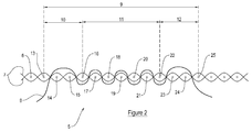
Figure 2 is a diagrammatic sectional view of a preferred embodiment of the invention in which a tether is attached to an air-bag; -
Figure 3 is a graph showing the results of burst test experiments carried out on an embodiment of the invention and a conventional baseline arrangement; -
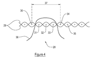
Figure 4 is a diagrammatic sectional view of a further embodiment of the invention with a tether attached to an air-bag; and -
Figure 5 is a diagrammatic view of an air-bag of a further embodiment of the invention. - Referring now to
figure 2 , at least part of an air-bag 5 is woven and comprises a plurality of woven warp andweft yarns 6, 7. The woven warp yarns 6 form a plurality of generally parallel yarns. Thewoven weft yarns 7 also form a plurality of generally parallel yarns. - In one embodiment, the air-bag is a one piece woven (OPW) air-bag. However, in other embodiments, the air-bag 5 is formed using a different weaving technique to one piece weaving.
- It is to be appreciated that
figure 2 only shows one layer of part of the air-bag 5 and that the air-bag 5 may incorporate other layers. - In this embodiment, a flexible
elongate tether 8 is attached to the air-bag 5 by anattachment arrangement 9. In a preferred embodiment, thetether 8 is formed from a plurality of woven tether yarns. Only one tether yarn is shown infigure 2 but, in this embodiment, thetether 8 comprises a plurality of tether yarns. - The
attachment arrangement 9 comprises yarns 6 of the air-bag 5 which retain part of thetether 8 to attach thetether 8 to the air-bag 5. In this embodiment, at least one tether yarn of thetether 8 is retained by theattachment arrangement 9 to attach thetether 8 to the air-bag 5. For simplicity purposes, the following description refers to thetether 8 but it is to be appreciated that part of thetether 8 is attached to the air-bag 5 and the part of thetether 8 is at least one tether yarn of thetether 8. - In this embodiment, the
attachment arrangement 9 comprises warp yarns 6 of the air-bag 5 but in other embodiments, theattachment arrangement 9 comprisesweft yarns 7 of the air-bag 5. Thetether 8 is preferably attached to the air-bag 5 during an OPW weaving process for forming the air-bag 5. - The
attachment arrangement 9 comprises afirst portion 10, asecond portion 11 and athird portion 12. Each portion 10-12 of theattachment arrangement 9 comprises a respective number of warp yarns 6 of the air-bag 5 and an arrangement in which thetether 8 passes between or over the warp yarns 6. - In the
first portion 10 of theattachment arrangement 9, thetether 8 passes between twoadjacent warp yarns adjacent warp yarns tether 8 passes partly around two or more adjacent warp yarns 6 on one side of the air-bags, the tether is said to "float" over adjacent warp yarns 6, as opposed to being interwoven between single warp adjacent yarns 6. The term "adjacent" is used here to mean two warp yarns that are positioned immediately next to one another. - In other embodiments, the
tether 8 passes partly around more than two adjacent warp yarns 6 in thefirst portion 10 of theattachment arrangement 9. In one embodiment, thetether 8 passes partly around three adjacent warp yarns 6 in thefirst portion 10 of theattachment arrangement 9. - In the
second portion 11 of theattachment arrangement 9, thetether 8 passes between twowarp yarns tether 8 is interwoven with a predetermined number of single adjacent warp yarns 17-21. In thesecond portion 11 of theattachment arrangement 9, thetether 8 interwoven with seven adjacent single warp yarns 16-22. Thetether 8 passes at least partly around threewarp yarns - In other embodiments, the
tether 8 interwoven with more than seven single adjacent warp yarns. In one embodiment, thetether 8 is interwoven with thirteen single adjacent warp yarns in thesecond portion 11 of theattachment 9. - In the
third portion 12 of theattachment arrangement 9, thetether 8 passes between twoadjacent warp yarns 22, 23 from one side of the air-bag 5 to another side of the air-bag 5 and then passes partly around twoadjacent warp yarns tether 8 then passes between a further twoadjacent warp yarns - In other embodiments, the
tether 8 passes partly around more than two adjacent warp yarns in thethird portion 12 of theattachment arrangement 9. In one embodiment, thetether 8 passes partly around three adjacent warp yarns in thethird portion 12 of theattachment arrangement 9. - In the embodiments described above, the
tether 8 passes partly around at least two adjacent warp yarns in the first andthird portions attachment arrangement 9. Thetether 8 is interwoven with single adjacent warp yarns 16-21 in thesecond portion 11 of theattachment arrangement 9. Passing thetether 8 partly around at least two adjacent warp yarns on one side of the air-bag 5 in the first andthird portions attachment arrangement 9 allows some movement between thetether 8 and air-bag 5 which absorbs some of the shock load when the air-bag 5 is inflated. This minimises the chance of thetether 8 breaking as the air-bag 5 is inflated. - To improve the performance of the air-bag 5, the length of the first and
third portions attachment arrangement 9 is, in one embodiment, minimised with respect to the length of thesecond portion 11 of theattachment arrangement 9. This helps to minimise gas leakage from the air-bag at the point where the tether is attached to the air-bag. -
Figure 3 shows the result of an experiment to test the burst strength of the air-bag 5 upon inflation. The maximum pressure reached within the air-bag 5 before the air-bag bursts or ruptures is shown by the peaks of the lines of the graph. - A
first line 26 shows the baseline pressure readings during inflation of an air-bag in which a tether is attached to the air-bag in a conventional manner. In this comparative example, the tether is attached to the air-bag by being interwoven with thirteen single adjacent warp yarns. - The
second line 27 of the graph shown infigure 3 represents the measured pressure within the air-bag 5 of an embodiment of the invention. In this embodiment, thetether 8 is attached to the air-bag 5 by anattachment arrangement 9 in which thetether 8 passes partly around three adjacent warp yarns in thefirst portion 10, thetether 8 is interwoven with thirteen single adjacent warp yarns in thesecond portion 11 and thetether 8 passes partly around three adjacent warp yarns in thethird portion 12. - It is clear from the graph shown in
figure 3 that when the tether is attached to the air-bag in accordance with an embodiment of the invention, the air-bag can withstand a higher pressure before bursting than the baseline conventional arrangement. - Referring now to
figure 4 , a further embodiment of the invention comprises a section of an air-bag 28 formed fromweft yarns 29 and warp yarns 30-35. Atether 36 is attached to the air-bag 28 by anattachment arrangement 37. Theattachment arrangement 37 comprises at least three warp yarns 31-33 of the air-bag 28. - Part of the
tether 36, formed by at least one tether yarn, passes between twowarp yarns bag 28 to a second side of the air-bag 28 and then passes partly around at least three warp yarns 31-33 on the second side of the air-bag 28. In further embodiments, thetether 36 passes partly around more than three warp yarns on the second side of the air-bag 28. Thetether 36 then passes between twowarp yarns bag 28 from the second side of the air-bag 28 to the first side of the air-bag 28. - In this embodiment, the
tether 36 is not interwoven with single adjacent yarns of the air-bag 28. - This embodiment allows the
tether 36 to move relative to the yarns of the air-bag 28 upon inflation. Energy is absorbed as thetether 36 moves relative to the air-bag 28. The energy absorption minimises the possibility of thetether 36 breaking when the air-bag 28 is inflated. - Referring now to
figure 5 , one embodiment of the invention comprises a safety device in the form of an air-bag 38 which is an inflatable curtain air-bag or a pedestrian-protecting air-bag. The air-bag 38 is woven from warp yarns substantially aligned with the direction indicated byarrow 39 and weft yarns substantially aligned with the direction indicated byarrow 40. The air-bag 38 incorporates seams 41-44 at its edges.Tether yarns 45 are connected to the air-bag 38 by aconnection arrangement 46 which comprises at least afirst portion 47 and asecond portion 48. In this embodiment, the connection arrangement comprises athird portion 49. In other embodiments, thethird portion 49 of theconnection arrangement 46 is omitted. - The
tether yarns 45 are connected to an upper layer of the air-bag 38 at thefirst portion 47 of theconnection arrangement 46 by part of each of thetether yarns 45 passing between two yarns of the air-bag 38 from a first side of the air-bag 38 to a second side of the air-bag 38 and then partly around at least three yarns on the second side of the air-bag 38, in the configuration as shown infigure 4 and as described above. - The
tether yarns 45 are connected to the air-bag 38 at thesecond portion 48 of theconnection arrangement 46 by being inter-woven between at least seven single adjacent yarns of the air-bag 38 in the same manner as thesecond portion 11 of theattachment arrangement 9 shown infigure 2 and as described above. - In this embodiment, the first and
second portions connection arrangement 46 are adjacent one another and thefirst portion 47 of theconnection arrangement 46 is positioned adjacent aseam 41 of the air-bag 38 such that thefirst portion 47 is positioned between theseam 41 and thesecond portion 48 of theconnection arrangement 46. This embodiment has the benefit of thefirst portion 47 of theconnection arrangement 46 which is adjacent theseam 41 absorbing energy to minimise the possibility of thetether yarns 45 breaking. Thesecond portion 48 of theconnection arrangement 46 provides the further benefit of a strong connection between thetether yarns 45 and the air-bag 38. - In this embodiment, the
third portion 49 of theconnection arrangement 46 is the same connection type as thefirst portion 47. Thethird portion 49 allows energy to be absorbed from thetether yarns 45 adjacent theseam 43 of the air-bag 38 in a similar manner to thefirst portion 47 of theconnection arrangement 46 as described above. - In this embodiment, the
tether yarns 45 are also connected to the air-bag 38 by second andthird connection arrangements first connection arrangement 46 as described above. However, in other embodiments, thetether yarns 45 are connected to the air-bag 38 by only one connection arrangement or by more than three connection arrangements. - Embodiments of the invention are described above with a tether passing between or partly around warp yarns of an air-bag. However, in other embodiments, the tether passes between and at least partly around weft yarns of an air-bag.
- Embodiments of the invention may be incorporated in any type of safety device which comprises an airbag and a tether. In one embodiment, a tether is attached within an inflatable curtain (IC) type air-bag. In another embodiment, a tether is attached to a pedestrian-protecting air-bag. In a further embodiment, the tether is attached to an air-bag which is packed inside a vehicle air-bag module.
- In the present specification "comprise" means "includes or consists of" and "comprising" means "including or consisting of".
Claims (15)
- A safety device for use in a vehicle, the safety device comprising:an air-bag (5) configured to be inflated by a source of gas, at least part of the air-bag (5) being woven and comprising a plurality of generally parallel woven yarns (6); andan elongate tether (8), the tether (8) being connected to the air-bag (5) by a connection arrangement (9) which comprises:a first portion (10) in which part of the tether (8) passes between two adjacent yarns (13, 14) of the air-bag (5) from one side of the air-bag (5) to another side of the air-bag (5) and partly around at least two adjacent yarns (14, 15) of the air-bag (5) on one side of the air-bag (5);a second portion (11) in which part of the tether (8) is interwoven with a predetermined number of single adjacent yarns (16-21) of the air-bag (5); anda third portion (12) in which part of the tether (8) passes between two adjacent yarns (22, 23) of the air-bag (5) from one side of the air-bag (5) to another side of the air-bag (5) and partly around at least two adjacent yarns (23, 24) of the air-bag (5) on one side of the air-bag (5).
- The safety device of claim 1, wherein in the first portion (10) of the attachment arrangement (9), the tether (8) passes partly around at least three adjacent yarns of the air-bag (5) on one side of the air-bag (5).
- The safety device of claim 1 or claim 2, wherein in the second portion (11) of the attachment arrangement (9), the tether (8) is interwoven with at least seven adjacent single yarns of the air-bag (5).
- The safety device of claim 1 or claim 2, wherein in the second portion (11) of the attachment arrangement (9), the tether (8) is interwoven with at least thirteen adjacent single yarns of the air-bag (5).
- The safety device of any one of the preceding claims, wherein in the third portion (12) of the attachment arrangement (9), the tether (8) passes partly around at least three adjacent yarns of the air-bag (5) on one side of the air-bag (5).
- A safety device for use in a vehicle, the safety device comprising:an air-bag (28, 38) configured to be inflated by a source of gas, at least part of the air-bag (28, 38) being woven and comprising a plurality of generally parallel woven yarns (29); andan elongate tether (36, 45) connected to the air-bag (28, 38) by a connection arrangement (37, 46) which comprises:a first portion in which part of the tether (36,45) passes between two adjacent yarns (30, 31) of the air-bag (28, 38) from a first side of the air-bag (28, 38) to a second side of the air-bag (28, 38) and partly around at least three adjacent yarns (31-33) of the air-bag (28, 38) on the second side of the air-bag (28, 38), and between a further two adjacent yarns (33, 34) of the air-bag (28, 38) from the second side of the air-bag (28, 38) to the first side of the air-bag (28, 38).
- The safety device of claim 6, wherein the connection arrangement (46) comprises a second portion (48) in which part of the tether (45) is inter-woven with a plurality of single adjacent yarns of the air-bag (38).
- The safety device of claim 7, wherein the first and second portions (47, 48) of the connection arrangement (46) are adjacent one another and the first portion (47) of the connection arrangement (46) is adjacent a seam (41) of the air-bag (38) such that the first portion (47) of the connection arrangement (46) is positioned between the seam (41) and the second portion (48) of the connection arrangement (46).
- A method of manufacturing a safety device for use in a vehicle, the method comprising:weaving part of an air-bag (5) to comprise a plurality of generally parallel woven yarns (6);providing an elongate tether (8); andconnecting the tether (8) to the air-bag (5) by:passing a first part of the tether (8) between two adjacent yarns (13, 14) of the air-bag (5) from one side of the air-bag (5) to another side of the air-bag (5) and partly around at least two adjacent yarns (14-15) of the air-bag (5) on one side of the air-bag (5);interweaving a second part of the tether (8) with a predetermined number of single adjacent yarns (16-21) of the air-bag (5); andpassing a third part of the tether (8) between two adjacent yarns (22, 23) of the air-bag (5) from one side of the air-bag (5) to another side of the air-bag (5) and partly around at least two adjacent yarns (23, 24) of the air-bag (5) on one side of the air-bag (5).
- The method of claim 9, wherein the method comprises:passing the first part of the tether (8) partly around at least three adjacent yarns of the air-bag (5) on one side of the air-bag (5).
- The method of claim 9 or claim 10, wherein the method comprises:interweaving the second part of the tether (8) with at least seven single adjacent yarns of the air-bag (5).
- The method of any one of claims 9 to 11, wherein the method comprises:interweaving the second part of the tether (8) with at least thirteen single adjacent yarns of the air-bag (5); andpassing the third part of the tether (8) partly around at least three adjacent yarns of the air-bag (5) on one side of the air-bag (5).
- A method of manufacturing a safety device for use in a vehicle, the method comprising:weaving part of an air-bag, (28, 38) to comprise a plurality of generally parallel woven yarns (29);providing an elongate tether (36, 45); andattaching the tether (36, 45) to the air-bag (28, 38) at a first portion (47) of a connection arrangement (37, 46) by:passing part of the tether (36, 45) between two adjacent yarns (30, 31) of the air-bag (28, 38) from a first side of the air-bag (28, 38) to a second side of the air-bag (28, 38) and partly around at least three adjacent yarns (31-33) of the air-bag (28, 38) on the second side of the air-bag (28, 38); andpassing part of the tether (36, 45) between a further two adjacent yarns (33, 34) of the air-bag (28, 38) from the second side of the air-bag (28, 38) to the first side of the air-bag (28, 38).
- The method of claim 13, wherein the method further comprises:attaching the tether (45) to the air-bag (38) at a second portion (48) of the connection arrangement (46) by:inter-weaving a part of the tether (45) with a plurality of single adjacent yarns of the air-bag (38).
- The method of claim 14, wherein the first and second portions (47, 48) of the connection arrangement (46) are adjacent one another and the first portion (47) of the connection arrangement (46) is adjacent a seam (41) of the air-bag (38) such that the first portion (47) of the connection arrangement (46) is positioned between the seam (41) and the second portion (48) of the connection arrangement (46).
Priority Applications (4)
| Application Number | Priority Date | Filing Date | Title |
|---|---|---|---|
| EP13188640.0A EP2862754B1 (en) | 2013-10-15 | 2013-10-15 | A safety device |
| US15/029,488 US10017147B2 (en) | 2013-10-15 | 2014-10-13 | Safety device |
| JP2016520134A JP6289623B2 (en) | 2013-10-15 | 2014-10-13 | Safety device |
| PCT/SE2014/051207 WO2015057140A1 (en) | 2013-10-15 | 2014-10-13 | A safety device |
Applications Claiming Priority (1)
| Application Number | Priority Date | Filing Date | Title |
|---|---|---|---|
| EP13188640.0A EP2862754B1 (en) | 2013-10-15 | 2013-10-15 | A safety device |
Publications (2)
| Publication Number | Publication Date |
|---|---|
| EP2862754A1 true EP2862754A1 (en) | 2015-04-22 |
| EP2862754B1 EP2862754B1 (en) | 2017-08-02 |
Family
ID=49356293
Family Applications (1)
| Application Number | Title | Priority Date | Filing Date |
|---|---|---|---|
| EP13188640.0A Active EP2862754B1 (en) | 2013-10-15 | 2013-10-15 | A safety device |
Country Status (4)
| Country | Link |
|---|---|
| US (1) | US10017147B2 (en) |
| EP (1) | EP2862754B1 (en) |
| JP (1) | JP6289623B2 (en) |
| WO (1) | WO2015057140A1 (en) |
Families Citing this family (4)
| Publication number | Priority date | Publication date | Assignee | Title |
|---|---|---|---|---|
| EP3020607B1 (en) * | 2013-07-09 | 2018-08-29 | Sumisho Airbag Systems Co., Ltd. | Air-bag |
| JP6716926B2 (en) * | 2016-01-27 | 2020-07-01 | トヨタ紡織株式会社 | Curtain shield airbag |
| JP6376704B2 (en) * | 2016-02-19 | 2018-08-22 | 住商エアバッグ・システムズ株式会社 | Bag |
| DE102018124099B3 (en) * | 2018-09-28 | 2019-08-22 | Global Safety Textiles Gmbh | In a piece woven airbag |
Citations (2)
| Publication number | Priority date | Publication date | Assignee | Title |
|---|---|---|---|---|
| EP2221405A1 (en) * | 2009-02-18 | 2010-08-25 | Autoliv Development AB | An airbag |
| DE102011017207A1 (en) * | 2011-04-15 | 2012-10-18 | Global Safety Textiles Gmbh | OPW airbag |
Family Cites Families (5)
| Publication number | Priority date | Publication date | Assignee | Title |
|---|---|---|---|---|
| US6742805B2 (en) * | 2001-05-02 | 2004-06-01 | Trw Vehicle Safety Systems Inc. | Multi-layered inflatable curtain |
| JP2006096086A (en) * | 2004-09-28 | 2006-04-13 | Toyoda Gosei Co Ltd | Airbag |
| US20070200329A1 (en) * | 2006-02-27 | 2007-08-30 | Key Safety Systems, Inc. | Woven air bag with integrally woven 3-D tethers |
| EP2407353B1 (en) | 2010-07-16 | 2013-03-27 | Autoliv Development AB | A motor vehicle safety device |
| DE102012008114A1 (en) * | 2012-04-25 | 2013-10-31 | Trw Automotive Gmbh | Airbag for a vehicle occupant restraint system |
-
2013
- 2013-10-15 EP EP13188640.0A patent/EP2862754B1/en active Active
-
2014
- 2014-10-13 JP JP2016520134A patent/JP6289623B2/en active Active
- 2014-10-13 US US15/029,488 patent/US10017147B2/en active Active
- 2014-10-13 WO PCT/SE2014/051207 patent/WO2015057140A1/en not_active Ceased
Patent Citations (2)
| Publication number | Priority date | Publication date | Assignee | Title |
|---|---|---|---|---|
| EP2221405A1 (en) * | 2009-02-18 | 2010-08-25 | Autoliv Development AB | An airbag |
| DE102011017207A1 (en) * | 2011-04-15 | 2012-10-18 | Global Safety Textiles Gmbh | OPW airbag |
Also Published As
| Publication number | Publication date |
|---|---|
| EP2862754B1 (en) | 2017-08-02 |
| JP2016534920A (en) | 2016-11-10 |
| US10017147B2 (en) | 2018-07-10 |
| US20160264090A1 (en) | 2016-09-15 |
| JP6289623B2 (en) | 2018-03-07 |
| WO2015057140A1 (en) | 2015-04-23 |
Similar Documents
| Publication | Publication Date | Title |
|---|---|---|
| EP3362324B1 (en) | Airbags including internal tethers and methods of forming the same | |
| EP2407353B1 (en) | A motor vehicle safety device | |
| CN110962789B (en) | Integrally woven airbag | |
| EP2862754B1 (en) | A safety device | |
| KR20210122158A (en) | OPW airbag | |
| US9283922B2 (en) | Airbag for a vehicle occupant restraint system | |
| US20150367807A1 (en) | One-piece woven airbag | |
| EP2769885B1 (en) | An air-bag | |
| JP4248541B2 (en) | Inflatable vehicle occupant protection device | |
| CN107667039B (en) | Airbag for an airbag module | |
| EP3042806B1 (en) | Airbag and manufacturing method therefor | |
| WO2017146852A1 (en) | Airbag fabric including apertures and methods of forming the same | |
| US10315611B2 (en) | One-piece woven vehicle occupant protection device | |
| EP2994352A1 (en) | Airbag for a motor vehicle | |
| CN114514345A (en) | Multi-layer fabric | |
| JP2019182117A (en) | Airbag | |
| JP6211210B2 (en) | Improvement of airbag or improvement related to airbag | |
| JP2017087864A (en) | Head protection airbag | |
| JP2015202856A (en) | Hollow weave air bag | |
| JP2020059306A (en) | Air bag | |
| JP2020019450A (en) | Air bag and manufacturing method therefor |
Legal Events
| Date | Code | Title | Description |
|---|---|---|---|
| PUAI | Public reference made under article 153(3) epc to a published international application that has entered the european phase |
Free format text: ORIGINAL CODE: 0009012 |
|
| 17P | Request for examination filed |
Effective date: 20131015 |
|
| AK | Designated contracting states |
Kind code of ref document: A1 Designated state(s): AL AT BE BG CH CY CZ DE DK EE ES FI FR GB GR HR HU IE IS IT LI LT LU LV MC MK MT NL NO PL PT RO RS SE SI SK SM TR |
|
| AX | Request for extension of the european patent |
Extension state: BA ME |
|
| R17P | Request for examination filed (corrected) |
Effective date: 20151020 |
|
| RBV | Designated contracting states (corrected) |
Designated state(s): AL AT BE BG CH CY CZ DE DK EE ES FI FR GB GR HR HU IE IS IT LI LT LU LV MC MK MT NL NO PL PT RO RS SE SI SK SM TR |
|
| GRAP | Despatch of communication of intention to grant a patent |
Free format text: ORIGINAL CODE: EPIDOSNIGR1 |
|
| INTG | Intention to grant announced |
Effective date: 20170224 |
|
| GRAS | Grant fee paid |
Free format text: ORIGINAL CODE: EPIDOSNIGR3 |
|
| GRAA | (expected) grant |
Free format text: ORIGINAL CODE: 0009210 |
|
| AK | Designated contracting states |
Kind code of ref document: B1 Designated state(s): AL AT BE BG CH CY CZ DE DK EE ES FI FR GB GR HR HU IE IS IT LI LT LU LV MC MK MT NL NO PL PT RO RS SE SI SK SM TR |
|
| REG | Reference to a national code |
Ref country code: CH Ref legal event code: EP Ref country code: AT Ref legal event code: REF Ref document number: 914073 Country of ref document: AT Kind code of ref document: T Effective date: 20170815 |
|
| REG | Reference to a national code |
Ref country code: IE Ref legal event code: FG4D |
|
| REG | Reference to a national code |
Ref country code: DE Ref legal event code: R096 Ref document number: 602013024292 Country of ref document: DE |
|
| REG | Reference to a national code |
Ref country code: FR Ref legal event code: PLFP Year of fee payment: 5 |
|
| REG | Reference to a national code |
Ref country code: NL Ref legal event code: MP Effective date: 20170802 |
|
| REG | Reference to a national code |
Ref country code: AT Ref legal event code: MK05 Ref document number: 914073 Country of ref document: AT Kind code of ref document: T Effective date: 20170802 |
|
| REG | Reference to a national code |
Ref country code: LT Ref legal event code: MG4D |
|
| PG25 | Lapsed in a contracting state [announced via postgrant information from national office to epo] |
Ref country code: NL Free format text: LAPSE BECAUSE OF FAILURE TO SUBMIT A TRANSLATION OF THE DESCRIPTION OR TO PAY THE FEE WITHIN THE PRESCRIBED TIME-LIMIT Effective date: 20170802 Ref country code: LT Free format text: LAPSE BECAUSE OF FAILURE TO SUBMIT A TRANSLATION OF THE DESCRIPTION OR TO PAY THE FEE WITHIN THE PRESCRIBED TIME-LIMIT Effective date: 20170802 Ref country code: FI Free format text: LAPSE BECAUSE OF FAILURE TO SUBMIT A TRANSLATION OF THE DESCRIPTION OR TO PAY THE FEE WITHIN THE PRESCRIBED TIME-LIMIT Effective date: 20170802 Ref country code: AT Free format text: LAPSE BECAUSE OF FAILURE TO SUBMIT A TRANSLATION OF THE DESCRIPTION OR TO PAY THE FEE WITHIN THE PRESCRIBED TIME-LIMIT Effective date: 20170802 Ref country code: SE Free format text: LAPSE BECAUSE OF FAILURE TO SUBMIT A TRANSLATION OF THE DESCRIPTION OR TO PAY THE FEE WITHIN THE PRESCRIBED TIME-LIMIT Effective date: 20170802 Ref country code: NO Free format text: LAPSE BECAUSE OF FAILURE TO SUBMIT A TRANSLATION OF THE DESCRIPTION OR TO PAY THE FEE WITHIN THE PRESCRIBED TIME-LIMIT Effective date: 20171102 Ref country code: HR Free format text: LAPSE BECAUSE OF FAILURE TO SUBMIT A TRANSLATION OF THE DESCRIPTION OR TO PAY THE FEE WITHIN THE PRESCRIBED TIME-LIMIT Effective date: 20170802 |
|
| PG25 | Lapsed in a contracting state [announced via postgrant information from national office to epo] |
Ref country code: BG Free format text: LAPSE BECAUSE OF FAILURE TO SUBMIT A TRANSLATION OF THE DESCRIPTION OR TO PAY THE FEE WITHIN THE PRESCRIBED TIME-LIMIT Effective date: 20171102 Ref country code: LV Free format text: LAPSE BECAUSE OF FAILURE TO SUBMIT A TRANSLATION OF THE DESCRIPTION OR TO PAY THE FEE WITHIN THE PRESCRIBED TIME-LIMIT Effective date: 20170802 Ref country code: IS Free format text: LAPSE BECAUSE OF FAILURE TO SUBMIT A TRANSLATION OF THE DESCRIPTION OR TO PAY THE FEE WITHIN THE PRESCRIBED TIME-LIMIT Effective date: 20171202 Ref country code: ES Free format text: LAPSE BECAUSE OF FAILURE TO SUBMIT A TRANSLATION OF THE DESCRIPTION OR TO PAY THE FEE WITHIN THE PRESCRIBED TIME-LIMIT Effective date: 20170802 Ref country code: RS Free format text: LAPSE BECAUSE OF FAILURE TO SUBMIT A TRANSLATION OF THE DESCRIPTION OR TO PAY THE FEE WITHIN THE PRESCRIBED TIME-LIMIT Effective date: 20170802 Ref country code: GR Free format text: LAPSE BECAUSE OF FAILURE TO SUBMIT A TRANSLATION OF THE DESCRIPTION OR TO PAY THE FEE WITHIN THE PRESCRIBED TIME-LIMIT Effective date: 20171103 Ref country code: PL Free format text: LAPSE BECAUSE OF FAILURE TO SUBMIT A TRANSLATION OF THE DESCRIPTION OR TO PAY THE FEE WITHIN THE PRESCRIBED TIME-LIMIT Effective date: 20170802 |
|
| PG25 | Lapsed in a contracting state [announced via postgrant information from national office to epo] |
Ref country code: CZ Free format text: LAPSE BECAUSE OF FAILURE TO SUBMIT A TRANSLATION OF THE DESCRIPTION OR TO PAY THE FEE WITHIN THE PRESCRIBED TIME-LIMIT Effective date: 20170802 Ref country code: DK Free format text: LAPSE BECAUSE OF FAILURE TO SUBMIT A TRANSLATION OF THE DESCRIPTION OR TO PAY THE FEE WITHIN THE PRESCRIBED TIME-LIMIT Effective date: 20170802 Ref country code: RO Free format text: LAPSE BECAUSE OF FAILURE TO SUBMIT A TRANSLATION OF THE DESCRIPTION OR TO PAY THE FEE WITHIN THE PRESCRIBED TIME-LIMIT Effective date: 20170802 |
|
| REG | Reference to a national code |
Ref country code: DE Ref legal event code: R097 Ref document number: 602013024292 Country of ref document: DE |
|
| PG25 | Lapsed in a contracting state [announced via postgrant information from national office to epo] |
Ref country code: EE Free format text: LAPSE BECAUSE OF FAILURE TO SUBMIT A TRANSLATION OF THE DESCRIPTION OR TO PAY THE FEE WITHIN THE PRESCRIBED TIME-LIMIT Effective date: 20170802 Ref country code: SK Free format text: LAPSE BECAUSE OF FAILURE TO SUBMIT A TRANSLATION OF THE DESCRIPTION OR TO PAY THE FEE WITHIN THE PRESCRIBED TIME-LIMIT Effective date: 20170802 Ref country code: IT Free format text: LAPSE BECAUSE OF FAILURE TO SUBMIT A TRANSLATION OF THE DESCRIPTION OR TO PAY THE FEE WITHIN THE PRESCRIBED TIME-LIMIT Effective date: 20170802 Ref country code: MC Free format text: LAPSE BECAUSE OF FAILURE TO SUBMIT A TRANSLATION OF THE DESCRIPTION OR TO PAY THE FEE WITHIN THE PRESCRIBED TIME-LIMIT Effective date: 20170802 Ref country code: SM Free format text: LAPSE BECAUSE OF FAILURE TO SUBMIT A TRANSLATION OF THE DESCRIPTION OR TO PAY THE FEE WITHIN THE PRESCRIBED TIME-LIMIT Effective date: 20170802 |
|
| REG | Reference to a national code |
Ref country code: CH Ref legal event code: PL |
|
| PLBE | No opposition filed within time limit |
Free format text: ORIGINAL CODE: 0009261 |
|
| STAA | Information on the status of an ep patent application or granted ep patent |
Free format text: STATUS: NO OPPOSITION FILED WITHIN TIME LIMIT |
|
| 26N | No opposition filed |
Effective date: 20180503 |
|
| REG | Reference to a national code |
Ref country code: IE Ref legal event code: MM4A |
|
| PG25 | Lapsed in a contracting state [announced via postgrant information from national office to epo] |
Ref country code: CH Free format text: LAPSE BECAUSE OF NON-PAYMENT OF DUE FEES Effective date: 20171031 Ref country code: LI Free format text: LAPSE BECAUSE OF NON-PAYMENT OF DUE FEES Effective date: 20171031 Ref country code: LU Free format text: LAPSE BECAUSE OF NON-PAYMENT OF DUE FEES Effective date: 20171015 |
|
| REG | Reference to a national code |
Ref country code: BE Ref legal event code: MM Effective date: 20171031 |
|
| PG25 | Lapsed in a contracting state [announced via postgrant information from national office to epo] |
Ref country code: BE Free format text: LAPSE BECAUSE OF NON-PAYMENT OF DUE FEES Effective date: 20171031 Ref country code: SI Free format text: LAPSE BECAUSE OF FAILURE TO SUBMIT A TRANSLATION OF THE DESCRIPTION OR TO PAY THE FEE WITHIN THE PRESCRIBED TIME-LIMIT Effective date: 20170802 |
|
| PG25 | Lapsed in a contracting state [announced via postgrant information from national office to epo] |
Ref country code: MT Free format text: LAPSE BECAUSE OF NON-PAYMENT OF DUE FEES Effective date: 20171015 |
|
| PG25 | Lapsed in a contracting state [announced via postgrant information from national office to epo] |
Ref country code: IE Free format text: LAPSE BECAUSE OF NON-PAYMENT OF DUE FEES Effective date: 20171015 |
|
| REG | Reference to a national code |
Ref country code: FR Ref legal event code: PLFP Year of fee payment: 6 |
|
| PG25 | Lapsed in a contracting state [announced via postgrant information from national office to epo] |
Ref country code: HU Free format text: LAPSE BECAUSE OF FAILURE TO SUBMIT A TRANSLATION OF THE DESCRIPTION OR TO PAY THE FEE WITHIN THE PRESCRIBED TIME-LIMIT; INVALID AB INITIO Effective date: 20131015 |
|
| PG25 | Lapsed in a contracting state [announced via postgrant information from national office to epo] |
Ref country code: CY Free format text: LAPSE BECAUSE OF FAILURE TO SUBMIT A TRANSLATION OF THE DESCRIPTION OR TO PAY THE FEE WITHIN THE PRESCRIBED TIME-LIMIT Effective date: 20170802 |
|
| PG25 | Lapsed in a contracting state [announced via postgrant information from national office to epo] |
Ref country code: MK Free format text: LAPSE BECAUSE OF FAILURE TO SUBMIT A TRANSLATION OF THE DESCRIPTION OR TO PAY THE FEE WITHIN THE PRESCRIBED TIME-LIMIT Effective date: 20170802 |
|
| PG25 | Lapsed in a contracting state [announced via postgrant information from national office to epo] |
Ref country code: TR Free format text: LAPSE BECAUSE OF FAILURE TO SUBMIT A TRANSLATION OF THE DESCRIPTION OR TO PAY THE FEE WITHIN THE PRESCRIBED TIME-LIMIT Effective date: 20170802 |
|
| PG25 | Lapsed in a contracting state [announced via postgrant information from national office to epo] |
Ref country code: PT Free format text: LAPSE BECAUSE OF FAILURE TO SUBMIT A TRANSLATION OF THE DESCRIPTION OR TO PAY THE FEE WITHIN THE PRESCRIBED TIME-LIMIT Effective date: 20170802 |
|
| PG25 | Lapsed in a contracting state [announced via postgrant information from national office to epo] |
Ref country code: AL Free format text: LAPSE BECAUSE OF FAILURE TO SUBMIT A TRANSLATION OF THE DESCRIPTION OR TO PAY THE FEE WITHIN THE PRESCRIBED TIME-LIMIT Effective date: 20170802 |
|
| P01 | Opt-out of the competence of the unified patent court (upc) registered |
Effective date: 20230507 |
|
| PGFP | Annual fee paid to national office [announced via postgrant information from national office to epo] |
Ref country code: DE Payment date: 20251028 Year of fee payment: 13 |
|
| PGFP | Annual fee paid to national office [announced via postgrant information from national office to epo] |
Ref country code: GB Payment date: 20251023 Year of fee payment: 13 |
|
| PGFP | Annual fee paid to national office [announced via postgrant information from national office to epo] |
Ref country code: FR Payment date: 20251027 Year of fee payment: 13 |