EP2862632B1 - Refill system - Google Patents
Refill system Download PDFInfo
- Publication number
- EP2862632B1 EP2862632B1 EP13189039.4A EP13189039A EP2862632B1 EP 2862632 B1 EP2862632 B1 EP 2862632B1 EP 13189039 A EP13189039 A EP 13189039A EP 2862632 B1 EP2862632 B1 EP 2862632B1
- Authority
- EP
- European Patent Office
- Prior art keywords
- container
- refill
- wall
- sealing structure
- opening
- Prior art date
- Legal status (The legal status is an assumption and is not a legal conclusion. Google has not performed a legal analysis and makes no representation as to the accuracy of the status listed.)
- Active
Links
- 238000007789 sealing Methods 0.000 claims description 86
- 239000007788 liquid Substances 0.000 claims description 48
- 238000009423 ventilation Methods 0.000 claims description 14
- 239000002304 perfume Substances 0.000 claims description 9
- 238000006073 displacement reaction Methods 0.000 description 4
- 238000003780 insertion Methods 0.000 description 2
- 230000037431 insertion Effects 0.000 description 2
- 238000012423 maintenance Methods 0.000 description 2
- 230000001419 dependent effect Effects 0.000 description 1
- 239000003205 fragrance Substances 0.000 description 1
- 230000036651 mood Effects 0.000 description 1
- 239000007921 spray Substances 0.000 description 1
Images


Classifications
-
- B—PERFORMING OPERATIONS; TRANSPORTING
- B05—SPRAYING OR ATOMISING IN GENERAL; APPLYING FLUENT MATERIALS TO SURFACES, IN GENERAL
- B05B—SPRAYING APPARATUS; ATOMISING APPARATUS; NOZZLES
- B05B11/00—Single-unit hand-held apparatus in which flow of contents is produced by the muscular force of the operator at the moment of use
- B05B11/0005—Components or details
- B05B11/0037—Containers
- B05B11/0056—Containers with an additional opening for filling or refilling
-
- B—PERFORMING OPERATIONS; TRANSPORTING
- B05—SPRAYING OR ATOMISING IN GENERAL; APPLYING FLUENT MATERIALS TO SURFACES, IN GENERAL
- B05B—SPRAYING APPARATUS; ATOMISING APPARATUS; NOZZLES
- B05B11/00—Single-unit hand-held apparatus in which flow of contents is produced by the muscular force of the operator at the moment of use
- B05B11/0005—Components or details
- B05B11/0037—Containers
- B05B11/0038—Inner container disposed in an outer shell or outer casing
-
- B—PERFORMING OPERATIONS; TRANSPORTING
- B05—SPRAYING OR ATOMISING IN GENERAL; APPLYING FLUENT MATERIALS TO SURFACES, IN GENERAL
- B05B—SPRAYING APPARATUS; ATOMISING APPARATUS; NOZZLES
- B05B11/00—Single-unit hand-held apparatus in which flow of contents is produced by the muscular force of the operator at the moment of use
- B05B11/01—Single-unit hand-held apparatus in which flow of contents is produced by the muscular force of the operator at the moment of use characterised by the means producing the flow
- B05B11/10—Pump arrangements for transferring the contents from the container to a pump chamber by a sucking effect and forcing the contents out through the dispensing nozzle
- B05B11/1042—Components or details
- B05B11/1043—Sealing or attachment arrangements between pump and container
- B05B11/1046—Sealing or attachment arrangements between pump and container the pump chamber being arranged substantially coaxially to the neck of the container
- B05B11/1047—Sealing or attachment arrangements between pump and container the pump chamber being arranged substantially coaxially to the neck of the container the pump being preassembled as an independent unit before being mounted on the container
-
- B—PERFORMING OPERATIONS; TRANSPORTING
- B05—SPRAYING OR ATOMISING IN GENERAL; APPLYING FLUENT MATERIALS TO SURFACES, IN GENERAL
- B05B—SPRAYING APPARATUS; ATOMISING APPARATUS; NOZZLES
- B05B11/00—Single-unit hand-held apparatus in which flow of contents is produced by the muscular force of the operator at the moment of use
- B05B11/01—Single-unit hand-held apparatus in which flow of contents is produced by the muscular force of the operator at the moment of use characterised by the means producing the flow
- B05B11/10—Pump arrangements for transferring the contents from the container to a pump chamber by a sucking effect and forcing the contents out through the dispensing nozzle
- B05B11/1042—Components or details
- B05B11/1052—Actuation means
- B05B11/1053—Actuation means combined with means, other than pressure, for automatically opening a valve during actuation; combined with means for automatically removing closures or covers from the discharge nozzle during actuation
-
- B—PERFORMING OPERATIONS; TRANSPORTING
- B05—SPRAYING OR ATOMISING IN GENERAL; APPLYING FLUENT MATERIALS TO SURFACES, IN GENERAL
- B05B—SPRAYING APPARATUS; ATOMISING APPARATUS; NOZZLES
- B05B11/00—Single-unit hand-held apparatus in which flow of contents is produced by the muscular force of the operator at the moment of use
- B05B11/01—Single-unit hand-held apparatus in which flow of contents is produced by the muscular force of the operator at the moment of use characterised by the means producing the flow
- B05B11/10—Pump arrangements for transferring the contents from the container to a pump chamber by a sucking effect and forcing the contents out through the dispensing nozzle
- B05B11/1042—Components or details
- B05B11/1052—Actuation means
- B05B11/1056—Actuation means comprising rotatable or articulated levers
- B05B11/1057—Triggers, i.e. actuation means consisting of a single lever having one end rotating or pivoting around an axis or a hinge fixedly attached to the container, and another end directly actuated by the user
Definitions
- the invention relates to a refill system, in particular for liquids.
- a refill system according to the preamble of claim 1 is known from WO 97/26210 A2 , US 2012/158193 A1 , CN 103213767 A and CN 103204315 A .
- the problem solved by the present invention is to further develop a refill system, in particular for refilling liquids, which is improved with regard to its sealing ability in a confined space.
- This problem is solved by a refill system comprising the features of claim 1.
- Preferable embodiments are set forth in the dependent claims.
- the refill system comprises a container structure, having a wall with a refill opening, and a sealing structure, wherein the sealing structure is held by the container structure movably along the wall with the refill opening and is movable between a first position, which closes the refill opening, and a second position, which opens the refill opening.
- the advantage of this arrangement is that the sealing structure moves in a direction perpendicular to the flow path of a liquid through the refill opening. Thereby, it is less likely that the sealing structure will be accidently brought into its second position by means of liquid pressure from within the container structure.
- the sealing structure comprises a container seal with at least one clearance hole for refill, preferably two clearance holes, more preferably three clearance, wherein the container seal is biased against the wall with the refill opening from the container structure by means of at least one elastic element such that the container seal is in liquid-tight contact with the wall.
- the clearance hole allows a minimal displacement of the container seal in order to open the refill opening. Also, the biasing force acting on the container seal ensures the necessary liquid tightness.
- the sealing structure is held inside the container structure so that it does not protrude from the outer circumference of the container structure. This ensures that the sealing structure is less likely to be accidently displaced into its second position, because it remains hidden.
- a refill system wherein the sealing structure is held slidably movable between the inner wall with the refill opening and an outer wall of the container structure.
- the outer wall is capable of keeping the sealing structure close to the wall with the refill opening or at least preventing the sealing structure from distancing itself from said wall and said refill opening, which would result in a increased likelihood for leakage.
- the outer wall is part of a container enclosure, which is fixedly attached to the outside of a liquid container, wherein both the container enclosure and the liquid container form part of the container structure. This allows compensating for tolerances in production and providing an adjustable tight fit of the sealing structure between the inner and outer wall. It also simplifies the assembly.
- the container enclosure is fixedly attached to the outside of the liquid container at the side with the wall with the refill opening. This way the extra space needed at that side of the liquid container for the sealing structure is also used for attaching the enclosure and the container, wherein the sides of the container structure can be kept thin.
- the container enclosure is cone-shaped and basically corresponds to the shape of the liquid container at its side with the wall with the refill opening, such that the container enclosure can be put onto the liquid container with its base portion forming the outer wall.
- a refill system wherein the sealing structure is held in its first position by form fit of an locking element with the container structure so that a movement of the sealing structure along the wall with the refill opening is prevented. This allows a secure positioning of the locking element compared to a purely friction based positioning.
- the form fit of the locking element with the container structure is held by a locking elastic element which biases the locking element in a direction towards the container structure.
- the locking element is constantly urged to return to its locked position and reliably held there in order to prevent unintentional or accidental displacement of the sealing structure.
- a pushing force on the locking element against the biasing locking elastic element releases the form fit and thus allows a movement of the sealing structure along the wall with the refill opening into its second position. This results in a two-step safety, because first a pushing force is required to unlock the sealing structure and second a sliding movement along the wall with the refill opening is required to reach the second position of the sealing structure.
- the sealing structure is biased from the inside of the container structure in a direction along the wall with the refill opening by means of a releasing elastic element.
- the elastic element reduces the manual operation need for moving the sealing structure out of its first position while also maintaining the second position while a refill operation is carried out in order to avoid an unintentional displacement of the sealing structure toward its first position during the refill.
- the sealing structure is held together in a direction along the wall with the refill opening by means of a sealing frame structure.
- said frame structure allows the insertion or removal of further sealing structure components in a direction different from the direction along the wall with the refill opening; More preferably, in a direction perpendicular to the wall with the refill opening.
- any other sealing structure components such as a container seal or refill seal, can be inserted separately and securely in a direction which is different from the movement direction of the sealing structure, which further simplifies the assembly.
- the sealing frame structure can be moved either manually or automatically by means of the releasing elastic element in a direction along the wall with the refill opening.
- the sealing structure comprises a conduit element which is liquid-tightly connected to the refill opening and leads to a refill seal which serves for abutment of a stem of a donor liquid container.
- the conduit element can serve as a contact area for the releasing elastic element and/or as an inner support for the biasing elastic element. It could also be an extension serving to arrange the abutment for a stem of a donor liquid container in a desired location.
- the sealing structure closes in its first position and opens in its second position a ventilation opening.
- a ventilation opening ensures a faster refill, because, while liquid is filled through the refill opening, air can be discharged through the ventilation opening. Closing and opening both openings with one sealing structure simplifies the operation of the refill system.
- the ventilation opening is provided on the wall with the refill opening. Having both openings close by allows the sealing structure to have smaller dimensions.
- a perfume bottle has the above described refill system.
- the particular use in a perfume bottle (flacon) is desirable, because perfumes are often changed depending on the user's mood or specific occasions.
- small liquid containers can often be refilled with different fragrances.
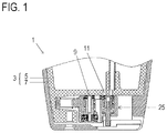
- Figures 1 and 2 show the assembled state of a refill system of a perfume bottle according to the invention.
- Figure 3 shows an exploded view of the bottom of the perfume bottle with the refill system and all of its elements.
- the refill system 1 shown in Fig. 3 comprises a perfume bottle, i.e. a container structure 3, which is formed by an inner liquid container 5 and an outer container enclosure 7.
- the bottom of the liquid container 5 has a wall with 9 a refill opening 11 and a ventilation opening 13 as well as a collar portion 15 further extending perpendicularly outwards from the wall 9 and having a bore 17 with an inner thread in the direction of the extension.
- the container enclosure 7 is cone-shaped and basically corresponds to the shape of the liquid container 5 at its bottom side, i.e. its side with the wall 9 with the refill opening 11, such that the container enclosure 7 can be put onto the liquid container 5 from the bottom with its base portion forming an outer wall 19 abutting against the collar portion 15 of the liquid container 5.
- Said outer wall 19 is parallel to the wall 9 with the refill opening 11 and has a chamfered clearance hole 21 on the side of the collar portion 15 of the liquid container 5 and a partial cut-out 23 on the opposite side.
- the container enclosure 7 is fixedly attached to the outside of the liquid container 5 at the side with the wall 9 with the refill opening 11 by means of a screw which reaches through the chamfered clearance hole 19 and is screwed into the bore 17 of the collar portion 15 of the liquid container 5.
- a sealing structure 25 is held slidably movable between the inner wall 9 with the refill opening 11 and the outer wall 19 of the container structure 3 along the wall 9 with the refill opening 11.
- the sealing structure 25 is movable between a first position, which closes the refill opening 11 and is shown in Fig. 1 , and a second position, which opens the refill opening 11 and is shown in Fig. 2 .
- the sealing structure 25 does not protrude from the outer circumference of the container structure 3. As shown in Fig.
- the sealing structure 25 has a container seal 27, a conduit element 29, a sealing elastic element 31 (in form of a coil spring), a locking tube element 33, a locking elastic element 35 (in form of a coil spring), a locking pin 37 and a sealing frame structure 39, which are inserted from one side of the sealing frame structure 39, which is the side towards the wall 9 with the refill opening 11 of the liquid container 5.
- the sealing structure 25 further has an elastic refill seal 41, which is inserted from the other side of the sealing frame structure 39 and biased by snap connection with the conduit element 29 liquid tightly against a portion of the frame structure 39.
- the sealing structure 25 is held together in a direction along the wall 9 with the refill opening 11 by means of the sealing frame structure 39, which allows the insertion or removal of further sealing structure components in a direction different from the direction along the wall 9 with the refill opening 11, in particular in a direction perpendicular to the wall 9 with the refill opening 11.
- the above described sealing structure 25 is biased by a releasing elastic element 43 (in form of a coil spring) in a direction along the wall 9 with the refill opening 11.
- the releasing elastic element 43 being interposed between a side wall of the frame structure 39 and an inner undercut of the liquid container 5, which undercut is between the collar portion 15 and the wall 9 with the refill opening 11, urges the sealing structure 25 in a direction towards its second position.
- the sealing structure 25 abuts the inside of a side wall of the container enclosure 7.
- a locking element 45 (in form of a flat button plate) is placed on the end of the locking pin 37 that is opposite to the end towards the wall 9 with the refill opening 11.
- This locking element 45 has a two-step width, such that it engages in a form fit with the partial cut-out 23 of the container enclosure 7, thus practically closing the cut-out 23 and being flush with the outer bottom face of the container enclosure 7.
- the sealing structure 25 is held in its first position by form fit of the locking element 45 with the container structure 3, in particular the container enclosure 7, so that a movement of the sealing structure 25 along the wall 9 with the refill opening 11 and towards the its second position is prevented.
- That form fit of the locking element 45 with the container structure 3 is held by the locking elastic element 35 which biases the locking element 45 in a direction towards/against the container structure 3.
- the container seal 27 is biased against the wall 9 with the refill opening 11 by means of the sealing elastic element 31 and the locking elastic element 35 such that the container seal 27 is in liquid-tight contact with the wall 9.
- the container seal has three clearance holes 27a-c (from left to right in Fig.
- the container seal 27 is biased against the wall 9 with the refill opening 11 from the container structure 3. Both, the refill opening 11 and the ventilation opening 13 are closed by the container seal 27, when the sealing structure 25 is in its first position.
- the sealing structure 25 is in its second position. This position is reached when a pushing force is exercised on the locking element 45 against the biasing locking elastic element 35, so that the form fit is released and a movement of the sealing structure 25 along the wall 9 with the refill opening 11 into its second position becomes possible. Because the sealing structure 25 is biased from the inside of the container structure 3 in a direction along the wall 9 with the refill opening 11 by means of the releasing elastic element 43 towards the second position, the sealing structure 25 is automatically moved into its second position and stopped by abutment against the inside of the side wall of the container enclosure 7. In this second position the clearance hole for refill 27a and the clearance hole for ventilation 27b align with the respective refill opening 11 and ventilation opening 13 in the liquid container 5.
- the elastic refill seal 41 becomes exposed to the outside such that a stem of a liquid donor tank can be brought into proper placement.
- the locking element 45 is pushed sideways outside the container enclosure 3, so that it can be manually pushed back towards the inside in order to return the sealing structure 25 into its first position.
- liquid can flow through a stem of a liquid donor tank, pass a central clearance hole in the refill seal 41, continue through the conduit element 29, pass the clearance hole for refill 27a in the container seal 27 and the refill opening 11 before entering the liquid container 5, which is shown by the two coaxial arrows pointing upwards.
- the conduit element 29 is liquid-tightly connected to the refill opening 11 and leads to a refill seal 41 which serves for abutment of a stem of a donor liquid container.
Description
- The invention relates to a refill system, in particular for liquids.
- A refill system according to the preamble of
claim 1 is known fromWO 97/26210 A2 US 2012/158193 A1 ,CN 103213767 A andCN 103204315 A . - The problem solved by the present invention is to further develop a refill system, in particular for refilling liquids, which is improved with regard to its sealing ability in a confined space.
This problem is solved by a refill system comprising the features ofclaim 1. Preferable embodiments are set forth in the dependent claims. - The refill system according to the invention comprises a container structure, having a wall with a refill opening, and a sealing structure, wherein the sealing structure is held by the container structure movably along the wall with the refill opening and is movable between a first position, which closes the refill opening, and a second position, which opens the refill opening.
The advantage of this arrangement is that the sealing structure moves in a direction perpendicular to the flow path of a liquid through the refill opening. Thereby, it is less likely that the sealing structure will be accidently brought into its second position by means of liquid pressure from within the container structure. - Further, the sealing structure comprises a container seal with at least one clearance hole for refill, preferably two clearance holes, more preferably three clearance, wherein the container seal is biased against the wall with the refill opening from the container structure by means of at least one elastic element such that the container seal is in liquid-tight contact with the wall.
The clearance hole allows a minimal displacement of the container seal in order to open the refill opening. Also, the biasing force acting on the container seal ensures the necessary liquid tightness. - It is in particular advantageous that the sealing structure is held inside the container structure so that it does not protrude from the outer circumference of the container structure.
This ensures that the sealing structure is less likely to be accidently displaced into its second position, because it remains hidden. - Further advantageous is a refill system, wherein the sealing structure is held slidably movable between the inner wall with the refill opening and an outer wall of the container structure.
The outer wall is capable of keeping the sealing structure close to the wall with the refill opening or at least preventing the sealing structure from distancing itself from said wall and said refill opening, which would result in a increased likelihood for leakage. - In that regard, it is advantageous that the outer wall is part of a container enclosure, which is fixedly attached to the outside of a liquid container, wherein both the container enclosure and the liquid container form part of the container structure.
This allows compensating for tolerances in production and providing an adjustable tight fit of the sealing structure between the inner and outer wall. It also simplifies the assembly. - Particularly advantageous is that the container enclosure is fixedly attached to the outside of the liquid container at the side with the wall with the refill opening. This way the extra space needed at that side of the liquid container for the sealing structure is also used for attaching the enclosure and the container, wherein the sides of the container structure can be kept thin.
- Further advantageous is a refill system, wherein the container enclosure is cone-shaped and basically corresponds to the shape of the liquid container at its side with the wall with the refill opening, such that the container enclosure can be put onto the liquid container with its base portion forming the outer wall.
An increased stability of the liquid container is the result of the above, because the enclosure can cover a large part of the container. At the same time the sealing structure is aesthetically hidden in what appears to be a slightly bigger liquid container. - Further advantageous is a refill system, wherein the sealing structure is held in its first position by form fit of an locking element with the container structure so that a movement of the sealing structure along the wall with the refill opening is prevented.
This allows a secure positioning of the locking element compared to a purely friction based positioning. - It is in particular advantageous that the form fit of the locking element with the container structure is held by a locking elastic element which biases the locking element in a direction towards the container structure.
Hence, the locking element is constantly urged to return to its locked position and reliably held there in order to prevent unintentional or accidental displacement of the sealing structure. - It is further particularly advantageous that a pushing force on the locking element against the biasing locking elastic element releases the form fit and thus allows a movement of the sealing structure along the wall with the refill opening into its second position.
This results in a two-step safety, because first a pushing force is required to unlock the sealing structure and second a sliding movement along the wall with the refill opening is required to reach the second position of the sealing structure. - Advantageously, the sealing structure is biased from the inside of the container structure in a direction along the wall with the refill opening by means of a releasing elastic element.
The elastic element reduces the manual operation need for moving the sealing structure out of its first position while also maintaining the second position while a refill operation is carried out in order to avoid an unintentional displacement of the sealing structure toward its first position during the refill. - Further advantageously, the sealing structure is held together in a direction along the wall with the refill opening by means of a sealing frame structure. Preferably, said frame structure allows the insertion or removal of further sealing structure components in a direction different from the direction along the wall with the refill opening; More preferably, in a direction perpendicular to the wall with the refill opening.
Hence, any other sealing structure components, such as a container seal or refill seal, can be inserted separately and securely in a direction which is different from the movement direction of the sealing structure, which further simplifies the assembly. Further, regardless of the number of sealing structure components, they can be held together by the sealing frame structure, which can be moved either manually or automatically by means of the releasing elastic element in a direction along the wall with the refill opening. - It is in particular advantageous that the sealing structure comprises a conduit element which is liquid-tightly connected to the refill opening and leads to a refill seal which serves for abutment of a stem of a donor liquid container.
The conduit element can serve as a contact area for the releasing elastic element and/or as an inner support for the biasing elastic element. It could also be an extension serving to arrange the abutment for a stem of a donor liquid container in a desired location. - Further advantageously, the sealing structure closes in its first position and opens in its second position a ventilation opening.
The provision of a ventilation opening ensures a faster refill, because, while liquid is filled through the refill opening, air can be discharged through the ventilation opening. Closing and opening both openings with one sealing structure simplifies the operation of the refill system. - It is in particular advantageous that the ventilation opening is provided on the wall with the refill opening.
Having both openings close by allows the sealing structure to have smaller dimensions. - Advantageously, a perfume bottle has the above described refill system. The particular use in a perfume bottle (flacon) is desirable, because perfumes are often changed depending on the user's mood or specific occasions. By providing such an efficient refill system, small liquid containers can often be refilled with different fragrances.
-
- Fig. 1
- shows the embodiment according to the invention, where the sealing structure is in a first position which closes a refill opening.
- Fig. 2
- shows the embodiment according to the invention, where the sealing structure is in a second position which opens the refill opening.
- Fig. 3
- shows an exploded view of the refill system according to the invention shown in
Figures 1 and2 . - Fig. 4
- shows a variation of the embodiment according to the invention shown in
Figures 1 to 3 . - Fig. 5
- shows a perfume bottle (flacon) with the refill system according to the invention at its bottom (towards the right edge of the sheet) and a mechanism for triggering the spray of said perfume bottle at its top (towards the left edge of the sheet), wherein the mechanism is not according to the invention.
-
Figures 1 and2 show the assembled state of a refill system of a perfume bottle according to the invention.Figure 3 shows an exploded view of the bottom of the perfume bottle with the refill system and all of its elements. - The
refill system 1 shown inFig. 3 comprises a perfume bottle, i.e. acontainer structure 3, which is formed by an innerliquid container 5 and anouter container enclosure 7.
The bottom of theliquid container 5 has a wall with 9 a refill opening 11 and a ventilation opening 13 as well as acollar portion 15 further extending perpendicularly outwards from thewall 9 and having abore 17 with an inner thread in the direction of the extension.
Thecontainer enclosure 7 is cone-shaped and basically corresponds to the shape of theliquid container 5 at its bottom side, i.e. its side with thewall 9 with therefill opening 11, such that thecontainer enclosure 7 can be put onto theliquid container 5 from the bottom with its base portion forming anouter wall 19 abutting against thecollar portion 15 of theliquid container 5. Saidouter wall 19 is parallel to thewall 9 with therefill opening 11 and has a chamferedclearance hole 21 on the side of thecollar portion 15 of theliquid container 5 and a partial cut-out 23 on the opposite side. - The
container enclosure 7 is fixedly attached to the outside of theliquid container 5 at the side with thewall 9 with therefill opening 11 by means of a screw which reaches through the chamferedclearance hole 19 and is screwed into thebore 17 of thecollar portion 15 of theliquid container 5. - Inside the container structure 3 a sealing
structure 25 is held slidably movable between theinner wall 9 with therefill opening 11 and theouter wall 19 of thecontainer structure 3 along thewall 9 with therefill opening 11. Thereby, the sealingstructure 25 is movable between a first position, which closes therefill opening 11 and is shown inFig. 1 , and a second position, which opens therefill opening 11 and is shown inFig. 2 . The sealingstructure 25 does not protrude from the outer circumference of thecontainer structure 3.
As shown inFig. 3 , the sealingstructure 25 has acontainer seal 27, aconduit element 29, a sealing elastic element 31 (in form of a coil spring), a lockingtube element 33, a locking elastic element 35 (in form of a coil spring), a lockingpin 37 and a sealingframe structure 39, which are inserted from one side of the sealingframe structure 39, which is the side towards thewall 9 with the refill opening 11 of theliquid container 5. The sealingstructure 25 further has anelastic refill seal 41, which is inserted from the other side of the sealingframe structure 39 and biased by snap connection with theconduit element 29 liquid tightly against a portion of theframe structure 39. Hence, the sealingstructure 25 is held together in a direction along thewall 9 with therefill opening 11 by means of the sealingframe structure 39, which allows the insertion or removal of further sealing structure components in a direction different from the direction along thewall 9 with therefill opening 11, in particular in a direction perpendicular to thewall 9 with therefill opening 11. - The above described sealing
structure 25 is biased by a releasing elastic element 43 (in form of a coil spring) in a direction along thewall 9 with therefill opening 11. In other words, the releasingelastic element 43 being interposed between a side wall of theframe structure 39 and an inner undercut of theliquid container 5, which undercut is between thecollar portion 15 and thewall 9 with therefill opening 11, urges the sealingstructure 25 in a direction towards its second position. In this position, the sealingstructure 25 abuts the inside of a side wall of thecontainer enclosure 7. Further, a locking element 45 (in form of a flat button plate) is placed on the end of the lockingpin 37 that is opposite to the end towards thewall 9 with therefill opening 11. This lockingelement 45 has a two-step width, such that it engages in a form fit with the partial cut-out 23 of thecontainer enclosure 7, thus practically closing the cut-out 23 and being flush with the outer bottom face of thecontainer enclosure 7. - The function of the
refill system 1 will be described in the following, based onFigures 1 and2 . - In
Fig. 1 the sealingstructure 25 is held in its first position by form fit of the lockingelement 45 with thecontainer structure 3, in particular thecontainer enclosure 7, so that a movement of the sealingstructure 25 along thewall 9 with therefill opening 11 and towards the its second position is prevented. That form fit of the lockingelement 45 with thecontainer structure 3 is held by the lockingelastic element 35 which biases the lockingelement 45 in a direction towards/against thecontainer structure 3. Thecontainer seal 27 is biased against thewall 9 with therefill opening 11 by means of the sealingelastic element 31 and the lockingelastic element 35 such that thecontainer seal 27 is in liquid-tight contact with thewall 9. The container seal has threeclearance holes 27a-c (from left to right inFig. 3 , for example); one 27a for refilling, one 27b for ventilation and one 27c for accommodating one end of the lockingtube element 33. Regardless of its position, thecontainer seal 27 is biased against thewall 9 with the refill opening 11 from thecontainer structure 3. Both, therefill opening 11 and theventilation opening 13 are closed by thecontainer seal 27, when the sealingstructure 25 is in its first position. - In
Fig. 2 the sealingstructure 25 is in its second position. This position is reached when a pushing force is exercised on the lockingelement 45 against the biasing lockingelastic element 35, so that the form fit is released and a movement of the sealingstructure 25 along thewall 9 with the refill opening 11 into its second position becomes possible. Because the sealingstructure 25 is biased from the inside of thecontainer structure 3 in a direction along thewall 9 with therefill opening 11 by means of the releasingelastic element 43 towards the second position, the sealingstructure 25 is automatically moved into its second position and stopped by abutment against the inside of the side wall of thecontainer enclosure 7. In this second position the clearance hole forrefill 27a and the clearance hole forventilation 27b align with the respective refill opening 11 andventilation opening 13 in theliquid container 5. Also, theelastic refill seal 41 becomes exposed to the outside such that a stem of a liquid donor tank can be brought into proper placement. At the same time, the lockingelement 45 is pushed sideways outside thecontainer enclosure 3, so that it can be manually pushed back towards the inside in order to return the sealingstructure 25 into its first position.
In the second position of the sealingstructure 25, liquid can flow through a stem of a liquid donor tank, pass a central clearance hole in therefill seal 41, continue through theconduit element 29, pass the clearance hole forrefill 27a in thecontainer seal 27 and therefill opening 11 before entering theliquid container 5, which is shown by the two coaxial arrows pointing upwards. Hence, theconduit element 29 is liquid-tightly connected to therefill opening 11 and leads to arefill seal 41 which serves for abutment of a stem of a donor liquid container. - While liquid is being refilled into the
liquid container 5, gas can escape to the outside through theventilation opening 13, a clearance forventilation 27b in thecontainer seal 27 and a ventilation path, which is created between an intermediate wall of theframe structure 39 on one side andcomponents - The following points describe further advantageous features of the invention, which can individually be combined with the above embodiment:
- The sealing
structure 25 is sandwiched betweenwalls container structure 3, preferably between theliquid container 5 and thecontainer enclosure 7. This ensures a tight hold of the sealingstructure 25, such that it seals and remains movable at the same time. - The
liquid container 5 and thecontainer enclosure 7 are preferably connected by means of a snap connection, preferably a detachable snap connection. Such a configuration does not require additional elements, such as screws. Also, the sealingstructure 25 can be reached for maintenance/replacement easily and tool-free. - The sealing
structure 25 is nondestructively removable and replaceable from thecontainer structure 3. This offers greater safety during maintenance and better failure/damage analysis. - The sealing
structure 25 comprises at least anelastic container seal 27 that is movable along thewall 9 with therefill opening 11, wherein one face of the container seal is biased by thecontainer structure 3 against thewall 9 with therefill opening 11 and the opposite face is at least partially exposed to the outside and providing a surface structure that is suitable for moving theelastic container seal 25 manually along the wall with the refill opening.
This further simplifies the configuration of the sealingstructure 25 to only one element, namely theelastic container seal 27. - The
liquid container 5 has abottom wall portion 47, as shown inFig. 4 , that is capable of holding the sealingstructure 25 to theliquid container 5 and guiding the sealingstructure 25 between its first and second position. Preferably, thebottom wall portion 47 extends perpendicular to thewall 9 with therefill opening 11 and is capable of enclosing the sealingstructure 25 there between. More preferably, thebottom wall portion 47 is capable of guiding the sealingstructure 25 by means of apath 49, whichpath 49 is preferably cut out through saidbottom wall portion 47 to provide a track for ansidewise extension 51 of the sealingstructure 25, preferably a pin shaped element.
Thereby, when theliquid container 5 and thecontainer enclosure 7 are disassembled from each other, the sealing structure is held with theliquid container 5, such that none of its components will separate and fall off, which makes an exchange of container enclosure, for example with one having a different color, easier. - The sealing
structure 25 comprises at least anelastic container seal 27 and a lesselastic frame structure 39 that supports, preferably by basically surrounding it, and moves thecontainer seal 27 along thewall 9 with the refill opening 11 upon manual displacement of theframe structure 39.
This way friction can be reduced, due to the reduced elasticity of theframe structure 39 and the resulting reduced friction of theframe structure 39 with thecontainer structure 3 compared to a sealingstructure 25 that only consists of anelastic container seal 27.
Claims (14)
- Refill system (1) comprising a container structure (3), having a wall (9) with a refill opening (11), and a sealing structure (25), wherein
the sealing structure (25) is held by the container structure (3) movably along the wall (9) with the refill opening (11) and is movable between a first position, which closes the refill opening (11), and a second position, which opens the refill opening (11),
the sealing structure (25) comprising a container seal (27) with at least
one clearance hole (27a), preferably two clearance holes (27a, 27b), more preferably three clearance holes (27a, 27b, 27c),
characterized in that the container seal (27) is biased against the wall (9) with the refill opening (11) from the container structure (3) by means of at least one elastic element (31, 35) such that the container seal (27) is in liquid-tight contact with the wall (9). - Refill system (1) according to claim 1, wherein
the sealing structure (25) is held inside the container structure (3) so that it does not protrude from the outer circumference of the container structure (3). - Refill system (1) according to claim 1 or 2, wherein
the sealing structure (25) is held slidably movable between the inner wall (9) with the refill opening (11) and an outer wall (19) of the container structure (3). - Refill system (1) according to claim 3, wherein
the outer wall (19) is part of a container enclosure (7), which is fixedly attached to the outside of a liquid container (5), wherein both, the container enclosure (7) and the liquid container (5), form part of the container structure (3). - Refill system (1) according to claim 4, wherein
the container enclosure (7) is fixedly attached to the outside of the liquid container (5) at the side with the wall (9) with the refill opening (11). - Refill system (1) according to claim 4 or 5, wherein
the container enclosure (7) is cone-shaped and basically corresponds to the shape of the liquid container (5) at its side with the wall (9) with the refill opening (11), such that the container enclosure (7) can be put onto the liquid container (5) with its base portion forming the outer wall (19). - Refill system (1) according to claims 1 to 6, wherein
the sealing structure (25) is held in its first position by form fit of an locking element (45) with the container structure (3) so that a movement of the sealing structure (25) along the wall (9) with the refill opening (11) is prevented. - Refill system (1) according to claim 7, wherein
the form fit of the locking element (45) with the container structure (3) is held by a locking elastic element (35) which biases the locking element (45) in a direction towards the container structure (3). - Refill system (1) according to claim 8, wherein
a pushing force on the locking element (45) against the biasing locking elastic element (35) releases the form fit and thus allows a movement of the sealing structure (25) along the wall (9) with the refill opening (11) into its second position. - Refill system (1) according to claims 1 to 9, wherein
the sealing structure (25) is biased from the inside of the container structure (3) in a direction along the wall (9) with the refill opening (11) by means of a releasing elastic element (43). - Refill system (1) according to claim 10, wherein
the sealing structure (25) comprises a conduit element (29) which is liquid-tightly connected to the refill opening (11) and leads to a refill seal (41) which serves for abutment of a stem of a donor liquid container. - Refill system (1) according to claims 1 to 11, wherein
the sealing structure (25) closes in its first position and opens in its second position a ventilation opening (13). - Refill system (1) according to claim 12, wherein
the ventilation opening (13) is provided on the wall (9) with the refill opening (11). - Perfume bottle with a refill system (1) according to one of the preceding claims.
Priority Applications (1)
| Application Number | Priority Date | Filing Date | Title |
|---|---|---|---|
| EP13189039.4A EP2862632B1 (en) | 2013-10-17 | 2013-10-17 | Refill system |
Applications Claiming Priority (1)
| Application Number | Priority Date | Filing Date | Title |
|---|---|---|---|
| EP13189039.4A EP2862632B1 (en) | 2013-10-17 | 2013-10-17 | Refill system |
Publications (2)
| Publication Number | Publication Date |
|---|---|
| EP2862632A1 EP2862632A1 (en) | 2015-04-22 |
| EP2862632B1 true EP2862632B1 (en) | 2016-06-08 |
Family
ID=49515170
Family Applications (1)
| Application Number | Title | Priority Date | Filing Date |
|---|---|---|---|
| EP13189039.4A Active EP2862632B1 (en) | 2013-10-17 | 2013-10-17 | Refill system |
Country Status (1)
| Country | Link |
|---|---|
| EP (1) | EP2862632B1 (en) |
Cited By (1)
| Publication number | Priority date | Publication date | Assignee | Title |
|---|---|---|---|---|
| US10875703B2 (en) * | 2017-06-16 | 2020-12-29 | Changzhou Ivorie Shengmei Packaging Technology Co., Ltd. | Compact liquid spraying bottle filled liquid from the bottom |
Families Citing this family (1)
| Publication number | Priority date | Publication date | Assignee | Title |
|---|---|---|---|---|
| FR3067953B1 (en) * | 2017-06-22 | 2020-06-19 | Albea Le Treport | DEVICE FOR DISPENSING A PRODUCT FROM A CONTAINER |
Family Cites Families (6)
| Publication number | Priority date | Publication date | Assignee | Title |
|---|---|---|---|---|
| FR1566121A (en) * | 1967-06-14 | 1969-05-02 | ||
| US5862948A (en) * | 1996-01-19 | 1999-01-26 | Sc Johnson Commerical Markets, Inc. | Docking station and bottle system |
| FR2949764B1 (en) * | 2009-09-07 | 2011-11-25 | Maitrise & Innovation | DISTRIBUTION DEVICE WITH MOBILE DIFFUSER AND FIXED SOCKET HAVING A MINIATURE ELECTRIC PUMP |
| CN202321216U (en) * | 2011-12-14 | 2012-07-11 | 东莞怡信磁碟有限公司 | Refillable spraying bottle |
| CN103204315A (en) * | 2013-04-26 | 2013-07-17 | 常州圣美包装制品有限公司 | Liquid spray bottle |
| CN103213767B (en) * | 2013-05-09 | 2015-07-22 | 无锡市福锐特机电技术有限公司 | Detachable chargeable liquid sprayer bottle |
-
2013
- 2013-10-17 EP EP13189039.4A patent/EP2862632B1/en active Active
Cited By (1)
| Publication number | Priority date | Publication date | Assignee | Title |
|---|---|---|---|---|
| US10875703B2 (en) * | 2017-06-16 | 2020-12-29 | Changzhou Ivorie Shengmei Packaging Technology Co., Ltd. | Compact liquid spraying bottle filled liquid from the bottom |
Also Published As
| Publication number | Publication date |
|---|---|
| EP2862632A1 (en) | 2015-04-22 |
Similar Documents
| Publication | Publication Date | Title |
|---|---|---|
| CA2652898C (en) | Fluid dispensing apparatus | |
| JP6415461B2 (en) | Refillable device for stuffing and dispensing fluid products | |
| MXPA04004858A (en) | Aerosol valve assembly. | |
| EP3409610A1 (en) | Water bottle with self-closing valve | |
| EP2862632B1 (en) | Refill system | |
| ATE393340T1 (en) | VALVE DEVICE | |
| US9475635B2 (en) | Aerosol sprayer with anti-drool valve | |
| RU2015120583A (en) | DRINK TANK AND VALVE FOR DRINK TANK | |
| KR100978850B1 (en) | Aerosol can having overpressure protector and valve assembly thereof | |
| US20150108147A1 (en) | Refill system | |
| US8317049B2 (en) | Vacuum breaker arrangement with externally protruding collapsible valve part | |
| EP4215476A1 (en) | Tap assembly | |
| WO2008062172A3 (en) | An aerosol device | |
| WO2014115838A1 (en) | Ejector | |
| JP6952991B2 (en) | Container with coating body | |
| JP6782663B2 (en) | Discharge container | |
| US9617064B2 (en) | Spray head for an aerosol tank | |
| CN220031525U (en) | Ink supply container | |
| CN217737408U (en) | Detachable water tank structure and air humidity adjusting device | |
| KR101901161B1 (en) | Aerosol can enabling to apply contents in a flower shape | |
| US9272299B2 (en) | Dispenser | |
| KR102415475B1 (en) | Safety valve with metal element for gas cartridge | |
| JP6710455B2 (en) | Discharge pump | |
| KR101751982B1 (en) | A cosmetic case of cream type | |
| US20140174445A1 (en) | Detachable inspiratory relief valve |
Legal Events
| Date | Code | Title | Description |
|---|---|---|---|
| PUAI | Public reference made under article 153(3) epc to a published international application that has entered the european phase |
Free format text: ORIGINAL CODE: 0009012 |
|
| 17P | Request for examination filed |
Effective date: 20131017 |
|
| AK | Designated contracting states |
Kind code of ref document: A1 Designated state(s): AL AT BE BG CH CY CZ DE DK EE ES FI FR GB GR HR HU IE IS IT LI LT LU LV MC MK MT NL NO PL PT RO RS SE SI SK SM TR |
|
| AX | Request for extension of the european patent |
Extension state: BA ME |
|
| R17P | Request for examination filed (corrected) |
Effective date: 20150826 |
|
| RBV | Designated contracting states (corrected) |
Designated state(s): AL AT BE BG CH CY CZ DE DK EE ES FI FR GB GR HR HU IE IS IT LI LT LU LV MC MK MT NL NO PL PT RO RS SE SI SK SM TR |
|
| GRAP | Despatch of communication of intention to grant a patent |
Free format text: ORIGINAL CODE: EPIDOSNIGR1 |
|
| RIC1 | Information provided on ipc code assigned before grant |
Ipc: B05B 11/00 20060101AFI20151120BHEP |
|
| INTG | Intention to grant announced |
Effective date: 20151218 |
|
| GRAS | Grant fee paid |
Free format text: ORIGINAL CODE: EPIDOSNIGR3 |
|
| GRAA | (expected) grant |
Free format text: ORIGINAL CODE: 0009210 |
|
| AK | Designated contracting states |
Kind code of ref document: B1 Designated state(s): AL AT BE BG CH CY CZ DE DK EE ES FI FR GB GR HR HU IE IS IT LI LT LU LV MC MK MT NL NO PL PT RO RS SE SI SK SM TR |
|
| REG | Reference to a national code |
Ref country code: GB Ref legal event code: FG4D |
|
| REG | Reference to a national code |
Ref country code: CH Ref legal event code: EP |
|
| REG | Reference to a national code |
Ref country code: IE Ref legal event code: FG4D |
|
| REG | Reference to a national code |
Ref country code: AT Ref legal event code: REF Ref document number: 804825 Country of ref document: AT Kind code of ref document: T Effective date: 20160715 |
|
| REG | Reference to a national code |
Ref country code: DE Ref legal event code: R096 Ref document number: 602013008345 Country of ref document: DE |
|
| REG | Reference to a national code |
Ref country code: LT Ref legal event code: MG4D |
|
| REG | Reference to a national code |
Ref country code: NL Ref legal event code: MP Effective date: 20160608 |
|
| REG | Reference to a national code |
Ref country code: FR Ref legal event code: PLFP Year of fee payment: 4 |
|
| PG25 | Lapsed in a contracting state [announced via postgrant information from national office to epo] |
Ref country code: NO Free format text: LAPSE BECAUSE OF FAILURE TO SUBMIT A TRANSLATION OF THE DESCRIPTION OR TO PAY THE FEE WITHIN THE PRESCRIBED TIME-LIMIT Effective date: 20160908 Ref country code: LT Free format text: LAPSE BECAUSE OF FAILURE TO SUBMIT A TRANSLATION OF THE DESCRIPTION OR TO PAY THE FEE WITHIN THE PRESCRIBED TIME-LIMIT Effective date: 20160608 Ref country code: FI Free format text: LAPSE BECAUSE OF FAILURE TO SUBMIT A TRANSLATION OF THE DESCRIPTION OR TO PAY THE FEE WITHIN THE PRESCRIBED TIME-LIMIT Effective date: 20160608 |
|
| REG | Reference to a national code |
Ref country code: AT Ref legal event code: MK05 Ref document number: 804825 Country of ref document: AT Kind code of ref document: T Effective date: 20160608 |
|
| PG25 | Lapsed in a contracting state [announced via postgrant information from national office to epo] |
Ref country code: RS Free format text: LAPSE BECAUSE OF FAILURE TO SUBMIT A TRANSLATION OF THE DESCRIPTION OR TO PAY THE FEE WITHIN THE PRESCRIBED TIME-LIMIT Effective date: 20160608 Ref country code: HR Free format text: LAPSE BECAUSE OF FAILURE TO SUBMIT A TRANSLATION OF THE DESCRIPTION OR TO PAY THE FEE WITHIN THE PRESCRIBED TIME-LIMIT Effective date: 20160608 Ref country code: NL Free format text: LAPSE BECAUSE OF FAILURE TO SUBMIT A TRANSLATION OF THE DESCRIPTION OR TO PAY THE FEE WITHIN THE PRESCRIBED TIME-LIMIT Effective date: 20160608 Ref country code: SE Free format text: LAPSE BECAUSE OF FAILURE TO SUBMIT A TRANSLATION OF THE DESCRIPTION OR TO PAY THE FEE WITHIN THE PRESCRIBED TIME-LIMIT Effective date: 20160608 Ref country code: GR Free format text: LAPSE BECAUSE OF FAILURE TO SUBMIT A TRANSLATION OF THE DESCRIPTION OR TO PAY THE FEE WITHIN THE PRESCRIBED TIME-LIMIT Effective date: 20160909 Ref country code: ES Free format text: LAPSE BECAUSE OF FAILURE TO SUBMIT A TRANSLATION OF THE DESCRIPTION OR TO PAY THE FEE WITHIN THE PRESCRIBED TIME-LIMIT Effective date: 20160608 Ref country code: LV Free format text: LAPSE BECAUSE OF FAILURE TO SUBMIT A TRANSLATION OF THE DESCRIPTION OR TO PAY THE FEE WITHIN THE PRESCRIBED TIME-LIMIT Effective date: 20160608 |
|
| PG25 | Lapsed in a contracting state [announced via postgrant information from national office to epo] |
Ref country code: RO Free format text: LAPSE BECAUSE OF FAILURE TO SUBMIT A TRANSLATION OF THE DESCRIPTION OR TO PAY THE FEE WITHIN THE PRESCRIBED TIME-LIMIT Effective date: 20160608 Ref country code: IS Free format text: LAPSE BECAUSE OF FAILURE TO SUBMIT A TRANSLATION OF THE DESCRIPTION OR TO PAY THE FEE WITHIN THE PRESCRIBED TIME-LIMIT Effective date: 20161008 Ref country code: CZ Free format text: LAPSE BECAUSE OF FAILURE TO SUBMIT A TRANSLATION OF THE DESCRIPTION OR TO PAY THE FEE WITHIN THE PRESCRIBED TIME-LIMIT Effective date: 20160608 Ref country code: EE Free format text: LAPSE BECAUSE OF FAILURE TO SUBMIT A TRANSLATION OF THE DESCRIPTION OR TO PAY THE FEE WITHIN THE PRESCRIBED TIME-LIMIT Effective date: 20160608 Ref country code: SK Free format text: LAPSE BECAUSE OF FAILURE TO SUBMIT A TRANSLATION OF THE DESCRIPTION OR TO PAY THE FEE WITHIN THE PRESCRIBED TIME-LIMIT Effective date: 20160608 |
|
| PG25 | Lapsed in a contracting state [announced via postgrant information from national office to epo] |
Ref country code: BE Free format text: LAPSE BECAUSE OF NON-PAYMENT OF DUE FEES Effective date: 20160608 Ref country code: PL Free format text: LAPSE BECAUSE OF FAILURE TO SUBMIT A TRANSLATION OF THE DESCRIPTION OR TO PAY THE FEE WITHIN THE PRESCRIBED TIME-LIMIT Effective date: 20160608 Ref country code: AT Free format text: LAPSE BECAUSE OF FAILURE TO SUBMIT A TRANSLATION OF THE DESCRIPTION OR TO PAY THE FEE WITHIN THE PRESCRIBED TIME-LIMIT Effective date: 20160608 Ref country code: PT Free format text: LAPSE BECAUSE OF FAILURE TO SUBMIT A TRANSLATION OF THE DESCRIPTION OR TO PAY THE FEE WITHIN THE PRESCRIBED TIME-LIMIT Effective date: 20161010 Ref country code: SM Free format text: LAPSE BECAUSE OF FAILURE TO SUBMIT A TRANSLATION OF THE DESCRIPTION OR TO PAY THE FEE WITHIN THE PRESCRIBED TIME-LIMIT Effective date: 20160608 |
|
| REG | Reference to a national code |
Ref country code: DE Ref legal event code: R097 Ref document number: 602013008345 Country of ref document: DE |
|
| PLBE | No opposition filed within time limit |
Free format text: ORIGINAL CODE: 0009261 |
|
| STAA | Information on the status of an ep patent application or granted ep patent |
Free format text: STATUS: NO OPPOSITION FILED WITHIN TIME LIMIT |
|
| 26N | No opposition filed |
Effective date: 20170309 |
|
| PG25 | Lapsed in a contracting state [announced via postgrant information from national office to epo] |
Ref country code: SI Free format text: LAPSE BECAUSE OF FAILURE TO SUBMIT A TRANSLATION OF THE DESCRIPTION OR TO PAY THE FEE WITHIN THE PRESCRIBED TIME-LIMIT Effective date: 20160608 Ref country code: DK Free format text: LAPSE BECAUSE OF FAILURE TO SUBMIT A TRANSLATION OF THE DESCRIPTION OR TO PAY THE FEE WITHIN THE PRESCRIBED TIME-LIMIT Effective date: 20160608 |
|
| REG | Reference to a national code |
Ref country code: CH Ref legal event code: PL |
|
| REG | Reference to a national code |
Ref country code: IE Ref legal event code: MM4A |
|
| PG25 | Lapsed in a contracting state [announced via postgrant information from national office to epo] |
Ref country code: CH Free format text: LAPSE BECAUSE OF NON-PAYMENT OF DUE FEES Effective date: 20161031 Ref country code: LI Free format text: LAPSE BECAUSE OF NON-PAYMENT OF DUE FEES Effective date: 20161031 |
|
| PG25 | Lapsed in a contracting state [announced via postgrant information from national office to epo] |
Ref country code: LU Free format text: LAPSE BECAUSE OF NON-PAYMENT OF DUE FEES Effective date: 20161017 |
|
| REG | Reference to a national code |
Ref country code: FR Ref legal event code: PLFP Year of fee payment: 5 |
|
| PG25 | Lapsed in a contracting state [announced via postgrant information from national office to epo] |
Ref country code: IE Free format text: LAPSE BECAUSE OF NON-PAYMENT OF DUE FEES Effective date: 20161017 |
|
| PG25 | Lapsed in a contracting state [announced via postgrant information from national office to epo] |
Ref country code: HU Free format text: LAPSE BECAUSE OF FAILURE TO SUBMIT A TRANSLATION OF THE DESCRIPTION OR TO PAY THE FEE WITHIN THE PRESCRIBED TIME-LIMIT; INVALID AB INITIO Effective date: 20131017 |
|
| PG25 | Lapsed in a contracting state [announced via postgrant information from national office to epo] |
Ref country code: CY Free format text: LAPSE BECAUSE OF FAILURE TO SUBMIT A TRANSLATION OF THE DESCRIPTION OR TO PAY THE FEE WITHIN THE PRESCRIBED TIME-LIMIT Effective date: 20160608 Ref country code: MK Free format text: LAPSE BECAUSE OF FAILURE TO SUBMIT A TRANSLATION OF THE DESCRIPTION OR TO PAY THE FEE WITHIN THE PRESCRIBED TIME-LIMIT Effective date: 20160608 Ref country code: MC Free format text: LAPSE BECAUSE OF FAILURE TO SUBMIT A TRANSLATION OF THE DESCRIPTION OR TO PAY THE FEE WITHIN THE PRESCRIBED TIME-LIMIT Effective date: 20160608 Ref country code: MT Free format text: LAPSE BECAUSE OF NON-PAYMENT OF DUE FEES Effective date: 20161031 |
|
| PG25 | Lapsed in a contracting state [announced via postgrant information from national office to epo] |
Ref country code: BG Free format text: LAPSE BECAUSE OF FAILURE TO SUBMIT A TRANSLATION OF THE DESCRIPTION OR TO PAY THE FEE WITHIN THE PRESCRIBED TIME-LIMIT Effective date: 20160608 |
|
| REG | Reference to a national code |
Ref country code: FR Ref legal event code: PLFP Year of fee payment: 6 |
|
| PG25 | Lapsed in a contracting state [announced via postgrant information from national office to epo] |
Ref country code: TR Free format text: LAPSE BECAUSE OF FAILURE TO SUBMIT A TRANSLATION OF THE DESCRIPTION OR TO PAY THE FEE WITHIN THE PRESCRIBED TIME-LIMIT Effective date: 20160608 Ref country code: AL Free format text: LAPSE BECAUSE OF FAILURE TO SUBMIT A TRANSLATION OF THE DESCRIPTION OR TO PAY THE FEE WITHIN THE PRESCRIBED TIME-LIMIT Effective date: 20160608 |
|
| PGFP | Annual fee paid to national office [announced via postgrant information from national office to epo] |
Ref country code: GB Payment date: 20231025 Year of fee payment: 11 |
|
| PGFP | Annual fee paid to national office [announced via postgrant information from national office to epo] |
Ref country code: IT Payment date: 20231031 Year of fee payment: 11 Ref country code: FR Payment date: 20231023 Year of fee payment: 11 Ref country code: DE Payment date: 20231025 Year of fee payment: 11 |