EP2862548B1 - Iris registration method and system - Google Patents
Iris registration method and system Download PDFInfo
- Publication number
- EP2862548B1 EP2862548B1 EP14182248.6A EP14182248A EP2862548B1 EP 2862548 B1 EP2862548 B1 EP 2862548B1 EP 14182248 A EP14182248 A EP 14182248A EP 2862548 B1 EP2862548 B1 EP 2862548B1
- Authority
- EP
- European Patent Office
- Prior art keywords
- eye
- iris
- images
- laser
- image
- Prior art date
- Legal status (The legal status is an assumption and is not a legal conclusion. Google has not performed a legal analysis and makes no representation as to the accuracy of the status listed.)
- Active
Links
Images


Classifications
-
- A—HUMAN NECESSITIES
- A61—MEDICAL OR VETERINARY SCIENCE; HYGIENE
- A61F—FILTERS IMPLANTABLE INTO BLOOD VESSELS; PROSTHESES; DEVICES PROVIDING PATENCY TO, OR PREVENTING COLLAPSING OF, TUBULAR STRUCTURES OF THE BODY, e.g. STENTS; ORTHOPAEDIC, NURSING OR CONTRACEPTIVE DEVICES; FOMENTATION; TREATMENT OR PROTECTION OF EYES OR EARS; BANDAGES, DRESSINGS OR ABSORBENT PADS; FIRST-AID KITS
- A61F9/00—Methods or devices for treatment of the eyes; Devices for putting in contact-lenses; Devices to correct squinting; Apparatus to guide the blind; Protective devices for the eyes, carried on the body or in the hand
- A61F9/007—Methods or devices for eye surgery
- A61F9/008—Methods or devices for eye surgery using laser
-
- A—HUMAN NECESSITIES
- A61—MEDICAL OR VETERINARY SCIENCE; HYGIENE
- A61F—FILTERS IMPLANTABLE INTO BLOOD VESSELS; PROSTHESES; DEVICES PROVIDING PATENCY TO, OR PREVENTING COLLAPSING OF, TUBULAR STRUCTURES OF THE BODY, e.g. STENTS; ORTHOPAEDIC, NURSING OR CONTRACEPTIVE DEVICES; FOMENTATION; TREATMENT OR PROTECTION OF EYES OR EARS; BANDAGES, DRESSINGS OR ABSORBENT PADS; FIRST-AID KITS
- A61F9/00—Methods or devices for treatment of the eyes; Devices for putting in contact-lenses; Devices to correct squinting; Apparatus to guide the blind; Protective devices for the eyes, carried on the body or in the hand
- A61F9/007—Methods or devices for eye surgery
- A61F9/008—Methods or devices for eye surgery using laser
- A61F2009/00844—Feedback systems
- A61F2009/00846—Eyetracking
-
- A—HUMAN NECESSITIES
- A61—MEDICAL OR VETERINARY SCIENCE; HYGIENE
- A61F—FILTERS IMPLANTABLE INTO BLOOD VESSELS; PROSTHESES; DEVICES PROVIDING PATENCY TO, OR PREVENTING COLLAPSING OF, TUBULAR STRUCTURES OF THE BODY, e.g. STENTS; ORTHOPAEDIC, NURSING OR CONTRACEPTIVE DEVICES; FOMENTATION; TREATMENT OR PROTECTION OF EYES OR EARS; BANDAGES, DRESSINGS OR ABSORBENT PADS; FIRST-AID KITS
- A61F9/00—Methods or devices for treatment of the eyes; Devices for putting in contact-lenses; Devices to correct squinting; Apparatus to guide the blind; Protective devices for the eyes, carried on the body or in the hand
- A61F9/007—Methods or devices for eye surgery
- A61F9/008—Methods or devices for eye surgery using laser
- A61F2009/00855—Calibration of the laser system
Definitions
- the present invention relates to method and system for registering an iris of an eye, so that the iris has a known orientation during a medical procedure.
- the ocular rotation difference between the diagnostic device and the surgical device must be determined so that the coordinate systems of the devices can be properly aligned.
- cyclotorsion is accounted for by making ink marks along either the "vertical" or “horizontal” axis of the eye when the patient is standing up and using those ink marks as the reference axis when performing the surgical procedure.
- the VISX Abbott Medical Optics
- Automatic iris registration involves a surgical laser system receiving a picture of the patient's eye as seen by the diagnostic device when the treatment was planned, taking its own picture of the patient's eye, and registering the alignment between these two pictures using the iris patterns.
- One aspect of the present disclosure regards a method that includes illuminating an eye with light at a first time and a second time and generating a first image of the eye based on the light that illuminates the eye at the first time.
- the method further includes generating a second image of the eye based on the light that illuminates the eye at the second time.
- the method further includes positioning a laser source relative to the eye, wherein the laser source generates a therapeutic laser beam to be directed to the eye, wherein the first time is just prior to the therapeutic laser beam being directed to the eye and the second time is prior to the first time.
- the method further includes correcting orientation of the laser source relative to the eye based on a correlation function that is defined for the first and second images of the eye.
- a second aspect of the present disclosure regards a laser therapeutic system that include a laser source that emits a therapeutic laser beam toward an eye and a laser control system that is in communication with the laser source, wherein the laser control system controls one or more parameters of the therapeutic laser beam.
- the system includes an analyzer that has a light source that illuminates the eye and one or more detectors that receive reflected light off from the eye and generate images of the eye.
- the analyzer further includes a memory containing computer executable instructions and a processor in communication with the laser control system, the one or more detectors and the memory, wherein the processor receives the images of the eye and executes the computer executable instructions so as to generate a signal based on a correlation function that is defined for the images of the eye and the signal is able to correct orientation of the therapeutic laser beam relative to the eye. Furthermore, the signal is received by the laser control system, which uses the signal to change orientation of the therapeutic laser beam relative to the eye.
- One or more of the above mentioned aspects provide the advantage of allowing for registration of an iris when drug induced pupil dilation is used for medical procedures, such as cataract surgery applications and astigmatism correcting procedures as a part of cataract surgery typically involve partial thickness arcuate incisions, full thickness clear corneal incisions, toric intra-ocular lenses, or a combination of the three.
- a laser therapeutic system 100 includes a laser source 102, laser optics 103, and a laser control system 104 in communication thereto.
- the laser source 102 generates a therapeutic laser beam 106 that is directed to an eye 108 of a patient via optics 103.
- the laser beam 106 is used to perform a variety of medical procedures on the eye 108, such as capsulotomies, lens fragmentation, and corneal incisions.
- the control system 104 via its communication with the optics 103 and the laser source 102 controls a number of parameters of the laser beam, such as direction, pulse width, and pulse rate. Examples of a possible laser source 102, optics 103, and laser control system 104 are disclosed in U.S. Patents Nos. 8,262,646 and 8,465,478 .
- the analyzer 110 includes a light source 112 that illuminates the eye 108.
- One or more detectors or cameras 114 receive light reflected off the eye 108 and generate images of the eye 108.
- One image of the eye 108 is a pre-treatment image in that it is taken prior to the patient's eye 108 being subjected to the therapeutic laser beam 106.
- a second image of the eye 108 is a treatment image and is taken substantially at the time the eye 108 is treated by the therapeutic laser beam 106.
- the pretreatment and treatment images are stored in a recording medium, such as a memory 116, and are processed in a processor 118, which is in communication with the controller 104, memory 116 and light source 112.
- An example of an analyzer 110 that can be used is the Topcon CA-200F Corneal Analyzer manufactured by Topcon based in Japan.
- the processor 118 executes instructions stored in the memory 116 so that an algorithm is performed in a very different approach from that used by existing algorithms.
- the algorithm proposed here is a global correlation algorithm, in which the registration is based on a correlation function that is defined for the pre-treatment and treatment images without singling out particular points in the iris.
- the eye 108 is imaged by the analyzer 110 prior to drug-induced dilation.
- the eye 108 undergoes a laser procedure, such as cataract surgery, using the laser source 102 and laser control system 104.
- the basic steps/processes for the process or algorithm 200 are schematically shown in FIG. 2 and are as follows:
- the algorithm(s) related to processes 202-212 listed above are stored in the memory 116 as computer executable instructions, wherein the processor 118 executes the instructions so as to process the pre-treatment and treatment images so as to generate a signal that is able to correct the orientation of the therapeutic laser beam.
- Such signal is sent to the controller 104 which controls the optics 102 and laser source 103 so as to generate a correctly oriented laser beam 106.
- the easiest boundary to find is the pupil-iris boundary, as this boundary is extremely strong and the pupil itself is uniformly dark.
- An elliptical fit to the boundary is first found by approximating the center with a histogram method, performing a radial edge filter from this center on edges extracted with the standard canny algorithm, extracting up to 4 circles with a RANSAC algorithm, and combining matching circles together into an elliptical fit.
- An additional algorithm is used to fine-tune the result even further, which is basically a simplified implementation of Active Contours or Snakes.
- This algorithm takes as input the image and a previously found elliptical fit to the pupil boundary, and "explores" the image in the neighborhood of the boundary at several values of theta, finding the location that maximizes the radial component of the gradient of intensity values in the image for each theta. This builds a list of points that describe the boundary point by point in polar coordinates (with the origin remaining the center of the previously found ellipse). A simple Gaussian smoothing is then performed on this list of points to enforce continuity. The smoothed list of points is then taken to be pupil boundary.
- a circular splines algorithm traverses through an appropriately restricted three dimensional parameter space (center and radius of a circle) treating distinct angular regions separately, seeking to maximize the dot product between the gradient and the outward normal of the circle splines.
- the basic algorithm structure can be formulated as the following: for each choice of center and radius, form a circle and assign a score for this circle to each angular region from the radial component of the gradient; for each angular region for which the score obtained with this circle is higher than the previous high score for that angular region, store the new high score and the circle that achieved it.
- the ellipse describing the limbus in the diagnostic image is transferred to the treatment image by scaling the two radii of the ellipse according to the differing resolutions of the two cameras, assuming no cyclotorsion in placing the axis of the ellipse, and assuming that in the treatment image the limbus will be approximately concentric with the dilated pupil. This constitutes a good initial approximation, which is then improved upon by first using the same snakes algorithm that is used for the pupil boundary and then fitting an ellipse to the resulting set of points.
- images taken at a diagnostic device have some degree of eyelid or eyelash interference concealing a portion of the iris.
- eyelid/iris boundaries must be segmented in an image obtained from analyzer 110, such as shown in FIG. 6 (a) .
- the first step in the segmentation is to detect all small glints in the image, as there tends to be several of these small glints in the neighborhood of eyelid/iris boundaries.
- a Difference-Of-Gaussians (DOG) filter is applied, which has been empirically parameterized to remove eyelid/iris boundaries from the image (i.e.
- DOG Difference-Of-Gaussians
- the underlying concept is similar to the classical "erode” algorithm that is often used for getting rid of small extraneous clusters of edges, with the difference being that the average intensity in the "neighborhood” of a white pixel determines whether it is kept or removed, as opposed to the amount of its neighbors that are white making the determination.
- the "neighborhood” is shaped according to what is expected for the eyelid.
- the eyelid can be represented quite well by a low-curvature circle, which can be crudely approximated by a "trapezoid top” shape.
- each pixel is given three chances to pass an integral image test: one with a horizontal rectangle, one for each of two parallelograms tilted 45° as shown in FIG. 5 .
- the pixel remains white; otherwise the pixel is made black. Then, a circular mask is applied to mask out areas that are too close to the top and bottom borders of the image to be considered, and the classical erode algorithm is applied to thin out the eyelid/eyelash interference region as well as get rid of any lingering undesired edges, resulting in the image of FIG. 6(e) .
- the reason why the novel "erode-like" algorithm is used in the first place is because the "erode-like" algorithm described here gets rid of the vast majority of the undesired edges while essentially leaving the edges of interest completely intact, allowing for the classical erode algorithm to simply finish the job.
- this algorithm is skipped in favor of using only the classical erode algorithm, it becomes impossible to have a threshold that gets rid of all extraneous edges without also getting rid of large chunks of the eyelid/eyelash interference region. Basically, this algorithm allows for a decoupling of filtering out tiny extraneous edges and thinning out thick boundaries.
- a bottom-up filter is applied to the upper eyelid region resulting in the image of FIG. 6(f) and a top-down filter to the lower eyelid region, and a RANSAC circle finding algorithm is used on the resulting image to extract the best circle for each eyelid.
- the RANSAC algorithm is restricted to the area above the pupil for the upper eyelid and the area below the pupil for the lower eyelid (in other words, the pupil is masked out). If RANSAC is unable to find a curve containing at least an empirically determined number of pixels, it is assumed that there is no (or negligible) eyelid interference. If eyelid interference is found, then the region of interference is masked out of both the iris-sclera boundary detection algorithm and the registration algorithm. Example results for eyelid/eyelash interference detection are shown in FIGS. 7A-B .
- the iris during dilation is approximated by a rubber sheet model, such that the iris in the non-dilated eye is assumed to basically be a stretched out version of the iris in the dilated eye.
- a pseudopolar mapping is carried out to unwrap the iris into a rectangular image in which the dimensions represent angle and distance from the inner (pupil) boundary. If the boundary detection is perfect, then the top row of this image will perfectly represent the pupil boundary and the bottom row will perfectly represent the sclera boundary.
- the size of the averaging area used to fill each pixel in the unwrapped image increases linearly as a function of distance from the pupil center.
- the images are filtered with a Difference-Of-Gaussians (DOG) technique.
- DOG Difference-Of-Gaussians
- This technique simply involves subtracting a severely blurred version of the image from a slightly blurred version of the image, which is in effect a band pass filter in the frequency domain. The result is increased signal strength of the iris fibers.
- An example of an unwrapped, DOG filtered iris is shown in FIGS. 8A-B .
- a feature vector is built for each unwrapped iris image, with the content of the feature vector being derived from gradient information from the structure tensor and Gabor filters.
- the components of the image feature vector are themselves “local" feature vectors with one Gabor filter component and one structure tensor component, and each of these two components are vectors themselves.
- Gabor filters are used by J. Daugman in his iris recognition algorithms (see http://www.cl.cam.ac.uk/ ⁇ jgd1000/csvt.pdf and U.S . and U.S. Patent No. 5,291,560 ).
- the information extracted from the Gabor filter is a point in the complex plane which is computed by convolving a 2D Gabor wavelet with an area of the iris, according to the formula below:
- ⁇ _, ⁇ + , r_ , and r + denote the boundaries of the shell-like region over which the computation is done.
- ⁇ becomes x
- ⁇ becomes y
- the region is rectangular rather than shell-like.
- This allows for a simple and computationally fast implementation, which is to set r 0 and ⁇ 0 to zero and fill a 2D array with values according to the above equations with the image intensity values removed, for each the real part and imaginary part, and then convolve these 2D arrays with the images. This yields, at every pixel of each image, a 2D vector with components for the real and imaginary part of the result of centering a gabor filter on that pixel.
- the structure tensor is used to extract gradient information in the local neighborhood of each pixel.
- the entries in the 2x2 matrix representing the structure tensor are filled by averaging the derivative-based quantity over the entire neighborhood.
- the eigenvalues and eigenvectors are extracted from the resulting matrix.
- the eigenvectors and eigenvalues give the dominant gradient direction and a measure of the strength of the gradient, respectively.
- G m ⁇ x y a 2D vector corresponding to the complex number that results from applying the Gabor filter to image m at the point (x,y). Some (x,y) points are ignored either due to local saturation or being too close to identified regions of eyelid interference or the image boundary. Additionally, thresholding is done for both the gradient features and the Gabor features, such that only the top 75% (according to magnitude of the complex plane vector) of the Gabor features are kept and only the top 75% (according to value of the smaller eigenvalue) of the gradient features are kept. Thus, for each metric, the summation is taken only over values that are kept for that metric and normalized to the number of such values.
- ⁇ ⁇ (x) is chosen according to the following simple averaging function:
- a strong correlation corresponds to large values of both inner products.
- the domain of both inner products is [-1, +1] - thus, the net correlation is based on the average of the two inner products. Over a range of +-18°, a reasonable biological limit for cyclotorsion, the net correlation is computed from the average of the two inner products.
- FIG. 9 An example of correlation measurements as a function of proposed cyclotorsion angle is shown in FIG. 9 .
- the angle of cyclotorsion is the angle that produces the maximum correlation strength between the extracted features, which corresponds to the global maximum of the curve C in FIG. 9 .
- a confidence score ⁇ is computed based on how strong the global maximum is relative to the next highest local maximum, according to the following formula:
- r is the ratio between the global maximum and the next largest local maximum present in the correlation function after Gaussian smoothing.
- the global maximum is at +9.5 degrees, and the next strongest local maximum occurs at -14.5 degrees.
- the confidence score is multiplied together with the correlation strength at the global maximum of the unsmoothed correlation function (exactly as seen in the plot above) to obtain a final score which can be used to decide whether the registration was successful or not based on an experimentally determined threshold (see the validation section).
- the cyclotorsion angle computed tells what value of angle in the topographer image was lined up with the zero angle in the treatment image.
- the compass defining the angular coordinate system on the laser system should be rotated by +9.5 degrees. This angle of rotation is calculated by processor 118 and conveyed to the controller 104 which rotates the laser beam 106.
- FIGS. 10A-B there are four regions of particular high correlation at the proposed angle of cyclotorsion. In all four regions it is readily observed that these really do look like the same patches of the iris in both images. In several locations the behavior of the iris under dilation is somewhat nonlinear - see, for example, how the bright fiber just to the right of the leftmost region slightly changes shape between the two images. This illustrates the nature of the registration under deformation problem and sheds some light on why the algorithm used here is the right approach for this type of problem.
- Deformation in this problem essentially corresponds to iris fibers between the two unwrapped images changing slightly in length, shape, and/or orientation relative to the pupil boundary (hence here we are only discussing the part of the deformation that is not accounted for by the rubber sheet model).
- Small changes in length, shape, and orientation will in general cause small rotations of the eigenvectors of the structure tensor, which is by no means drastic to a correlation based on the inner product between these eigenvectors.
- These small deformations are also concentrated in the domain of higher frequencies rather than lower frequencies, and Gabor wavelets mainly extract information from lower frequencies.
- both correlation metrics used here are theoretically capable of handling small deformations in image registration.
- One example method for doing this is to extend the allowable range of cyclotorsion angles all the way out to ⁇ 180° to verify that the global maxima remains at the same location and examine how strong of a maxima it is relative to the correlation strengths of all other cyclotorsion angles.
- FIGS. 11(a)-(b) A couple of examples are shown in FIGS. 11(a)-(b) . In these plots, it is observed that there seems to be a fundamental limit on how strong of a correlation can be obtained from an incorrect cyclotorsion angle.
- iris registration is of paramount importance in any refractive surgery focused on correcting and/or compensating for astigmatism.
- An algorithm is proposed that should be able to solve this problem in cataract surgery either in the context of astigmatism-correcting incisions or assistance in toric IOL positioning.
- One exciting aspect of applying iris registration to cataract surgery is the prospect of releasing the first iris registration algorithm that can accommodate drug induced pupil dilation.
Landscapes
- Health & Medical Sciences (AREA)
- Ophthalmology & Optometry (AREA)
- Life Sciences & Earth Sciences (AREA)
- Animal Behavior & Ethology (AREA)
- Optics & Photonics (AREA)
- Surgery (AREA)
- Engineering & Computer Science (AREA)
- Biomedical Technology (AREA)
- Heart & Thoracic Surgery (AREA)
- Vascular Medicine (AREA)
- Physics & Mathematics (AREA)
- Nuclear Medicine, Radiotherapy & Molecular Imaging (AREA)
- General Health & Medical Sciences (AREA)
- Public Health (AREA)
- Veterinary Medicine (AREA)
- Measurement Of The Respiration, Hearing Ability, Form, And Blood Characteristics Of Living Organisms (AREA)
- Eye Examination Apparatus (AREA)
- Laser Surgery Devices (AREA)
- Medicines That Contain Protein Lipid Enzymes And Other Medicines (AREA)
- Exposure Control For Cameras (AREA)
- Chair Legs, Seat Parts, And Backrests (AREA)
- Image Processing (AREA)
Description
- The present invention relates to method and system for registering an iris of an eye, so that the iris has a known orientation during a medical procedure.
- The industry of ophthalmic surgical devices has seen rapid growth over the past couple decades. The use of Excimer lasers in procedures such as LASIK and PRK has become standard practice, and currently cataract surgery is undergoing a similar revolution with femtosecond lasers. In any ophthalmic surgery involving astigmatism correction, it is necessary to account for cyclotorsion, which is a significant rotation of the eye within the socket when a person transitions from standing or sitting up to lying down, as well as any small variations in head tilt or other patient-system alignment parameters. Generally speaking, diagnostic imaging for treatment planning is performed with the patient in an upright position while surgery is performed with the patient lying down, which opens the door for cyclotorsion to cause significant alignment error if not properly accounted for. Thus, in order to reliably use any information from a diagnostic imaging device (such as astigmatism axis) for incision planning, the ocular rotation difference between the diagnostic device and the surgical device must be determined so that the coordinate systems of the devices can be properly aligned.
- Historically, cyclotorsion is accounted for by making ink marks along either the "vertical" or "horizontal" axis of the eye when the patient is standing up and using those ink marks as the reference axis when performing the surgical procedure. However, in the context of LASIK procedures, the VISX (Abbott Medical Optics) was the first to switch over to an automatic registration method using the iris patterns of the patient, which requires no ink marks and no manual intervention by the surgeon whatsoever. Automatic iris registration involves a surgical laser system receiving a picture of the patient's eye as seen by the diagnostic device when the treatment was planned, taking its own picture of the patient's eye, and registering the alignment between these two pictures using the iris patterns. To date, these algorithms have only been used in situations where the patient's eye has not undergone drug induced pupil dilation. Existing algorithms are all landmark based, meaning that specific points of interest in the iris are identified in both pre-treatment and treatment images and the registration is performed by matching these points between the two images.
- However, in order to be usable in cataract surgery applications, it is necessary to have the patient's eye to undergo drug induced pupil dilation. Astigmatism correcting procedures as a part of cataract surgery typically involve partial thickness arcuate incisions, full thickness clear corneal incisions, toric intra-ocular lenses, or a combination of the three. There is the possibility for all of these methods to greatly benefit from accurately accounting for cyclotorsion using automatic iris registration. Further prior art is disclosed by
US2002/097378 ,WO2004/089214 ,US2003/223037 andEP1800636 . - One aspect of the present disclosure regards a method that includes illuminating an eye with light at a first time and a second time and generating a first image of the eye based on the light that illuminates the eye at the first time. The method further includes generating a second image of the eye based on the light that illuminates the eye at the second time. The method further includes positioning a laser source relative to the eye, wherein the laser source generates a therapeutic laser beam to be directed to the eye, wherein the first time is just prior to the therapeutic laser beam being directed to the eye and the second time is prior to the first time.
- The method further includes correcting orientation of the laser source relative to the eye based on a correlation function that is defined for the first and second images of the eye.
- A second aspect of the present disclosure regards a laser therapeutic system that include a laser source that emits a therapeutic laser beam toward an eye and a laser control system that is in communication with the laser source, wherein the laser control system controls one or more parameters of the therapeutic laser beam. The system includes an analyzer that has a light source that illuminates the eye and one or more detectors that receive reflected light off from the eye and generate images of the eye. The analyzer further includes a memory containing computer executable instructions and a processor in communication with the laser control system, the one or more detectors and the memory, wherein the processor receives the images of the eye and executes the computer executable instructions so as to generate a signal based on a correlation function that is defined for the images of the eye and the signal is able to correct orientation of the therapeutic laser beam relative to the eye. Furthermore, the signal is received by the laser control system, which uses the signal to change orientation of the therapeutic laser beam relative to the eye.
- One or more of the above mentioned aspects provide the advantage of allowing for registration of an iris when drug induced pupil dilation is used for medical procedures, such as cataract surgery applications and astigmatism correcting procedures as a part of cataract surgery typically involve partial thickness arcuate incisions, full thickness clear corneal incisions, toric intra-ocular lenses, or a combination of the three.
- One or more of the above mentioned aspects provide the advantage of accurately accounting for cyclotorsion. The invention is defined by claims 1 and 11. Preferred embodiments are defined by the dependent claims. Further embodiments, aspects and examples disclosed herein are for exemplary purpose only and do not form part of the invention.
-
-
FIG. 1 schematically shows an embodiment of a laser therapeutic system in accordance with the present invention; -
FIG. 2 shows a flow chart of an embodiment of method of registration of an object using the laser therapeutic system ofFIG. 1 in accordance with the present invention; -
FIG. 3 shows a possible image used for performing an embodiment of a process for detecting a boundary of an iris and eyelid interference per the process shown inFIG. 2 ; -
FIG. 4 shows a possible treatment image used for performing an embodiment of a process for detecting a boundary of an iris per the process shown inFIG. 2 ; -
FIG. 5 schematically shows a possible way of approximating a circular arc during performance of an embodiment of a process for detecting a boundary of an iris and eyelid interference per the process shown inFIG. 2 ; -
FIGS. 6 (a)-(f) show an embodiment of a process for reducing eyelid interference per the process shown inFIG. 2 ; -
FIGS. 7 (a)-(b) show possible images showing the results of reducing eyelid and eyelash interference per the process shown inFIG. 2 ; -
FIGS. 8 (a)-(b) show possible images showing the results of unwrapping an image of an iris and performing DOG filtering per the process shown inFIG. 2 ; -
FIG. 9 shows a graph of a possible correlation measures vs. cyclotorsion angle relationship per the process shown inFIG. 2 ; -
FIGS. 10 (a)-(b) show possible images showing the results of registration per the process shown inFIG. 2 ; and -
FIGS. 11 (a)-(b) show graphs of possible correlation measures vs. cyclotorsion angle relationships per the process shown inFIG. 2 . - As schematically shown in
FIG. 1 , a lasertherapeutic system 100 includes alaser source 102,laser optics 103, and alaser control system 104 in communication thereto. Thelaser source 102 generates atherapeutic laser beam 106 that is directed to aneye 108 of a patient viaoptics 103. Thelaser beam 106 is used to perform a variety of medical procedures on theeye 108, such as capsulotomies, lens fragmentation, and corneal incisions. Thecontrol system 104 via its communication with theoptics 103 and thelaser source 102 controls a number of parameters of the laser beam, such as direction, pulse width, and pulse rate. Examples of apossible laser source 102,optics 103, andlaser control system 104 are disclosed inU.S. Patents Nos. 8,262,646 and8,465,478 . - In communication with the
laser source 102 andlaser control system 104 is ananalyzer 110. Theanalyzer 110 includes alight source 112 that illuminates theeye 108. One or more detectors orcameras 114 receive light reflected off theeye 108 and generate images of theeye 108. One image of theeye 108 is a pre-treatment image in that it is taken prior to the patient'seye 108 being subjected to thetherapeutic laser beam 106. A second image of theeye 108 is a treatment image and is taken substantially at the time theeye 108 is treated by thetherapeutic laser beam 106. The pretreatment and treatment images are stored in a recording medium, such as amemory 116, and are processed in aprocessor 118, which is in communication with thecontroller 104,memory 116 andlight source 112. An example of ananalyzer 110 that can be used is the Topcon CA-200F Corneal Analyzer manufactured by Topcon based in Japan. - The
processor 118 executes instructions stored in thememory 116 so that an algorithm is performed in a very different approach from that used by existing algorithms. The algorithm proposed here is a global correlation algorithm, in which the registration is based on a correlation function that is defined for the pre-treatment and treatment images without singling out particular points in the iris. In operation, theeye 108 is imaged by theanalyzer 110 prior to drug-induced dilation. Next, theeye 108 undergoes a laser procedure, such as cataract surgery, using thelaser source 102 andlaser control system 104. The basic steps/processes for the process oralgorithm 200 are schematically shown inFIG. 2 and are as follows: - 202 - Detect Pupil-Iris and Iris-Sclera boundaries in both images, as well as any eyelid interference;
- 204 - Filter and unwrap the iris in both images;
- 206 - Convert the unwrapped images from pixel representation to feature representation, where each pixel gives rise to one feature vector;
- 208 - Measure global correlation strength between feature maps for each possible angle of cyclotorsion;
- 210 - Take the angle that gives the strongest correlation; and
- 212 -Rotate the coordinate system accordingly.
- In operation, the algorithm(s) related to processes 202-212 listed above are stored in the
memory 116 as computer executable instructions, wherein theprocessor 118 executes the instructions so as to process the pre-treatment and treatment images so as to generate a signal that is able to correct the orientation of the therapeutic laser beam. Such signal is sent to thecontroller 104 which controls theoptics 102 andlaser source 103 so as to generate a correctly orientedlaser beam 106. - The easiest boundary to find is the pupil-iris boundary, as this boundary is extremely strong and the pupil itself is uniformly dark. An elliptical fit to the boundary is first found by approximating the center with a histogram method, performing a radial edge filter from this center on edges extracted with the standard canny algorithm, extracting up to 4 circles with a RANSAC algorithm, and combining matching circles together into an elliptical fit. An additional algorithm is used to fine-tune the result even further, which is basically a simplified implementation of Active Contours or Snakes. This algorithm takes as input the image and a previously found elliptical fit to the pupil boundary, and "explores" the image in the neighborhood of the boundary at several values of theta, finding the location that maximizes the radial component of the gradient of intensity values in the image for each theta. This builds a list of points that describe the boundary point by point in polar coordinates (with the origin remaining the center of the previously found ellipse). A simple Gaussian smoothing is then performed on this list of points to enforce continuity. The smoothed list of points is then taken to be pupil boundary.
- To find the iris-sclera boundary in the diagnostic image of
FIG. 3 , for example, a circular splines algorithm is used, which traverses through an appropriately restricted three dimensional parameter space (center and radius of a circle) treating distinct angular regions separately, seeking to maximize the dot product between the gradient and the outward normal of the circle splines. The basic algorithm structure can be formulated as the following: for each choice of center and radius, form a circle and assign a score for this circle to each angular region from the radial component of the gradient; for each angular region for which the score obtained with this circle is higher than the previous high score for that angular region, store the new high score and the circle that achieved it. This results in a set of circular splines which are then filtered, removing splines that don't fit very well with the others. Eight splines are used for the image inFIG. 3 , thus rendering eight separate angular regions of 45 degrees each. - To find the iris-sclera boundary in the treatment image, the ellipse describing the limbus in the diagnostic image is transferred to the treatment image by scaling the two radii of the ellipse according to the differing resolutions of the two cameras, assuming no cyclotorsion in placing the axis of the ellipse, and assuming that in the treatment image the limbus will be approximately concentric with the dilated pupil. This constitutes a good initial approximation, which is then improved upon by first using the same snakes algorithm that is used for the pupil boundary and then fitting an ellipse to the resulting set of points.
- Often, images taken at a diagnostic device, such as
analyzer 110, have some degree of eyelid or eyelash interference concealing a portion of the iris. To mask out these regions from consideration in the registration algorithm, eyelid/iris boundaries must be segmented in an image obtained fromanalyzer 110, such as shown inFIG. 6 (a) . The first step in the segmentation is to detect all small glints in the image, as there tends to be several of these small glints in the neighborhood of eyelid/iris boundaries. Next, a Difference-Of-Gaussians (DOG) filter is applied, which has been empirically parameterized to remove eyelid/iris boundaries from the image (i.e. the area containing the boundary becomes dark) and converts image (a) fromFIG.6 to the image ofFIG.6(b) . The image is then converted to an inverted binary image - all pixels below a certain threshold are made white, and all other pixels are made black, resulting in imageFIG. 6(c) . Pixels belonging to small glints are then "filled in" (i.e., made white). The resulting image has a very thick white edge representing the eyelid or eyelash interference with the iris, as well as some extraneous smaller white edges. These extraneous edges are then filtered out by a novel algorithm utilizing the integral image concept, which produces the image ofFIG. 6(d) . The underlying concept is similar to the classical "erode" algorithm that is often used for getting rid of small extraneous clusters of edges, with the difference being that the average intensity in the "neighborhood" of a white pixel determines whether it is kept or removed, as opposed to the amount of its neighbors that are white making the determination. The "neighborhood" is shaped according to what is expected for the eyelid. The eyelid can be represented quite well by a low-curvature circle, which can be crudely approximated by a "trapezoid top" shape. Thus, each pixel is given three chances to pass an integral image test: one with a horizontal rectangle, one for each of two parallelograms tilted 45° as shown inFIG. 5 . - If the threshold for minimum average intensity is met in either one of these three tests, the pixel remains white; otherwise the pixel is made black. Then, a circular mask is applied to mask out areas that are too close to the top and bottom borders of the image to be considered, and the classical erode algorithm is applied to thin out the eyelid/eyelash interference region as well as get rid of any lingering undesired edges, resulting in the image of
FIG. 6(e) . The reason why the novel "erode-like" algorithm is used in the first place is because the "erode-like" algorithm described here gets rid of the vast majority of the undesired edges while essentially leaving the edges of interest completely intact, allowing for the classical erode algorithm to simply finish the job. If this algorithm is skipped in favor of using only the classical erode algorithm, it becomes impossible to have a threshold that gets rid of all extraneous edges without also getting rid of large chunks of the eyelid/eyelash interference region. Basically, this algorithm allows for a decoupling of filtering out tiny extraneous edges and thinning out thick boundaries. - Finally, a bottom-up filter is applied to the upper eyelid region resulting in the image of
FIG. 6(f) and a top-down filter to the lower eyelid region, and a RANSAC circle finding algorithm is used on the resulting image to extract the best circle for each eyelid. The RANSAC algorithm is restricted to the area above the pupil for the upper eyelid and the area below the pupil for the lower eyelid (in other words, the pupil is masked out). If RANSAC is unable to find a curve containing at least an empirically determined number of pixels, it is assumed that there is no (or negligible) eyelid interference. If eyelid interference is found, then the region of interference is masked out of both the iris-sclera boundary detection algorithm and the registration algorithm. Example results for eyelid/eyelash interference detection are shown inFIGS. 7A-B . - The iris during dilation is approximated by a rubber sheet model, such that the iris in the non-dilated eye is assumed to basically be a stretched out version of the iris in the dilated eye. In this approximation, a pseudopolar mapping is carried out to unwrap the iris into a rectangular image in which the dimensions represent angle and distance from the inner (pupil) boundary. If the boundary detection is perfect, then the top row of this image will perfectly represent the pupil boundary and the bottom row will perfectly represent the sclera boundary. The size of the averaging area used to fill each pixel in the unwrapped image increases linearly as a function of distance from the pupil center. Obviously, there is technically information loss associated with this approach, with the amount of information loss increasing with distance from the pupil center. However, this loss does not have any noticeable impact, and in fact running registration algorithms on these images rather than the original images results in both a cleaner implementation and faster run time.
- After unwrapping, the images are filtered with a Difference-Of-Gaussians (DOG) technique. This technique simply involves subtracting a severely blurred version of the image from a slightly blurred version of the image, which is in effect a band pass filter in the frequency domain. The result is increased signal strength of the iris fibers. An example of an unwrapped, DOG filtered iris is shown in
FIGS. 8A-B . - A feature vector is built for each unwrapped iris image, with the content of the feature vector being derived from gradient information from the structure tensor and Gabor filters. Thus, the components of the image feature vector are themselves "local" feature vectors with one Gabor filter component and one structure tensor component, and each of these two components are vectors themselves. Gabor filters are used by J. Daugman in his iris recognition algorithms (see http://www.cl.cam.ac.uk/∼jgd1000/csvt.pdf and U.S. and
U.S. Patent No. 5,291,560 ). The information extracted from the Gabor filter is a point in the complex plane which is computed by convolving a 2D Gabor wavelet with an area of the iris, according to the formula below:
- Where α, β, and ω are wavelet size and frequency parameters, (r0,θ0) is the point about which the area of the iris being considered is centered, andis the intensity value of the unwrapped iris image at a given point. In discrete form, this equation is applied as follows:


- Where θ_, θ +, r_, and r + denote the boundaries of the shell-like region over which the computation is done. For unwrapped images, ϕ becomes x, ρ becomes y, and the region is rectangular rather than shell-like. This allows for a simple and computationally fast implementation, which is to set r 0 and θ 0 to zero and fill a 2D array with values according to the above equations with the image intensity values removed, for each the real part and imaginary part, and then convolve these 2D arrays with the images. This yields, at every pixel of each image, a 2D vector with components for the real and imaginary part of the result of centering a gabor filter on that pixel.
- Similarly, the structure tensor is used to extract gradient information in the local neighborhood of each pixel. The entries in the 2x2 matrix representing the structure tensor are filled by averaging the derivative-based quantity over the entire neighborhood. Then, the eigenvalues and eigenvectors are extracted from the resulting matrix. The eigenvectors and eigenvalues give the dominant gradient direction and a measure of the strength of the gradient, respectively.

- Consider the filtered, unwrapped image taken at the time of surgery I1 and the filtered, unwrapped image taken prior to surgery I2. Define an inner product for the structure part of the feature vectors of the two images given a particular hypothesized angle of cyclotorsion δ and a radial shear function ξδ(x) (to allow room for errors in boundary detection and the rubber sheet model approximation) as follows:

- Similarly, we define an inner product for the Gabor wavelet part of the feature vectors as follows:

- With


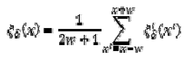
- When doing this computation, w needs to be large enough to prevent ζδ (x) from being completely chaotic but not so large as to ruin the whole point of allowing a varying radial offset. For example, 10° has been observed to work well. Once the function ζδ (x) is computed for each δ, the inner products as defined in the equations at the beginning of this section can readily be computed.
- A strong correlation corresponds to large values of both inner products. The domain of both inner products is [-1, +1] - thus, the net correlation is based on the average of the two inner products. Over a range of +-18°, a reasonable biological limit for cyclotorsion, the net correlation is computed from the average of the two inner products.

- An example of correlation measurements as a function of proposed cyclotorsion angle is shown in
FIG. 9 . - The angle of cyclotorsion is the angle that produces the maximum correlation strength between the extracted features, which corresponds to the global maximum of the curve C in
FIG. 9 . A confidence score τ is computed based on how strong the global maximum is relative to the next highest local maximum, according to the following formula:
- Where r is the ratio between the global maximum and the next largest local maximum present in the correlation function after Gaussian smoothing. For example, in the smoothed correlation function for the plot in
FIG. 9 , the global maximum is at +9.5 degrees, and the next strongest local maximum occurs at -14.5 degrees. From the unsmoothed correlation function, the correlation strengths at these cyclotorsion angles are 0.39 and 0.08 respectively; hence r=4.88 and the resulting confidence score is practically 100. Note that r=1 produces a confidence score of 0, r=2 produces a confidence score of 90%, and it is impossible to obtain a score larger than 100 or less than zero (because r is guaranteed to be greater than or equal to 1). The confidence score is multiplied together with the correlation strength at the global maximum of the unsmoothed correlation function (exactly as seen in the plot above) to obtain a final score which can be used to decide whether the registration was successful or not based on an experimentally determined threshold (see the validation section). This constructs a confidence metric that is both dependent on the absolute value of the correlation strength and the value of the correlation strength relative to the next most convincing peak in the correlation function. It is important for the metric to depend on both of these - one can imagine that if the two highest peaks were of the exact same height it would certainly not be sensible to arbitrarily pick one. Similarly, regardless of the relative score, an absolute correlation strength significantly less than that of all image pairs verified to be correctly registered should not be trusted. - In the left-handed natural coordinate system of the images, the cyclotorsion angle computed tells what value of angle in the topographer image was lined up with the zero angle in the treatment image. In the right-handed coordinate system (where counter clockwise corresponds to positive values of theta), this is equivalent to how the topographer image would be rotated to line up with the treatment image. This is the number needed, because treatment was planned in the frame of reference of the topographer image. Thus, for a cyclotorsion angle of 9.5 degrees, the compass defining the angular coordinate system on the laser system should be rotated by +9.5 degrees. This angle of rotation is calculated by
processor 118 and conveyed to thecontroller 104 which rotates thelaser beam 106. - As shown in
FIGS. 10A-B , there are four regions of particular high correlation at the proposed angle of cyclotorsion. In all four regions it is readily observed that these really do look like the same patches of the iris in both images. In several locations the behavior of the iris under dilation is somewhat nonlinear - see, for example, how the bright fiber just to the right of the leftmost region slightly changes shape between the two images. This illustrates the nature of the registration under deformation problem and sheds some light on why the algorithm used here is the right approach for this type of problem. Deformation in this problem essentially corresponds to iris fibers between the two unwrapped images changing slightly in length, shape, and/or orientation relative to the pupil boundary (hence here we are only discussing the part of the deformation that is not accounted for by the rubber sheet model). Small changes in length, shape, and orientation will in general cause small rotations of the eigenvectors of the structure tensor, which is by no means drastic to a correlation based on the inner product between these eigenvectors. These small deformations are also concentrated in the domain of higher frequencies rather than lower frequencies, and Gabor wavelets mainly extract information from lower frequencies. Thus, both correlation metrics used here are theoretically capable of handling small deformations in image registration. - Some significant statistical validation is possible as well. One example method for doing this is to extend the allowable range of cyclotorsion angles all the way out to ±180° to verify that the global maxima remains at the same location and examine how strong of a maxima it is relative to the correlation strengths of all other cyclotorsion angles. A couple of examples are shown in
FIGS. 11(a)-(b) . In these plots, it is observed that there seems to be a fundamental limit on how strong of a correlation can be obtained from an incorrect cyclotorsion angle. - Accounting for cyclotorsion is of paramount importance in any refractive surgery focused on correcting and/or compensating for astigmatism. An algorithm is proposed that should be able to solve this problem in cataract surgery either in the context of astigmatism-correcting incisions or assistance in toric IOL positioning. One exciting aspect of applying iris registration to cataract surgery is the prospect of releasing the first iris registration algorithm that can accommodate drug induced pupil dilation.
- From the foregoing description, one skilled in the art can readily ascertain the essential characteristics of this invention, and without departing from the scope of the appended claims, can make various changes and/or modifications of the invention to adapt it to various usages and conditions.
Claims (19)
- A laser therapeutic system, comprising:a laser source configured to emit a therapeutic laser beam toward an eye;a laser control system in communication with said laser source, wherein said laser control system is configured to control one or more parameters of said therapeutic laser beam;an analyzer comprising: a light source configured to illuminate said eye;one or more detectors configured to receive reflected light off from said eye and to generate images of an iris of said eye;a memory comprising computer executable instructions; anda processor in communication with said laser control system, said one or more detectors and said memory, said processor configured to receive said images of said iris of said eye and to execute said computer executable instructions characterized in that said instructions comprise a global correlation algorithm capable of precisely determining an iris orientation based upon said images of said iris without the need for singling out particular points in said iris or in said eye, so as to generate a signal based on a correlation function that is defined for said images of said iris of said eye and said signal is able to rotate a coordinate system to correct orientation of said therapeutic laser beam relative so said eye, and wherein said signal is received by said laser control system, which is configured to use said signal to change orientation of said therapeutic laser beam relative to said eye.
- The laser therapeutic system of claim 1, wherein said images comprise a first image that is generated just prior to treatment of said eye by said laser beam and a second image that is generated prior to when said first image is generated.
- The laser therapeutic system of claim 1, wherein said computer executable instructions perform the function of detecting from said images a boundary between an iris and a pupil of said eye.
- The laser therapeutic system of claim 1, wherein said computer executable instructions perform the function of detecting from said images a boundary between an iris and a sclera of said eye.
- The laser therapeutic system of claim 3, wherein said computer executable instructions perform the function of detecting from said images a boundary between an iris and a sclera of said eye.
- The laser therapeutic system of claim 1, wherein said computer executable instructions perform the function of masking out in said images regions of an eyelid of said eye.
- The laser therapeutic system of claim 1, wherein said computer executable instructions perform the function of masking out in said images regions of an eyelash of said eye.
- The laser therapeutic system of claim 1, wherein said computer executable instructions perform the function of filtering and unwrapping an image of an iris of said eye.
- The laser therapeutic system of claim 1, wherein said computer executable instructions perform the function of converting said images from pixel value representation to a feature-based representation.
- The laser therapeutic system of claim 1, wherein said computer executable instructions perform the function of measuring correlation strength as a function of proposed cyclotorsion angle based on said images.
- A method of adjusting an orientation of a therapeutic laser beam in a therapeutic laser system, comprising:providing a first image of an iris of an eye based at a first time;providing a second image of said iris of said eye at a second time;positioning a laser source relative to said eye, wherein said laser source is configured to generate a therapeutic laser beam, wherein said first time is just prior to said therapeutic laser beam being directed to said eye and said second time is prior to said first time;characterized inrotating a coordinate system based on a correlation function that is defined for said first and second images of said iris of said eye to correct orientation of said laser source relative to said eye, said correlation function based upon precisely determining iris orientations without the need for singling out particular points in said iris or said eye.
- The method of claim 11, further comprising detecting from said first and second images a boundary between an iris and a pupil of said eye.
- The method of claim 11, further comprising detecting from said first and second images a boundary between an iris and a sclera of said eye.
- The method of claim 12, further comprising detecting from said first and second images a boundary between an iris and a sclera of said eye.
- The method of claim 11, further comprising masking out in said first and second images regions of an eyelid of said eye.
- The method of claim 11, further comprising masking out in said first and second images regions of an eyelash of said eye.
- The method of claim 11, further comprising filtering and unwrapping an image of an iris of said eye.
- The method of claim 11, further comprising converting said images from pixel value representation to a feature based representation.
- The method of claim 11, further comprising measuring correlation strength as a function of proposed cyclotorsion angle based on said first and second images.
Priority Applications (5)
| Application Number | Priority Date | Filing Date | Title |
|---|---|---|---|
| EP25169120.0A EP4578429A3 (en) | 2013-10-15 | 2014-08-26 | Iris registration method and system |
| EP22168758.5A EP4049636B1 (en) | 2013-10-15 | 2014-08-26 | Iris registration system |
| EP23204900.7A EP4285879A3 (en) | 2013-10-15 | 2014-08-26 | Iris registration method and system |
| EP22168759.3A EP4049637B1 (en) | 2013-10-15 | 2014-08-26 | Iris registration method |
| EP24160287.9A EP4353207B1 (en) | 2013-10-15 | 2014-08-26 | Iris registration method |
Applications Claiming Priority (1)
| Application Number | Priority Date | Filing Date | Title |
|---|---|---|---|
| US201361891149P | 2013-10-15 | 2013-10-15 |
Related Child Applications (7)
| Application Number | Title | Priority Date | Filing Date |
|---|---|---|---|
| EP24160287.9A Division EP4353207B1 (en) | 2013-10-15 | 2014-08-26 | Iris registration method |
| EP22168759.3A Division EP4049637B1 (en) | 2013-10-15 | 2014-08-26 | Iris registration method |
| EP22168759.3A Division-Into EP4049637B1 (en) | 2013-10-15 | 2014-08-26 | Iris registration method |
| EP25169120.0A Division EP4578429A3 (en) | 2013-10-15 | 2014-08-26 | Iris registration method and system |
| EP22168758.5A Division EP4049636B1 (en) | 2013-10-15 | 2014-08-26 | Iris registration system |
| EP22168758.5A Division-Into EP4049636B1 (en) | 2013-10-15 | 2014-08-26 | Iris registration system |
| EP23204900.7A Division EP4285879A3 (en) | 2013-10-15 | 2014-08-26 | Iris registration method and system |
Publications (2)
| Publication Number | Publication Date |
|---|---|
| EP2862548A1 EP2862548A1 (en) | 2015-04-22 |
| EP2862548B1 true EP2862548B1 (en) | 2022-06-01 |
Family
ID=51398533
Family Applications (6)
| Application Number | Title | Priority Date | Filing Date |
|---|---|---|---|
| EP22168759.3A Active EP4049637B1 (en) | 2013-10-15 | 2014-08-26 | Iris registration method |
| EP14182248.6A Active EP2862548B1 (en) | 2013-10-15 | 2014-08-26 | Iris registration method and system |
| EP25169120.0A Pending EP4578429A3 (en) | 2013-10-15 | 2014-08-26 | Iris registration method and system |
| EP23204900.7A Pending EP4285879A3 (en) | 2013-10-15 | 2014-08-26 | Iris registration method and system |
| EP24160287.9A Active EP4353207B1 (en) | 2013-10-15 | 2014-08-26 | Iris registration method |
| EP22168758.5A Active EP4049636B1 (en) | 2013-10-15 | 2014-08-26 | Iris registration system |
Family Applications Before (1)
| Application Number | Title | Priority Date | Filing Date |
|---|---|---|---|
| EP22168759.3A Active EP4049637B1 (en) | 2013-10-15 | 2014-08-26 | Iris registration method |
Family Applications After (4)
| Application Number | Title | Priority Date | Filing Date |
|---|---|---|---|
| EP25169120.0A Pending EP4578429A3 (en) | 2013-10-15 | 2014-08-26 | Iris registration method and system |
| EP23204900.7A Pending EP4285879A3 (en) | 2013-10-15 | 2014-08-26 | Iris registration method and system |
| EP24160287.9A Active EP4353207B1 (en) | 2013-10-15 | 2014-08-26 | Iris registration method |
| EP22168758.5A Active EP4049636B1 (en) | 2013-10-15 | 2014-08-26 | Iris registration system |
Country Status (5)
| Country | Link |
|---|---|
| US (3) | US11090190B2 (en) |
| EP (6) | EP4049637B1 (en) |
| CN (1) | CN104573620B (en) |
| ES (3) | ES2924383T3 (en) |
| WO (1) | WO2016018864A1 (en) |
Families Citing this family (27)
| Publication number | Priority date | Publication date | Assignee | Title |
|---|---|---|---|---|
| US10842675B2 (en) | 2006-01-20 | 2020-11-24 | Lensar, Inc. | System and method for treating the structure of the human lens with a laser |
| US11090190B2 (en) | 2013-10-15 | 2021-08-17 | Lensar, Inc. | Iris registration method and system |
| US10213340B2 (en) | 2006-01-20 | 2019-02-26 | Lensar, Inc. | Methods and systems to provide excluded defined zones for increasing accommodative amplitude |
| US9889043B2 (en) | 2006-01-20 | 2018-02-13 | Lensar, Inc. | System and apparatus for delivering a laser beam to the lens of an eye |
| US10772499B2 (en) | 2009-07-25 | 2020-09-15 | Lensar, Inc. | System and method for measuring tilt |
| WO2011151812A1 (en) | 2010-05-10 | 2011-12-08 | Ramot At Tel-Aviv University Ltd. | System for treating glaucoma by directing electromagnetic energy to the limbal area of an eye |
| US11771596B2 (en) | 2010-05-10 | 2023-10-03 | Ramot At Tel-Aviv University Ltd. | System and method for treating an eye |
| WO2012051490A1 (en) | 2010-10-15 | 2012-04-19 | Lensar, Inc. | System and method of scan controlled illumination of structures within an eye |
| US9844465B2 (en) | 2013-07-29 | 2017-12-19 | Lensar, Inc. | Second pass femtosecond laser for incomplete laser full or partial thickness corneal incisions |
| US10146997B2 (en) | 2015-08-21 | 2018-12-04 | Magic Leap, Inc. | Eyelid shape estimation using eye pose measurement |
| KR102726941B1 (en) * | 2015-08-21 | 2024-11-05 | 매직 립, 인코포레이티드 | Eyelid shape estimation |
| AU2016340222B2 (en) | 2015-10-16 | 2021-07-01 | Magic Leap, Inc. | Eye pose identification using eye features |
| US12533261B2 (en) * | 2016-09-12 | 2026-01-27 | Lensar, Inc. | Laser methods and systems for the aligned insertion of devices into a structure of the eye |
| CN107368725B (en) * | 2017-06-16 | 2020-04-10 | Oppo广东移动通信有限公司 | Iris recognition method, electronic device, and computer-readable storage medium |
| WO2019169372A1 (en) | 2018-03-02 | 2019-09-06 | Lensar, Inc. | Laser methods and systems for addressing, mitigating and reversing presbyopia |
| IL279749B2 (en) | 2018-07-02 | 2024-04-01 | Belkin Vision Ltd | Direct selective laser trabeculoplasty |
| WO2020089737A1 (en) | 2018-10-28 | 2020-05-07 | Belkin Laser Ltd. | Protection for direct selective laser trabeculoplasty |
| JP2023519074A (en) | 2020-01-03 | 2023-05-10 | レンサー インク | Method and system for combined sonic and laser application to the eye |
| CN115666464B (en) | 2020-07-19 | 2026-04-14 | 贝尔金视觉有限公司 | Automatic capsulotomy |
| US12564517B2 (en) | 2020-10-26 | 2026-03-03 | Belvin Vision Ltd. | Avoiding blood vessels during direct selective laser trabeculoplasty |
| AU2021403810B2 (en) * | 2020-12-16 | 2026-01-29 | Alcon Inc. | Adjusting laser pulses to compensate for interfering objects |
| USD975116S1 (en) * | 2021-01-01 | 2023-01-10 | Lensar, Inc. | Display screen with graphical user interface for a laser-phacoemulsification system |
| EP4197428B1 (en) * | 2021-12-20 | 2026-05-20 | Ziemer Ophthalmic Systems AG | OPTHALMOLOGICAL TREATMENT DEVICE FOR DETERMINING THE ANGLE OF AN EYE |
| US12611101B2 (en) | 2022-10-11 | 2026-04-28 | Belkin Vision Ltd. | Gonioscopic laser surgery |
| CN115393350B (en) * | 2022-10-26 | 2023-06-09 | 广东麦特维逊医学研究发展有限公司 | Iris positioning method |
| EP4788276A1 (en) * | 2023-10-08 | 2026-08-12 | AMO Development, LLC | Iris registration method in cataract surgery for astigmatic management |
| US20260069143A1 (en) * | 2024-09-10 | 2026-03-12 | Alcon Inc. | Transition edge based eye registration |
Family Cites Families (56)
| Publication number | Priority date | Publication date | Assignee | Title |
|---|---|---|---|---|
| US4538608A (en) | 1984-03-23 | 1985-09-03 | Esperance Jr Francis A L | Method and apparatus for removing cataractous lens tissue by laser radiation |
| US4764930A (en) | 1988-01-27 | 1988-08-16 | Intelligent Surgical Lasers | Multiwavelength laser source |
| US4901718A (en) | 1988-02-02 | 1990-02-20 | Intelligent Surgical Lasers | 3-Dimensional laser beam guidance system |
| US4907586A (en) | 1988-03-31 | 1990-03-13 | Intelligent Surgical Lasers | Method for reshaping the eye |
| US5098426A (en) | 1989-02-06 | 1992-03-24 | Phoenix Laser Systems, Inc. | Method and apparatus for precision laser surgery |
| US6099522A (en) | 1989-02-06 | 2000-08-08 | Visx Inc. | Automated laser workstation for high precision surgical and industrial interventions |
| DE69114790T2 (en) | 1990-08-20 | 1996-04-18 | Sony Corp | Direct view picture display device. |
| US5291560A (en) | 1991-07-15 | 1994-03-01 | Iri Scan Incorporated | Biometric personal identification system based on iris analysis |
| US6322556B1 (en) | 1991-10-30 | 2001-11-27 | Arlene E. Gwon | Method of laser photoablation of lenticular tissue for the correction of vision problems |
| US20020103478A1 (en) | 1991-10-30 | 2002-08-01 | Gwon Arlene E. | Method of laser photoablation of lenticular tissue for the correction of vision problems |
| US6325792B1 (en) | 1991-11-06 | 2001-12-04 | Casimir A. Swinger | Ophthalmic surgical laser and method |
| US5439462A (en) | 1992-02-25 | 1995-08-08 | Intelligent Surgical Lasers | Apparatus for removing cataractous material |
| US5246435A (en) | 1992-02-25 | 1993-09-21 | Intelligent Surgical Lasers | Method for removing cataractous material |
| DE69533903T2 (en) | 1994-08-18 | 2005-12-08 | Carl Zeiss Meditec Ag | Surgical apparatus controlled by optical coherence tomography |
| US5480396A (en) | 1994-12-09 | 1996-01-02 | Simon; Gabriel | Laser beam ophthalmological surgery method and apparatus |
| US7655002B2 (en) | 1996-03-21 | 2010-02-02 | Second Sight Laser Technologies, Inc. | Lenticular refractive surgery of presbyopia, other refractive errors, and cataract retardation |
| US6197018B1 (en) | 1996-08-12 | 2001-03-06 | O'donnell, Jr. Francis E. | Laser method for restoring accommodative potential |
| DE19814095C2 (en) | 1998-03-30 | 2003-08-14 | Zeiss Carl Jena Gmbh | Method and arrangement for checking and controlling the treatment parameters on an ophthalmic treatment device |
| DE19950790A1 (en) * | 1999-10-21 | 2001-06-21 | Technolas Gmbh | Eye refractive profile developing method for ophthalmic refractive surgery, involves developing refractive course of treatment of eye from determined corneal topography and wavefront aberration |
| JP3679331B2 (en) | 2001-01-25 | 2005-08-03 | 株式会社エクスプローラ | Refractive correction device |
| WO2003102498A1 (en) | 2002-05-30 | 2003-12-11 | Visx, Inc. | “tracking torsional eye orientation and position” |
| US7467869B2 (en) | 2003-04-11 | 2008-12-23 | Bausch & Lomb Incorporated | System and method for acquiring data and aligning and tracking of an eye |
| US20050137586A1 (en) * | 2003-12-23 | 2005-06-23 | Gray Gary P. | Hybrid eye tracking system and associated methods |
| US8394084B2 (en) | 2005-01-10 | 2013-03-12 | Optimedica Corporation | Apparatus for patterned plasma-mediated laser trephination of the lens capsule and three dimensional phaco-segmentation |
| JP4664147B2 (en) * | 2005-07-29 | 2011-04-06 | 株式会社山武 | Iris authentication device |
| US7934833B2 (en) | 2005-12-22 | 2011-05-03 | Alcon Refractivehorizons, Inc. | Image alignment system for use in laser ablation treatment of the cornea |
| US10213340B2 (en) | 2006-01-20 | 2019-02-26 | Lensar, Inc. | Methods and systems to provide excluded defined zones for increasing accommodative amplitude |
| US9889043B2 (en) | 2006-01-20 | 2018-02-13 | Lensar, Inc. | System and apparatus for delivering a laser beam to the lens of an eye |
| US8262646B2 (en) | 2006-01-20 | 2012-09-11 | Lensar, Inc. | System and method for providing the shaped structural weakening of the human lens with a laser |
| US11090190B2 (en) | 2013-10-15 | 2021-08-17 | Lensar, Inc. | Iris registration method and system |
| US10709610B2 (en) | 2006-01-20 | 2020-07-14 | Lensar, Inc. | Laser methods and systems for addressing conditions of the lens |
| US10842675B2 (en) | 2006-01-20 | 2020-11-24 | Lensar, Inc. | System and method for treating the structure of the human lens with a laser |
| US9545338B2 (en) | 2006-01-20 | 2017-01-17 | Lensar, Llc. | System and method for improving the accommodative amplitude and increasing the refractive power of the human lens with a laser |
| US7844084B2 (en) | 2006-02-27 | 2010-11-30 | Donald Martin Monro | Rotation compensated iris comparison |
| US8512323B2 (en) * | 2006-09-12 | 2013-08-20 | University Of Florida Research Foundation, Inc. | Devices and methods for computer-assisted surgery |
| US8926600B2 (en) | 2006-11-10 | 2015-01-06 | Amo Manufacturing Usa, Llc | Operator-controlled scanning laser procedure designed for large-area epithelium removal |
| AU2008358827B2 (en) * | 2008-06-30 | 2013-09-26 | Alcon Inc. | Device, method and control program for ophthalmologic, particularly refractive, laser surgery |
| US8480659B2 (en) | 2008-07-25 | 2013-07-09 | Lensar, Inc. | Method and system for removal and replacement of lens material from the lens of an eye |
| US8500723B2 (en) | 2008-07-25 | 2013-08-06 | Lensar, Inc. | Liquid filled index matching device for ophthalmic laser procedures |
| US9226798B2 (en) * | 2008-10-10 | 2016-01-05 | Truevision Systems, Inc. | Real-time surgical reference indicium apparatus and methods for surgical applications |
| US9173717B2 (en) * | 2009-02-20 | 2015-11-03 | Truevision Systems, Inc. | Real-time surgical reference indicium apparatus and methods for intraocular lens implantation |
| ES2757801T3 (en) * | 2009-04-01 | 2020-04-30 | Alcon Inc | Device for treating an eye with laser radiation |
| US8382745B2 (en) | 2009-07-24 | 2013-02-26 | Lensar, Inc. | Laser system and method for astigmatic corrections in association with cataract treatment |
| US8758332B2 (en) | 2009-07-24 | 2014-06-24 | Lensar, Inc. | Laser system and method for performing and sealing corneal incisions in the eye |
| US8617146B2 (en) | 2009-07-24 | 2013-12-31 | Lensar, Inc. | Laser system and method for correction of induced astigmatism |
| CA2769097A1 (en) | 2009-07-24 | 2011-01-27 | Lensar, Inc. | System and method for performing ladar assisted procedures on the lens of an eye |
| JP2013500078A (en) | 2009-07-24 | 2013-01-07 | レンサー, インク. | System and method for irradiating a lens of an eye with a laser irradiation pattern |
| US20110224657A1 (en) * | 2009-09-18 | 2011-09-15 | Amo Development, Llc | Registration of Corneal Flap With Ophthalmic Measurement and/or Treatment Data for Lasik and Other Procedures |
| CN102811685A (en) | 2010-01-29 | 2012-12-05 | 雷萨公司 | Servo controlled docking force device for use in ophthalmic applications |
| EP2531090A4 (en) * | 2010-02-01 | 2014-11-12 | Lensar Inc | MEASUREMENT OF THE PLACIDO RINGS OF THE AXIS OF ASTIGMATISM AND LASER MARKING OF THIS AXIS |
| WO2012051490A1 (en) | 2010-10-15 | 2012-04-19 | Lensar, Inc. | System and method of scan controlled illumination of structures within an eye |
| DE102010054168B4 (en) | 2010-12-12 | 2017-09-07 | Chronos Vision Gmbh | Method, device and program for determining the torsional component of the eye position |
| US10369053B2 (en) | 2013-04-17 | 2019-08-06 | Optimedica Corporation | Corneal topography measurements and fiducial mark incisions in laser surgical procedures |
| EP4555982A3 (en) | 2013-07-29 | 2025-07-30 | Lensar, Inc. | Patient interface device for ophthalmic laser procedures |
| CN109843205B (en) | 2016-04-07 | 2022-04-05 | 雷萨公司 | Patient engagement device for laser methods and systems |
| US12533261B2 (en) | 2016-09-12 | 2026-01-27 | Lensar, Inc. | Laser methods and systems for the aligned insertion of devices into a structure of the eye |
-
2014
- 2014-07-28 US US14/444,366 patent/US11090190B2/en active Active
- 2014-08-26 ES ES14182248T patent/ES2924383T3/en active Active
- 2014-08-26 EP EP22168759.3A patent/EP4049637B1/en active Active
- 2014-08-26 EP EP14182248.6A patent/EP2862548B1/en active Active
- 2014-08-26 EP EP25169120.0A patent/EP4578429A3/en active Pending
- 2014-08-26 ES ES24160287T patent/ES3021223T3/en active Active
- 2014-08-26 EP EP23204900.7A patent/EP4285879A3/en active Pending
- 2014-08-26 ES ES22168759T patent/ES2970549T3/en active Active
- 2014-08-26 EP EP24160287.9A patent/EP4353207B1/en active Active
- 2014-08-26 EP EP22168758.5A patent/EP4049636B1/en active Active
- 2014-08-26 CN CN201410425964.0A patent/CN104573620B/en active Active
-
2015
- 2015-07-28 WO PCT/US2015/042381 patent/WO2016018864A1/en not_active Ceased
-
2021
- 2021-07-12 US US17/373,375 patent/US12070419B2/en active Active
-
2024
- 2024-08-26 US US18/815,144 patent/US20250228708A1/en active Pending
Also Published As
| Publication number | Publication date |
|---|---|
| US11090190B2 (en) | 2021-08-17 |
| EP2862548A1 (en) | 2015-04-22 |
| US20150105759A1 (en) | 2015-04-16 |
| ES3021223T3 (en) | 2025-05-26 |
| EP4049636B1 (en) | 2023-09-20 |
| EP4353207A2 (en) | 2024-04-17 |
| ES2924383T3 (en) | 2022-10-06 |
| EP4578429A3 (en) | 2025-07-30 |
| EP4049637A1 (en) | 2022-08-31 |
| EP4353207C0 (en) | 2025-04-09 |
| US20220142816A1 (en) | 2022-05-12 |
| EP4578429A2 (en) | 2025-07-02 |
| EP4285879A2 (en) | 2023-12-06 |
| ES2970549T3 (en) | 2024-05-29 |
| EP4285879A3 (en) | 2024-02-14 |
| US20250228708A1 (en) | 2025-07-17 |
| EP4353207A3 (en) | 2024-07-10 |
| EP4049636A1 (en) | 2022-08-31 |
| CN104573620B (en) | 2019-07-26 |
| EP4353207B1 (en) | 2025-04-09 |
| EP4049637B1 (en) | 2023-11-29 |
| CN104573620A (en) | 2015-04-29 |
| US12070419B2 (en) | 2024-08-27 |
| WO2016018864A1 (en) | 2016-02-04 |
Similar Documents
| Publication | Publication Date | Title |
|---|---|---|
| US20250228708A1 (en) | Iris registration method and system | |
| EP2477587B1 (en) | Registration of corneal flap with ophthalmic measurement and/or treatment data for lasik and other procedures | |
| EP1516156B1 (en) | Tracking torsional eye orientation and position | |
| WO2003053228A2 (en) | Method and apparatus for eye registration | |
| Morley et al. | Computing cyclotorsion in refractive cataract surgery | |
| US20250131576A1 (en) | Pupil detection methods in ophthalmic laser surgery for detecting pupil in eye images captured before and after eye applanation | |
| Morley | Visionary Ophthalmics: Confluence of Computer Vision and Deep Learning for Ophthalmology | |
| Vlachynska et al. | The coordinate system of the eye in cataract surgery: Performance comparison of the circle Hough transform and Daugman’s algorithm |
Legal Events
| Date | Code | Title | Description |
|---|---|---|---|
| PUAI | Public reference made under article 153(3) epc to a published international application that has entered the european phase |
Free format text: ORIGINAL CODE: 0009012 |
|
| 17P | Request for examination filed |
Effective date: 20140826 |
|
| AK | Designated contracting states |
Kind code of ref document: A1 Designated state(s): AL AT BE BG CH CY CZ DE DK EE ES FI FR GB GR HR HU IE IS IT LI LT LU LV MC MK MT NL NO PL PT RO RS SE SI SK SM TR |
|
| AX | Request for extension of the european patent |
Extension state: BA ME |
|
| R17P | Request for examination filed (corrected) |
Effective date: 20151022 |
|
| STAA | Information on the status of an ep patent application or granted ep patent |
Free format text: STATUS: EXAMINATION IS IN PROGRESS |
|
| 17Q | First examination report despatched |
Effective date: 20210408 |
|
| GRAP | Despatch of communication of intention to grant a patent |
Free format text: ORIGINAL CODE: EPIDOSNIGR1 |
|
| STAA | Information on the status of an ep patent application or granted ep patent |
Free format text: STATUS: GRANT OF PATENT IS INTENDED |
|
| INTG | Intention to grant announced |
Effective date: 20211222 |
|
| RIN1 | Information on inventor provided before grant (corrected) |
Inventor name: MORLEY, DUSTIN |
|
| GRAS | Grant fee paid |
Free format text: ORIGINAL CODE: EPIDOSNIGR3 |
|
| GRAA | (expected) grant |
Free format text: ORIGINAL CODE: 0009210 |
|
| STAA | Information on the status of an ep patent application or granted ep patent |
Free format text: STATUS: THE PATENT HAS BEEN GRANTED |
|
| AK | Designated contracting states |
Kind code of ref document: B1 Designated state(s): AL AT BE BG CH CY CZ DE DK EE ES FI FR GB GR HR HU IE IS IT LI LT LU LV MC MK MT NL NO PL PT RO RS SE SI SK SM TR |
|
| REG | Reference to a national code |
Ref country code: GB Ref legal event code: FG4D |
|
| REG | Reference to a national code |
Ref country code: AT Ref legal event code: REF Ref document number: 1494893 Country of ref document: AT Kind code of ref document: T Effective date: 20220615 Ref country code: CH Ref legal event code: EP |
|
| REG | Reference to a national code |
Ref country code: IE Ref legal event code: FG4D |
|
| REG | Reference to a national code |
Ref country code: DE Ref legal event code: R096 Ref document number: 602014083876 Country of ref document: DE |
|
| REG | Reference to a national code |
Ref country code: LT Ref legal event code: MG9D |
|
| REG | Reference to a national code |
Ref country code: NL Ref legal event code: MP Effective date: 20220601 |
|
| REG | Reference to a national code |
Ref country code: ES Ref legal event code: FG2A Ref document number: 2924383 Country of ref document: ES Kind code of ref document: T3 Effective date: 20221006 |
|
| REG | Reference to a national code |
Ref country code: FR Ref legal event code: PLFP Year of fee payment: 9 |
|
| PG25 | Lapsed in a contracting state [announced via postgrant information from national office to epo] |
Ref country code: SE Free format text: LAPSE BECAUSE OF FAILURE TO SUBMIT A TRANSLATION OF THE DESCRIPTION OR TO PAY THE FEE WITHIN THE PRESCRIBED TIME-LIMIT Effective date: 20220601 Ref country code: NO Free format text: LAPSE BECAUSE OF FAILURE TO SUBMIT A TRANSLATION OF THE DESCRIPTION OR TO PAY THE FEE WITHIN THE PRESCRIBED TIME-LIMIT Effective date: 20220901 Ref country code: LT Free format text: LAPSE BECAUSE OF FAILURE TO SUBMIT A TRANSLATION OF THE DESCRIPTION OR TO PAY THE FEE WITHIN THE PRESCRIBED TIME-LIMIT Effective date: 20220601 Ref country code: HR Free format text: LAPSE BECAUSE OF FAILURE TO SUBMIT A TRANSLATION OF THE DESCRIPTION OR TO PAY THE FEE WITHIN THE PRESCRIBED TIME-LIMIT Effective date: 20220601 Ref country code: GR Free format text: LAPSE BECAUSE OF FAILURE TO SUBMIT A TRANSLATION OF THE DESCRIPTION OR TO PAY THE FEE WITHIN THE PRESCRIBED TIME-LIMIT Effective date: 20220902 Ref country code: FI Free format text: LAPSE BECAUSE OF FAILURE TO SUBMIT A TRANSLATION OF THE DESCRIPTION OR TO PAY THE FEE WITHIN THE PRESCRIBED TIME-LIMIT Effective date: 20220601 Ref country code: BG Free format text: LAPSE BECAUSE OF FAILURE TO SUBMIT A TRANSLATION OF THE DESCRIPTION OR TO PAY THE FEE WITHIN THE PRESCRIBED TIME-LIMIT Effective date: 20220901 |
|
| REG | Reference to a national code |
Ref country code: AT Ref legal event code: MK05 Ref document number: 1494893 Country of ref document: AT Kind code of ref document: T Effective date: 20220601 |
|
| PG25 | Lapsed in a contracting state [announced via postgrant information from national office to epo] |
Ref country code: RS Free format text: LAPSE BECAUSE OF FAILURE TO SUBMIT A TRANSLATION OF THE DESCRIPTION OR TO PAY THE FEE WITHIN THE PRESCRIBED TIME-LIMIT Effective date: 20220601 Ref country code: PL Free format text: LAPSE BECAUSE OF FAILURE TO SUBMIT A TRANSLATION OF THE DESCRIPTION OR TO PAY THE FEE WITHIN THE PRESCRIBED TIME-LIMIT Effective date: 20220601 Ref country code: LV Free format text: LAPSE BECAUSE OF FAILURE TO SUBMIT A TRANSLATION OF THE DESCRIPTION OR TO PAY THE FEE WITHIN THE PRESCRIBED TIME-LIMIT Effective date: 20220601 |
|
| PG25 | Lapsed in a contracting state [announced via postgrant information from national office to epo] |
Ref country code: NL Free format text: LAPSE BECAUSE OF FAILURE TO SUBMIT A TRANSLATION OF THE DESCRIPTION OR TO PAY THE FEE WITHIN THE PRESCRIBED TIME-LIMIT Effective date: 20220601 |
|
| PG25 | Lapsed in a contracting state [announced via postgrant information from national office to epo] |
Ref country code: SM Free format text: LAPSE BECAUSE OF FAILURE TO SUBMIT A TRANSLATION OF THE DESCRIPTION OR TO PAY THE FEE WITHIN THE PRESCRIBED TIME-LIMIT Effective date: 20220601 Ref country code: SK Free format text: LAPSE BECAUSE OF FAILURE TO SUBMIT A TRANSLATION OF THE DESCRIPTION OR TO PAY THE FEE WITHIN THE PRESCRIBED TIME-LIMIT Effective date: 20220601 Ref country code: RO Free format text: LAPSE BECAUSE OF FAILURE TO SUBMIT A TRANSLATION OF THE DESCRIPTION OR TO PAY THE FEE WITHIN THE PRESCRIBED TIME-LIMIT Effective date: 20220601 Ref country code: PT Free format text: LAPSE BECAUSE OF FAILURE TO SUBMIT A TRANSLATION OF THE DESCRIPTION OR TO PAY THE FEE WITHIN THE PRESCRIBED TIME-LIMIT Effective date: 20221003 Ref country code: EE Free format text: LAPSE BECAUSE OF FAILURE TO SUBMIT A TRANSLATION OF THE DESCRIPTION OR TO PAY THE FEE WITHIN THE PRESCRIBED TIME-LIMIT Effective date: 20220601 Ref country code: CZ Free format text: LAPSE BECAUSE OF FAILURE TO SUBMIT A TRANSLATION OF THE DESCRIPTION OR TO PAY THE FEE WITHIN THE PRESCRIBED TIME-LIMIT Effective date: 20220601 Ref country code: AT Free format text: LAPSE BECAUSE OF FAILURE TO SUBMIT A TRANSLATION OF THE DESCRIPTION OR TO PAY THE FEE WITHIN THE PRESCRIBED TIME-LIMIT Effective date: 20220601 |
|
| PG25 | Lapsed in a contracting state [announced via postgrant information from national office to epo] |
Ref country code: IS Free format text: LAPSE BECAUSE OF FAILURE TO SUBMIT A TRANSLATION OF THE DESCRIPTION OR TO PAY THE FEE WITHIN THE PRESCRIBED TIME-LIMIT Effective date: 20221001 |
|
| REG | Reference to a national code |
Ref country code: DE Ref legal event code: R097 Ref document number: 602014083876 Country of ref document: DE |
|
| PG25 | Lapsed in a contracting state [announced via postgrant information from national office to epo] |
Ref country code: MC Free format text: LAPSE BECAUSE OF FAILURE TO SUBMIT A TRANSLATION OF THE DESCRIPTION OR TO PAY THE FEE WITHIN THE PRESCRIBED TIME-LIMIT Effective date: 20220601 Ref country code: AL Free format text: LAPSE BECAUSE OF FAILURE TO SUBMIT A TRANSLATION OF THE DESCRIPTION OR TO PAY THE FEE WITHIN THE PRESCRIBED TIME-LIMIT Effective date: 20220601 |
|
| REG | Reference to a national code |
Ref country code: CH Ref legal event code: PL |
|
| PLBE | No opposition filed within time limit |
Free format text: ORIGINAL CODE: 0009261 |
|
| STAA | Information on the status of an ep patent application or granted ep patent |
Free format text: STATUS: NO OPPOSITION FILED WITHIN TIME LIMIT |
|
| PG25 | Lapsed in a contracting state [announced via postgrant information from national office to epo] |
Ref country code: LU Free format text: LAPSE BECAUSE OF NON-PAYMENT OF DUE FEES Effective date: 20220826 Ref country code: LI Free format text: LAPSE BECAUSE OF NON-PAYMENT OF DUE FEES Effective date: 20220831 Ref country code: DK Free format text: LAPSE BECAUSE OF FAILURE TO SUBMIT A TRANSLATION OF THE DESCRIPTION OR TO PAY THE FEE WITHIN THE PRESCRIBED TIME-LIMIT Effective date: 20220601 Ref country code: CH Free format text: LAPSE BECAUSE OF NON-PAYMENT OF DUE FEES Effective date: 20220831 |
|
| REG | Reference to a national code |
Ref country code: BE Ref legal event code: MM Effective date: 20220831 |
|
| 26N | No opposition filed |
Effective date: 20230302 |
|
| PG25 | Lapsed in a contracting state [announced via postgrant information from national office to epo] |
Ref country code: SI Free format text: LAPSE BECAUSE OF FAILURE TO SUBMIT A TRANSLATION OF THE DESCRIPTION OR TO PAY THE FEE WITHIN THE PRESCRIBED TIME-LIMIT Effective date: 20220601 |
|
| P01 | Opt-out of the competence of the unified patent court (upc) registered |
Effective date: 20230530 |
|
| PG25 | Lapsed in a contracting state [announced via postgrant information from national office to epo] |
Ref country code: BE Free format text: LAPSE BECAUSE OF NON-PAYMENT OF DUE FEES Effective date: 20220831 |
|
| PG25 | Lapsed in a contracting state [announced via postgrant information from national office to epo] |
Ref country code: HU Free format text: LAPSE BECAUSE OF FAILURE TO SUBMIT A TRANSLATION OF THE DESCRIPTION OR TO PAY THE FEE WITHIN THE PRESCRIBED TIME-LIMIT; INVALID AB INITIO Effective date: 20140826 |
|
| PG25 | Lapsed in a contracting state [announced via postgrant information from national office to epo] |
Ref country code: CY Free format text: LAPSE BECAUSE OF FAILURE TO SUBMIT A TRANSLATION OF THE DESCRIPTION OR TO PAY THE FEE WITHIN THE PRESCRIBED TIME-LIMIT Effective date: 20220601 |
|
| PG25 | Lapsed in a contracting state [announced via postgrant information from national office to epo] |
Ref country code: MK Free format text: LAPSE BECAUSE OF FAILURE TO SUBMIT A TRANSLATION OF THE DESCRIPTION OR TO PAY THE FEE WITHIN THE PRESCRIBED TIME-LIMIT Effective date: 20220601 |
|
| PG25 | Lapsed in a contracting state [announced via postgrant information from national office to epo] |
Ref country code: TR Free format text: LAPSE BECAUSE OF FAILURE TO SUBMIT A TRANSLATION OF THE DESCRIPTION OR TO PAY THE FEE WITHIN THE PRESCRIBED TIME-LIMIT Effective date: 20220601 |
|
| PG25 | Lapsed in a contracting state [announced via postgrant information from national office to epo] |
Ref country code: MT Free format text: LAPSE BECAUSE OF FAILURE TO SUBMIT A TRANSLATION OF THE DESCRIPTION OR TO PAY THE FEE WITHIN THE PRESCRIBED TIME-LIMIT Effective date: 20220601 |
|
| PG25 | Lapsed in a contracting state [announced via postgrant information from national office to epo] |
Ref country code: BG Free format text: LAPSE BECAUSE OF FAILURE TO SUBMIT A TRANSLATION OF THE DESCRIPTION OR TO PAY THE FEE WITHIN THE PRESCRIBED TIME-LIMIT Effective date: 20220601 |
|
| PG25 | Lapsed in a contracting state [announced via postgrant information from national office to epo] |
Ref country code: BG Free format text: LAPSE BECAUSE OF FAILURE TO SUBMIT A TRANSLATION OF THE DESCRIPTION OR TO PAY THE FEE WITHIN THE PRESCRIBED TIME-LIMIT Effective date: 20220601 |
|
| PGFP | Annual fee paid to national office [announced via postgrant information from national office to epo] |
Ref country code: DE Payment date: 20250725 Year of fee payment: 12 |
|
| PGFP | Annual fee paid to national office [announced via postgrant information from national office to epo] |
Ref country code: IT Payment date: 20250807 Year of fee payment: 12 |
|
| PGFP | Annual fee paid to national office [announced via postgrant information from national office to epo] |
Ref country code: GB Payment date: 20250728 Year of fee payment: 12 |
|
| PGFP | Annual fee paid to national office [announced via postgrant information from national office to epo] |
Ref country code: FR Payment date: 20250725 Year of fee payment: 12 |
|
| PGFP | Annual fee paid to national office [announced via postgrant information from national office to epo] |
Ref country code: IE Payment date: 20250725 Year of fee payment: 12 |
|
| PGFP | Annual fee paid to national office [announced via postgrant information from national office to epo] |
Ref country code: ES Payment date: 20251010 Year of fee payment: 12 |