EP2862528A1 - External skeletal fixator and fixation set - Google Patents
External skeletal fixator and fixation set Download PDFInfo
- Publication number
- EP2862528A1 EP2862528A1 EP13804952.3A EP13804952A EP2862528A1 EP 2862528 A1 EP2862528 A1 EP 2862528A1 EP 13804952 A EP13804952 A EP 13804952A EP 2862528 A1 EP2862528 A1 EP 2862528A1
- Authority
- EP
- European Patent Office
- Prior art keywords
- pin
- permanent magnet
- fixation device
- external fixation
- holding portion
- Prior art date
- Legal status (The legal status is an assumption and is not a legal conclusion. Google has not performed a legal analysis and makes no representation as to the accuracy of the status listed.)
- Granted
Links
- UHOVQNZJYSORNB-UHFFFAOYSA-N c1ccccc1 Chemical compound c1ccccc1 UHOVQNZJYSORNB-UHFFFAOYSA-N 0.000 description 1
Images











Classifications
-
- A—HUMAN NECESSITIES
- A61—MEDICAL OR VETERINARY SCIENCE; HYGIENE
- A61B—DIAGNOSIS; SURGERY; IDENTIFICATION
- A61B17/00—Surgical instruments, devices or methods
- A61B17/56—Surgical instruments or methods for treatment of bones or joints; Devices specially adapted therefor
- A61B17/58—Surgical instruments or methods for treatment of bones or joints; Devices specially adapted therefor for osteosynthesis, e.g. bone plates, screws or setting implements
- A61B17/60—Surgical instruments or methods for treatment of bones or joints; Devices specially adapted therefor for osteosynthesis, e.g. bone plates, screws or setting implements for external osteosynthesis, e.g. distractors, contractors
- A61B17/66—Alignment, compression or distraction mechanisms
-
- A—HUMAN NECESSITIES
- A61—MEDICAL OR VETERINARY SCIENCE; HYGIENE
- A61B—DIAGNOSIS; SURGERY; IDENTIFICATION
- A61B17/00—Surgical instruments, devices or methods
- A61B17/56—Surgical instruments or methods for treatment of bones or joints; Devices specially adapted therefor
- A61B17/58—Surgical instruments or methods for treatment of bones or joints; Devices specially adapted therefor for osteosynthesis, e.g. bone plates, screws or setting implements
- A61B17/60—Surgical instruments or methods for treatment of bones or joints; Devices specially adapted therefor for osteosynthesis, e.g. bone plates, screws or setting implements for external osteosynthesis, e.g. distractors, contractors
- A61B17/64—Devices extending alongside the bones to be positioned
- A61B17/6425—Devices extending alongside the bones to be positioned specially adapted to be fitted across a bone joint
-
- A—HUMAN NECESSITIES
- A61—MEDICAL OR VETERINARY SCIENCE; HYGIENE
- A61B—DIAGNOSIS; SURGERY; IDENTIFICATION
- A61B17/00—Surgical instruments, devices or methods
- A61B2017/00831—Material properties
- A61B2017/00876—Material properties magnetic
-
- A—HUMAN NECESSITIES
- A61—MEDICAL OR VETERINARY SCIENCE; HYGIENE
- A61B—DIAGNOSIS; SURGERY; IDENTIFICATION
- A61B17/00—Surgical instruments, devices or methods
- A61B17/56—Surgical instruments or methods for treatment of bones or joints; Devices specially adapted therefor
- A61B2017/567—Joint mechanisms or joint supports in addition to the natural joints and outside the joint gaps
Definitions
- the present invention relates to external fixation devices and fixation device sets, and more specifically to an external fixation device and a fixation device set used in treating articular cartilage damage.
- Extensive articular cartilage damage is treated typically by making a small hole in the damaged area using a drill or an awl to stimulate bleeding from bone marrow thereby introducing bone marrow mesenchymal cells into the joint. Applying a load, however, to the damaged part soon after the operation poses a risk of damaging still immature tissues.
- Patent Literature 1 discloses an example of an external fixation device which can be utilized in such a treatment of an articular cartilage damage.
- the external fixation device includes ball joints and a gear box, sandwiches the joint and mechanically fixes two sides of the joint in order to protect the damaged part, so that joint bone parts are separated from each other and the damaged part will have a reduced load. Then, with the external fixation device attached, the patient moves the joint.
- Patent Literature 1 includes a large number of parts and has a complicated structure.
- Patent Literature 2 discloses an external fixation device which includes a magnet.
- a pair of magnetic bodies one of which fixed to a first bone portion and the other fixed to a second bone portion, contract to each other when the device is used, and cannot be utilized in treating an articular cartilage damage where the first bone portion and the second bone portion in a joint must be separated from each other.
- a primary object of the present invention is to provide an external fixation device which includes a decreased number of parts and has a simple structure yet is capable of separating a first bone portion and a second bone portion from each other in a joint thereby making possible to effectively treating the articular cartilage damage; and to provide a fixation device set.
- an external fixation device for keeping a first bone portion and a second bone portion separated from each other in a joint, by attaching to a first pin which penetrates the first bone portion and to a second pin which penetrates the second bone portion.
- the device includes a first permanent magnet and a second permanent magnet which are opposed to each other, with their same poles facing each other; a first holding portion which is disposed on a surface of the first permanent magnet, on a side facing away from a surface opposing to the second permanent magnet, and is attached to the first pin; a second holding portion which is disposed on a surface of the second permanent magnet, on a side facing away from a surface opposing to the first permanent magnet, and is attached to the second pin; and a pair of first limiter portions which allow movement of the first permanent magnet and the second permanent magnet in a first direction defined as a direction of their repulsion force by sandwiching the first permanent magnet and the second permanent magnet from a second direction defined as a direction perpendicular to the first direction, and limit movement thereof in the second direction.
- the first permanent magnet and the second permanent magnet are disposed with their same poles opposed to each other, and a pair of first limiter portions sandwich the first permanent magnet and the second permanent magnet. Therefore, the first permanent magnet and the second permanent magnet repulse against each other, moving away from each other in the direction of the repulsion force, i.e., in the first direction.
- the first pin which is connected to the first permanent magnet via the first holding portion, and the second pin which is connected to the second permanent magnet via the second holding portion move away from each other. This makes it possible to move a joint, with its first bone portion and second bone portion kept apart from each other, i.e., with the cartilage part of the cleft between articulations kept open.
- the external fixation device further includes a second limiter portion disposed to connect the pair of first limiter portions to each other to limit movement of the first permanent magnet and the second permanent magnet in a third direction defined as a direction perpendicular to both of the first direction and the second direction.
- a second limiter portion disposed to connect the pair of first limiter portions to each other to limit movement of the first permanent magnet and the second permanent magnet in a third direction defined as a direction perpendicular to both of the first direction and the second direction.
- the second limiter portion includes a magnetic member.
- the arrangement makes it possible to reduce a leakage magnetic field around the external fixation device. Therefore, the arrangement makes it possible to reduce adverse effect to the surrounds.
- the external fixation device includes a ball joint for attaching at least one of the first holding portion and the second holding portion to a corresponding one of the first pin and the second pin.
- at least one of the first holding portion and the second holding portion is attached to the corresponding pin(s) via the ball joint. Therefore, the arrangement allows simultaneous, relative stretching/contracting and pivoting movements between components on the first holding portion side and those on the second holding portion side of the external fixation device.
- the external fixation device is capable of following bending and stretching or pivoting movements of the joint, and the patient can move the joint freely. As a result, the joint can be moved smoothly, with a further reduced load onto the articular cartilage damage area (cartilage part under regeneration), making it possible to treat extensive articular cartilage damage more effectively.
- the second holding portion is connected to the ball joint, whereas, the first holding portion has a through-hole for insertion of the first pin.
- the first holding portion can be attached easily to the first pin by inserting the first pin through the through-hole of the first holding portion, and by attaching the second holding portion to the second pin via the ball joint, the joint can be moved smoothly.
- At least one of the first holding portion and the second holding portion has a through-hole for insertion of the corresponding one of the first pin and the second pin.
- the holding portion is attached easily to the pin.
- the external fixation device includes a slanted sleeve fitted into the through-hole.
- the pin which penetrates the through-hole is oriented in a slanted direction. Therefore, it is possible to insert the pin into an area of the bone portion which has a high density of bone, depending on specific conditions of individual patients.
- the pair of first limiter portions and the first holding portion are integral with each other.
- the arrangement further reduces the number of parts in the external fixation device.
- each of the first permanent magnet and the second permanent magnet is rectangular parallelepiped. In this case, it is possible to obtain a large repulsion force with a simple shape at reduced cost.
- a fixation device set which includes the above-described external fixation device for attaching to the first pin and the second pin on their common one end-side; and a pin fixture for attaching to the first pin and the second pin on their common another end-side.
- the pin fixture includes a fixture main body; a first connecting portion for connecting the fixture main body to the first pin; and a second connecting portion for connecting the fixture main body to the second pin.
- the external fixation device is attached to a common one end-side of the first pin which penetrates the first bone portion and the second pin which penetrates the second bone portion, whereas the pin fixture is attached to the other common end-side of the first pin and the second pin.
- the arrangement reduces unnecessary movement of the first pin and the second pin, thereby reducing damage to the bone portions. This works effectively, especially for patients having a low density of bone.
- the fixation device set which includes a decreased number of parts and has a simple structure yet is capable effectively treating the articular cartilage damage.
- the first connecting portion is pivotable with respect to the fixture main body, whereas the second connecting portion is linearly movable with respect to the fixture main body.
- the first connecting portion is pivotable with respect to the fixture main body, whereas the second connecting portion is linearly movable with respect to the fixture main body.
- a direction indicated by Arrow X i.e., a direction of a repulsion force acting between a first permanent magnet and a second permanent magnet is the first direction
- a direction indicated by Arrow Y i.e., a direction perpendicular to Arrow X direction is the second direction
- a direction indicated by Arrow Z i.e., a direction perpendicular to both of the directions indicated by Arrows X and Y is the third direction.
- an external fixation device 10 includes a frame portion 12.
- the frame portion 12 opens in the first direction and the third direction, is substantially U-shaped, is magnetic, and preferably made of a ferrous material or a magnetic stainless steel such as SS400.
- the frame portion 12 includes a prismatic first holding portion 14; a pair of first limiter portions 16a, 16b which are substantially plate-like and extend from two ends of the first holding portion 14 in a substantially perpendicular direction with respect to the first holding portion 14; and stopper portions 18a, 18b formed at tips of the pair of first limiter portions 16a, 16b respectively.
- the first holding portion 14 has a plurality (two, in the present embodiment) of through-holes 20 extending in the third direction.
- the through-holes 20 will be penetrated by first pins P1 (to be described later).
- the frame portion 12 also has, in its two surfaces which are perpendicular to the third direction, a plurality (five in each surface, in the present embodiment) of screw holes 22 extending in the third direction. Further, each of the stopper portions 18a, 18b has a screw hole 24 penetrating in the first direction.
- the first limiter portions 16a, 16b of the frame portion 12 sandwich a first permanent magnet 32 and a second permanent magnet 34 (both will be described later) from the second direction so as to allow the first permanent magnet 32 and the second permanent magnet 34 to move in the first direction but limit them in movement in the second direction.
- the first limiter portions 16a, 16b have their inner surfaces formed with recesses 26a, 26b respectively.
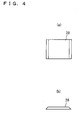
- the recess 26a is fitted with a platy member 28, which is shown in Fig. 4 , is substantially plate-like, and flush with the first limiter portion 16a, whereas the recess 26b is fitted with another platy member 28 flush with the first limiter portion 16b.
- the platy members 28 are nonmagnetic, preferably being formed of a nonmagnetic stainless steel such as SUS304, aluminum, titanium, etc. The platy members 28 prevent magnetic short-circuit between the first permanent magnet 32 and the second permanent magnet 34.
- the first holding portion 14 of the frame portion 12 has an inner surface 30, to which the first permanent magnet 32 is attached. In other words, the first holding portion 14 is on a surface away from an opposing surface 32a of the first permanent magnet 32. Between the first limiter portions 16a, 16b of the frame portion 12, there is disposed the second permanent magnet 34 to oppose to the first permanent magnet 32.
- the first permanent magnet 32 and the second permanent magnet 34 have the same shape of a generally rectangular parallelepiped, and are disposed so that their same poles oppose to each other. As shown in Fig. 2 , in the present embodiment, the first permanent magnet 32 has its N pole on the opposing surface 32a side, and its S pole on the side away from the opposing surface 32a (the first holding portion 14 side).
- the second permanent magnet 34 has its N pole on its opposing surface 34a side, and its S pole on the side away from the opposing surface 34a (on the side facing a second holding portion 36 (which will be described later)).
- the first permanent magnet 32 and the second permanent magnet 34 are provided preferably by an R-Fe-B sintered magnet (R represents a rare-earth element).
- the second holding portion 36 is on a surface away from the opposing surface 34a of the second permanent magnet 34.
- the second holding portion 36 includes a strip-shaped first support member 38 as shown in Fig. 5 , and two second support members 40 as split halves as shown in Fig. 6 .
- the first support member 38 has a hemispherical recess 42, and a plurality (eight, in the present embodiment) of screw holes 44.
- the second support member 40 has a semicircular recess 46, and a plurality (four, in the present embodiment) of screw holes 48 as through holes.
- the first support member 38 and the second support members 40 are magnetic, formed preferably of a ferrous material or a magnetic stainless steel such as SS400.
- the ball joint 50 includes a first shaft portion 52 and a second shaft portion 54.
- the first shaft portion 52 has a ball portion 56 and a female-threaded portion 58.
- the second shaft portion 54 has a tube-like portion 62 which has a through-hole 60; and a male-threaded portion 64.
- the first shaft portion 52 and the second shaft portion 54 are nonmagnetic, preferably being formed of a nonmagnetic stainless steel such as SUS304, aluminum, titanium, etc.
- the through-hole 60 will be penetrated by a second pin P2 (to be described later).
- the ball joint 50 is completed as an assembly.
- the ball portion 56 of the ball joint 50 is inserted into the recess 42 in the first support member 38 of the second holding portion 36, and then the first support member 38 and the two second support members 40 are assembled together to surround an exposed region of the ball portion 56 with two recesses 46. Under this state, screws (not illustrated) are threaded into the screw holes 48, 44.
- two second limiter portions 66 are disposed to cover two openings of the frame portion 12 opening in the third direction.
- the two second limiter portions 66 are placed, connecting the pair of first limiter portions 16a, 16b to each other.
- Each second limiter portion 66 includes a first platy portion 68 and a second platy portion 70. Referring to Fig. 9 and Fig. 10 , the first platy portion 68 and the second platy portion 70 have substantially the same shape except for their thicknesses.
- the first platy portion 68 has a cutout 72; a plurality (two, in the present embodiment 2) of through-holes 74; and a plurality (five, in the present embodiment) of screw holes 76 as through-holes.
- the first platy portion 68 is nonmagnetic, preferably being formed of a nonmagnetic stainless steel such as SUS304, aluminum, titanium, etc.
- the second platy portion 70 has a cutout 78; a plurality (two, in the present embodiment) of through-holes 80; and a plurality (five, in the present embodiment) of screw holes 82 as through-holes.
- the second platy portion 70 is magnetic, and preferably formed of a ferrous material such as SS400, or a magnetic stainless steel.
- the frame portion 12 is sandwiched from the third direction by the two first platy portions 68 to cover two openings of the frame portion 12 opening in the third direction; the second platy portions 70 are placed on the respective first platy portions 68; and then screws 84 (see Fig. 1 ) are threaded into the screw holes 82, 76, 22, whereby the first platy portions 68 and the second platy portions 70 are attached to the frame portion 12.
- the second permanent magnet 34 and therefore the ball joint 50, is movable linearly in a reciprocating fashion in the first direction, whereas the ball joint 50 is pivotable (for example, in Arrow T direction) around the ball portion 56 with respect to the second holding portion 36.
- the external fixation device 10 can allow the joint to move in a direction in which the first pins P1 become twisted with respect to the second pin P2.
- the pin fixture 100 includes a fixture main body 102; a first connecting portion 104 which connect the fixture main body 102 and the first pin P1 (see Fig. 15 ) to each other; and a second connecting portion 106 which connects the fixture main body 102 and the second pin P2 (see Fig. 15 ) to each other.
- the fixture main body 102, the first connecting portion 104 and the second connecting portion 106 are nonmagnetic, preferably being formed of a nonmagnetic stainless steel such as SUS304, aluminum, titanium, etc.
- the fixture main body 102 is substantially J-shaped in a front view (see Fig. 12(a) ), and includes a thick portion 108, and two thin portions 110, 112.
- the thin portion 110 is obtained by forming a recess 114 in the fixture main body 102.
- the thin portion 112 is obtained by forming a recess 116 opening in one direction in the fixture main body 102.
- the thick portion 108 is formed with a through-hole 118
- the thin portion 110 is formed with a screw hole 120 as a through-hole
- the thin portion 112 is formed with a screw hole 122 as a through-hole.
- the first connecting portion 104 is substantially I-shaped in a front view (see Fig. 13(a) ), and includes a thick portion 124 and a thin portion 126.
- the thick portion 124 is formed with a through-hole 128, whereas the thin portion 126 is formed with a through-hole 130 as a long hole.
- the second connecting portion 106 is substantially I-shaped in a front view (see Fig. 14(a) ), and includes a thick portion 132 and a thin portion 134.
- the thick portion 132 is formed with a through-hole 136
- the thin portion 134 is formed with a through-hole 138 as a long hole.
- the screw hole 120 of the fixture main body 102 and the through-hole 130 of the first connecting portion 104 align with each other when the thin portion 126 of the first connecting portion 104 is disposed in the recess 114 of the fixture main body 102, and under this state a bolt 140 is inserted through the through-hole 130 and threaded into the screw hole 120.
- the first connecting portion 104 is pivotable in a direction indicated by Arrow T1 within an angle range of approximately 140 degrees and is linearly movable in a direction indicated by Arrow Y1, with respect to the fixture main body 102.
- the screw hole 122 of the fixture main body 102 and the through-hole 138 of the second connecting portion 106 align with each other when the thin portion 134 of the second connecting portion 106 is fitted into the recess 116 of the fixture main body 102, and under this state a washer 142 is placed in between, a bolt 144 is inserted through the through-hole 138, and threaded into the screw hole 122.
- the second connecting portion 106 is linearly movable with respect to the fixture main body 102 in a direction indicated by Arrow X1.
- a fixation device set S which includes the external fixation device 10 and the pin fixture 100 is attached to a joint as follows:
- description will be made for a case where a first bone portion B on a lower-leg portion side and a second bone portion C on a thigh side are separated from each other, and under this condition, the external fixation device 10 and the pin fixture 100 are attached to a knee joint A to sandwich the knee joint in between so that the external fixation device 10 is on one side of the first bone portion B and the second bone portion C, whereas the pin fixture 100 is on the other side of the first bone portion B and the second bone portion C.
- each of the first pins P1 and the second pin P2 is formed in a rod-like shape, using a material containing titanium which has superb biocompatibility.
- each of the first pins P1 and the second pin P2 has their two end portions formed with a male-thread on their outer surface.
- Fig. 15 shows only one of the two first pins P1.
- three nuts 146, the external fixation device 10 shown in Fig. 1 , and three nuts 146 are attached in this order to the three pins (two first pins P1 and one second pin P2) on one side as viewed from the knee joint A.
- a nut 146 is advanced along each of the two first pins P1 and one second pin P2, to an inner side (side closer to the knee joint A); each of the first pins P1 is inserted through corresponding through-holes (through-holes 20, 74, 80) of the external fixation device 10, while the second pin P2 is inserted through the through-hole 60 in the ball joint 50 of the external fixation device 10, whereby the external fixation device 10 is inserted around the three pins; and further, a nut 146 is inserted around each of the two first pins P1 and the second pin P2.
- the external fixation device 10 is attached to the two first pins P1 and one second pin P2, being sandwiched from two sides by three nuts 146 each on each side. Under this state, the external fixation device 10 is held so as not to come out of the first pins P1 and the second pin P2.
- Each of the first pins P1 and the second pin P2 is rotatable with respect to the external fixation device 10.
- the first pins P1 may be non-rotatable with respect to the external fixation device 10.
- the pin fixture 100 will be attached.
- the pin fixture 100 is attached in the same way as the external fixation device 10.
- three nuts 146, the pin fixture 100 shown in Fig. 11 , and three nuts 146 are attached in this order to the three pins (two first pins P1 and one second pin P2) on the other side as viewed from the knee joint A.
- a nut 146 is advanced along each of the two first pins P1 and one second pin P2, to an inner side (side closer to the knee joint A); each of the first pins P1 is inserted through a corresponding one of the through-holes 118, 128 of the pin fixture 100 while the second pin P2 is inserted through the through-hole 136 in the pin fixture 100, whereby the pin fixture 100 is inserted around the three pins; and further, a nut 146 is inserted around each of the two first pins P1 and the second pin P2.
- the pin fixture 100 is attached to the two first pins P1 and one second pin P2, being sandwiched from two sides by three nuts 146 each on each side. Under this state, the pin fixture 100 is held so as not to come out of the first pins P1 and the second pin P2.
- Each of the first pins P1 and the second pin P2 is rotatable with respect to the pin fixture 100.
- the first pins P1 may be non-rotatable with respect to the pin fixture 100.
- the first permanent magnet 32 and the second permanent magnet 34 are disposed so that their same poles oppose to each other, and the first permanent magnet 32 and the second permanent magnet 34 are sandwiched between the pair of first limiter portions 16a, 16b. Therefore, the first permanent magnet 32 and the second permanent magnet 34 repulse against each other, moving away from each other in the direction of the repulsion force, i.e., in the first direction.
- the first pins P1 which are connected to the first permanent magnet 32 via the first holding portion 14, and the second pin P2 which is connected to the second permanent magnet 34 via the second holding portion 36 move away from each other, making it possible to move the knee joint A while the first bone portion B and the second bone portion C are kept apart from each other, i.e. , with the cartilage part of the knee joint A kept open.
- the repulsion force between the first permanent magnet 32 and the second permanent magnet 34 as described above, it becomes possible to reduce the number of parts and simplify the structure, and therefore, it becomes possible to reduce a load to the damaged area of the articular cartilage (cartilage part under regeneration) and to effectively treat the articular cartilage damage.
- the external fixation device 10 which includes a decreased number of parts and has a simple structure yet is capable of effectively treating the articular cartilage damage. Since the external fixation device 10 can be made at a low cost, made smaller and more compactly than conventional ones, it can reduce burdens on the patient in daily life.
- the second limiter portions 66 include the second platy portions 70 which are magnetic. This reduces a leakage magnetic field around the external fixation device 10. Therefore the arrangement reduces adverse effect to the surrounds.
- the second holding portion 36 is attached to the second pin P2 via the ball joint 50.
- This allows simultaneous, relative stretching/contracting (linear) and pivoting movements between components on the first holding portion 14 side and those on the second holding portion 36 side of the external fixation device 10. Therefore, the external fixation device 10 is capable of following bending/stretching or pivoting movements of the knee joint A, and the patient can move the knee joint A freely. As a result, the knee joint A can be moved smoothly, with a further reduced load onto the articular cartilage damage area (cartilage part under regeneration), making it possible to treat extensive articular cartilage damage more effectively.
- the arrangement that the first pins P1 are inserted through the through-holes 20 in the first holding portion 14 makes it easy to attach the first holding portion 14 to the first pins P1.
- the pair of first limiter portions 16a, 16b and the first holding portion 14 are formed integrally with each other. This further reduces the number of parts of the external fixation device 10.
- Each of the first permanent magnet 32 and the second permanent magnet 34 is rectangular parallelepiped, so a large repulsion force can be obtained with a simple shape at reduced cost.
- the second pin P2 is rotatable with respect to the external fixation device 10. This makes it possible to move the knee joint A more freely.
- the first bone portion B is penetrated by the first pins P1 and the second bone portion C is penetrated by the second pin P2, and the external fixation device 10 is attached on one end-side of the first pins P1 and the second pin P2, whereas the pin fixture 100 is attached on the other end-side thereof.
- the fixation device set S which includes a decreased number of parts and has a simple structure yet is capable effectively treating the articular cartilage damage.
- Fig. 17 shows an external fixation device 10a according to another embodiment.
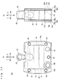
- the external fixation device 10a has an attachable/detachable slanted sleeve 148. Also, the external fixation device 10a has a frame portion 12a, which has the through-hole 20 and a through-hole 20a having a greater diameter than the diameter of the through-hole 20, as through-holes for insertion of the first pins P1. Accordingly, the first platy portion 68a of the second limiter portion 66a have the through-hole 74 and a through-hole 74a which has a greater diameter than the diameter of the through-hole 74, whereas the second platy portion 70a of the second limiter portion 66a has the through-hole 80 and a through-hole 80a which has a greater diameter than the diameter of the through-hole 80.
- the external fixation device 10a has through-holes 20, 74 and 80, each having the same diameter as the respective diameter of the through-holes 20, 74 and 80 in the external fixation device 10. Specifically, using Fig. 17(a) as an example, the through-holes 20a, 74a and 80a are on the left side, whereas the through-holes 20, 74 and 80 are on the right side.
- the slanted sleeve 148 has a cylindrical portion 150, and an annular flange portion 152 formed at an end of the cylindrical portion 150.
- the cylindrical portion 150 and the flange portion 152 are formed with a through-hole 154 which extends in a direction slightly slanted with respect to an axis of the cylindrical portion 150 and flange portion 152.
- the slanted sleeve 148 as described is fitted into the through-holes 80a of the second platy portions 70a, the through-holes 74a of the first platy portions 68a, and the through-hole 20a of the frame portion 12a.
- the through-hole 154 will be penetrated by the first pin P1.
- the slanted sleeve 148 is nonmagnetic, preferably being formed of a nonmagnetic stainless steel such as SUS304, aluminum, titanium, etc. Other arrangements are the same as in the external fixation device 10, so description therefor will not be repeated.
- the slanted sleeve 148 is fitted into the through-holes 80a, 74a and 20a, and therefore it is possible to orient the first pin P1 which is inserted through the through-hole 154 in a slanted direction. This means that it is possible to insert the first pin P1 into an area of the first bone portion B which has a high density of bone, depending on specific conditions of individual patients.
- the first connecting portions 104 is pivotable with respect to the fixture main body 102, and the second connecting portion 106 is linearly movable with respect to the fixture main body 102. Therefore, even if there happens to be variations in the position of the first pins P1 and the second pin P2 on the pin fixture 100 side as viewed from the knee joint A, it is possible to allow for such variations and keep holding the other end-side of the first pins P1 and the second pin P2.
- Fig. 19 there may be an arrangement where the pin fixture 100 is not used, and two of the external fixation devices 10 are attached on two sides of the knee joint A. In this case, it is not necessary to prepare the pin fixture 100.
- a first permanent magnet 32b and a second permanent magnet 34b may be disposed in such a fashion that their N poles oppose to each other and their S poles oppose to each other. Other arrangements are the same as in the external fixation device 10, so description therefor will not be repeated. It should be noted here that in Fig. 20 and thereafter, when an external fixation device is shown, the second limiter portions will not be described in order to avoid complication of the drawing. However, the second limiter portions are included, with appropriate modifications made thereto in accordance with the corresponding external fixation device.
- the external fixation device 10b as described provides the same advantages as offered by the external fixation device 10.
- a ball joint 50a which is longer than the ball joint 50 by, e.g., 30 mm, may be utilized to fit for patients of specific body sizes.
- the ball joint 50a has its second shaft portion 54a has a tube-like portion 62a which has the through-hole 60; a leg portion 62b which extends from the tube-like portion 62a; and the male-threaded portion 64.
- Other arrangements are the same as in the external fixation device 10, so description therefor will not be repeated.
- the external fixation device 10c as described, it is possible to treat tall patients, for example, even if a large gap must be provided between a position to attach the first pins P1 and a position to attach the second pin P2 in the knee joint A.
- the frame portion 12d includes a substantially U-shaped frame main body 156, and two support members 158 as split halves.
- the frame main body 156 has a hemispherical recess 156a, whereas the support member 158 has a semicircular recess 158a.
- the ball portion 56 of the ball joint 50 is inserted into the recess 156a in the frame main body 156, and then the frame main body 156 and the two support members 158 are assembled together to surround an exposed region of the ball portion 56 with the two recesses 158a. Under this state, the frame main body 156 and the two support members 158 are integrally assembled with unillustrated fasteners. Two surfaces of the frame portion 12d which are perpendicular to the third direction are formed with eight (four in each surface) screw holes 22. Other arrangements are the same as in the external fixation device 10, so description therefor will not be repeated.
- the first pins P1 may be inserted through whichever of the through-holes 20d and/or the through-hole 60 of the ball joint 50 depending on situations. This increases convenience.
- the frame portion 12e includes a substantially U-shaped frame main body 160; two support members 162 on two ends; and a support member 164 in a center.
- the frame main body 160 has two hemispherical recesses 160a; the support member 162 has a semicircular recess 162a; and the support member 164 has two end regions each formed with a semicircular recess 164a.
- the two ball portions 56 of the ball joints 50 are inserted into the two recesses 160a in the frame main body 160, and then the frame main body 160, the support member 164 and the two support members 162 are assembled together to surround exposed regions of the ball portions 56 with the recesses 162a and the recess 164a. Under this state, the frame main body 160, the support member 164 and the two support members 162 are integrally assembled with unillustrated fasteners. Two surfaces of the frame main body 160 which are perpendicular to the third direction are formed with eight (four in each surface) screw holes 22. Other arrangements are the same as in the external fixation device 10, so description therefor will not be repeated.
- the ball joint 50 may be attached to a frame portion 12f, and a first holding portion 14f may be formed with two through-holes 166.
- the frame portion 12f includes a substantially U-shaped frame main body 168, and two support members 170 as split halves.
- the frame main body 168 includes first limiter portions 168a, 168b, and a connecting portion 168c which connects the first limiter portions 168a, 168b to each other.
- the connecting portion 168c of the frame main body 168 has a hemispherical recess 168d, whereas the support members 170 have semicircular recesses 170a.
- the ball portion 56 of the ball joint 50 is inserted into the recess 168d in the connecting portion 168c, and then the frame main body 168 and the two support members 170 are assembled together to surround an exposed region of the ball portion 56 with the two recesses 170a. Under this state, the frame main body 168 and the two support members 170 are integrally assembled with unillustrated fasteners.
- the first permanent magnet 32 is disposed on an inner surface of the first holding portion 14f
- the second permanent magnet 34 is disposed on an inner surface of the connecting portion 168c.
- Two surfaces of the frame portion 12f which are perpendicular to the third direction are formed with eight (four in each surface) screw holes 22.
- the first pin P1 is inserted through each of the two through-holes 166 formed in the first holding portion 14f, whereas the second pin P2 is inserted through the through-hole 60 of the ball joint 50 which is attached to the frame portion 12f.
- the connecting portion 168c and the two support members 170 represent the second holding portion. Therefore, in the external fixation device 10f, the first limiter portions 168a, 168b and the second holding portion are formed integrally with each other.
- the external fixation device 10f as described provides substantially the same advantages as offered by the external fixation device 10.
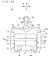
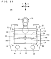
- the external fixation device 10g includes a first permanent magnet 32 and a second permanent magnet 34 which are disposed with their same poles opposed to each other.
- the first holding portion 36a is attached to a surface of the first permanent magnet 32 which faces away from the opposing surface 32a, whereas the second holding portion 36b is attached to a surface of the second permanent magnet 34 which faces away from the opposing surface 34a.
- Each of the first holding portion 36a and the second holding portion 36b is connected to a respective ball joint 50.
- the first permanent magnet 32, the second permanent magnet 34, the first holding portion 36a and the second holding portion 36b described above are sandwiched from their sides (the second direction) by two plate-like first limiter portions 172a, 172b.
- Two surfaces of the first limiter portion 172a which are perpendicular to the third direction are formed with four (two in each surface) screw holes 22.
- two surfaces of the first limiter portion 172b which are perpendicular to the third direction are formed with four (two in each surface) screw holes 22.
- the first pin P1 is inserted through the ball joint 50 on the first permanent magnet 32 side
- the second pin P2 is inserted through the ball joint 50 on the second permanent magnet 34 side.
- the shape of the permanent magnets is not limited to a rectangular parallelepiped. Like an external fixation device 10h shown in Fig. 26 , a first permanent magnet 174 which has a convexed opposing surface 174a and a second permanent magnet 176 which has a concaved opposing surface 176a may be utilized. Other arrangements are the same as in the external fixation device 10, so description therefor will not be repeated.
- the external fixation device 10h as described, it is possible to increase the area of opposing surfaces of the first permanent magnet 174 and the second permanent magnet 176, which makes it possible to further increase the repulsion force.
- both of first limiter portions 177a and 177b of the frame portion 12i may be slanted in one direction. Accordingly, nonmagnetic platy members 178a, 178b disposed on an inner side surface of the frame 12i are also slanted. Other arrangements are the same as in the external fixation device 10, so description therefor will not be repeated.
- the external fixation device 10i it is possible to move the second permanent magnet 34 in a direction slanted from the first direction (oblique direction) with respect to the first permanent magnet 32.
- part of a frame portion 12j may be movable in a left-right direction.
- the frame portion 12j is structured like the frame portion 12 in Fig. 2 but in three pieces, i.e., a first frame 180, a second frame 182 and a third frame 184.
- the first frame 180 and the second frame 182 are connected to each other by a connecting member 186, whereas the first frame 180 and the third frame 184 are connected to each other by a connecting member 186.
- the first frame 180 has its inner side surfaces formed with two platy members 188a; the second frame 182 has its inner side surface formed with a platy member 188b; and the third frame 184 has its inner side surface formed with a platy member 188c.
- the platy members 188a, 188b and 188c are nonmagnetic, preferably being formed of a nonmagnetic stainless steel such as SUS304, aluminum, titanium, etc.
- second limiter portions are attached individually, i.e., for the first frame 180, for the second frame 182 and the third frame 184. Other arrangements are the same as in the external fixation device 10, so description therefor will not be repeated.
- a substantially C-shaped frame portion 12k may be utilized.
- the frame portion 12k includes a first holding portion 190, and a pair of first limiter portions 192a, 192b extending like arcs from two ends of the first holding portion 190.
- the frame portion 12k is formed with a plurality (seven, in the present embodiment) of through-holes 20, and a plurality (eight, in the present embodiment (four in each surface which is perpendicular to the third direction)) of screw holes 22.
- the first holding portion 190 has its inner surface, to which a rectangular parallelepiped first permanent magnet 194 is attached, whereas a second permanent magnet 196 is disposed to oppose the first permanent magnet 194.
- the first permanent magnet 194 and the second permanent magnet 196 are disposed with their same poles opposed to each other.
- the second permanent magnet 196 is held by a second holding portion 198 which is movable in a gap between two end portions of the frame portion 12k.
- the second holding portion 198 includes a first support member 200 attached to the second permanent magnet 196, and two second support members 202 as halves.
- the first support member 200 has a hemispherical recess 200a, whereas each of the second support members 202 has a semicircular recess 202a.
- the ball portion 56 of the ball joint 50 is inserted into a recess 200a in the first support member 200, and then the first support member 200 and the two second support members 202 are assembled together to surround an exposed region of the ball portion 56 with the two recesses 202a. Under this state, the first support member 200 and the two second support members 202 are integrally assembled with unillustrated fasteners. As described above, the ball joint 50 is connected to the second holding portion 198.
- the external fixation device 10k as described, it is possible to obtain a substantially cylindrical device, and it is possible to dispose a plurality of through-holes 20 in an annular pattern in the frame portion 12k. Therefore, it becomes possible to adjust a distance between the first pins P1 and the second pin P2 by selecting the through-holes 20 to insert the first pins P1.
- a through-hole 206 may be formed in a second holding portion 204 which holds the second permanent magnet 34.
- the ball joint 50 is not attached to the second holding portion 204, and the second pin P2 is inserted through the through-hole 206.
- Other arrangements are the same as in the external fixation device 10e shown in Fig. 23 , so description therefor will not be repeated.
- the first permanent magnet 32 is held by the frame portion 12 shown in Fig. 2 ; the second permanent magnet 34 is held by a second holding portion 204 shown in Fig. 30 ; the first pins P1 are inserted through the through-holes 20; and the second pin P2 is inserted through a through-hole 206.
- the present invention need not necessarily include the ball joint 50.
- the number of ball joints attached to the first holding portion, and the number of through-holes formed in the first holding portion may be one or plural.
- a stopper may be provided by a ring member 210 which has a screw hole 208 penetrating in a radial direction and a bolt 212 threaded through the screw hole 208.
- a pin Pa is rod-like, and has flat surfaces 214 on its two end portions.
- the flat surfaces 214 are wider than the place where the external fixation device, the pin fixture 100 and the ring member 210 are attached.
- the ring member 210 is movable axially of the pin Pa even if the bolt 212 threaded through the ring member 210 is in contact with the flat surface 214.
- the ring member 210 attached to the pin Pa is movable axially of the pin Pa as described, the external fixation device and the pin fixture 10 which are attached to the pin Pa are movable axially of the pin Pa, making it possible to move the knee joint A more freely.
- the first pins and the second pin may be provided by a pin Pb which has a head portion 216.
- the frame portion 12 is formed with the screw holes 218 which provides communication between an outer surface of the frame portion 12 and the through-holes 20; and as shown in Fig. 8 , in alternate long and short dash lines, the second shaft portion 54 of the ball joint 50 is formed with a screw hole 220 which provides communication between an outer surface of the tube-like portion 62 and the through-hole 60.
- the pin fixture 100 there may be arrangements that as shown in Fig.
- the fixture main body 102 is formed with a screw hole 222 which provides communication between an outer surface of the thick portion 108 and the through-hole 118; as shown in Fig. 13 , in alternate long and short dash lines, the first connecting portion 104 is formed with a screw hole 224 which provides communication between an outer surface of the thick portion 124 and the through-hole 128; and as shown in Fig. 14 , in alternate long and short dash lines, the second connecting portion 106 is formed with a screw hole 226 which provides communication between an outer surface of the thick portion 132 and the through-hole 136.
- first pins P1 and the second pin P2 may have their end portions provided with resin caps to prevent the external fixation device and the pin fixture 100 from coming off the first pins P1 and the second pin P2.
- the first permanent magnet 32b and the second permanent magnet 34b as shown in Fig. 20 may also be used in the external fixation device shown in Fig. 21 through Fig. 31 .
- the first permanent magnet and the second permanent magnet may be disposed to have their S poles to oppose to each other, with their respective N poles on the outer side.
- the slanted sleeve 148 may be replaced with an ordinary sleeve 228 as shown in Fig. 35 .
- the sleeve 228 has a through-hole 230, which is not slanted with respect to an axis direction of the sleeve 228.
- the sleeve 228 is nonmagnetic, preferably being formed of a nonmagnetic stainless steel such as SUS304, aluminum, titanium, etc.
- the slanted sleeve 148 may be replaced with a hollow tube-like member which has flexibility like resin or rubber.
- a plurality of slanted sleeves may be used in one external fixation device. Also, the slanted sleeve may be fitted into a through-hole formed in the second holding portion.
- the first holding portion and the pair of first limiter portions in the frame portion may be assembled together with fasteners such as bolts.
- the present invention is applicable not only to knee joints but also any other joints such as ankle joints, hip joints, hand joint, elbow joints and finger joints. In these cases, locations and numbers of through-holes and ball joints may be modified depending on the body part.
Landscapes
- Health & Medical Sciences (AREA)
- Orthopedic Medicine & Surgery (AREA)
- Life Sciences & Earth Sciences (AREA)
- Surgery (AREA)
- Medical Informatics (AREA)
- Engineering & Computer Science (AREA)
- Biomedical Technology (AREA)
- Heart & Thoracic Surgery (AREA)
- Nuclear Medicine, Radiotherapy & Molecular Imaging (AREA)
- Molecular Biology (AREA)
- Animal Behavior & Ethology (AREA)
- General Health & Medical Sciences (AREA)
- Public Health (AREA)
- Veterinary Medicine (AREA)
- Surgical Instruments (AREA)
- Prostheses (AREA)
Abstract
Description
- The present invention relates to external fixation devices and fixation device sets, and more specifically to an external fixation device and a fixation device set used in treating articular cartilage damage.
- Extensive articular cartilage damage is treated typically by making a small hole in the damaged area using a drill or an awl to stimulate bleeding from bone marrow thereby introducing bone marrow mesenchymal cells into the joint. Applying a load, however, to the damaged part soon after the operation poses a risk of damaging still immature tissues.
- Patent Literature 1 discloses an example of an external fixation device which can be utilized in such a treatment of an articular cartilage damage. The external fixation device includes ball joints and a gear box, sandwiches the joint and mechanically fixes two sides of the joint in order to protect the damaged part, so that joint bone parts are separated from each other and the damaged part will have a reduced load. Then, with the external fixation device attached, the patient moves the joint.
-
- Patent Literature 1:
JP-A 2002-345837 - Patent Literature 2:
JP-A 2005-245470 - However, the external fixation device disclosed in Patent Literature 1 includes a large number of parts and has a complicated structure.
-
Patent Literature 2 discloses an external fixation device which includes a magnet. However, in this external fixation device, a pair of magnetic bodies, one of which fixed to a first bone portion and the other fixed to a second bone portion, contract to each other when the device is used, and cannot be utilized in treating an articular cartilage damage where the first bone portion and the second bone portion in a joint must be separated from each other. - Therefore, a primary object of the present invention is to provide an external fixation device which includes a decreased number of parts and has a simple structure yet is capable of separating a first bone portion and a second bone portion from each other in a joint thereby making possible to effectively treating the articular cartilage damage; and to provide a fixation device set.
- According to an aspect of the present invention, there is provided an external fixation device for keeping a first bone portion and a second bone portion separated from each other in a joint, by attaching to a first pin which penetrates the first bone portion and to a second pin which penetrates the second bone portion. The device includes a first permanent magnet and a second permanent magnet which are opposed to each other, with their same poles facing each other; a first holding portion which is disposed on a surface of the first permanent magnet, on a side facing away from a surface opposing to the second permanent magnet, and is attached to the first pin; a second holding portion which is disposed on a surface of the second permanent magnet, on a side facing away from a surface opposing to the first permanent magnet, and is attached to the second pin; and a pair of first limiter portions which allow movement of the first permanent magnet and the second permanent magnet in a first direction defined as a direction of their repulsion force by sandwiching the first permanent magnet and the second permanent magnet from a second direction defined as a direction perpendicular to the first direction, and limit movement thereof in the second direction.
- In the present invention, the first permanent magnet and the second permanent magnet are disposed with their same poles opposed to each other, and a pair of first limiter portions sandwich the first permanent magnet and the second permanent magnet. Therefore, the first permanent magnet and the second permanent magnet repulse against each other, moving away from each other in the direction of the repulsion force, i.e., in the first direction. As a result, the first pin which is connected to the first permanent magnet via the first holding portion, and the second pin which is connected to the second permanent magnet via the second holding portion, move away from each other. This makes it possible to move a joint, with its first bone portion and second bone portion kept apart from each other, i.e., with the cartilage part of the cleft between articulations kept open. By utilizing the repulsion force between the first permanent magnet and the second permanent magnet as described above, it becomes possible to reduce the number of parts and simplify the structure, and therefore, it becomes possible to reduce a load to the damaged area of the articular cartilage (cartilage part under regeneration) and to effectively treat the articular cartilage damage. In other words, it becomes possible to obtain an external fixation device which includes a decreased number of parts and has a simple structure yet is capable of effectively treating the articular cartilage damage.
- Preferably, the external fixation device further includes a second limiter portion disposed to connect the pair of first limiter portions to each other to limit movement of the first permanent magnet and the second permanent magnet in a third direction defined as a direction perpendicular to both of the first direction and the second direction. In this case, it becomes possible to limit movement of the first permanent magnet and the second permanent magnet in the third direction which is the direction perpendicular to both of the first direction and the second direction. This prevents the first permanent magnet and the second permanent magnet from becoming twisted to each other, thereby providing a smoother linear reciprocating relative movement between the first permanent magnet and the second permanent magnet.
- Further preferably, the second limiter portion includes a magnetic member. In this case, the arrangement makes it possible to reduce a leakage magnetic field around the external fixation device. Therefore, the arrangement makes it possible to reduce adverse effect to the surrounds.
- Further, preferably, the external fixation device includes a ball joint for attaching at least one of the first holding portion and the second holding portion to a corresponding one of the first pin and the second pin. In this case, at least one of the first holding portion and the second holding portion is attached to the corresponding pin(s) via the ball joint. Therefore, the arrangement allows simultaneous, relative stretching/contracting and pivoting movements between components on the first holding portion side and those on the second holding portion side of the external fixation device. Hence, the external fixation device is capable of following bending and stretching or pivoting movements of the joint, and the patient can move the joint freely. As a result, the joint can be moved smoothly, with a further reduced load onto the articular cartilage damage area (cartilage part under regeneration), making it possible to treat extensive articular cartilage damage more effectively.
- Preferably, the second holding portion is connected to the ball joint, whereas, the first holding portion has a through-hole for insertion of the first pin. In this case, the first holding portion can be attached easily to the first pin by inserting the first pin through the through-hole of the first holding portion, and by attaching the second holding portion to the second pin via the ball joint, the joint can be moved smoothly.
- Further preferably, at least one of the first holding portion and the second holding portion has a through-hole for insertion of the corresponding one of the first pin and the second pin. In this case, by inserting a corresponding pin(s), through the through-hole (s) of at least one of the first holding portion and the second holding portion, the holding portion is attached easily to the pin.
- Further, preferably, the external fixation device includes a slanted sleeve fitted into the through-hole. In this case, by fitting the slanted sleeve into the through-hole of the holding portion, the pin which penetrates the through-hole is oriented in a slanted direction. Therefore, it is possible to insert the pin into an area of the bone portion which has a high density of bone, depending on specific conditions of individual patients.
- Preferably, the pair of first limiter portions and the first holding portion are integral with each other. In this case, the arrangement further reduces the number of parts in the external fixation device.
- Further preferably, each of the first permanent magnet and the second permanent magnet is rectangular parallelepiped. In this case, it is possible to obtain a large repulsion force with a simple shape at reduced cost.
- According to another aspect of the present invention, there is provided a fixation device set which includes the above-described external fixation device for attaching to the first pin and the second pin on their common one end-side; and a pin fixture for attaching to the first pin and the second pin on their common another end-side. The pin fixture includes a fixture main body; a first connecting portion for connecting the fixture main body to the first pin; and a second connecting portion for connecting the fixture main body to the second pin.
- According to the present invention, the external fixation device is attached to a common one end-side of the first pin which penetrates the first bone portion and the second pin which penetrates the second bone portion, whereas the pin fixture is attached to the other common end-side of the first pin and the second pin. The arrangement reduces unnecessary movement of the first pin and the second pin, thereby reducing damage to the bone portions. This works effectively, especially for patients having a low density of bone. As described, it becomes possible to obtain the fixation device set which includes a decreased number of parts and has a simple structure yet is capable effectively treating the articular cartilage damage.
- Preferably, the first connecting portion is pivotable with respect to the fixture main body, whereas the second connecting portion is linearly movable with respect to the fixture main body. In this case, therefore, even if there happens to be variations in the position of the first pin and the second pin on the pin fixture side as viewed from the joint, it is possible to allow for such variations and keep holding the other end-side of the first pin and the second pin.
- The above-described object and other objects, characteristics, aspects and advantages of the present invention will become clearer from the following detailed description of embodiments of the present invention to be made with reference to the attached drawings.
-
-
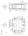
Fig. 1(a) is a front view showing an external fixation device according to an embodiment of the present invention, whereasFig. 1(b) is a side view thereof. -
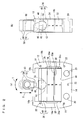
Fig. 2(a) is a front view showing the external fixation device inFig. 1 with its second limiter portions removed, whereasFig. 2(b) is a side view thereof. -
Fig. 3(a) is a front view showing a frame portion,Fig. 3(b) is a plan view thereof, andFig. 3(c) is a side view thereof. -
Fig. 4(a) is a plan view showing a platy member, whereasFig. 4(b) is a front view thereof. -
Fig. 5(a) is a plan view showing a first support member, whereasFig. 5(b) is a front view thereof. -
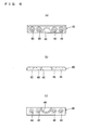
Fig. 6 (a) is a plan view showing a second support member,Fig. 6(b) is a front view thereof, andFig. 6(c) is a bottom view thereof. -
Fig. 7(a) is a front view showing a first shaft portion,Fig. 7(b) is a plan view thereof, andFig. 7(c) is a side thereof. -
Fig. 8(a) is a front view showing a second shaft portion, whereasFig. 8(b) is a side view thereof. -
Fig. 9(a) is a front view showing a first platy portion, whereasFig. 9(b) is a bottom view thereof. -
Fig. 10 (a) is a front view showing a second platy portion, whereasFig. 10(b) is a bottom view thereof. -
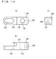
Fig. 11(a) is a front view showing an example of a pin fixture, whereasFig. 11(b) is a side view thereof. -
Fig. 12(a) is a front view showing a fixture main body,Fig. 12 (b) is a side view thereof,Fig. 12 (c) is a bottom view thereof, andFig. 12(d) is a perspective view thereof. -
Fig. 13(a) is a front view showing a first connecting portion,Fig. 13(b) is a bottom view thereof, andFig. 13(c) is a side view thereof. -
Fig. 14(a) is a front view showing a second connecting portion,Fig. 14(b) is a bottom view thereof, andFig. 14(c) is a side view thereof. -
Fig. 15 is an illustrative drawing showing a fixation device set, with an external fixation device attached on one side of a knee joint, and a pin fixture attached to the other side thereof. -
Fig. 16 is an illustrative drawing showing a knee joint and the external fixation device when the knee is bent:Fig. 16 (a) shows a state where the knee is not bent,Fig. 16 (b) shows a state where the knee is bent to 90°, andFig. 16(c) shows a state where the knee is bent to a 120°. -
Fig. 17(a) is a front view showing an external fixation device according to another embodiment of the present invention, whereasFig. 17(b) is a side view thereof. -
Fig. 18 (a) is a front view showing a slanted sleeve, whereasFig. 18(b) is a side view thereof. -
Fig. 19 is an illustrative drawing showing a state where the external fixation devices are attached on both sides of a knee joint. -
Fig. 20 is a front view showing an external fixation device according to still another embodiment of the present invention. -
Fig. 21 is a front view showing an external fixation device according to still another embodiment of the present invention. -
Fig. 22 is a front view showing an external fixation device according to still another embodiment of the present invention. -
Fig. 23 is a front view showing an external fixation device according to still another embodiment of the present invention. -
Fig. 24 is a front view showing an external fixation device according to still another embodiment of the present invention. -
Fig. 25 is a front view showing an external fixation device according to still another embodiment of the present invention. -
Fig. 26 is a front view showing an external fixation device according to still another embodiment of the present invention. -
Fig. 27 is a front view showing an external fixation device according to still another embodiment of the present invention. -
Fig. 28 is a front view showing an external fixation device according to still another embodiment of the present invention. -
Fig. 29 is a front view showing an external fixation device according to still another embodiment of the present invention. -
Fig. 30 is a front view showing an external fixation device according to still another embodiment of the present invention. -
Fig. 31 is a front view showing an external fixation device according to still another embodiment of the present invention. -
Fig. 32 is an illustrative drawing showing another example of the stopper. -
Fig. 33 is an illustrative drawing showing another example of the pin. -
Fig. 34 is an illustrative drawing showing another example of the pin. -
Fig. 35 is a side view showing another example of the sleeve. - Hereinafter, embodiments of the present invention will be described with reference to the drawings.
- Referring to
Fig. 1 through Fig. 3 ,Fig. 17 , andFig. 20 throughFig. 31 , in the embodiments of the present invention, a direction indicated by Arrow X, i.e., a direction of a repulsion force acting between a first permanent magnet and a second permanent magnet is the first direction; a direction indicated by Arrow Y, i.e., a direction perpendicular to Arrow X direction is the second direction; and a direction indicated by Arrow Z, i.e., a direction perpendicular to both of the directions indicated by Arrows X and Y is the third direction. - Referring to
Fig. 1 through Fig. 3 , anexternal fixation device 10 includes aframe portion 12. Theframe portion 12 opens in the first direction and the third direction, is substantially U-shaped, is magnetic, and preferably made of a ferrous material or a magnetic stainless steel such as SS400. Theframe portion 12 includes a prismatic first holdingportion 14; a pair offirst limiter portions portion 14 in a substantially perpendicular direction with respect to the first holdingportion 14; andstopper portions first limiter portions first holding portion 14 has a plurality (two, in the present embodiment) of through-holes 20 extending in the third direction. The through-holes 20 will be penetrated by first pins P1 (to be described later). Theframe portion 12 also has, in its two surfaces which are perpendicular to the third direction, a plurality (five in each surface, in the present embodiment) of screw holes 22 extending in the third direction. Further, each of thestopper portions screw hole 24 penetrating in the first direction. - The
first limiter portions frame portion 12 sandwich a firstpermanent magnet 32 and a second permanent magnet 34 (both will be described later) from the second direction so as to allow the firstpermanent magnet 32 and the secondpermanent magnet 34 to move in the first direction but limit them in movement in the second direction. - As shown in
Fig. 3 , thefirst limiter portions recesses Fig. 2 , therecess 26a is fitted with aplaty member 28, which is shown inFig. 4 , is substantially plate-like, and flush with thefirst limiter portion 16a, whereas therecess 26b is fitted with anotherplaty member 28 flush with thefirst limiter portion 16b. Theplaty members 28 are nonmagnetic, preferably being formed of a nonmagnetic stainless steel such as SUS304, aluminum, titanium, etc. Theplaty members 28 prevent magnetic short-circuit between the firstpermanent magnet 32 and the secondpermanent magnet 34. - The
first holding portion 14 of theframe portion 12 has aninner surface 30, to which the firstpermanent magnet 32 is attached. In other words, the first holdingportion 14 is on a surface away from an opposingsurface 32a of the firstpermanent magnet 32. Between thefirst limiter portions frame portion 12, there is disposed the secondpermanent magnet 34 to oppose to the firstpermanent magnet 32. The firstpermanent magnet 32 and the secondpermanent magnet 34 have the same shape of a generally rectangular parallelepiped, and are disposed so that their same poles oppose to each other. As shown inFig. 2 , in the present embodiment, the firstpermanent magnet 32 has its N pole on the opposingsurface 32a side, and its S pole on the side away from the opposingsurface 32a (the first holdingportion 14 side). Likewise, the secondpermanent magnet 34 has its N pole on its opposingsurface 34a side, and its S pole on the side away from the opposingsurface 34a (on the side facing a second holding portion 36 (which will be described later)). The firstpermanent magnet 32 and the secondpermanent magnet 34 are provided preferably by an R-Fe-B sintered magnet (R represents a rare-earth element). - The
second holding portion 36 is on a surface away from the opposingsurface 34a of the secondpermanent magnet 34. Thesecond holding portion 36 includes a strip-shapedfirst support member 38 as shown inFig. 5 , and twosecond support members 40 as split halves as shown inFig. 6 . Thefirst support member 38 has ahemispherical recess 42, and a plurality (eight, in the present embodiment) of screw holes 44. Thesecond support member 40 has asemicircular recess 46, and a plurality (four, in the present embodiment) of screw holes 48 as through holes. Thefirst support member 38 and thesecond support members 40 are magnetic, formed preferably of a ferrous material or a magnetic stainless steel such as SS400. - As shown in
Fig. 1 andFig. 2 , the second holdingportion 36 is connected to a ball joint 50. The ball joint 50 includes afirst shaft portion 52 and asecond shaft portion 54. Referring toFig. 7 , thefirst shaft portion 52 has aball portion 56 and a female-threadedportion 58. Referring toFig. 8 , thesecond shaft portion 54 has a tube-like portion 62 which has a through-hole 60; and a male-threadedportion 64. Thefirst shaft portion 52 and thesecond shaft portion 54 are nonmagnetic, preferably being formed of a nonmagnetic stainless steel such as SUS304, aluminum, titanium, etc. The through-hole 60 will be penetrated by a second pin P2 (to be described later). As the male-threadedportion 64 is threaded into the female-threadedportion 58, the ball joint 50 is completed as an assembly. Theball portion 56 of the ball joint 50 is inserted into therecess 42 in thefirst support member 38 of the second holdingportion 36, and then thefirst support member 38 and the twosecond support members 40 are assembled together to surround an exposed region of theball portion 56 with tworecesses 46. Under this state, screws (not illustrated) are threaded into the screw holes 48, 44. - Returning to
Fig. 1 , twosecond limiter portions 66 are disposed to cover two openings of theframe portion 12 opening in the third direction. In other words, in order to limit the firstpermanent magnet 32 and the secondpermanent magnet 34 from moving in the third direction, the twosecond limiter portions 66 are placed, connecting the pair offirst limiter portions second limiter portion 66 includes afirst platy portion 68 and asecond platy portion 70. Referring toFig. 9 andFig. 10 , thefirst platy portion 68 and thesecond platy portion 70 have substantially the same shape except for their thicknesses. Thefirst platy portion 68 has acutout 72; a plurality (two, in the present embodiment 2) of through-holes 74; and a plurality (five, in the present embodiment) of screw holes 76 as through-holes. Thefirst platy portion 68 is nonmagnetic, preferably being formed of a nonmagnetic stainless steel such as SUS304, aluminum, titanium, etc. Thesecond platy portion 70 has acutout 78; a plurality (two, in the present embodiment) of through-holes 80; and a plurality (five, in the present embodiment) of screw holes 82 as through-holes. Thesecond platy portion 70 is magnetic, and preferably formed of a ferrous material such as SS400, or a magnetic stainless steel. - The
frame portion 12 is sandwiched from the third direction by the twofirst platy portions 68 to cover two openings of theframe portion 12 opening in the third direction; thesecond platy portions 70 are placed on the respective firstplaty portions 68; and then screws 84 (seeFig. 1 ) are threaded into the screw holes 82, 76, 22, whereby thefirst platy portions 68 and thesecond platy portions 70 are attached to theframe portion 12. - Referring to
Fig. 2 , according to theexternal fixation device 10 as described, the secondpermanent magnet 34, and therefore the ball joint 50, is movable linearly in a reciprocating fashion in the first direction, whereas the ball joint 50 is pivotable (for example, in Arrow T direction) around theball portion 56 with respect to the second holdingportion 36. Thus, when theexternal fixation device 10 is attached to a joint via the first pins P1 and the second pin P2, theexternal fixation device 10 can allow the joint to move in a direction in which the first pins P1 become twisted with respect to the second pin P2. - Returning to
Fig. 1 andFig. 3 , until theexternal fixation device 10 as described thus far is attached to a joint, setscrews 86 which are threaded into the twoscrew holes 24 keep the second holdingportion 36 and the secondpermanent magnet 34 pressed toward the firstpermanent magnet 32. - Next, the
pin fixture 100 will be described with reference toFig. 11 through Fig. 14 . - As shown in
Fig. 11 , thepin fixture 100 includes a fixturemain body 102; a first connectingportion 104 which connect the fixturemain body 102 and the first pin P1 (seeFig. 15 ) to each other; and a second connectingportion 106 which connects the fixturemain body 102 and the second pin P2 (seeFig. 15 ) to each other. The fixturemain body 102, the first connectingportion 104 and the second connectingportion 106 are nonmagnetic, preferably being formed of a nonmagnetic stainless steel such as SUS304, aluminum, titanium, etc. - As shown in
Fig. 12 , the fixturemain body 102 is substantially J-shaped in a front view (seeFig. 12(a) ), and includes athick portion 108, and twothin portions thin portion 110 is obtained by forming arecess 114 in the fixturemain body 102. Thethin portion 112 is obtained by forming arecess 116 opening in one direction in the fixturemain body 102. Thethick portion 108 is formed with a through-hole 118, thethin portion 110 is formed with ascrew hole 120 as a through-hole, and thethin portion 112 is formed with ascrew hole 122 as a through-hole. - As shown in
Fig. 13 , the first connectingportion 104 is substantially I-shaped in a front view (seeFig. 13(a) ), and includes athick portion 124 and athin portion 126. Thethick portion 124 is formed with a through-hole 128, whereas thethin portion 126 is formed with a through-hole 130 as a long hole. - As shown in
Fig. 14 , the second connectingportion 106 is substantially I-shaped in a front view (seeFig. 14(a) ), and includes athick portion 132 and athin portion 134. Thethick portion 132 is formed with a through-hole 136, whereas thethin portion 134 is formed with a through-hole 138 as a long hole. - Referring to
Fig. 11 through Fig. 13 , thescrew hole 120 of the fixturemain body 102 and the through-hole 130 of the first connectingportion 104 align with each other when thethin portion 126 of the first connectingportion 104 is disposed in therecess 114 of the fixturemain body 102, and under this state abolt 140 is inserted through the through-hole 130 and threaded into thescrew hole 120. Being attached as described, the first connectingportion 104 is pivotable in a direction indicated by Arrow T1 within an angle range of approximately 140 degrees and is linearly movable in a direction indicated by Arrow Y1, with respect to the fixturemain body 102. In regard of the pivotal movement of the first connectingportion 104, it is acceptable in actual use, that as far as the first connectingportion 104 is pivotable with respect to the fixturemain body 102 within a ± approximately 25-degree range from a position indicated by solid lines inFig. 11(a) . Further, referring toFig. 14 , thescrew hole 122 of the fixturemain body 102 and the through-hole 138 of the second connectingportion 106 align with each other when thethin portion 134 of the second connectingportion 106 is fitted into therecess 116 of the fixturemain body 102, and under this state awasher 142 is placed in between, abolt 144 is inserted through the through-hole 138, and threaded into thescrew hole 122. Being attached as described, the second connectingportion 106 is linearly movable with respect to the fixturemain body 102 in a direction indicated by Arrow X1. - Referring to
Fig. 15 , a fixation device set S which includes theexternal fixation device 10 and thepin fixture 100 is attached to a joint as follows: Herein, description will be made for a case where a first bone portion B on a lower-leg portion side and a second bone portion C on a thigh side are separated from each other, and under this condition, theexternal fixation device 10 and thepin fixture 100 are attached to a knee joint A to sandwich the knee joint in between so that theexternal fixation device 10 is on one side of the first bone portion B and the second bone portion C, whereas thepin fixture 100 is on the other side of the first bone portion B and the second bone portion C. - First, by means of a drill for example, two through-holes are made in the first bone portion B, and one through-hole as well, in the second bone portion C. Next, the first pins P1 are inserted through the through-holes made in the first bone portion B respectively, whereas the second pin P2 is inserted through the through-hole made in the second bone portion C. It is preferable that each of the first pins P1 and the second pin P2 is formed in a rod-like shape, using a material containing titanium which has superb biocompatibility. In the present embodiment, each of the first pins P1 and the second pin P2 has their two end portions formed with a male-thread on their outer surface.
Fig. 15 shows only one of the two first pins P1. - Then, three
nuts 146, theexternal fixation device 10 shown inFig. 1 , and threenuts 146 are attached in this order to the three pins (two first pins P1 and one second pin P2) on one side as viewed from the knee joint A. In other words, on one side as viewed from the knee joint A, anut 146 is advanced along each of the two first pins P1 and one second pin P2, to an inner side (side closer to the knee joint A); each of the first pins P1 is inserted through corresponding through-holes (through-holes external fixation device 10, while the second pin P2 is inserted through the through-hole 60 in the ball joint 50 of theexternal fixation device 10, whereby theexternal fixation device 10 is inserted around the three pins; and further, anut 146 is inserted around each of the two first pins P1 and the second pin P2. Hence, theexternal fixation device 10 is attached to the two first pins P1 and one second pin P2, being sandwiched from two sides by threenuts 146 each on each side. Under this state, theexternal fixation device 10 is held so as not to come out of the first pins P1 and the second pin P2. Each of the first pins P1 and the second pin P2 is rotatable with respect to theexternal fixation device 10. However, the first pins P1 may be non-rotatable with respect to theexternal fixation device 10. - Thereafter, as shown in
Fig. 1 , the two setscrews 86 which keep the second holdingportion 36 and the secondpermanent magnet 34 pressed toward the firstpermanent magnet 32 are released or removed, as necessary, from theexternal fixation device 10. As a result, due to a repulsion force acting between the firstpermanent magnet 32 and the secondpermanent magnet 34, a force works in a direction to increase a distance between the first pins P1 and the second pin P2. - This expansion/contraction movement of the
external fixation device 10 is observed, to determine if thepin fixture 100 should be attached, anotherexternal fixation device 10 should be attached, or nothing should be made, on the other side as viewed from the knee joint A. - In the present description, the
pin fixture 100 will be attached. - The
pin fixture 100 is attached in the same way as theexternal fixation device 10. - First, three
nuts 146, thepin fixture 100 shown inFig. 11 , and threenuts 146 are attached in this order to the three pins (two first pins P1 and one second pin P2) on the other side as viewed from the knee joint A. In other words, on the other side as viewed from the knee joint A, anut 146 is advanced along each of the two first pins P1 and one second pin P2, to an inner side (side closer to the knee joint A); each of the first pins P1 is inserted through a corresponding one of the through-holes pin fixture 100 while the second pin P2 is inserted through the through-hole 136 in thepin fixture 100, whereby thepin fixture 100 is inserted around the three pins; and further, anut 146 is inserted around each of the two first pins P1 and the second pin P2. Hence, thepin fixture 100 is attached to the two first pins P1 and one second pin P2, being sandwiched from two sides by threenuts 146 each on each side. Under this state, thepin fixture 100 is held so as not to come out of the first pins P1 and the second pin P2. Each of the first pins P1 and the second pin P2 is rotatable with respect to thepin fixture 100. However, the first pins P1 may be non-rotatable with respect to thepin fixture 100. - In the
external fixation device 10 attached to the knee joint A, when the patient is standing upright for example, a repulsion force of approximately 240N (24.5 kgf) is acting between the firstpermanent magnet 32 and the secondpermanent magnet 34. - Description will be made for a case where a knee is being bent with the
external fixation device 10 and thepin fixture 100 attached thereto as described above, with reference toFig. 16(a) through Fig. 16(c) . - As shown in
Fig. 16(a) , when the knee is not bent, the firstpermanent magnet 32 and the secondpermanent magnet 34 are close to each other. Next, when the knee is bent at approximately 90° as shown inFig. 16(b) , the secondpermanent magnet 34 moves away from the firstpermanent magnet 32. Then, when the knee is bent at approximately 120° as shown inFig. 16(c) , the secondpermanent magnet 34 moves further away from the firstpermanent magnet 32. While the knee is being bent from 0° (stretched state) to 120°, the ball joint 50 pivots around theball portion 56 with respect to the second holdingportion 36. As described, the first bone portion B and the second bone portion C are kept apart from each other when the knee is bent. - According to the
external fixation device 10, the firstpermanent magnet 32 and the secondpermanent magnet 34 are disposed so that their same poles oppose to each other, and the firstpermanent magnet 32 and the secondpermanent magnet 34 are sandwiched between the pair offirst limiter portions permanent magnet 32 and the secondpermanent magnet 34 repulse against each other, moving away from each other in the direction of the repulsion force, i.e., in the first direction. As a result, the first pins P1 which are connected to the firstpermanent magnet 32 via the first holdingportion 14, and the second pin P2 which is connected to the secondpermanent magnet 34 via the second holdingportion 36 move away from each other, making it possible to move the knee joint A while the first bone portion B and the second bone portion C are kept apart from each other, i.e. , with the cartilage part of the knee joint A kept open. By utilizing the repulsion force between the firstpermanent magnet 32 and the secondpermanent magnet 34 as described above, it becomes possible to reduce the number of parts and simplify the structure, and therefore, it becomes possible to reduce a load to the damaged area of the articular cartilage (cartilage part under regeneration) and to effectively treat the articular cartilage damage. In other words, it becomes possible to obtain theexternal fixation device 10 which includes a decreased number of parts and has a simple structure yet is capable of effectively treating the articular cartilage damage. Since theexternal fixation device 10 can be made at a low cost, made smaller and more compactly than conventional ones, it can reduce burdens on the patient in daily life. - By providing two
second limiter portions 66 to connect the pair offirst limiter portions permanent magnet 34 in the third direction which is the direction perpendicular to both of the first direction and the second direction, preventing the firstpermanent magnet 32 and the secondpermanent magnet 34 from becoming twisted to each other, thereby providing a smoother linear reciprocating movement of the secondpermanent magnet 34 relative to the firstpermanent magnet 32. Since the firstpermanent magnet 32 and the secondpermanent magnet 34 stay inside a space surrounded by theframe portion 12 and thesecond limiter portions 66, neither the firstpermanent magnet 32 nor the secondpermanent magnet 34 will rub against or pinch the patient's skin. - The
second limiter portions 66 include thesecond platy portions 70 which are magnetic. This reduces a leakage magnetic field around theexternal fixation device 10. Therefore the arrangement reduces adverse effect to the surrounds. - The
second holding portion 36 is attached to the second pin P2 via the ball joint 50. This allows simultaneous, relative stretching/contracting (linear) and pivoting movements between components on the first holdingportion 14 side and those on the second holdingportion 36 side of theexternal fixation device 10. Therefore, theexternal fixation device 10 is capable of following bending/stretching or pivoting movements of the knee joint A, and the patient can move the knee joint A freely. As a result, the knee joint A can be moved smoothly, with a further reduced load onto the articular cartilage damage area (cartilage part under regeneration), making it possible to treat extensive articular cartilage damage more effectively. - The arrangement that the first pins P1 are inserted through the through-
holes 20 in the first holdingportion 14 makes it easy to attach the first holdingportion 14 to the first pins P1. - The pair of
first limiter portions portion 14 are formed integrally with each other. This further reduces the number of parts of theexternal fixation device 10. - Each of the first
permanent magnet 32 and the secondpermanent magnet 34 is rectangular parallelepiped, so a large repulsion force can be obtained with a simple shape at reduced cost. - The second pin P2 is rotatable with respect to the
external fixation device 10. This makes it possible to move the knee joint A more freely. - The first bone portion B is penetrated by the first pins P1 and the second bone portion C is penetrated by the second pin P2, and the
external fixation device 10 is attached on one end-side of the first pins P1 and the second pin P2, whereas thepin fixture 100 is attached on the other end-side thereof. This reduces unnecessary movement of the first pins P1 and the second pin P2, thereby reducing damage to the first bone portion B and the second bone portion C. This works effectively, especially for patients having a low density of bone. As described, it becomes possible to obtain the fixation device set S which includes a decreased number of parts and has a simple structure yet is capable effectively treating the articular cartilage damage. -
Fig. 17 shows anexternal fixation device 10a according to another embodiment. - The
external fixation device 10a has an attachable/detachableslanted sleeve 148. Also, theexternal fixation device 10a has aframe portion 12a, which has the through-hole 20 and a through-hole 20a having a greater diameter than the diameter of the through-hole 20, as through-holes for insertion of the first pins P1. Accordingly, thefirst platy portion 68a of thesecond limiter portion 66a have the through-hole 74 and a through-hole 74a which has a greater diameter than the diameter of the through-hole 74, whereas thesecond platy portion 70a of thesecond limiter portion 66a has the through-hole 80 and a through-hole 80a which has a greater diameter than the diameter of the through-hole 80. Theexternal fixation device 10a has through-holes holes external fixation device 10. Specifically, usingFig. 17(a) as an example, the through-holes holes - Referring to
Fig. 18 , theslanted sleeve 148 has acylindrical portion 150, and anannular flange portion 152 formed at an end of thecylindrical portion 150. Thecylindrical portion 150 and theflange portion 152 are formed with a through-hole 154 which extends in a direction slightly slanted with respect to an axis of thecylindrical portion 150 andflange portion 152. Theslanted sleeve 148 as described is fitted into the through-holes 80a of thesecond platy portions 70a, the through-holes 74a of thefirst platy portions 68a, and the through-hole 20a of theframe portion 12a. The through-hole 154 will be penetrated by the first pin P1. Theslanted sleeve 148 is nonmagnetic, preferably being formed of a nonmagnetic stainless steel such as SUS304, aluminum, titanium, etc. Other arrangements are the same as in theexternal fixation device 10, so description therefor will not be repeated. - According to the
external fixation device 10a as described, theslanted sleeve 148 is fitted into the through-holes hole 154 in a slanted direction. This means that it is possible to insert the first pin P1 into an area of the first bone portion B which has a high density of bone, depending on specific conditions of individual patients. - The first connecting
portions 104 is pivotable with respect to the fixturemain body 102, and the second connectingportion 106 is linearly movable with respect to the fixturemain body 102. Therefore, even if there happens to be variations in the position of the first pins P1 and the second pin P2 on thepin fixture 100 side as viewed from the knee joint A, it is possible to allow for such variations and keep holding the other end-side of the first pins P1 and the second pin P2. - As shown in
Fig. 19 , there may be an arrangement where thepin fixture 100 is not used, and two of theexternal fixation devices 10 are attached on two sides of the knee joint A. In this case, it is not necessary to prepare thepin fixture 100. - Like an
external fixation device 10b shown inFig. 20 , a firstpermanent magnet 32b and a secondpermanent magnet 34b may be disposed in such a fashion that their N poles oppose to each other and their S poles oppose to each other. Other arrangements are the same as in theexternal fixation device 10, so description therefor will not be repeated. It should be noted here that inFig. 20 and thereafter, when an external fixation device is shown, the second limiter portions will not be described in order to avoid complication of the drawing. However, the second limiter portions are included, with appropriate modifications made thereto in accordance with the corresponding external fixation device. - The
external fixation device 10b as described provides the same advantages as offered by theexternal fixation device 10. - Like an
external fixation device 10c shown inFig. 21 , a ball joint 50a which is longer than the ball joint 50 by, e.g., 30 mm, may be utilized to fit for patients of specific body sizes. The ball joint 50a has itssecond shaft portion 54a has a tube-like portion 62a which has the through-hole 60; aleg portion 62b which extends from the tube-like portion 62a; and the male-threadedportion 64. Other arrangements are the same as in theexternal fixation device 10, so description therefor will not be repeated. - According to the
external fixation device 10c as described, it is possible to treat tall patients, for example, even if a large gap must be provided between a position to attach the first pins P1 and a position to attach the second pin P2 in the knee joint A. - Like an
external fixation device 10d shown inFig. 22 , there may be an arrangement where aframe portion 12d is not only formed with two through-holes 20d but also have a ball joint 50 attached thereto. In this case, theframe portion 12d includes a substantially U-shaped framemain body 156, and twosupport members 158 as split halves. The framemain body 156 has ahemispherical recess 156a, whereas thesupport member 158 has asemicircular recess 158a. Theball portion 56 of the ball joint 50 is inserted into therecess 156a in the framemain body 156, and then the framemain body 156 and the twosupport members 158 are assembled together to surround an exposed region of theball portion 56 with the tworecesses 158a. Under this state, the framemain body 156 and the twosupport members 158 are integrally assembled with unillustrated fasteners. Two surfaces of theframe portion 12d which are perpendicular to the third direction are formed with eight (four in each surface) screw holes 22. Other arrangements are the same as in theexternal fixation device 10, so description therefor will not be repeated. - According to the
external fixation device 10d as described, since theframe portion 12d is provided with the through-holes 20d and the ball joint 50, the first pins P1 may be inserted through whichever of the through-holes 20d and/or the through-hole 60 of the ball joint 50 depending on situations. This increases convenience. - Like an
external fixation device 10e shown inFig. 23 , there may be an arrangement that not only the ball joint 50 is attached to the second holdingportion 36 but also twoball joints 50 are attached to aframe portion 12e. In this case, theframe portion 12e includes a substantially U-shaped framemain body 160; twosupport members 162 on two ends; and asupport member 164 in a center. The framemain body 160 has twohemispherical recesses 160a; thesupport member 162 has asemicircular recess 162a; and thesupport member 164 has two end regions each formed with asemicircular recess 164a. The twoball portions 56 of the ball joints 50 are inserted into the tworecesses 160a in the framemain body 160, and then the framemain body 160, thesupport member 164 and the twosupport members 162 are assembled together to surround exposed regions of theball portions 56 with therecesses 162a and therecess 164a. Under this state, the framemain body 160, thesupport member 164 and the twosupport members 162 are integrally assembled with unillustrated fasteners. Two surfaces of the framemain body 160 which are perpendicular to the third direction are formed with eight (four in each surface) screw holes 22. Other arrangements are the same as in theexternal fixation device 10, so description therefor will not be repeated. - According to the
external fixation device 10e as described, freedom of movement of the knee joint A is further improved. - Like an
external fixation device 10f shown inFig. 24 , the ball joint 50 may be attached to aframe portion 12f, and afirst holding portion 14f may be formed with two through-holes 166. In this case, theframe portion 12f includes a substantially U-shaped framemain body 168, and twosupport members 170 as split halves. The framemain body 168 includesfirst limiter portions portion 168c which connects thefirst limiter portions portion 168c of the framemain body 168 has ahemispherical recess 168d, whereas thesupport members 170 havesemicircular recesses 170a. Theball portion 56 of the ball joint 50 is inserted into therecess 168d in the connectingportion 168c, and then the framemain body 168 and the twosupport members 170 are assembled together to surround an exposed region of theball portion 56 with the tworecesses 170a. Under this state, the framemain body 168 and the twosupport members 170 are integrally assembled with unillustrated fasteners. The firstpermanent magnet 32 is disposed on an inner surface of thefirst holding portion 14f, whereas the secondpermanent magnet 34 is disposed on an inner surface of the connectingportion 168c. Two surfaces of theframe portion 12f which are perpendicular to the third direction are formed with eight (four in each surface) screw holes 22. With the above, the first pin P1 is inserted through each of the two through-holes 166 formed in thefirst holding portion 14f, whereas the second pin P2 is inserted through the through-hole 60 of the ball joint 50 which is attached to theframe portion 12f. In this embodiment, the connectingportion 168c and the twosupport members 170 represent the second holding portion. Therefore, in theexternal fixation device 10f, thefirst limiter portions - The
external fixation device 10f as described provides substantially the same advantages as offered by theexternal fixation device 10. - Like an
external fixation device 10g shown inFig. 25 , there may be an arrangement that twofirst limiter portions first holding portion 36a or thesecond holding portion 36b. Thefirst holding portion 36a and thesecond holding portion 36b have the same configuration as the second holdingportion 36 which is included in theexternal fixation device 10. Theexternal fixation device 10g includes a firstpermanent magnet 32 and a secondpermanent magnet 34 which are disposed with their same poles opposed to each other. Thefirst holding portion 36a is attached to a surface of the firstpermanent magnet 32 which faces away from the opposingsurface 32a, whereas thesecond holding portion 36b is attached to a surface of the secondpermanent magnet 34 which faces away from the opposingsurface 34a. Each of thefirst holding portion 36a and thesecond holding portion 36b is connected to a respective ball joint 50. The firstpermanent magnet 32, the secondpermanent magnet 34, thefirst holding portion 36a and thesecond holding portion 36b described above are sandwiched from their sides (the second direction) by two plate-likefirst limiter portions first limiter portion 172a which are perpendicular to the third direction are formed with four (two in each surface) screw holes 22. Likewise, two surfaces of thefirst limiter portion 172b which are perpendicular to the third direction are formed with four (two in each surface) screw holes 22. The first pin P1 is inserted through the ball joint 50 on the firstpermanent magnet 32 side, whereas the second pin P2 is inserted through the ball joint 50 on the secondpermanent magnet 34 side. - According to the
external fixation device 10g as described, freedom of movement of the knee joint A is improved further since each of the firstpermanent magnet 32 and the secondpermanent magnet 34 is movable in the first direction. - The shape of the permanent magnets is not limited to a rectangular parallelepiped. Like an
external fixation device 10h shown inFig. 26 , a firstpermanent magnet 174 which has a convexed opposingsurface 174a and a secondpermanent magnet 176 which has a concaved opposingsurface 176a may be utilized. Other arrangements are the same as in theexternal fixation device 10, so description therefor will not be repeated. - According to the
external fixation device 10h as described, it is possible to increase the area of opposing surfaces of the firstpermanent magnet 174 and the secondpermanent magnet 176, which makes it possible to further increase the repulsion force. - Like an
external fixation device 10i shown inFig. 27 , both offirst limiter portions frame portion 12i may be slanted in one direction. Accordingly,nonmagnetic platy members frame 12i are also slanted. Other arrangements are the same as in theexternal fixation device 10, so description therefor will not be repeated. - According to the
external fixation device 10i as described, it is possible to move the secondpermanent magnet 34 in a direction slanted from the first direction (oblique direction) with respect to the firstpermanent magnet 32. - Like an
external fixation device 10j shown inFig. 28 , part of aframe portion 12j may be movable in a left-right direction. Theframe portion 12j is structured like theframe portion 12 inFig. 2 but in three pieces, i.e., afirst frame 180, asecond frame 182 and athird frame 184. Thefirst frame 180 and thesecond frame 182 are connected to each other by a connectingmember 186, whereas thefirst frame 180 and thethird frame 184 are connected to each other by a connectingmember 186. Also, thefirst frame 180 has its inner side surfaces formed with twoplaty members 188a; thesecond frame 182 has its inner side surface formed with aplaty member 188b; and thethird frame 184 has its inner side surface formed with aplaty member 188c. Theplaty members external fixation device 10j, second limiter portions are attached individually, i.e., for thefirst frame 180, for thesecond frame 182 and thethird frame 184. Other arrangements are the same as in theexternal fixation device 10, so description therefor will not be repeated. - According to the
external fixation device 10j as described, it is possible to move the secondpermanent magnet 34 in the second direction (left-right direction). - Like an
external fixation device 10k shown inFig. 29 , a substantially C-shapedframe portion 12k may be utilized. Theframe portion 12k includes afirst holding portion 190, and a pair offirst limiter portions first holding portion 190. Theframe portion 12k is formed with a plurality (seven, in the present embodiment) of through-holes 20, and a plurality (eight, in the present embodiment (four in each surface which is perpendicular to the third direction)) of screw holes 22. Thefirst holding portion 190 has its inner surface, to which a rectangular parallelepiped firstpermanent magnet 194 is attached, whereas a secondpermanent magnet 196 is disposed to oppose the firstpermanent magnet 194. The firstpermanent magnet 194 and the secondpermanent magnet 196 are disposed with their same poles opposed to each other. The secondpermanent magnet 196 is held by asecond holding portion 198 which is movable in a gap between two end portions of theframe portion 12k. Thesecond holding portion 198 includes afirst support member 200 attached to the secondpermanent magnet 196, and twosecond support members 202 as halves. Thefirst support member 200 has ahemispherical recess 200a, whereas each of thesecond support members 202 has asemicircular recess 202a. Theball portion 56 of the ball joint 50 is inserted into arecess 200a in thefirst support member 200, and then thefirst support member 200 and the twosecond support members 202 are assembled together to surround an exposed region of theball portion 56 with the tworecesses 202a. Under this state, thefirst support member 200 and the twosecond support members 202 are integrally assembled with unillustrated fasteners. As described above, the ball joint 50 is connected to thesecond holding portion 198. - According to the
external fixation device 10k as described, it is possible to obtain a substantially cylindrical device, and it is possible to dispose a plurality of through-holes 20 in an annular pattern in theframe portion 12k. Therefore, it becomes possible to adjust a distance between the first pins P1 and the second pin P2 by selecting the through-holes 20 to insert the first pins P1. - Like an
external fixation device 101 shown inFig. 30 , a through-hole 206 may be formed in asecond holding portion 204 which holds the secondpermanent magnet 34. In this case, the ball joint 50 is not attached to thesecond holding portion 204, and the second pin P2 is inserted through the through-hole 206. Other arrangements are the same as in theexternal fixation device 10e shown inFig. 23 , so description therefor will not be repeated. - According to the
external fixation device 101 as described, substantially the same advantages provided by theexternal fixation device 10 are obtained even if the ball joint 50 is not attached on the second pin P2 side, since the ball joint 50 is attached to the first pin P1 side. - Like an
external fixation device 10m shown inFig. 31 , it is acceptable even if the ball joint 50 is not included. In theexternal fixation device 10m, the firstpermanent magnet 32 is held by theframe portion 12 shown inFig. 2 ; the secondpermanent magnet 34 is held by asecond holding portion 204 shown inFig. 30 ; the first pins P1 are inserted through the through-holes 20; and the second pin P2 is inserted through a through-hole 206. - As exemplified in the
external fixation device 10m, the present invention need not necessarily include the ball joint 50. - In the present invention, the number of ball joints attached to the first holding portion, and the number of through-holes formed in the first holding portion may be one or plural.
- In the embodiment described above, as shown in
Fig. 15 and inFig. 19 , thenuts 146 are used as stoppers when attaching the external fixation device and thepin fixture 100 to the first pins P1 and the second pin P2. However, the stoppers are not limited to this. As shown inFig. 32 for example, a stopper may be provided by aring member 210 which has ascrew hole 208 penetrating in a radial direction and a bolt 212 threaded through thescrew hole 208. In this case, at least one of the first pin and the second pin is provided by a pin Pa as shown inFig. 33 . The pin Pa is rod-like, and hasflat surfaces 214 on its two end portions. Theflat surfaces 214 are wider than the place where the external fixation device, thepin fixture 100 and thering member 210 are attached. Thus, thering member 210 is movable axially of the pin Pa even if the bolt 212 threaded through thering member 210 is in contact with theflat surface 214. - Since the
ring member 210 attached to the pin Pa is movable axially of the pin Pa as described, the external fixation device and thepin fixture 10 which are attached to the pin Pa are movable axially of the pin Pa, making it possible to move the knee joint A more freely. - As shown in
Fig. 34 , the first pins and the second pin may be provided by a pin Pb which has ahead portion 216. - In regard to the
external fixation device 10, there may be arrangements as shown inFig. 3 , in alternate long and short dash lines, that theframe portion 12 is formed with the screw holes 218 which provides communication between an outer surface of theframe portion 12 and the through-holes 20; and as shown inFig. 8 , in alternate long and short dash lines, thesecond shaft portion 54 of the ball joint 50 is formed with ascrew hole 220 which provides communication between an outer surface of the tube-like portion 62 and the through-hole 60. Further, in regard to thepin fixture 100, there may be arrangements that as shown inFig. 12 , in alternate long and short dash lines, the fixturemain body 102 is formed with ascrew hole 222 which provides communication between an outer surface of thethick portion 108 and the through-hole 118; as shown inFig. 13 , in alternate long and short dash lines, the first connectingportion 104 is formed with ascrew hole 224 which provides communication between an outer surface of thethick portion 124 and the through-hole 128; and as shown inFig. 14 , in alternate long and short dash lines, the second connectingportion 106 is formed with ascrew hole 226 which provides communication between an outer surface of thethick portion 132 and the through-hole 136. - In these cases, it is possible to fix the first pins P1 and the second pin P2 by threading the bolt 212 shown in
Fig. 32 into the screw holes 218, 220, 222, 224 and 226, without using thenuts 146 or thering members 210. - Further, the first pins P1 and the second pin P2 may have their end portions provided with resin caps to prevent the external fixation device and the
pin fixture 100 from coming off the first pins P1 and the second pin P2. - The first
permanent magnet 32b and the secondpermanent magnet 34b as shown inFig. 20 may also be used in the external fixation device shown inFig. 21 through Fig. 31 . Also, the first permanent magnet and the second permanent magnet may be disposed to have their S poles to oppose to each other, with their respective N poles on the outer side. - In the
external fixation device 10a shown inFig. 17 , theslanted sleeve 148 may be replaced with anordinary sleeve 228 as shown inFig. 35 . Thesleeve 228 has a through-hole 230, which is not slanted with respect to an axis direction of thesleeve 228. Thesleeve 228 is nonmagnetic, preferably being formed of a nonmagnetic stainless steel such as SUS304, aluminum, titanium, etc. Also, theslanted sleeve 148 may be replaced with a hollow tube-like member which has flexibility like resin or rubber. - A plurality of slanted sleeves may be used in one external fixation device. Also, the slanted sleeve may be fitted into a through-hole formed in the second holding portion.
- The first holding portion and the pair of first limiter portions in the frame portion may be assembled together with fasteners such as bolts.
- The present invention is applicable not only to knee joints but also any other joints such as ankle joints, hip joints, hand joint, elbow joints and finger joints. In these cases, locations and numbers of through-holes and ball joints may be modified depending on the body part.
- The present invention being thus far described in terms of preferred embodiments, it is obvious that these may be varied in many ways within the scope and the spirit of the present invention. The scope of the present invention is only limited by the accompanied claims.
-
- 10, 10a
- through 10m External fixation devices
- 12, 12a, 12d, 12e, 12f, 12i, 12j, 12k
- Frame portions
- 14, 14f, 36a, 190
- First holding portions
- 16a, 16b, 168a, 168b, 172a, 172b,
- 177a, 177b, 192a, 192b
- First limiter portions
- 20, 20a, 20d, 60, 74, 74a, 80, 80a, 118, 128,
- 130, 136, 138, 154, 166, 206, 230
- Through-holes
- 32, 32b, 174, 194
- First permanent magnets
- 32a, 34a, 174a, 176a
- Opposing surfaces
- 34, 34b, 176, 196
- Second permanent magnets
- 36, 36b, 198, 204
- Second holding portions
- 50, 50a
- Ball joints
- 66, 66a
- Second limiter portions
- 100
- Pin fixture
- 102
- Fixture main body
- 104
- First connecting portion
- 106
- Second connecting portion
- 140, 144, 212
- Bolts
- 146
- Nut
- 148
- Slanted sleeve
- 210
- Ring member
- A
- Knee joint
- B
- First bone portion
- C
- Second bone portion
- P1
- First pin
- P2
- Second pin
- Pa, Pb
- Pins
- S
- Fixation device set
- X
- First direction
- Y
- Second direction
- Z
- Third direction
Claims (11)
- An external fixation device for keeping a first bone portion and a second bone portion separated from each other in a joint, by attaching to a first pin which penetrates the first bone portion and to a second pin which penetrates the second bone portion, the device comprising:a first permanent magnet and a second permanent magnet which are opposed to each other, with their same poles facing each other;a first holding portion which is disposed on a surface of the first permanent magnet, on a side facing away from a surface opposing to the second permanent magnet, and is attached to the first pin;a second holding portion which is disposed on a surface of the second permanent magnet, on a side facing away from a surface opposing to the first permanent magnet, and is attached to the second pin; anda pair of first limiter portions which allow movement of the first permanent magnet and the second permanent magnet in a first direction defined as a direction of their repulsion force by sandwiching the first permanent magnet and the second permanent magnet from a second direction defined as a direction perpendicular to the first direction, and limit movement thereof in the second direction.
- The external fixation device according to Claim 1, further comprising a second limiter portion disposed to connect the pair of first limiter portions to each other to limit movement of the first permanent magnet and the second permanent magnet in a third direction defined as a direction perpendicular to both of the first direction and the second direction.
- The external fixation device according to Claim 2, wherein the second limiter portion includes a magnetic member.
- The external fixation device according to one of Claims 1 through 3, further comprising a ball joint for attaching at least one of the first holding portion and the second holding portion to a corresponding one of the first pin and the second pin.
- The external fixation device according to Claim 4, wherein
the second holding portion is connected to the ball joint, whereas
the first holding portion has a through-hole for insertion of the first pin. - The external fixation device according to one of Claims 1 through 3, wherein
at least one of the first holding portion and the second holding portion has a through-hole for insertion of the corresponding one of the first pin and the second pin. - The external fixation device according to Claim 5 or 6, further comprising a slanted sleeve fitted into the through-hole.
- The external fixation device according to one of Claims 1 through 7, wherein the pair of first limiter portions and the first holding portion are integral with each other.
- The external fixation device according to one of Claims 1 through 8, wherein each of the first permanent magnet and the second permanent magnet is rectangular parallelepiped.
- A fixation device set comprising: the external fixation device according to one of Claims 1 through 9, for attaching to the first pin and the second pin on their common one end-side; and
a pin fixture for attaching to the first pin and the second pin on their common another end-side; wherein
the pin fixture includes: a fixture main body; a first connecting portion for connecting the fixture main body to the first pin; and a second connecting portion for connecting the fixture main body to the second pin. - The fixation device set according to Claim 10, wherein
the first connecting portion is pivotable with respect to the fixture main body, whereas
the second connecting portion is linearly movable with respect to the fixture main body.
Applications Claiming Priority (2)
| Application Number | Priority Date | Filing Date | Title |
|---|---|---|---|
| JP2012135636 | 2012-06-15 | ||
| PCT/JP2013/066094 WO2013187413A1 (en) | 2012-06-15 | 2013-06-11 | External skeletal fixator and fixation set |
Publications (3)
| Publication Number | Publication Date |
|---|---|
| EP2862528A1 true EP2862528A1 (en) | 2015-04-22 |
| EP2862528A4 EP2862528A4 (en) | 2016-03-02 |
| EP2862528B1 EP2862528B1 (en) | 2017-04-19 |
Family
ID=49758235
Family Applications (1)
| Application Number | Title | Priority Date | Filing Date |
|---|---|---|---|
| EP13804952.3A Active EP2862528B1 (en) | 2012-06-15 | 2013-06-11 | External fixation device and fixation device set |
Country Status (4)
| Country | Link |
|---|---|
| US (1) | US9526523B2 (en) |
| EP (1) | EP2862528B1 (en) |
| JP (1) | JP6114746B2 (en) |
| WO (1) | WO2013187413A1 (en) |
Families Citing this family (4)
| Publication number | Priority date | Publication date | Assignee | Title |
|---|---|---|---|---|
| WO2015133231A1 (en) * | 2014-03-06 | 2015-09-11 | 越智 光夫 | Internal joint cavity expander |
| US10342580B2 (en) | 2016-03-01 | 2019-07-09 | Pbd, Patent & Business Development Ag | Bracket for external fixation of bones |
| US9936976B2 (en) * | 2016-03-01 | 2018-04-10 | Pbd, Patent & Business Development Ag | Bracket for external fixation of bones |
| ES3012792T3 (en) | 2016-06-19 | 2025-04-10 | Orthospin Ltd | User interface for strut device |
Family Cites Families (13)
| Publication number | Priority date | Publication date | Assignee | Title |
|---|---|---|---|---|
| ES253459Y (en) * | 1978-11-10 | 1982-04-16 | EXTERNAL CLINICAL FIXER, OF HIGH STABILITY, TO REDUCE FRACTURES. | |
| IT1183735B (en) * | 1984-02-13 | 1987-10-22 | Orthofix Srl | ARTICULATED EXTERNAL MINIFIXER |
| US4584995A (en) * | 1984-04-26 | 1986-04-29 | Orthotic Limited Partnership | External fixation device |
| US6835207B2 (en) * | 1996-07-22 | 2004-12-28 | Fred Zacouto | Skeletal implant |
| NO305733B1 (en) * | 1997-07-07 | 1999-07-19 | Prototech As | A distraction apparatus |
| US20030187510A1 (en) * | 2001-05-04 | 2003-10-02 | Hyde Edward R. | Mobile bearing prostheses |
| JP4417585B2 (en) | 2001-05-30 | 2010-02-17 | メイラ株式会社 | External fixator |
| JP4328234B2 (en) * | 2004-02-03 | 2009-09-09 | 利夫 北野 | External fixator |
| JP2008245730A (en) * | 2007-03-29 | 2008-10-16 | For S Medical:Kk | External fixator |
| EP2317944A1 (en) * | 2008-06-19 | 2011-05-11 | Moximed, Inc. | Implantable brace for providing joint support |
| US10531897B2 (en) * | 2010-08-26 | 2020-01-14 | Moximed, Inc. | Implantable device for relieving ankle pain |
| JP5753695B2 (en) | 2011-01-28 | 2015-07-22 | 国立大学法人広島大学 | External fixator |
| US9808290B2 (en) * | 2011-07-06 | 2017-11-07 | Moximed, Inc. | Transcutaneous joint unloading device |
-
2013
- 2013-06-11 EP EP13804952.3A patent/EP2862528B1/en active Active
- 2013-06-11 US US14/407,750 patent/US9526523B2/en not_active Expired - Fee Related
- 2013-06-11 WO PCT/JP2013/066094 patent/WO2013187413A1/en not_active Ceased
- 2013-06-11 JP JP2014521353A patent/JP6114746B2/en active Active
Also Published As
| Publication number | Publication date |
|---|---|
| US20150127001A1 (en) | 2015-05-07 |
| WO2013187413A1 (en) | 2013-12-19 |
| JPWO2013187413A1 (en) | 2016-02-04 |
| EP2862528B1 (en) | 2017-04-19 |
| EP2862528A4 (en) | 2016-03-02 |
| US9526523B2 (en) | 2016-12-27 |
| JP6114746B2 (en) | 2017-04-12 |
Similar Documents
| Publication | Publication Date | Title |
|---|---|---|
| EP2862528B1 (en) | External fixation device and fixation device set | |
| JP4156835B2 (en) | Anti-slip device for orthopedic implants | |
| JP4463623B2 (en) | Elbow prosthesis | |
| US8187274B2 (en) | External fixator | |
| EP2967674B1 (en) | Polyaxial pivot housing for external fixation system | |
| AU762786B2 (en) | Monolateral orthopaedic device with external fixing | |
| US10052207B2 (en) | Fastener system | |
| EP2708196A1 (en) | Fixation clamp | |
| KR20170047237A (en) | Shock absorbing and self realigning robotic fingers | |
| IL114714A0 (en) | Orthopaedic fixator | |
| SE9603540D0 (en) | Orthopedic device | |
| ES2052389T3 (en) | ORTHOPEDIC MANIPULATOR FOR REDUCTION AND EXTERNAL FIXATION. | |
| KR20110050392A (en) | Clamps for Orthopedic In Vitro Fixtures | |
| US6896678B2 (en) | Ceramic-tipped skull pins | |
| CN102283700B (en) | Orthopedic external fixation support | |
| US11690721B2 (en) | Artificial joint | |
| US12256960B2 (en) | Quick attachment clamp for external fixation systems | |
| CN203710021U (en) | Stacked Tibial Liner Specimens | |
| AU2015334611A1 (en) | Elbow spacer | |
| EP0460670A2 (en) | Device for accumulation, amplification and local direction of the positive cosmic energy | |
| JP7851019B2 (en) | external fixator | |
| JP4772052B2 (en) | Contact device | |
| FI20065536A0 (en) | The locking arrangement | |
| JP2006149028A (en) | High-voltage live wire supporting jig | |
| KR100433833B1 (en) | Fixing system for spine |
Legal Events
| Date | Code | Title | Description |
|---|---|---|---|
| PUAI | Public reference made under article 153(3) epc to a published international application that has entered the european phase |
Free format text: ORIGINAL CODE: 0009012 |
|
| 17P | Request for examination filed |
Effective date: 20141216 |
|
| AK | Designated contracting states |
Kind code of ref document: A1 Designated state(s): AL AT BE BG CH CY CZ DE DK EE ES FI FR GB GR HR HU IE IS IT LI LT LU LV MC MK MT NL NO PL PT RO RS SE SI SK SM TR |
|
| AX | Request for extension of the european patent |
Extension state: BA ME |
|
| DAX | Request for extension of the european patent (deleted) | ||
| REG | Reference to a national code |
Ref country code: DE Ref legal event code: R079 Ref document number: 602013020106 Country of ref document: DE Free format text: PREVIOUS MAIN CLASS: A61B0017600000 Ipc: A61B0017640000 |
|
| RA4 | Supplementary search report drawn up and despatched (corrected) |
Effective date: 20160202 |
|
| RIC1 | Information provided on ipc code assigned before grant |
Ipc: A61B 17/66 20060101ALI20160127BHEP Ipc: A61B 17/64 20060101AFI20160127BHEP |
|
| GRAP | Despatch of communication of intention to grant a patent |
Free format text: ORIGINAL CODE: EPIDOSNIGR1 |
|
| INTG | Intention to grant announced |
Effective date: 20160928 |
|
| GRAJ | Information related to disapproval of communication of intention to grant by the applicant or resumption of examination proceedings by the epo deleted |
Free format text: ORIGINAL CODE: EPIDOSDIGR1 |
|
| INTC | Intention to grant announced (deleted) | ||
| RAP1 | Party data changed (applicant data changed or rights of an application transferred) |
Owner name: HIROSHIMA UNIVERSITY Owner name: HITACHI METALS, LTD. |
|
| GRAR | Information related to intention to grant a patent recorded |
Free format text: ORIGINAL CODE: EPIDOSNIGR71 |
|
| GRAS | Grant fee paid |
Free format text: ORIGINAL CODE: EPIDOSNIGR3 |
|
| GRAA | (expected) grant |
Free format text: ORIGINAL CODE: 0009210 |
|
| RIN1 | Information on inventor provided before grant (corrected) |
Inventor name: AOKI, MASAAKI Inventor name: OCHI, MITSUO |
|
| AK | Designated contracting states |
Kind code of ref document: B1 Designated state(s): AL AT BE BG CH CY CZ DE DK EE ES FI FR GB GR HR HU IE IS IT LI LT LU LV MC MK MT NL NO PL PT RO RS SE SI SK SM TR |
|
| INTG | Intention to grant announced |
Effective date: 20170314 |
|
| REG | Reference to a national code |
Ref country code: GB Ref legal event code: FG4D |
|
| REG | Reference to a national code |
Ref country code: CH Ref legal event code: EP |
|
| REG | Reference to a national code |
Ref country code: AT Ref legal event code: REF Ref document number: 885165 Country of ref document: AT Kind code of ref document: T Effective date: 20170515 |
|
| REG | Reference to a national code |
Ref country code: IE Ref legal event code: FG4D |
|
| REG | Reference to a national code |
Ref country code: DE Ref legal event code: R096 Ref document number: 602013020106 Country of ref document: DE |
|
| REG | Reference to a national code |
Ref country code: FR Ref legal event code: PLFP Year of fee payment: 5 |
|
| REG | Reference to a national code |
Ref country code: NL Ref legal event code: MP Effective date: 20170419 |
|
| REG | Reference to a national code |
Ref country code: LT Ref legal event code: MG4D |
|
| REG | Reference to a national code |
Ref country code: AT Ref legal event code: MK05 Ref document number: 885165 Country of ref document: AT Kind code of ref document: T Effective date: 20170419 |
|
| PG25 | Lapsed in a contracting state [announced via postgrant information from national office to epo] |
Ref country code: NL Free format text: LAPSE BECAUSE OF FAILURE TO SUBMIT A TRANSLATION OF THE DESCRIPTION OR TO PAY THE FEE WITHIN THE PRESCRIBED TIME-LIMIT Effective date: 20170419 |
|
| PG25 | Lapsed in a contracting state [announced via postgrant information from national office to epo] |
Ref country code: AT Free format text: LAPSE BECAUSE OF FAILURE TO SUBMIT A TRANSLATION OF THE DESCRIPTION OR TO PAY THE FEE WITHIN THE PRESCRIBED TIME-LIMIT Effective date: 20170419 Ref country code: HR Free format text: LAPSE BECAUSE OF FAILURE TO SUBMIT A TRANSLATION OF THE DESCRIPTION OR TO PAY THE FEE WITHIN THE PRESCRIBED TIME-LIMIT Effective date: 20170419 Ref country code: ES Free format text: LAPSE BECAUSE OF FAILURE TO SUBMIT A TRANSLATION OF THE DESCRIPTION OR TO PAY THE FEE WITHIN THE PRESCRIBED TIME-LIMIT Effective date: 20170419 Ref country code: FI Free format text: LAPSE BECAUSE OF FAILURE TO SUBMIT A TRANSLATION OF THE DESCRIPTION OR TO PAY THE FEE WITHIN THE PRESCRIBED TIME-LIMIT Effective date: 20170419 Ref country code: NO Free format text: LAPSE BECAUSE OF FAILURE TO SUBMIT A TRANSLATION OF THE DESCRIPTION OR TO PAY THE FEE WITHIN THE PRESCRIBED TIME-LIMIT Effective date: 20170719 Ref country code: GR Free format text: LAPSE BECAUSE OF FAILURE TO SUBMIT A TRANSLATION OF THE DESCRIPTION OR TO PAY THE FEE WITHIN THE PRESCRIBED TIME-LIMIT Effective date: 20170720 Ref country code: LT Free format text: LAPSE BECAUSE OF FAILURE TO SUBMIT A TRANSLATION OF THE DESCRIPTION OR TO PAY THE FEE WITHIN THE PRESCRIBED TIME-LIMIT Effective date: 20170419 |
|
| PG25 | Lapsed in a contracting state [announced via postgrant information from national office to epo] |
Ref country code: LV Free format text: LAPSE BECAUSE OF FAILURE TO SUBMIT A TRANSLATION OF THE DESCRIPTION OR TO PAY THE FEE WITHIN THE PRESCRIBED TIME-LIMIT Effective date: 20170419 Ref country code: IS Free format text: LAPSE BECAUSE OF FAILURE TO SUBMIT A TRANSLATION OF THE DESCRIPTION OR TO PAY THE FEE WITHIN THE PRESCRIBED TIME-LIMIT Effective date: 20170819 Ref country code: BG Free format text: LAPSE BECAUSE OF FAILURE TO SUBMIT A TRANSLATION OF THE DESCRIPTION OR TO PAY THE FEE WITHIN THE PRESCRIBED TIME-LIMIT Effective date: 20170719 Ref country code: RS Free format text: LAPSE BECAUSE OF FAILURE TO SUBMIT A TRANSLATION OF THE DESCRIPTION OR TO PAY THE FEE WITHIN THE PRESCRIBED TIME-LIMIT Effective date: 20170419 Ref country code: PL Free format text: LAPSE BECAUSE OF FAILURE TO SUBMIT A TRANSLATION OF THE DESCRIPTION OR TO PAY THE FEE WITHIN THE PRESCRIBED TIME-LIMIT Effective date: 20170419 Ref country code: SE Free format text: LAPSE BECAUSE OF FAILURE TO SUBMIT A TRANSLATION OF THE DESCRIPTION OR TO PAY THE FEE WITHIN THE PRESCRIBED TIME-LIMIT Effective date: 20170419 |
|
| REG | Reference to a national code |
Ref country code: DE Ref legal event code: R097 Ref document number: 602013020106 Country of ref document: DE |
|
| PG25 | Lapsed in a contracting state [announced via postgrant information from national office to epo] |
Ref country code: MC Free format text: LAPSE BECAUSE OF FAILURE TO SUBMIT A TRANSLATION OF THE DESCRIPTION OR TO PAY THE FEE WITHIN THE PRESCRIBED TIME-LIMIT Effective date: 20170419 Ref country code: DK Free format text: LAPSE BECAUSE OF FAILURE TO SUBMIT A TRANSLATION OF THE DESCRIPTION OR TO PAY THE FEE WITHIN THE PRESCRIBED TIME-LIMIT Effective date: 20170419 Ref country code: RO Free format text: LAPSE BECAUSE OF FAILURE TO SUBMIT A TRANSLATION OF THE DESCRIPTION OR TO PAY THE FEE WITHIN THE PRESCRIBED TIME-LIMIT Effective date: 20170419 Ref country code: EE Free format text: LAPSE BECAUSE OF FAILURE TO SUBMIT A TRANSLATION OF THE DESCRIPTION OR TO PAY THE FEE WITHIN THE PRESCRIBED TIME-LIMIT Effective date: 20170419 Ref country code: CZ Free format text: LAPSE BECAUSE OF FAILURE TO SUBMIT A TRANSLATION OF THE DESCRIPTION OR TO PAY THE FEE WITHIN THE PRESCRIBED TIME-LIMIT Effective date: 20170419 Ref country code: SK Free format text: LAPSE BECAUSE OF FAILURE TO SUBMIT A TRANSLATION OF THE DESCRIPTION OR TO PAY THE FEE WITHIN THE PRESCRIBED TIME-LIMIT Effective date: 20170419 |
|
| REG | Reference to a national code |
Ref country code: CH Ref legal event code: PL |
|
| PLBE | No opposition filed within time limit |
Free format text: ORIGINAL CODE: 0009261 |
|
| STAA | Information on the status of an ep patent application or granted ep patent |
Free format text: STATUS: NO OPPOSITION FILED WITHIN TIME LIMIT |
|
| PG25 | Lapsed in a contracting state [announced via postgrant information from national office to epo] |
Ref country code: SM Free format text: LAPSE BECAUSE OF FAILURE TO SUBMIT A TRANSLATION OF THE DESCRIPTION OR TO PAY THE FEE WITHIN THE PRESCRIBED TIME-LIMIT Effective date: 20170419 Ref country code: IT Free format text: LAPSE BECAUSE OF FAILURE TO SUBMIT A TRANSLATION OF THE DESCRIPTION OR TO PAY THE FEE WITHIN THE PRESCRIBED TIME-LIMIT Effective date: 20170419 |
|
| REG | Reference to a national code |
Ref country code: IE Ref legal event code: MM4A |
|
| 26N | No opposition filed |
Effective date: 20180122 |
|
| PG25 | Lapsed in a contracting state [announced via postgrant information from national office to epo] |
Ref country code: LI Free format text: LAPSE BECAUSE OF NON-PAYMENT OF DUE FEES Effective date: 20170630 Ref country code: LU Free format text: LAPSE BECAUSE OF NON-PAYMENT OF DUE FEES Effective date: 20170611 Ref country code: IE Free format text: LAPSE BECAUSE OF NON-PAYMENT OF DUE FEES Effective date: 20170611 Ref country code: CH Free format text: LAPSE BECAUSE OF NON-PAYMENT OF DUE FEES Effective date: 20170630 |
|
| REG | Reference to a national code |
Ref country code: FR Ref legal event code: PLFP Year of fee payment: 6 |
|
| PG25 | Lapsed in a contracting state [announced via postgrant information from national office to epo] |
Ref country code: SI Free format text: LAPSE BECAUSE OF FAILURE TO SUBMIT A TRANSLATION OF THE DESCRIPTION OR TO PAY THE FEE WITHIN THE PRESCRIBED TIME-LIMIT Effective date: 20170419 |
|
| REG | Reference to a national code |
Ref country code: BE Ref legal event code: MM Effective date: 20170630 |
|
| PG25 | Lapsed in a contracting state [announced via postgrant information from national office to epo] |
Ref country code: BE Free format text: LAPSE BECAUSE OF NON-PAYMENT OF DUE FEES Effective date: 20170630 |
|
| PG25 | Lapsed in a contracting state [announced via postgrant information from national office to epo] |
Ref country code: MT Free format text: LAPSE BECAUSE OF NON-PAYMENT OF DUE FEES Effective date: 20170611 |
|
| PG25 | Lapsed in a contracting state [announced via postgrant information from national office to epo] |
Ref country code: HU Free format text: LAPSE BECAUSE OF FAILURE TO SUBMIT A TRANSLATION OF THE DESCRIPTION OR TO PAY THE FEE WITHIN THE PRESCRIBED TIME-LIMIT; INVALID AB INITIO Effective date: 20130611 |
|
| PG25 | Lapsed in a contracting state [announced via postgrant information from national office to epo] |
Ref country code: CY Free format text: LAPSE BECAUSE OF FAILURE TO SUBMIT A TRANSLATION OF THE DESCRIPTION OR TO PAY THE FEE WITHIN THE PRESCRIBED TIME-LIMIT Effective date: 20170419 |
|
| PG25 | Lapsed in a contracting state [announced via postgrant information from national office to epo] |
Ref country code: MK Free format text: LAPSE BECAUSE OF FAILURE TO SUBMIT A TRANSLATION OF THE DESCRIPTION OR TO PAY THE FEE WITHIN THE PRESCRIBED TIME-LIMIT Effective date: 20170419 |
|
| PG25 | Lapsed in a contracting state [announced via postgrant information from national office to epo] |
Ref country code: TR Free format text: LAPSE BECAUSE OF FAILURE TO SUBMIT A TRANSLATION OF THE DESCRIPTION OR TO PAY THE FEE WITHIN THE PRESCRIBED TIME-LIMIT Effective date: 20170419 |
|
| PG25 | Lapsed in a contracting state [announced via postgrant information from national office to epo] |
Ref country code: PT Free format text: LAPSE BECAUSE OF FAILURE TO SUBMIT A TRANSLATION OF THE DESCRIPTION OR TO PAY THE FEE WITHIN THE PRESCRIBED TIME-LIMIT Effective date: 20170419 |
|
| PG25 | Lapsed in a contracting state [announced via postgrant information from national office to epo] |
Ref country code: AL Free format text: LAPSE BECAUSE OF FAILURE TO SUBMIT A TRANSLATION OF THE DESCRIPTION OR TO PAY THE FEE WITHIN THE PRESCRIBED TIME-LIMIT Effective date: 20170419 |
|
| P01 | Opt-out of the competence of the unified patent court (upc) registered |
Effective date: 20230515 |
|
| PGFP | Annual fee paid to national office [announced via postgrant information from national office to epo] |
Ref country code: FR Payment date: 20230510 Year of fee payment: 11 Ref country code: DE Payment date: 20230502 Year of fee payment: 11 |
|
| REG | Reference to a national code |
Ref country code: DE Ref legal event code: R119 Ref document number: 602013020106 Country of ref document: DE |
|
| PG25 | Lapsed in a contracting state [announced via postgrant information from national office to epo] |
Ref country code: DE Free format text: LAPSE BECAUSE OF NON-PAYMENT OF DUE FEES Effective date: 20250101 |
|
| PG25 | Lapsed in a contracting state [announced via postgrant information from national office to epo] |
Ref country code: FR Free format text: LAPSE BECAUSE OF NON-PAYMENT OF DUE FEES Effective date: 20240630 |
|
| PGFP | Annual fee paid to national office [announced via postgrant information from national office to epo] |
Ref country code: GB Payment date: 20250501 Year of fee payment: 13 |