EP2862408B1 - Method and apparatus for management of cellular connections - Google Patents
Method and apparatus for management of cellular connections Download PDFInfo
- Publication number
- EP2862408B1 EP2862408B1 EP12879539.0A EP12879539A EP2862408B1 EP 2862408 B1 EP2862408 B1 EP 2862408B1 EP 12879539 A EP12879539 A EP 12879539A EP 2862408 B1 EP2862408 B1 EP 2862408B1
- Authority
- EP
- European Patent Office
- Prior art keywords
- reject message
- update reject
- radio resource
- mobile
- message
- Prior art date
- Legal status (The legal status is an assumption and is not a legal conclusion. Google has not performed a legal analysis and makes no representation as to the accuracy of the status listed.)
- Active
Links
- 238000000034 method Methods 0.000 title claims description 57
- 230000001413 cellular effect Effects 0.000 title description 9
- 238000005516 engineering process Methods 0.000 claims description 29
- 230000000977 initiatory effect Effects 0.000 claims description 16
- 238000004590 computer program Methods 0.000 claims description 4
- 230000007774 longterm Effects 0.000 claims description 4
- 238000010295 mobile communication Methods 0.000 claims description 4
- 230000015654 memory Effects 0.000 description 20
- 238000004891 communication Methods 0.000 description 17
- 238000012545 processing Methods 0.000 description 11
- 230000006870 function Effects 0.000 description 7
- 230000008569 process Effects 0.000 description 7
- 230000011664 signaling Effects 0.000 description 5
- 230000008901 benefit Effects 0.000 description 2
- 230000010267 cellular communication Effects 0.000 description 2
- 230000008859 change Effects 0.000 description 2
- 238000012937 correction Methods 0.000 description 2
- 230000001419 dependent effect Effects 0.000 description 2
- 230000006855 networking Effects 0.000 description 2
- 229920001690 polydopamine Polymers 0.000 description 2
- 238000012360 testing method Methods 0.000 description 2
- 230000015556 catabolic process Effects 0.000 description 1
- 238000006731 degradation reaction Methods 0.000 description 1
- 230000001934 delay Effects 0.000 description 1
- 238000010586 diagram Methods 0.000 description 1
- 230000009977 dual effect Effects 0.000 description 1
- 230000000694 effects Effects 0.000 description 1
- VJYFKVYYMZPMAB-UHFFFAOYSA-N ethoprophos Chemical compound CCCSP(=O)(OCC)SCCC VJYFKVYYMZPMAB-UHFFFAOYSA-N 0.000 description 1
- 230000003993 interaction Effects 0.000 description 1
- 238000012986 modification Methods 0.000 description 1
- 230000004048 modification Effects 0.000 description 1
- 230000003287 optical effect Effects 0.000 description 1
- 238000011084 recovery Methods 0.000 description 1
- 230000003068 static effect Effects 0.000 description 1
- 238000012546 transfer Methods 0.000 description 1
- 230000007704 transition Effects 0.000 description 1
- 230000001960 triggered effect Effects 0.000 description 1
Images

Classifications
-
- H—ELECTRICITY
- H04—ELECTRIC COMMUNICATION TECHNIQUE
- H04W—WIRELESS COMMUNICATION NETWORKS
- H04W60/00—Affiliation to network, e.g. registration; Terminating affiliation with the network, e.g. de-registration
-
- H—ELECTRICITY
- H04—ELECTRIC COMMUNICATION TECHNIQUE
- H04W—WIRELESS COMMUNICATION NETWORKS
- H04W76/00—Connection management
- H04W76/10—Connection setup
- H04W76/18—Management of setup rejection or failure
-
- H—ELECTRICITY
- H04—ELECTRIC COMMUNICATION TECHNIQUE
- H04W—WIRELESS COMMUNICATION NETWORKS
- H04W76/00—Connection management
- H04W76/30—Connection release
- H04W76/38—Connection release triggered by timers
-
- H—ELECTRICITY
- H04—ELECTRIC COMMUNICATION TECHNIQUE
- H04W—WIRELESS COMMUNICATION NETWORKS
- H04W24/00—Supervisory, monitoring or testing arrangements
- H04W24/04—Arrangements for maintaining operational condition
Definitions
- the present application relates generally to cellular communications and management of cellular connections.
- a cellular communications network typically comprises a plurality of individual cells.
- a cell is typically controlled by a base station, which may be connected to a backbone network by a wire-line connection.
- the backbone network may connect base stations to each other, to base station controllers or to core network nodes.
- Base stations communicate with mobile stations within cell coverage areas of their cells using a wireless radio interface.
- a base station may control more than one cell.
- a mobile terminal When a mobile terminal moves around in a coverage area of a cellular network, it may change attachment from one cell to another, a process known as a handover. Should the mobile terminal require services of the network, such as internet access or mobile telephony, it may be configured to contact the cell it is attached to. Should the mobile terminal on the other hand be an endpoint of an incoming communication, the network may be furnished with a database indicating which cell the mobile terminal is attached to, so that the incoming communication can be routed from the network side to the correct cell. The database may be updated each time the mobile terminal changes attachment from one cell to another.
- the network instead of recording in the database which cell each mobile terminal is attached to, the network may be sectioned into areas each comprising a plurality of cells.
- the database may store for each mobile terminal an identity of such an area, such that the area comprises the cell the mobile terminal is attached to.
- Such areas may generally be referred to as location areas, wherein specific technologies may employ alternative terminology such as routing area or tracking area.
- the network may be configured to refer to the database to determine, which location area comprises the cell the mobile terminal is attached to. The network may then signal to each cell comprised in the location area, that there is an incoming communication to the mobile terminal.
- a method in a mobile communication device comprising receiving a location update reject message, determining whether a radio resource connection release message is issued in connection with the location update reject message, and responsive to a determination that the radio resource connection release message is issued in connection with the location update reject message, initiating an attach procedure using a new radio resource connection, and responsive to a determination that no radio resource connection release message is issued in connection with the location update reject message, initiating an attach procedure using an existing radio resource connection.
- a mobile apparatus comprising means for receiving a location update reject message, means for determining whether a radio resource connection release message is issued in connection with the location update reject message, and means for, responsive to a determination that the radio resource connection release message is issued in connection with the location update reject message, initiating an attach procedure using a new radio resource connection, and responsive to a determination that no radio resource connection release message is issued in connection with the location update reject message, initiating an attach procedure using an existing radio resource connection.
- a computer program comprising instructions which, when executed by a mobile apparatus, cause the apparatus to perform the method in accordance with the first aspect.
- FIGURES 1 through 5 of the drawings An example embodiment of the present invention and its potential advantages are understood by referring to FIGURES 1 through 5 of the drawings.
- FIGURE 1 illustrates an example system capable of supporting at least some embodiments of the present invention.
- mobile 110 which may comprise, for example, a cellular telephone, a tablet computer, a personal digital assistant, PDA, a laptop computer, a wireless data module, an automated wireless sensor or another kind of electronic device with a cellular connectivity capability.
- the cells are grouped into location areas LA1, LA2 and LA3 such that location area LA1 comprises cells 1, 2, 3 and 4, location area LA2 comprises cells 5, 6 and 7, and finally location area LA3 comprises cells 8, 9 and 10.
- the cells may operate in accordance with a cellular technology, such as for example wideband code division multiple access, WCDMA, long term evolution, LTE, or another cellular technology.
- a first location area may comprise cells operating in accordance with a first radio access technology and a second location area may comprise cells operating in accordance with a second radio access technology.
- At least some of base stations controlling cells 1, 2, 3, 4, 5, 6, 7, 8, 9 and 10 may be operably connected to each other using inter-base station interfaces, for example where location area LA3 comprises cells operating using the LTE technology, base stations controlling cells 8 and 9 may be connected to each other over a connection known as an X2 interface.
- Base stations controlling the cells may be connected to radio network controlling nodes, for example in global system for mobile communications, GSM, radio access technology, a base station controller, BSC, node controls a plurality of base stations that in turn control individual cells.
- a radio network controlling node is known as a radio network controller, RNC.
- RNC radio network controller
- some radio access technologies such as for example LTE, there is no separate radio network controlling node and base stations, known in LTE as eNBs, are connected directly to a cellular core network node.
- FIG. 1 illustrates location area LA1 as comprising cells operating in accordange with the GSM radio access technology, such that base stations controlling cells 1, 2, 3 and 4 are operably connected to BSC 120, which in turn is operably connected to a core network node, such as for example a mobile switching centre MSC 140.
- FIG. 1 illustrates location area LA2 as comprising cells operating in accordance with the WCDMA radio access technology, such that base stations controlling cells 5, 6 and 7 are operably connected to RNC 130, which in turn is operably connected to a core network node, which may be a mobile switching centre MSC or a serving general packet radio service support node, SGSN, 150.
- a location area may be known as a routing area in terminology of the WCDMA radio access technology.
- FIG. 1 illustrates location area LA3 as comprising cells operating in accordance with the LTE radio access technology, such that base stations controlling cells 8, 9 and 10 are operably connected to mobility management entity, MME, 160, which is comprised in the core network.
- a location area may be known as a tracking area in terminology of the LTE radio access technology.
- FIG. 1 further illustrates two handovers, 100A and 100B.
- handover 100A mobile 110 is handed over from cell 1 to cell 4, which are both comprised in location area LA1. Since cell 1 and cell 4 are both comprised in the same location area, there is no need to update a database storing an association between an identity of mobile 110, or an identity of a subscription associated with mobile 110, and the location area where mobile 110 is reachable.
- the association may be referred to as a registration, thus when the database stores an association between mobile 110, or a corresponding subscription identity, and location area LA1, it may be said that mobile 110 is registered in location area LA1.
- Handover 100A may be referred to as an intra-location area handover.
- Handover 100B involves a change in attachment of mobile 110 from cell 4 to cell 7.
- handover 100B may be referred to as an inter-location area handover. Updating of the database becomes necessary since mobile 110 is, after handover 100B, reachable in location area LA2, and no longer location area LA1.
- a mobile may be registered simultaneously in a plurality of location areas. In these embodiments, updating the association becomes necessary when the mobile changes attachment to a cell that is comprised in a location area that isn't comprised in the plurality of location areas in which the mobile is registered.
- mobile 110 may be configured to initiate, by sending a signal, a location area updating procedure toward the network to cause the association in the database to be updated with the new location area.
- a signal from mobile 110 initiating a location area update procedure is known in the GSM radio access technology, RAT, as a location area update request.
- RAT radio access technology
- the signal is known as a routing area update request.
- the signal is known as a tracking area update request.
- mobile 110 may have an active context toward the network.
- This context may be known as a UE context.
- a context may be active between mobile 110 and a serving gateway, SGW, in an LTE core network, for example.
- a context may comprise at least one of parameters of internet protocol, IP, level bearers, network internal routing information and other information.
- the context may be transferred from the source base station to the target base station to enable seamless connectivity for mobile 110.
- Mobile 110 may have a radio resource control, RRC, connection with a base station.
- RRC radio resource control
- mobile 110 may initiate a state transition from RRC idle to the RRC connected mode, to allow for the application to receive information from the network for presentation to the user.
- a location area update process such as for example a location area update process, a routing area update process or a tracking area update process, cannot be completed successfully.
- mobile 110 transmits a signal initiating a location area update process, the signal comprising an identity of mobile 110 that the network doesn't recognize, the association between identity and location area cannot be updated in the database.
- the network has implicitly detached mobile 110 from the network, there may be no current registration of mobile 110 in the database and thus an error condition may be generated.
- Mobile 110 may become implicitly detached from the network when mobile 110 fails to perform a location area update procedure at a configured interval, for example.
- a third example is a case where the network has no evolved packet system, EPS, bearer context for mobile 110, which may cause a location area update request from mobile 110 to be rejected.
- EPS evolved packet system
- the network may be configured to return, responsive to a location area update request message from mobile 110, a location area update reject message to mobile 110.
- a location area update reject message takes the form of a tracking area update reject.
- FIG. 3 illustrates at the top mobile, such as for example mobile 110, a base station controlling a cell into which the mobile has handed over into, and a core network node operably connected to the base station.
- the mobile may have just recently handed over into a cell controlled by the base station, and responsive to the handover the mobile may have transmitted a location area update request message.
- phase 310 the core network node instructs the base station that the location area update request previously sent by the mobile is to be rejected.
- the base station may be configured to inform the mobile of the rejection of the location area update process, which is illustrated as phase 320.
- the message of phase 320 may request the mobile, implicitly or explicitly to re-attach to the network.
- the mobile of FIG. 3 may be configured to always perform a re-attach requested in a location area update reject message with an existing RRC connection.
- the core network node may transmit to the base station a context release instruction, for example a UE context release instruction message. Responsive to the message of phase 330, the base station may be configured to transmit to the mobile a RRC connection release instruction message.
- the mobile responsive to receiving a RRC connection release instruction message, the mobile is configured to begin release of an existing RRC connection, which may take an amount of time indicated in FIG. 3 with ⁇ , during a teardown procedure indicated as 3XX.
- the mobile may wind up in an error condition if it attempts to comply with message 320 by initiating attach over the RRC connection while teardown of the RRC connection is ongoing, that is if the mobile is in state 3XX.
- Recovery from the error condition may take as long as ten seconds, resulting in a significant degradation of perceived connection quality for a user of the mobile.
- the mobile could recover connectivity much sooner by waiting until time interval ⁇ has elapsed, the old RRC connection has been torn down, and then initiating re-attachment with a new RRC connection.
- FIG. 4 illustrates the mobile, base station and core network node like FIG.3 , and like FIG.3 , the mobile has just requested a location area update procedure, possibly responsive to handing over into a cell controlled by the base station.
- the core network node informs the base station that the requested location area update procedure is rejected.
- the base station informs the mobile that the location update procedure has been rejected by the network, phase 420.
- the message of phase 420 may request re-attachment to the network.
- the mobile of FIG. 4 may be configured to always perform a re-attach requested in a location area update reject message with a new RRC connection.
- the mobile may be configured to re-attach using a new RRC connection.
- the mobile may need to wait until the existing connection expires due to inactivity, the inactivity period being illustrated by period ⁇ 2.
- ⁇ 2 may be of the order of 10 seconds.
- the existing RRC connection is caused to be torn down, phase 430, subsequent to which the mobile may re-attach using a new connection.
- a delay of around ten seconds may be incurred.
- a mobile 110 operating in accordance with at least some embodiments of the invention may be configured to avoid both aforementioned problems by determining, if the network will issue a radio resource connection release message, such as for example the message of phase 340. To this end, responsive to receiving the location area update reject message of phases 320 or 420, the mobile may determine whether the a radio resource connection release message, such as for example the message of phase 340, will be issued by the network. In detail, where a radio resource connection release message is issued, the mobile may be configured to responsively tear down an existing radio resource connection, wait until the teardown is complete, and then initiate re-attachment using a new radio resource connection, such as for example a RRC connection.
- the mobile may be configured to responsively use an already existing radio resource connection to initiate re-attachment. Acting in this way, the mobile will be able to avoid both the delay caused by the first problem, and the delay caused by the second problem.
- a mobile instead of always using either a new radio resource connection or an existing radio resource connection, a mobile may be configured to decide based on the determination, whether to use a new or existing radio resource connection to avoid both problems described above.
- a RRC connection is an example of a radio resource connection in accordance with the LTE and WCDMA radio access technologies.
- a failed location area update provedure may occur, for example, where a mobile changes attachment from a second- or third-generation radio access technology, such as GSM or WCDMA, to a fourth-generation radio access technology, such as LTE.
- an apparatus such as for example a mobile terminal or a control device for inclusion in a mobile terminal, to control the functioning of the mobile terminal.
- control devices include a processor and a chipset.
- the apparatus may comprise a receiver configured to receive a location update reject message, such as for example a location area update reject message.
- the receiver may be a radio receiver comprised in the mobile terminal.
- the receiver may be an input device comprised in the control device, such as for example a serial port pin and associated serial port, or a parallel port, to enable the control device to receive information from, for example, a radio receiver comprised in a mobile terminal.
- the information may be conveyable from the radio receiver to the input device of the control device via electrical leads internal to a mobile terminal, for example.
- the apparatus may further comprise at least one processing core configured to determine whether a radio resource connection release message is issued in connection with the location update reject message. Responsive to determination that a radio resource connection release message is issued in connection with the location update reject message, the at least one processing core may be configured to initiate an attach procedure using a new radio resource connection. Responsive to a determination that no radio resource connection release message is issued in connection with the location update reject message, the at least one processing core may be configured to initiate an attach procedure using an existing radio resource connection.
- Initiating an attach procedure using an existing radio resource connection may comprise causing an attach request message to be transmitted to a base station on the existing radio resource connection.
- Initiating an attach procedure using a new radio resource connection may comprise causing a new radio resource connection request to be transmitted to a base station after an existing radio resource connection is torn down, and subsequent to the new radio resource connection being established, causing an attach request message to be transmitted to a base station on the new radio resource connection.
- initiating an attach procedure using a new radio resource connection may comprise causing a new radio resource connection request to be transmitted to a base station without tearing down an existing radio resource connection.
- determining whether a radio resource connection release message is issued in connection with the location update reject message comprises the at least one processing core causing the apparatus to wait, following receipt of the location update reject message, for a preconfigured time period, for the radio resource connection release message to be received by the receiver.
- the waiting may be controlled by a timer set to the preconfigured time period, the timer being triggered by the receipt of the location update reject message. In these embodiments, waiting ends responsive to the timer expiring after the preconfigured time has elapsed since receipt of the location update reject message.
- determining whether a radio resource connection release message is issued in connection with the location update reject message comprises checking whether the location update reject message comprises a radio resource connection release message.
- the location update reject message is a location area update reject message, such as for example a tracking area update reject message or a routing area update reject message.
- a tracking area update reject message may be issued by an LTE base station, which is known as an eNB.
- a tracking area update reject message comprises an implicit or explicit request for the apparatus to re-attach to the network transmitting the tracking area update reject message.
- a tracking area update reject message may comprise an indication as to a cause why the tracking area update procedure is rejected.
- the indication as to cause may comprise an indication as to at least one of the following causes: a user equipment identity cannot be determined by the network, a mobile has become implicitly detached and no EPS bearer context activated.
- the apparatus is configured to select the length of the preconfigured time period based at least in part on a signaling message from the network. In some embodiments, the length of the preconfigured time period is selected in the apparatus in dependence of the radio access technology the location update reject message is in accordance with.
- the apparatus may receive from the network separate preconfigured time period lengths for a plurality of different radio access technologies, or different versions of the same radio access technology.
- the preconfigured time period is 100 to 300 milliseconds long. In other embodiments, the preconfigured time period is 50 to 60 milliseconds long.
- FIGURE 5 is a flowgraph illustrating a method in accordance with at least some embodiments of the invention.
- a location update reject message is received.
- the location update reject message may comprise, for example, a routing area update reject message or a tracking area update reject message in accordance with WCDMA or LTE radio access technologies.
- phase 520 it is determined whether a radio resource connection release message, such as for example a RRC connection release message, is issued in connection with the location update reject message. Responsive to a determination that a radio resource connection release message is issued in connection with the location update reject message, processing advances to phase 530 where an attach procedure is initiated, or caused to be initiated, using a new radio resource connection. Responsive to a determination that no radio resource connection release message is issued in connection with the location update reject message, processing advances from phase 520 to phase 530, where an attach procedure is initiated, or caused to be initiated, using an existing radio resource connection.
- a radio resource connection release message such as for example a RRC connection release message
- FIGURE 2 illustrates a block diagram of an apparatus 10 such as, for example, a mobile terminal, in accordance with at least some embodiments of the invention. While several features of the apparatus are illustrated and will be hereinafter described for purposes of example, other types of electronic devices, such as mobile telephones, mobile computers, portable digital assistants, PDAs, pagers, laptop computers, desktop computers, gaming devices, televisions, routers, home gateways, and other types of electronic systems, may employ various embodiments of the invention.
- other types of electronic devices such as mobile telephones, mobile computers, portable digital assistants, PDAs, pagers, laptop computers, desktop computers, gaming devices, televisions, routers, home gateways, and other types of electronic systems, may employ various embodiments of the invention.
- the mobile terminal 10 may include at least one antenna 12 in communication with a transmitter 14 and a receiver 16. Alternatively transmit and receive antennas may be separate.
- the mobile terminal 10 may also include a processor 20 configured to provide signals to and receive signals from the transmitter and receiver, respectively, and to control the functioning of the apparatus.
- Processor 20 may be configured to control the functioning of the transmitter and receiver by effecting control signaling via electrical leads to the transmitter and receiver.
- processor 20 may be configured to control other elements of apparatus 10 by effecting control signaling via electrical leads connecting processor 20 to the other elements, such as for example a display or a memory.
- the processor 20 may, for example, be embodied as various means including circuitry, at least one processing core, one or more microprocessors with accompanying digital signal processor(s), one or more processor(s) without an accompanying digital signal processor, one or more coprocessors, one or more multi-core processors, one or more controllers, processing circuitry, one or more computers, various other processing elements including integrated circuits such as, for example, an application specific integrated circuit, ASIC, or field programmable gate array, FPGA, or some combination thereof. Accordingly, although illustrated in FIG. 2 as a single processor, in some embodiments the processor 20 comprises a plurality of processors or processing cores.
- Signals sent and received by the processor 20 may include signaling information in accordance with an air interface standard of an applicable cellular system, and/or any number of different wireline or wireless networking techniques, comprising but not limited to Wi-Fi, wireless local access network, WLAN, techniques such as Institute of Electrical and Electronics Engineers, IEEE, 802.11, 802.16, and/or the like.
- these signals may include speech data, user generated data, user requested data, and/or the like.
- the apparatus may be capable of operating with one or more air interface standards, communication protocols, modulation types, access types, and/or the like.
- the apparatus may be capable of operating in accordance with various first generation, 1G, second generation, 2G, 2.5G, third-generation, 3G, communication protocols, fourth-generation, 4G, communication protocols, Internet Protocol Multimedia Subsystem, IMS, communication protocols, for example, session initiation protocol, SIP, and/or the like.
- the apparatus may be capable of operating in accordance with 2G wireless communication protocols IS-136, Time Division Multiple Access TDMA, Global System for Mobile communications, GSM, IS-95, Code Division Multiple Access, CDMA, and/or the like.
- the mobile terminal may be capable of operating in accordance with 2.5G wireless communication protocols General Packet Radio Service. GPRS, Enhanced Data GSM Environment, EDGE, and/or the like.
- the apparatus may be capable of operating in accordance with 3G wireless communication protocols such as Universal Mobile Telecommunications System, UMTS, Code Division Multiple Access 2000, CDMA2000, Wideband Code Division Multiple Access, WCDMA, Time Division-Synchronous Code Division Multiple Access, TD-SCDMA, and/or the like.
- the apparatus may be additionally capable of operating in accordance with 3.9G wireless communication protocols such as Long Term Evolution, LTE, or Evolved Universal Terrestrial Radio Access Network, E-UTRAN, and/or the like.
- the apparatus may be capable of operating in accordance with fourth-generation, 4G, wireless communication protocols such as LTE Advanced and/or the like as well as similar wireless communication protocols that may be developed in the future.
- 3G wireless communication protocols such as Universal Mobile Telecommunications System, UMTS, Code Division Multiple Access 2000, CDMA2000, Wideband Code Division Multiple Access, WCDMA, Time Division-Synchronous Code Division Multiple Access, TD-SCDMA, and/or the like.
- the apparatus may be additionally capable of
- NAMPS Narrow-band Advanced Mobile Phone System
- TACS Total Access Communication System
- apparatus 10 may be capable of operating according to Wi-Fi or Worldwide Interoperability for Microwave Access, WiMAX, protocols.
- the processor 20 may comprise circuitry for implementing audio/video and logic functions of apparatus 10.
- the processor 20 may comprise a digital signal processor device, a microprocessor device, an analog-to-digital converter, a digital-to-analog converter, and/or the like. Control and signal processing functions of the mobile terminal may be allocated between these devices according to their respective capabilities.
- the processor may additionally comprise an internal voice coder, VC, 20a, an internal data modem, DM, 20b, and/or the like.
- the processor may comprise functionality to operate one or more software programs, which may be stored in memory.
- processor 20 and stored software instructions may be configured to cause apparatus 10 to perform actions.
- processor 20 may be capable of operating a connectivity program, such as a web browser.
- the connectivity program may allow the mobile terminal 10 to transmit and receive web content, such as location-based content, according to a protocol, such as wireless application protocol, WAP, hypertext transfer protocol, HTTP, and/or the like
- Apparatus 10 may also comprise a user interface including, for example, an earphone or speaker 24, a ringer 22, a microphone 26, a display 28, a user input interface, and/or the like, which may be operationally coupled to the processor 20.
- the processor 20 may comprise user interface circuitry configured to control at least some functions of one or more elements of the user interface, such as, for example, the speaker 24, the ringer 22, the microphone 26, the display 28, and/or the like.
- the processor 20 and/or user interface circuitry comprising the processor 20 may be configured to control one or more functions of one or more elements of the user interface through computer program instructions, for example, software and/or firmware, stored on a memory accessible to the processor 20, for example, volatile memory 40, non-volatile memory 42, and/or the like.
- the apparatus may comprise a battery for powering various circuits related to the mobile terminal, for example, a circuit to provide mechanical vibration as a detectable output.
- the user input interface may comprise devices allowing the apparatus to receive data, such as a keypad 30, a touch display, which is not shown, a joystick, which is not shown, and/or at least one other input device.
- the keypad may comprise numeric 0-9 and related keys, and/or other keys for operating the apparatus.
- apparatus 10 may also include one or more means for sharing and/or obtaining data.
- the apparatus may comprise a short-range radio frequency, RF, transceiver and/or interrogator 64 so data may be shared with and/or obtained from electronic devices in accordance with RF techniques.
- the apparatus may comprise other short-range transceivers, such as, for example, an infrared, IR, transceiver 66, a BluetoothTM , BT, transceiver 68 operating using BluetoothTM brand wireless technology developed by the BluetoothTM Special Interest Group, a wireless universal serial bus, USB, transceiver 70 and/or the like.
- the BluetoothTM transceiver 68 may be capable of operating according to low power or ultra-low power BluetoothTM technology, for example, WibreeTM, radio standards.
- the apparatus 10 and, in particular, the short-range transceiver may be capable of transmitting data to and/or receiving data from electronic devices within a proximity of the apparatus, such as within 10 meters, for example.
- the apparatus may be capable of transmitting and/or receiving data from electronic devices according to various wireless networking techniques, including 6LoWpan, Wi-Fi, Wi-Fi low power, WLAN techniques such as IEEE 802.11 techniques, IEEE 802.15 techniques, IEEE 802.16 techniques, and/or the like.
- the apparatus 10 may comprise memory, such as a subscriber identity module, SIM, 38, a removable user identity module, R-UIM, and/or the like, which may store information elements related to a mobile subscriber.
- the apparatus may comprise other removable and/or fixed memory.
- the apparatus 10 may include volatile memory 40 and/or non-volatile memory 42.
- volatile memory 40 may include Random Access Memory, RAM, including dynamic and/or static RAM, on-chip or off-chip cache memory, and/or the like.
- Non-volatile memory 42 which may be embedded and/or removable, may include, for example, read-only memory, flash memory, magnetic storage devices, for example, hard disks, floppy disk drives, magnetic tape, etc., optical disc drives and/or media, non-volatile random access memory, NVRAM, and/or the like. Like volatile memory 40 non-volatile memory 42 may include a cache area for temporary storage of data. At least part of the volatile and/or non-volatile memory may be embedded in processor 20.
- the memories may store one or more software programs, instructions, pieces of information, data, and/or the like which may be used by the apparatus for performing functions of the mobile terminal.
- the memories may comprise an identifier, such as an international mobile equipment identification, IMEI, code, capable of uniquely identifying apparatus 10.
- IMEI international mobile equipment identification
- Embodiments of the present invention may be implemented in software, hardware, application logic or a combination of software, hardware and application logic.
- the software, application logic and/or hardware may reside on memory 40 and/or 42 of FIG. 2 , the processor 20 or electronic components, for example.
- the application logic, software or an instruction set is maintained on any one of various conventional computer-readable media.
- a "computer-readable medium" may be any media or means that can contain, store, communicate, propagate or transport the instructions for use by or in connection with an instruction execution system, apparatus, or device, such as a computer, with one example of a computer described and depicted in FIGURE 2 .
- a computer-readable medium may comprise a computer-readable non-transitory storage medium that may be any media or means that can contain or store the instructions for use by or in connection with an instruction execution system, apparatus, or device, such as a computer.
- the scope of the invention comprises computer programs configured to cause methods according to embodiments of the invention to be performed.
- the different functions discussed herein may be performed in a different order and/or concurrently with each other. Furthermore, if desired, one or more of the above-described functions may be optional or may be combined.
Description
- The present application relates generally to cellular communications and management of cellular connections.
- A cellular communications network typically comprises a plurality of individual cells. A cell is typically controlled by a base station, which may be connected to a backbone network by a wire-line connection. The backbone network may connect base stations to each other, to base station controllers or to core network nodes. Base stations communicate with mobile stations within cell coverage areas of their cells using a wireless radio interface. A base station may control more than one cell.
- When a mobile terminal moves around in a coverage area of a cellular network, it may change attachment from one cell to another, a process known as a handover. Should the mobile terminal require services of the network, such as internet access or mobile telephony, it may be configured to contact the cell it is attached to. Should the mobile terminal on the other hand be an endpoint of an incoming communication, the network may be furnished with a database indicating which cell the mobile terminal is attached to, so that the incoming communication can be routed from the network side to the correct cell. The database may be updated each time the mobile terminal changes attachment from one cell to another.
- In some networks, instead of recording in the database which cell each mobile terminal is attached to, the network may be sectioned into areas each comprising a plurality of cells. In these networks, the database may store for each mobile terminal an identity of such an area, such that the area comprises the cell the mobile terminal is attached to. Such areas may generally be referred to as location areas, wherein specific technologies may employ alternative terminology such as routing area or tracking area.
- When a mobile terminal is an endpoint of an incoming communication, such as for example a phone call, the network may be configured to refer to the database to determine, which location area comprises the cell the mobile terminal is attached to. The network may then signal to each cell comprised in the location area, that there is an incoming communication to the mobile terminal.
- _Document C1-111700 (NEC ET AL, "Handling of re-attach following TAU reject or Service Request reject", 2 May 2011, Tallinn) discloses using a new connection, or using an existing connection, for re-attaching to a network. Document R5-121541 (RENESAS MOBILE EUROPE, "GCF ) discloses implementing a one-second delay at the network end before releasing a RRC connection. Document R5s100876 (Anite, "Correction to GCF WI 82 ECC test case 9.2.3.1.14", 01 January 2010) discloses implementing a one-second delay at the network end before releasing a RRC connection.
- Various aspects of examples of the invention are set out in the claims.
- The object of the present invention is defined by the independent claims. Preferred embodiments are defined by the dependent claims.
- According to a first aspect of the present invention, there is provided a method in a mobile communication device, comprising receiving a location update reject message, determining whether a radio resource connection release message is issued in connection with the location update reject message, and responsive to a determination that the radio resource connection release message is issued in connection with the location update reject message, initiating an attach procedure using a new radio resource connection, and responsive to a determination that no radio resource connection release message is issued in connection with the location update reject message, initiating an attach procedure using an existing radio resource connection.
- According to a second aspect of the present invention, there is provided a mobile apparatus, comprising means for receiving a location update reject message, means for determining whether a radio resource connection release message is issued in connection with the location update reject message, and means for, responsive to a determination that the radio resource connection release message is issued in connection with the location update reject message, initiating an attach procedure using a new radio resource connection, and responsive to a determination that no radio resource connection release message is issued in connection with the location update reject message, initiating an attach procedure using an existing radio resource connection.
- According to a third aspect of the present invention, there is provided a computer program comprising instructions which, when executed by a mobile apparatus, cause the apparatus to perform the method in accordance with the first aspect.
- For a more complete understanding of example embodiments of the present invention, reference is now made to the following descriptions taken in connection with the accompanying drawings in which:
-
FIGURE 1 illustrates an example system capable of supporting at least some embodiments of the invention; -
FIGURE 2 illustrates an example apparatus capable of supporting at least some embodiments of the invention; -
FIGURE 3 illustrates a first problem in some implementations; -
FIGURE 4 illustrates a second problem in some implementations; and -
FIGURE 5 is a flowgraph illustrating a method in accordance with at least some embodiments of the invention. - An example embodiment of the present invention and its potential advantages are understood by referring to
FIGURES 1 through 5 of the drawings. -
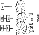
FIGURE 1 illustrates an example system capable of supporting at least some embodiments of the present invention. InFIG. 1 is illustrated mobile 110, which may comprise, for example, a cellular telephone, a tablet computer, a personal digital assistant, PDA, a laptop computer, a wireless data module, an automated wireless sensor or another kind of electronic device with a cellular connectivity capability. Also illustrated are cells labeled withreference numerals cells cells 5, 6 and 7, and finally location area LA3 comprisescells - At least some of base
stations controlling cells stations controlling cells - As a schematic reference,
FIG. 1 illustrates location area LA1 as comprising cells operating in accordange with the GSM radio access technology, such that basestations controlling cells BSC 120, which in turn is operably connected to a core network node, such as for example a mobileswitching centre MSC 140. LikewiseFIG. 1 illustrates location area LA2 as comprising cells operating in accordance with the WCDMA radio access technology, such that basestations controlling cells 5, 6 and 7 are operably connected toRNC 130, which in turn is operably connected to a core network node, which may be a mobile switching centre MSC or a serving general packet radio service support node, SGSN, 150. A location area may be known as a routing area in terminology of the WCDMA radio access technology. LikewiseFIG. 1 illustrates location area LA3 as comprising cells operating in accordance with the LTE radio access technology, such that basestations controlling cells -
FIG. 1 further illustrates two handovers, 100A and 100B. Inhandover 100A, mobile 110 is handed over from cell 1 tocell 4, which are both comprised in location area LA1. Since cell 1 andcell 4 are both comprised in the same location area, there is no need to update a database storing an association between an identity of mobile 110, or an identity of a subscription associated with mobile 110, and the location area where mobile 110 is reachable. The association may be referred to as a registration, thus when the database stores an association between mobile 110, or a corresponding subscription identity, and location area LA1, it may be said that mobile 110 is registered in location area LA1.Handover 100A may be referred to as an intra-location area handover.Handover 100B involves a change in attachment of mobile 110 fromcell 4 tocell 7. Sincecell 4 is comprised in location area LA1 andcell 7 is comprised in location area LA2,handover 100B may be referred to as an inter-location area handover. Updating of the database becomes necessary since mobile 110 is, afterhandover 100B, reachable in location area LA2, and no longer location area LA1. In some embodiments, a mobile may be registered simultaneously in a plurality of location areas. In these embodiments, updating the association becomes necessary when the mobile changes attachment to a cell that is comprised in a location area that isn't comprised in the plurality of location areas in which the mobile is registered. - When mobile 110 determines that it has handed over to a location area where mobile 110 isn't registered, mobile 110 may be configured to initiate, by sending a signal, a location area updating procedure toward the network to cause the association in the database to be updated with the new location area. A signal from mobile 110 initiating a location area update procedure is known in the GSM radio access technology, RAT, as a location area update request. In the WCDMA RAT the signal is known as a routing area update request. In the LTE RAT the signal is known as a tracking area update request.
- Following handover, mobile 110 may have an active context toward the network. This context may be known as a UE context. A context may be active between mobile 110 and a serving gateway, SGW, in an LTE core network, for example. A context may comprise at least one of parameters of internet protocol, IP, level bearers, network internal routing information and other information. In handover, the context may be transferred from the source base station to the target base station to enable seamless connectivity for mobile 110.
-
Mobile 110 may have a radio resource control, RRC, connection with a base station. When mobile 110 has a RRC connection, it may be considered to be in a RRC connected mode and capable of transferring information with the network. When mobile 110 is not in RRC connected mode, it may be in a RRC idle mode, for example. For example, when a user of mobile 110 triggers an application such as a web browser in mobile 110, mobile 110 may initiate a state transition from RRC idle to the RRC connected mode, to allow for the application to receive information from the network for presentation to the user. - In some cases, a location area update process, such as for example a location area update process, a routing area update process or a tracking area update process, cannot be completed successfully. For example, where mobile 110 transmits a signal initiating a location area update process, the signal comprising an identity of mobile 110 that the network doesn't recognize, the association between identity and location area cannot be updated in the database. Likewise where the network has implicitly detached mobile 110 from the network, there may be no current registration of mobile 110 in the database and thus an error condition may be generated.
Mobile 110 may become implicitly detached from the network when mobile 110 fails to perform a location area update procedure at a configured interval, for example. This may occur where mobile 110 has exhausted its battery, for example, or has been out of communication with the network for a time period that exceeds the configured interval. A third example is a case where the network has no evolved packet system, EPS, bearer context for mobile 110, which may cause a location area update request from mobile 110 to be rejected. - When a location area update procedure fails, the network may be configured to return, responsive to a location area update request message from mobile 110, a location area update reject message to mobile 110. In an LTE system, for example, the location area update reject message takes the form of a tracking area update reject.
- Two problems may arise in interactions between mobile 110 and a network in connection with rejected location area updating procedures. The first problem is illustrated in
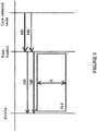
FIGURE 3 . A network rejecting a location area updating procedure may, in a location area update reject message, explicitly or implicitly request mobile 110 to re-attach to the network. Re-attaching to the network may comprise sending a new attachment request to the network.FIG. 3 illustrates at the top mobile, such as for example mobile 110, a base station controlling a cell into which the mobile has handed over into, and a core network node operably connected to the base station. At the start of the signaling illustrated inFIG. 3 , the mobile may have just recently handed over into a cell controlled by the base station, and responsive to the handover the mobile may have transmitted a location area update request message. Inphase 310, the core network node instructs the base station that the location area update request previously sent by the mobile is to be rejected. Responsively, the base station may be configured to inform the mobile of the rejection of the location area update process, which is illustrated asphase 320. The message ofphase 320 may request the mobile, implicitly or explicitly to re-attach to the network. The mobile ofFIG. 3 may be configured to always perform a re-attach requested in a location area update reject message with an existing RRC connection. Inphase 330, the core network node may transmit to the base station a context release instruction, for example a UE context release instruction message. Responsive to the message ofphase 330, the base station may be configured to transmit to the mobile a RRC connection release instruction message. - In some implementations, responsive to receiving a RRC connection release instruction message, the mobile is configured to begin release of an existing RRC connection, which may take an amount of time indicated in
FIG. 3 with Δ, during a teardown procedure indicated as 3XX. As teardown of an RRC connection is ongoing, the mobile may wind up in an error condition if it attempts to comply withmessage 320 by initiating attach over the RRC connection while teardown of the RRC connection is ongoing, that is if the mobile is in state 3XX. Recovery from the error condition may take as long as ten seconds, resulting in a significant degradation of perceived connection quality for a user of the mobile. The mobile could recover connectivity much sooner by waiting until time interval Δ has elapsed, the old RRC connection has been torn down, and then initiating re-attachment with a new RRC connection. - A second problem is illustrated in
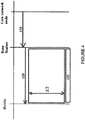
FIG. 4. FIG. 4 illustrates the mobile, base station and core network node likeFIG.3 , and likeFIG.3 , the mobile has just requested a location area update procedure, possibly responsive to handing over into a cell controlled by the base station. Inphase 410, the core network node informs the base station that the requested location area update procedure is rejected. Responsively, the base station informs the mobile that the location update procedure has been rejected by the network,phase 420. The message ofphase 420 may request re-attachment to the network. The mobile ofFIG. 4 may be configured to always perform a re-attach requested in a location area update reject message with a new RRC connection. Responsive to the message ofphase 420, the mobile may be configured to re-attach using a new RRC connection. In case the mobile however has an existing RRC connection, it may need to wait until the existing connection expires due to inactivity, the inactivity period being illustrated by period Δ2. This may be so, for example, where the radio access technology used does not comprise procedures enabling a mobile to request teardown of an existing RRC connection. In practical implementations, Δ2 may be of the order of 10 seconds. Following expiry of the inactivity time of the existing RRC connection, the existing RRC connection is caused to be torn down,phase 430, subsequent to which the mobile may re-attach using a new connection. As can be seen, similarly to the first problem, a delay of around ten seconds may be incurred. - A mobile 110 operating in accordance with at least some embodiments of the invention may be configured to avoid both aforementioned problems by determining, if the network will issue a radio resource connection release message, such as for example the message of
phase 340. To this end, responsive to receiving the location area update reject message ofphases phase 340, will be issued by the network. In detail, where a radio resource connection release message is issued, the mobile may be configured to responsively tear down an existing radio resource connection, wait until the teardown is complete, and then initiate re-attachment using a new radio resource connection, such as for example a RRC connection. Where the radio resource connection release message is not issued, the mobile may be configured to responsively use an already existing radio resource connection to initiate re-attachment. Acting in this way, the mobile will be able to avoid both the delay caused by the first problem, and the delay caused by the second problem. In other words, instead of always using either a new radio resource connection or an existing radio resource connection, a mobile may be configured to decide based on the determination, whether to use a new or existing radio resource connection to avoid both problems described above. A RRC connection is an example of a radio resource connection in accordance with the LTE and WCDMA radio access technologies. A failed location area update provedure may occur, for example, where a mobile changes attachment from a second- or third-generation radio access technology, such as GSM or WCDMA, to a fourth-generation radio access technology, such as LTE. - In general there is provided an apparatus, such as for example a mobile terminal or a control device for inclusion in a mobile terminal, to control the functioning of the mobile terminal. Examples of such control devices include a processor and a chipset. The apparatus may comprise a receiver configured to receive a location update reject message, such as for example a location area update reject message. Where the apparatus is a mobile terminal, the receiver may be a radio receiver comprised in the mobile terminal. Where the apparatus is a control device, the receiver may be an input device comprised in the control device, such as for example a serial port pin and associated serial port, or a parallel port, to enable the control device to receive information from, for example, a radio receiver comprised in a mobile terminal. The information may be conveyable from the radio receiver to the input device of the control device via electrical leads internal to a mobile terminal, for example.
- The apparatus may further comprise at least one processing core configured to determine whether a radio resource connection release message is issued in connection with the location update reject message. Responsive to determination that a radio resource connection release message is issued in connection with the location update reject message, the at least one processing core may be configured to initiate an attach procedure using a new radio resource connection. Responsive to a determination that no radio resource connection release message is issued in connection with the location update reject message, the at least one processing core may be configured to initiate an attach procedure using an existing radio resource connection.
- Initiating an attach procedure using an existing radio resource connection, such as for example a RRC connection, may comprise causing an attach request message to be transmitted to a base station on the existing radio resource connection. Initiating an attach procedure using a new radio resource connection, such as for example a RRC connection, may comprise causing a new radio resource connection request to be transmitted to a base station after an existing radio resource connection is torn down, and subsequent to the new radio resource connection being established, causing an attach request message to be transmitted to a base station on the new radio resource connection. Where no existing radio resource connection exists, initiating an attach procedure using a new radio resource connection may comprise causing a new radio resource connection request to be transmitted to a base station without tearing down an existing radio resource connection.
- In some embodiments, determining whether a radio resource connection release message is issued in connection with the location update reject message comprises the at least one processing core causing the apparatus to wait, following receipt of the location update reject message, for a preconfigured time period, for the radio resource connection release message to be received by the receiver. The waiting may be controlled by a timer set to the preconfigured time period, the timer being triggered by the receipt of the location update reject message. In these embodiments, waiting ends responsive to the timer expiring after the preconfigured time has elapsed since receipt of the location update reject message.
- In some embodiments, determining whether a radio resource connection release message is issued in connection with the location update reject message comprises checking whether the location update reject message comprises a radio resource connection release message.
- In some embodiments, the location update reject message is a location area update reject message, such as for example a tracking area update reject message or a routing area update reject message. A tracking area update reject message may be issued by an LTE base station, which is known as an eNB.
- In some embodiments, a tracking area update reject message comprises an implicit or explicit request for the apparatus to re-attach to the network transmitting the tracking area update reject message. A tracking area update reject message may comprise an indication as to a cause why the tracking area update procedure is rejected. The indication as to cause may comprise an indication as to at least one of the following causes: a user equipment identity cannot be determined by the network, a mobile has become implicitly detached and no EPS bearer context activated.
- In some embodiments, the apparatus is configured to select the length of the preconfigured time period based at least in part on a signaling message from the network. In some embodiments, the length of the preconfigured time period is selected in the apparatus in dependence of the radio access technology the location update reject message is in accordance with. The apparatus may receive from the network separate preconfigured time period lengths for a plurality of different radio access technologies, or different versions of the same radio access technology.
- In some embodiments, the preconfigured time period is 100 to 300 milliseconds long. In other embodiments, the preconfigured time period is 50 to 60 milliseconds long.
-
FIGURE 5 is a flowgraph illustrating a method in accordance with at least some embodiments of the invention. Inphase 510, a location update reject message is received. The location update reject message may comprise, for example, a routing area update reject message or a tracking area update reject message in accordance with WCDMA or LTE radio access technologies. - In
phase 520, it is determined whether a radio resource connection release message, such as for example a RRC connection release message, is issued in connection with the location update reject message. Responsive to a determination that a radio resource connection release message is issued in connection with the location update reject message, processing advances to phase 530 where an attach procedure is initiated, or caused to be initiated, using a new radio resource connection. Responsive to a determination that no radio resource connection release message is issued in connection with the location update reject message, processing advances fromphase 520 tophase 530, where an attach procedure is initiated, or caused to be initiated, using an existing radio resource connection. -
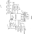
FIGURE 2 illustrates a block diagram of anapparatus 10 such as, for example, a mobile terminal, in accordance with at least some embodiments of the invention. While several features of the apparatus are illustrated and will be hereinafter described for purposes of example, other types of electronic devices, such as mobile telephones, mobile computers, portable digital assistants, PDAs, pagers, laptop computers, desktop computers, gaming devices, televisions, routers, home gateways, and other types of electronic systems, may employ various embodiments of the invention. - As shown, the
mobile terminal 10 may include at least oneantenna 12 in communication with atransmitter 14 and areceiver 16. Alternatively transmit and receive antennas may be separate. Themobile terminal 10 may also include aprocessor 20 configured to provide signals to and receive signals from the transmitter and receiver, respectively, and to control the functioning of the apparatus.Processor 20 may be configured to control the functioning of the transmitter and receiver by effecting control signaling via electrical leads to the transmitter and receiver. Likewiseprocessor 20 may be configured to control other elements ofapparatus 10 by effecting control signaling via electricalleads connecting processor 20 to the other elements, such as for example a display or a memory. Theprocessor 20 may, for example, be embodied as various means including circuitry, at least one processing core, one or more microprocessors with accompanying digital signal processor(s), one or more processor(s) without an accompanying digital signal processor, one or more coprocessors, one or more multi-core processors, one or more controllers, processing circuitry, one or more computers, various other processing elements including integrated circuits such as, for example, an application specific integrated circuit, ASIC, or field programmable gate array, FPGA, or some combination thereof. Accordingly, although illustrated inFIG. 2 as a single processor, in some embodiments theprocessor 20 comprises a plurality of processors or processing cores. Signals sent and received by theprocessor 20 may include signaling information in accordance with an air interface standard of an applicable cellular system, and/or any number of different wireline or wireless networking techniques, comprising but not limited to Wi-Fi, wireless local access network, WLAN, techniques such as Institute of Electrical and Electronics Engineers, IEEE, 802.11, 802.16, and/or the like. In addition, these signals may include speech data, user generated data, user requested data, and/or the like. In this regard, the apparatus may be capable of operating with one or more air interface standards, communication protocols, modulation types, access types, and/or the like. More particularly, the apparatus may be capable of operating in accordance with various first generation, 1G, second generation, 2G, 2.5G, third-generation, 3G, communication protocols, fourth-generation, 4G, communication protocols, Internet Protocol Multimedia Subsystem, IMS, communication protocols, for example, session initiation protocol, SIP, and/or the like. For example, the apparatus may be capable of operating in accordance with 2G wireless communication protocols IS-136, Time Division Multiple Access TDMA, Global System for Mobile communications, GSM, IS-95, Code Division Multiple Access, CDMA, and/or the like. Also, for example, the mobile terminal may be capable of operating in accordance with 2.5G wireless communication protocols General Packet Radio Service. GPRS, Enhanced Data GSM Environment, EDGE, and/or the like. Further, for example, the apparatus may be capable of operating in accordance with 3G wireless communication protocols such as Universal Mobile Telecommunications System, UMTS, Code Division Multiple Access 2000, CDMA2000, Wideband Code Division Multiple Access, WCDMA, Time Division-Synchronous Code Division Multiple Access, TD-SCDMA, and/or the like. The apparatus may be additionally capable of operating in accordance with 3.9G wireless communication protocols such as Long Term Evolution, LTE, or Evolved Universal Terrestrial Radio Access Network, E-UTRAN, and/or the like. Additionally, for example, the apparatus may be capable of operating in accordance with fourth-generation, 4G, wireless communication protocols such as LTE Advanced and/or the like as well as similar wireless communication protocols that may be developed in the future. - Some Narrow-band Advanced Mobile Phone System, NAMPS, as well as Total Access Communication System, TACS, mobile terminal apparatuses may also benefit from embodiments of this invention, as should dual or higher mode phone apparatuses, for example, digital/analog or TDMA/CDMA/analog phones. Additionally,
apparatus 10 may be capable of operating according to Wi-Fi or Worldwide Interoperability for Microwave Access, WiMAX, protocols. - It is understood that the
processor 20 may comprise circuitry for implementing audio/video and logic functions ofapparatus 10. For example, theprocessor 20 may comprise a digital signal processor device, a microprocessor device, an analog-to-digital converter, a digital-to-analog converter, and/or the like. Control and signal processing functions of the mobile terminal may be allocated between these devices according to their respective capabilities. The processor may additionally comprise an internal voice coder, VC, 20a, an internal data modem, DM, 20b, and/or the like. Further, the processor may comprise functionality to operate one or more software programs, which may be stored in memory. In general,processor 20 and stored software instructions may be configured to causeapparatus 10 to perform actions. For example,processor 20 may be capable of operating a connectivity program, such as a web browser. The connectivity program may allow themobile terminal 10 to transmit and receive web content, such as location-based content, according to a protocol, such as wireless application protocol, WAP, hypertext transfer protocol, HTTP, and/or the like -
Apparatus 10 may also comprise a user interface including, for example, an earphone orspeaker 24, aringer 22, amicrophone 26, adisplay 28, a user input interface, and/or the like, which may be operationally coupled to theprocessor 20. In this regard, theprocessor 20 may comprise user interface circuitry configured to control at least some functions of one or more elements of the user interface, such as, for example, thespeaker 24, theringer 22, themicrophone 26, thedisplay 28, and/or the like. Theprocessor 20 and/or user interface circuitry comprising theprocessor 20 may be configured to control one or more functions of one or more elements of the user interface through computer program instructions, for example, software and/or firmware, stored on a memory accessible to theprocessor 20, for example,volatile memory 40,non-volatile memory 42, and/or the like. Although not shown, the apparatus may comprise a battery for powering various circuits related to the mobile terminal, for example, a circuit to provide mechanical vibration as a detectable output. The user input interface may comprise devices allowing the apparatus to receive data, such as akeypad 30, a touch display, which is not shown, a joystick, which is not shown, and/or at least one other input device. In embodiments including a keypad, the keypad may comprise numeric 0-9 and related keys, and/or other keys for operating the apparatus. - As shown in
FIG. 2 ,apparatus 10 may also include one or more means for sharing and/or obtaining data. For example, the apparatus may comprise a short-range radio frequency, RF, transceiver and/orinterrogator 64 so data may be shared with and/or obtained from electronic devices in accordance with RF techniques. The apparatus may comprise other short-range transceivers, such as, for example, an infrared, IR,transceiver 66, a Bluetooth™, BT,transceiver 68 operating using Bluetooth™ brand wireless technology developed by the Bluetooth™ Special Interest Group, a wireless universal serial bus, USB,transceiver 70 and/or the like. TheBluetooth™ transceiver 68 may be capable of operating according to low power or ultra-low power Bluetooth™ technology, for example, Wibree™, radio standards. In this regard, theapparatus 10 and, in particular, the short-range transceiver may be capable of transmitting data to and/or receiving data from electronic devices within a proximity of the apparatus, such as within 10 meters, for example. Although not shown, the apparatus may be capable of transmitting and/or receiving data from electronic devices according to various wireless networking techniques, including 6LoWpan, Wi-Fi, Wi-Fi low power, WLAN techniques such as IEEE 802.11 techniques, IEEE 802.15 techniques, IEEE 802.16 techniques, and/or the like. - The
apparatus 10 may comprise memory, such as a subscriber identity module, SIM, 38, a removable user identity module, R-UIM, and/or the like, which may store information elements related to a mobile subscriber. In addition to the SIM, the apparatus may comprise other removable and/or fixed memory. Theapparatus 10 may includevolatile memory 40 and/ornon-volatile memory 42. For example,volatile memory 40 may include Random Access Memory, RAM, including dynamic and/or static RAM, on-chip or off-chip cache memory, and/or the like.Non-volatile memory 42, which may be embedded and/or removable, may include, for example, read-only memory, flash memory, magnetic storage devices, for example, hard disks, floppy disk drives, magnetic tape, etc., optical disc drives and/or media, non-volatile random access memory, NVRAM, and/or the like. Likevolatile memory 40non-volatile memory 42 may include a cache area for temporary storage of data. At least part of the volatile and/or non-volatile memory may be embedded inprocessor 20. The memories may store one or more software programs, instructions, pieces of information, data, and/or the like which may be used by the apparatus for performing functions of the mobile terminal. For example, the memories may comprise an identifier, such as an international mobile equipment identification, IMEI, code, capable of uniquely identifyingapparatus 10. - Without in any way limiting the scope, interpretation, or application of the claims appearing below, a technical effect of one or more of the example embodiments disclosed herein is that delays are avoided in error situations in connection with location area update rejection situations.
- Embodiments of the present invention may be implemented in software, hardware, application logic or a combination of software, hardware and application logic. The software, application logic and/or hardware may reside on
memory 40 and/or 42 ofFIG. 2 , theprocessor 20 or electronic components, for example. In an example embodiment, the application logic, software or an instruction set is maintained on any one of various conventional computer-readable media. In the context of this document, a "computer-readable medium" may be any media or means that can contain, store, communicate, propagate or transport the instructions for use by or in connection with an instruction execution system, apparatus, or device, such as a computer, with one example of a computer described and depicted inFIGURE 2 . A computer-readable medium may comprise a computer-readable non-transitory storage medium that may be any media or means that can contain or store the instructions for use by or in connection with an instruction execution system, apparatus, or device, such as a computer. The scope of the invention comprises computer programs configured to cause methods according to embodiments of the invention to be performed. - If desired, the different functions discussed herein may be performed in a different order and/or concurrently with each other. Furthermore, if desired, one or more of the above-described functions may be optional or may be combined.
- Although various aspects of the invention are set out in the independent claims, other aspects of the invention comprise other combinations of features from the described embodiments and/or the dependent claims with the features of the independent claims, and not solely the combinations explicitly set out in the claims.
- It is also noted herein that while the above describes example embodiments of the invention, these descriptions should not be viewed in a limiting sense. Rather, there are several variations and modifications which may be made without departing from the scope of the present invention as defined in the appended claims.
Claims (15)
- A mobile apparatus (10, 20), comprising:means for receiving (16, 20) a location update reject message, characterized bymeans for determining (20) whether a radio resource connection release message is issued in connection with the location update reject message, andmeans for, responsive to a determination that the radio resource connection release message is issued in connection with the location update reject message, initiating an attach procedure using a new radio resource connection, and responsive to a determination that no radio resource connection release message is issued in connection with the location update reject message, initiating an attach procedure using an existing radio resource connection (20).
- A mobile apparatus (10, 20) according to claim 1, wherein the means for determining (20) are configured to determine whether a radio resource connection release message is issued in connection with the location update reject message by waiting, following receipt of the location update reject message, for a preconfigured time period, for the radio resource connection release message.
- A mobile apparatus (10, 20) according to claim 1 or 2, wherein the location update reject message comprises a tracking area update reject message according to long term evolution technology.
- A mobile apparatus (10, 20) according to claim 3, wherein the tracking area update reject message requests a new attach procedure.
- A mobile apparatus (10, 20) according to claim 3 or 4, wherein the tracking area update reject message comprises at least one of the following cause indications: user equipment identity cannot be determined by the network, implicitly detached and no EPS bearer context activated.
- A mobile apparatus (10, 20) according to any of claims 2 - 5, wherein the mobile apparatus (10, 20) is configured to at least one of receive information defining a length of the preconfigured time period from a network node and select the length of the preconfigured time period in dependence of a radio access technology the location update reject message is in accordance with.
- A mobile apparatus (10, 20) according to any of claims 2 - 6, wherein the preconfigured time period is 100 to 300 milliseconds long.
- A mobile apparatus (10, 20) according to any preceding claim, wherein the mobile apparatus (10, 20) comprises a mobile communication device (10), the apparatus further comprising an antenna (12) coupled to the means for receiving (16, 20) and configured to provide signals to the means for determining (20).
- A method performed by a mobile apparatus, comprising:receiving (510) a location update reject message, characterized bydetermining (520) whether a radio resource connection release message is issued in connection with the location update reject message, andresponsive to a determination that the radio resource connection release message is issued in connection with the location update reject message, initiating an attach procedure using a new radio resource connection (530), and responsive to a determination that no radio resource connection release message is issued in connection with the location update reject message, initiating an attach procedure using an existing radio resource connection (540).
- A method according to claim 9, wherein the determining (520) comprises waiting, following receipt of the location update reject message, for a preconfigured time period, for the radio resource connection release message.
- A method according to claim 9 or 10, wherein the location update reject message comprises a tracking area update reject message according to long term evolution technology.
- A method according to claim 11, wherein the tracking area update reject message requests a new attach procedure.
- A method according to claim 11 or 12, wherein the tracking area update reject message comprises at least one of the following cause indications: user equipment identity cannot be determined by the network, implicitly detached and no EPS bearer context activated.
- A method according to any of claims 10 - 13, further comprising at least one of receiving information defining a length of the preconfigured time period from a network node and selecting the length of the preconfigured time period in dependence of a radio access technology the location update reject message is in accordance with.
- A computer program comprising instructions, which, when the program is executed by a mobile apparatus, cause the mobile apparatus to perform the method according to at least one of claims 9 - 14.
Applications Claiming Priority (1)
| Application Number | Priority Date | Filing Date | Title |
|---|---|---|---|
| PCT/FI2012/050633 WO2013190170A1 (en) | 2012-06-19 | 2012-06-19 | Method and apparatus for management of cellular connections |
Publications (3)
| Publication Number | Publication Date |
|---|---|
| EP2862408A1 EP2862408A1 (en) | 2015-04-22 |
| EP2862408A4 EP2862408A4 (en) | 2016-03-02 |
| EP2862408B1 true EP2862408B1 (en) | 2019-07-24 |
Family
ID=49768172
Family Applications (1)
| Application Number | Title | Priority Date | Filing Date |
|---|---|---|---|
| EP12879539.0A Active EP2862408B1 (en) | 2012-06-19 | 2012-06-19 | Method and apparatus for management of cellular connections |
Country Status (8)
| Country | Link |
|---|---|
| US (1) | US9578677B2 (en) |
| EP (1) | EP2862408B1 (en) |
| JP (1) | JP5887466B2 (en) |
| CN (1) | CN104396336B (en) |
| HK (1) | HK1206899A1 (en) |
| IN (1) | IN2015DN00087A (en) |
| TW (1) | TWI554127B (en) |
| WO (1) | WO2013190170A1 (en) |
Families Citing this family (7)
| Publication number | Priority date | Publication date | Assignee | Title |
|---|---|---|---|---|
| CN103747492A (en) * | 2014-01-08 | 2014-04-23 | 华为终端有限公司 | Method for accessing terminal into long-term evolution network and terminal |
| CN105451325A (en) * | 2014-09-24 | 2016-03-30 | 中兴通讯股份有限公司 | Processing method and device for abnormal card no-loading in LTE network |
| US10341923B2 (en) * | 2016-01-29 | 2019-07-02 | Google Llc | Techniques for minimizing user disruption during network connection switching |
| CN107635270B (en) * | 2016-07-13 | 2021-03-05 | 三星电子株式会社 | Method for processing attach reject message with #14 cause at user equipment |
| CN110622564B (en) * | 2016-12-21 | 2021-10-01 | 鸿颖创新有限公司 | State transition method of wireless communication system |
| MX2020011703A (en) * | 2018-05-07 | 2020-12-10 | Ericsson Telefon Ab L M | Methods and apparatuses for handling radio access network notification area (rna) update configuration upon reject. |
| CN109495916B (en) * | 2018-11-20 | 2022-05-10 | 华为技术服务有限公司 | Communication method and device |
Family Cites Families (20)
| Publication number | Priority date | Publication date | Assignee | Title |
|---|---|---|---|---|
| DE69634560T2 (en) * | 1996-05-03 | 2006-02-16 | Agilent Technologies Inc., A Delaware Corp., Palo Alto | Tracking and passing on in a mobile radio system by monitoring signaling messages |
| DE69728079T2 (en) * | 1996-05-03 | 2005-01-20 | Agilent Technologies, Inc. (n.d.Ges.d.Staates Delaware), Palo Alto | Method and device for tracking the change of the identification code in a mobile communication system |
| US6314290B1 (en) * | 1998-07-13 | 2001-11-06 | Hughes Electronics Corporation | Mobile satellite system and method for implementing a single-hop terminal-to-terminal call |
| US6937861B2 (en) * | 2001-02-13 | 2005-08-30 | Telefonaktiebolaget Lm Ericsson (Publ) | Connection management for dual mode access terminals in a radio network |
| DE10233606A1 (en) * | 2002-07-24 | 2004-02-12 | Siemens Ag | WLAN to UMTS terminal connection procedure uses a Universal Chip Card to monitor activity and exchange set up data |
| US7272397B2 (en) * | 2003-10-17 | 2007-09-18 | Kineto Wireless, Inc. | Service access control interface for an unlicensed wireless communication system |
| US20060094423A1 (en) * | 2004-10-29 | 2006-05-04 | Alok Sharma | Method and apparatus for providing managed roaming service in a wireless network |
| GB0619179D0 (en) * | 2006-09-29 | 2006-11-08 | Ip Access Ltd | Telecommunications access control system and method |
| SI2082605T1 (en) * | 2006-10-05 | 2018-02-28 | Eureka S.A. | Systems and methods for automated wireless authorization for entry into a geographic area |
| KR20090069472A (en) * | 2007-12-26 | 2009-07-01 | 삼성전자주식회사 | Apparatus and method for location updating of a portable terminal in a radio network |
| US8538425B2 (en) * | 2008-07-01 | 2013-09-17 | Qualcomm Incorporated | Apparatus and method for improving mobile terminated cell setup performance during inter-frequency cell reselection |
| US8229397B2 (en) * | 2008-09-23 | 2012-07-24 | Airvana, Corp. | Access terminal authorization at private access points in wireless networks |
| US8971884B2 (en) * | 2008-09-30 | 2015-03-03 | At&T Mobility Ii Llc | Rejection notification to a universal integrated circuit card |
| GB2466452A (en) | 2008-12-18 | 2010-06-23 | Ubiquisys Ltd | A base station, for a cellular communication network |
| US8798623B2 (en) * | 2009-08-14 | 2014-08-05 | General Motors Llc | Network selection and base station acquisition with OTA programming for a vehicle telematics unit |
| WO2012010217A1 (en) * | 2010-07-23 | 2012-01-26 | Nokia Siemens Networks Oy | Method, system, apparatus and related computer programs for selecting a wireless network |
| KR101491579B1 (en) * | 2010-09-28 | 2015-02-09 | 블랙베리 리미티드 | Releasing connections with local gw when ue moves out of residential/enterprise network coverage |
| EP2666314B1 (en) * | 2011-01-21 | 2019-05-15 | BlackBerry Limited | Network apparatus and process to determine the connection context for connections used for (local) offloading |
| US9066312B2 (en) * | 2011-03-03 | 2015-06-23 | Acer Incorporated | Mobile communication devices and location registration methods |
| US9578554B2 (en) * | 2011-09-21 | 2017-02-21 | Qualcomm Incorporated | Methods and apparatus for improving a call fallback user experience |
-
2012
- 2012-06-19 CN CN201280074053.7A patent/CN104396336B/en active Active
- 2012-06-19 US US14/408,581 patent/US9578677B2/en active Active
- 2012-06-19 IN IN87DEN2015 patent/IN2015DN00087A/en unknown
- 2012-06-19 WO PCT/FI2012/050633 patent/WO2013190170A1/en active Application Filing
- 2012-06-19 JP JP2015516655A patent/JP5887466B2/en active Active
- 2012-06-19 EP EP12879539.0A patent/EP2862408B1/en active Active
-
2013
- 2013-06-18 TW TW102121515A patent/TWI554127B/en active
-
2015
- 2015-07-27 HK HK15107159.5A patent/HK1206899A1/en unknown
Non-Patent Citations (1)
| Title |
|---|
| None * |
Also Published As
| Publication number | Publication date |
|---|---|
| EP2862408A4 (en) | 2016-03-02 |
| US20150156813A1 (en) | 2015-06-04 |
| IN2015DN00087A (en) | 2015-05-29 |
| JP5887466B2 (en) | 2016-03-16 |
| HK1206899A1 (en) | 2016-01-15 |
| CN104396336A (en) | 2015-03-04 |
| US9578677B2 (en) | 2017-02-21 |
| TWI554127B (en) | 2016-10-11 |
| TW201404201A (en) | 2014-01-16 |
| WO2013190170A1 (en) | 2013-12-27 |
| JP2015523800A (en) | 2015-08-13 |
| CN104396336B (en) | 2018-05-01 |
| EP2862408A1 (en) | 2015-04-22 |
Similar Documents
| Publication | Publication Date | Title |
|---|---|---|
| EP2862408B1 (en) | Method and apparatus for management of cellular connections | |
| KR102386530B1 (en) | Method and apparatus for transmitting a handover report and an rlf report | |
| US9131476B2 (en) | Optimizing voice calls on packet switched networks | |
| US9232452B2 (en) | Method of handling an inter rat handover in wireless communication system and related communication device | |
| US9923735B2 (en) | Systems, methods, and apparatuses for handling a legacy circuit switched communication | |
| US9801098B2 (en) | Handover method, communication device and communication system | |
| US20110310844A1 (en) | Method, apparatus and computer program product for transfer of cabability support information in a multi-rat environment | |
| US11758442B2 (en) | Information processing method and device | |
| US11368905B2 (en) | Device and method of handling a connection in a wireless communication system | |
| WO2010078783A1 (en) | Method, device and system for processing circuit switching domain service | |
| EP2858414B1 (en) | Method and apparatus for implementing voice service fallback | |
| US20230262545A1 (en) | Link recovery via cells prepared with information for handovers including cho and daps | |
| WO2017063402A1 (en) | Base station, mobility management entity, off-loading method and system | |
| CN115777233A (en) | Managing communications in the event of a master cell group failure | |
| WO2019140560A1 (en) | Handover method and device, and computer storage medium | |
| WO2024041422A1 (en) | Communication method and apparatus, and terminal and core network node |
Legal Events
| Date | Code | Title | Description |
|---|---|---|---|
| PUAI | Public reference made under article 153(3) epc to a published international application that has entered the european phase |
Free format text: ORIGINAL CODE: 0009012 |
|
| 17P | Request for examination filed |
Effective date: 20141118 |
|
| AK | Designated contracting states |
Kind code of ref document: A1 Designated state(s): AL AT BE BG CH CY CZ DE DK EE ES FI FR GB GR HR HU IE IS IT LI LT LU LV MC MK MT NL NO PL PT RO RS SE SI SK SM TR |
|
| AX | Request for extension of the european patent |
Extension state: BA ME |
|
| RAP1 | Party data changed (applicant data changed or rights of an application transferred) |
Owner name: NOKIA TECHNOLOGIES OY |
|
| DAX | Request for extension of the european patent (deleted) | ||
| RA4 | Supplementary search report drawn up and despatched (corrected) |
Effective date: 20160203 |
|
| RIC1 | Information provided on ipc code assigned before grant |
Ipc: H04W 60/00 20090101ALI20160128BHEP Ipc: H04W 76/00 20090101AFI20160128BHEP Ipc: H04W 24/04 20090101ALI20160128BHEP |
|
| REG | Reference to a national code |
Ref country code: DE Ref legal event code: R079 Ref document number: 602012062363 Country of ref document: DE Free format text: PREVIOUS MAIN CLASS: H04W0076000000 Ipc: H04W0060000000 |
|
| GRAP | Despatch of communication of intention to grant a patent |
Free format text: ORIGINAL CODE: EPIDOSNIGR1 |
|
| STAA | Information on the status of an ep patent application or granted ep patent |
Free format text: STATUS: GRANT OF PATENT IS INTENDED |
|
| RIC1 | Information provided on ipc code assigned before grant |
Ipc: H04W 60/00 20090101AFI20190110BHEP Ipc: H04W 24/04 20090101ALN20190110BHEP Ipc: H04W 76/38 20180101ALI20190110BHEP |
|
| INTG | Intention to grant announced |
Effective date: 20190212 |
|
| GRAS | Grant fee paid |
Free format text: ORIGINAL CODE: EPIDOSNIGR3 |
|
| GRAA | (expected) grant |
Free format text: ORIGINAL CODE: 0009210 |
|
| STAA | Information on the status of an ep patent application or granted ep patent |
Free format text: STATUS: THE PATENT HAS BEEN GRANTED |
|
| AK | Designated contracting states |
Kind code of ref document: B1 Designated state(s): AL AT BE BG CH CY CZ DE DK EE ES FI FR GB GR HR HU IE IS IT LI LT LU LV MC MK MT NL NO PL PT RO RS SE SI SK SM TR |
|
| REG | Reference to a national code |
Ref country code: GB Ref legal event code: FG4D |
|
| REG | Reference to a national code |
Ref country code: CH Ref legal event code: EP |
|
| REG | Reference to a national code |
Ref country code: DE Ref legal event code: R096 Ref document number: 602012062363 Country of ref document: DE |
|
| REG | Reference to a national code |
Ref country code: AT Ref legal event code: REF Ref document number: 1159816 Country of ref document: AT Kind code of ref document: T Effective date: 20190815 |
|
| REG | Reference to a national code |
Ref country code: IE Ref legal event code: FG4D |
|
| RAP2 | Party data changed (patent owner data changed or rights of a patent transferred) |
Owner name: NOKIA TECHNOLOGIES OY |
|
| REG | Reference to a national code |
Ref country code: NL Ref legal event code: MP Effective date: 20190724 |
|
| REG | Reference to a national code |
Ref country code: LT Ref legal event code: MG4D |
|
| REG | Reference to a national code |
Ref country code: AT Ref legal event code: MK05 Ref document number: 1159816 Country of ref document: AT Kind code of ref document: T Effective date: 20190724 |
|
| PG25 | Lapsed in a contracting state [announced via postgrant information from national office to epo] |
Ref country code: SE Free format text: LAPSE BECAUSE OF FAILURE TO SUBMIT A TRANSLATION OF THE DESCRIPTION OR TO PAY THE FEE WITHIN THE PRESCRIBED TIME-LIMIT Effective date: 20190724 Ref country code: BG Free format text: LAPSE BECAUSE OF FAILURE TO SUBMIT A TRANSLATION OF THE DESCRIPTION OR TO PAY THE FEE WITHIN THE PRESCRIBED TIME-LIMIT Effective date: 20191024 Ref country code: NL Free format text: LAPSE BECAUSE OF FAILURE TO SUBMIT A TRANSLATION OF THE DESCRIPTION OR TO PAY THE FEE WITHIN THE PRESCRIBED TIME-LIMIT Effective date: 20190724 Ref country code: NO Free format text: LAPSE BECAUSE OF FAILURE TO SUBMIT A TRANSLATION OF THE DESCRIPTION OR TO PAY THE FEE WITHIN THE PRESCRIBED TIME-LIMIT Effective date: 20191024 Ref country code: HR Free format text: LAPSE BECAUSE OF FAILURE TO SUBMIT A TRANSLATION OF THE DESCRIPTION OR TO PAY THE FEE WITHIN THE PRESCRIBED TIME-LIMIT Effective date: 20190724 Ref country code: AT Free format text: LAPSE BECAUSE OF FAILURE TO SUBMIT A TRANSLATION OF THE DESCRIPTION OR TO PAY THE FEE WITHIN THE PRESCRIBED TIME-LIMIT Effective date: 20190724 Ref country code: PT Free format text: LAPSE BECAUSE OF FAILURE TO SUBMIT A TRANSLATION OF THE DESCRIPTION OR TO PAY THE FEE WITHIN THE PRESCRIBED TIME-LIMIT Effective date: 20191125 Ref country code: LT Free format text: LAPSE BECAUSE OF FAILURE TO SUBMIT A TRANSLATION OF THE DESCRIPTION OR TO PAY THE FEE WITHIN THE PRESCRIBED TIME-LIMIT Effective date: 20190724 Ref country code: FI Free format text: LAPSE BECAUSE OF FAILURE TO SUBMIT A TRANSLATION OF THE DESCRIPTION OR TO PAY THE FEE WITHIN THE PRESCRIBED TIME-LIMIT Effective date: 20190724 |
|
| PG25 | Lapsed in a contracting state [announced via postgrant information from national office to epo] |
Ref country code: GR Free format text: LAPSE BECAUSE OF FAILURE TO SUBMIT A TRANSLATION OF THE DESCRIPTION OR TO PAY THE FEE WITHIN THE PRESCRIBED TIME-LIMIT Effective date: 20191025 Ref country code: ES Free format text: LAPSE BECAUSE OF FAILURE TO SUBMIT A TRANSLATION OF THE DESCRIPTION OR TO PAY THE FEE WITHIN THE PRESCRIBED TIME-LIMIT Effective date: 20190724 Ref country code: RS Free format text: LAPSE BECAUSE OF FAILURE TO SUBMIT A TRANSLATION OF THE DESCRIPTION OR TO PAY THE FEE WITHIN THE PRESCRIBED TIME-LIMIT Effective date: 20190724 Ref country code: IS Free format text: LAPSE BECAUSE OF FAILURE TO SUBMIT A TRANSLATION OF THE DESCRIPTION OR TO PAY THE FEE WITHIN THE PRESCRIBED TIME-LIMIT Effective date: 20191124 Ref country code: AL Free format text: LAPSE BECAUSE OF FAILURE TO SUBMIT A TRANSLATION OF THE DESCRIPTION OR TO PAY THE FEE WITHIN THE PRESCRIBED TIME-LIMIT Effective date: 20190724 Ref country code: LV Free format text: LAPSE BECAUSE OF FAILURE TO SUBMIT A TRANSLATION OF THE DESCRIPTION OR TO PAY THE FEE WITHIN THE PRESCRIBED TIME-LIMIT Effective date: 20190724 |
|
| PG25 | Lapsed in a contracting state [announced via postgrant information from national office to epo] |
Ref country code: TR Free format text: LAPSE BECAUSE OF FAILURE TO SUBMIT A TRANSLATION OF THE DESCRIPTION OR TO PAY THE FEE WITHIN THE PRESCRIBED TIME-LIMIT Effective date: 20190724 |
|
| PG25 | Lapsed in a contracting state [announced via postgrant information from national office to epo] |
Ref country code: DK Free format text: LAPSE BECAUSE OF FAILURE TO SUBMIT A TRANSLATION OF THE DESCRIPTION OR TO PAY THE FEE WITHIN THE PRESCRIBED TIME-LIMIT Effective date: 20190724 Ref country code: RO Free format text: LAPSE BECAUSE OF FAILURE TO SUBMIT A TRANSLATION OF THE DESCRIPTION OR TO PAY THE FEE WITHIN THE PRESCRIBED TIME-LIMIT Effective date: 20190724 Ref country code: IT Free format text: LAPSE BECAUSE OF FAILURE TO SUBMIT A TRANSLATION OF THE DESCRIPTION OR TO PAY THE FEE WITHIN THE PRESCRIBED TIME-LIMIT Effective date: 20190724 Ref country code: EE Free format text: LAPSE BECAUSE OF FAILURE TO SUBMIT A TRANSLATION OF THE DESCRIPTION OR TO PAY THE FEE WITHIN THE PRESCRIBED TIME-LIMIT Effective date: 20190724 Ref country code: PL Free format text: LAPSE BECAUSE OF FAILURE TO SUBMIT A TRANSLATION OF THE DESCRIPTION OR TO PAY THE FEE WITHIN THE PRESCRIBED TIME-LIMIT Effective date: 20190724 |
|
| PG25 | Lapsed in a contracting state [announced via postgrant information from national office to epo] |
Ref country code: IS Free format text: LAPSE BECAUSE OF FAILURE TO SUBMIT A TRANSLATION OF THE DESCRIPTION OR TO PAY THE FEE WITHIN THE PRESCRIBED TIME-LIMIT Effective date: 20200224 Ref country code: SK Free format text: LAPSE BECAUSE OF FAILURE TO SUBMIT A TRANSLATION OF THE DESCRIPTION OR TO PAY THE FEE WITHIN THE PRESCRIBED TIME-LIMIT Effective date: 20190724 Ref country code: SM Free format text: LAPSE BECAUSE OF FAILURE TO SUBMIT A TRANSLATION OF THE DESCRIPTION OR TO PAY THE FEE WITHIN THE PRESCRIBED TIME-LIMIT Effective date: 20190724 Ref country code: CZ Free format text: LAPSE BECAUSE OF FAILURE TO SUBMIT A TRANSLATION OF THE DESCRIPTION OR TO PAY THE FEE WITHIN THE PRESCRIBED TIME-LIMIT Effective date: 20190724 |
|
| REG | Reference to a national code |
Ref country code: DE Ref legal event code: R097 Ref document number: 602012062363 Country of ref document: DE |
|
| PLBE | No opposition filed within time limit |
Free format text: ORIGINAL CODE: 0009261 |
|
| STAA | Information on the status of an ep patent application or granted ep patent |
Free format text: STATUS: NO OPPOSITION FILED WITHIN TIME LIMIT |
|
| PG2D | Information on lapse in contracting state deleted |
Ref country code: IS |
|
| 26N | No opposition filed |
Effective date: 20200603 |
|
| PG25 | Lapsed in a contracting state [announced via postgrant information from national office to epo] |
Ref country code: SI Free format text: LAPSE BECAUSE OF FAILURE TO SUBMIT A TRANSLATION OF THE DESCRIPTION OR TO PAY THE FEE WITHIN THE PRESCRIBED TIME-LIMIT Effective date: 20190724 |
|
| PG25 | Lapsed in a contracting state [announced via postgrant information from national office to epo] |
Ref country code: MC Free format text: LAPSE BECAUSE OF FAILURE TO SUBMIT A TRANSLATION OF THE DESCRIPTION OR TO PAY THE FEE WITHIN THE PRESCRIBED TIME-LIMIT Effective date: 20190724 |
|
| REG | Reference to a national code |
Ref country code: CH Ref legal event code: PL |
|
| GBPC | Gb: european patent ceased through non-payment of renewal fee |
Effective date: 20200619 |
|
| PG25 | Lapsed in a contracting state [announced via postgrant information from national office to epo] |
Ref country code: LU Free format text: LAPSE BECAUSE OF NON-PAYMENT OF DUE FEES Effective date: 20200619 |
|
| REG | Reference to a national code |
Ref country code: BE Ref legal event code: MM Effective date: 20200630 |
|
| PG25 | Lapsed in a contracting state [announced via postgrant information from national office to epo] |
Ref country code: CH Free format text: LAPSE BECAUSE OF NON-PAYMENT OF DUE FEES Effective date: 20200630 Ref country code: IE Free format text: LAPSE BECAUSE OF NON-PAYMENT OF DUE FEES Effective date: 20200619 Ref country code: LI Free format text: LAPSE BECAUSE OF NON-PAYMENT OF DUE FEES Effective date: 20200630 Ref country code: GB Free format text: LAPSE BECAUSE OF NON-PAYMENT OF DUE FEES Effective date: 20200619 |
|
| PG25 | Lapsed in a contracting state [announced via postgrant information from national office to epo] |
Ref country code: BE Free format text: LAPSE BECAUSE OF NON-PAYMENT OF DUE FEES Effective date: 20200630 |
|
| PG25 | Lapsed in a contracting state [announced via postgrant information from national office to epo] |
Ref country code: MT Free format text: LAPSE BECAUSE OF FAILURE TO SUBMIT A TRANSLATION OF THE DESCRIPTION OR TO PAY THE FEE WITHIN THE PRESCRIBED TIME-LIMIT Effective date: 20190724 Ref country code: CY Free format text: LAPSE BECAUSE OF FAILURE TO SUBMIT A TRANSLATION OF THE DESCRIPTION OR TO PAY THE FEE WITHIN THE PRESCRIBED TIME-LIMIT Effective date: 20190724 |
|
| PG25 | Lapsed in a contracting state [announced via postgrant information from national office to epo] |
Ref country code: MK Free format text: LAPSE BECAUSE OF FAILURE TO SUBMIT A TRANSLATION OF THE DESCRIPTION OR TO PAY THE FEE WITHIN THE PRESCRIBED TIME-LIMIT Effective date: 20190724 |
|
| PGFP | Annual fee paid to national office [announced via postgrant information from national office to epo] |
Ref country code: FR Payment date: 20230510 Year of fee payment: 12 Ref country code: DE Payment date: 20230502 Year of fee payment: 12 |