EP2862270B1 - A method and control unit for an electric motor or generator - Google Patents
A method and control unit for an electric motor or generator Download PDFInfo
- Publication number
- EP2862270B1 EP2862270B1 EP13747502.6A EP13747502A EP2862270B1 EP 2862270 B1 EP2862270 B1 EP 2862270B1 EP 13747502 A EP13747502 A EP 13747502A EP 2862270 B1 EP2862270 B1 EP 2862270B1
- Authority
- EP
- European Patent Office
- Prior art keywords
- electric motor
- value
- sub
- motor
- parameter
- Prior art date
- Legal status (The legal status is an assumption and is not a legal conclusion. Google has not performed a legal analysis and makes no representation as to the accuracy of the status listed.)
- Active
Links
Images



Classifications
-
- H—ELECTRICITY
- H02—GENERATION; CONVERSION OR DISTRIBUTION OF ELECTRIC POWER
- H02P—CONTROL OR REGULATION OF ELECTRIC MOTORS, ELECTRIC GENERATORS OR DYNAMO-ELECTRIC CONVERTERS; CONTROLLING TRANSFORMERS, REACTORS OR CHOKE COILS
- H02P29/00—Arrangements for regulating or controlling electric motors, appropriate for both AC and DC motors
- H02P29/02—Providing protection against overload without automatic interruption of supply
- H02P29/032—Preventing damage to the motor, e.g. setting individual current limits for different drive conditions
-
- G—PHYSICS
- G01—MEASURING; TESTING
- G01R—MEASURING ELECTRIC VARIABLES; MEASURING MAGNETIC VARIABLES
- G01R31/00—Arrangements for testing electric properties; Arrangements for locating electric faults; Arrangements for electrical testing characterised by what is being tested not provided for elsewhere
- G01R31/34—Testing dynamo-electric machines
- G01R31/343—Testing dynamo-electric machines in operation
-
- H—ELECTRICITY
- H02—GENERATION; CONVERSION OR DISTRIBUTION OF ELECTRIC POWER
- H02P—CONTROL OR REGULATION OF ELECTRIC MOTORS, ELECTRIC GENERATORS OR DYNAMO-ELECTRIC CONVERTERS; CONTROLLING TRANSFORMERS, REACTORS OR CHOKE COILS
- H02P29/00—Arrangements for regulating or controlling electric motors, appropriate for both AC and DC motors
- H02P29/02—Providing protection against overload without automatic interruption of supply
- H02P29/024—Detecting a fault condition, e.g. short circuit, locked rotor, open circuit or loss of load
- H02P29/027—Detecting a fault condition, e.g. short circuit, locked rotor, open circuit or loss of load the fault being an over-current
-
- B—PERFORMING OPERATIONS; TRANSPORTING
- B60—VEHICLES IN GENERAL
- B60L—PROPULSION OF ELECTRICALLY-PROPELLED VEHICLES; SUPPLYING ELECTRIC POWER FOR AUXILIARY EQUIPMENT OF ELECTRICALLY-PROPELLED VEHICLES; ELECTRODYNAMIC BRAKE SYSTEMS FOR VEHICLES IN GENERAL; MAGNETIC SUSPENSION OR LEVITATION FOR VEHICLES; MONITORING OPERATING VARIABLES OF ELECTRICALLY-PROPELLED VEHICLES; ELECTRIC SAFETY DEVICES FOR ELECTRICALLY-PROPELLED VEHICLES
- B60L15/00—Methods, circuits, or devices for controlling the traction-motor speed of electrically-propelled vehicles
- B60L15/02—Methods, circuits, or devices for controlling the traction-motor speed of electrically-propelled vehicles characterised by the form of the current used in the control circuit
- B60L15/025—Methods, circuits, or devices for controlling the traction-motor speed of electrically-propelled vehicles characterised by the form of the current used in the control circuit using field orientation; Vector control; Direct Torque Control [DTC]
-
- B—PERFORMING OPERATIONS; TRANSPORTING
- B60—VEHICLES IN GENERAL
- B60L—PROPULSION OF ELECTRICALLY-PROPELLED VEHICLES; SUPPLYING ELECTRIC POWER FOR AUXILIARY EQUIPMENT OF ELECTRICALLY-PROPELLED VEHICLES; ELECTRODYNAMIC BRAKE SYSTEMS FOR VEHICLES IN GENERAL; MAGNETIC SUSPENSION OR LEVITATION FOR VEHICLES; MONITORING OPERATING VARIABLES OF ELECTRICALLY-PROPELLED VEHICLES; ELECTRIC SAFETY DEVICES FOR ELECTRICALLY-PROPELLED VEHICLES
- B60L3/00—Electric devices on electrically-propelled vehicles for safety purposes; Monitoring operating variables, e.g. speed, deceleration or energy consumption
- B60L3/0023—Detecting, eliminating, remedying or compensating for drive train abnormalities, e.g. failures within the drive train
- B60L3/0061—Detecting, eliminating, remedying or compensating for drive train abnormalities, e.g. failures within the drive train relating to electrical machines
-
- H—ELECTRICITY
- H02—GENERATION; CONVERSION OR DISTRIBUTION OF ELECTRIC POWER
- H02P—CONTROL OR REGULATION OF ELECTRIC MOTORS, ELECTRIC GENERATORS OR DYNAMO-ELECTRIC CONVERTERS; CONTROLLING TRANSFORMERS, REACTORS OR CHOKE COILS
- H02P29/00—Arrangements for regulating or controlling electric motors, appropriate for both AC and DC motors
- H02P29/02—Providing protection against overload without automatic interruption of supply
- H02P29/024—Detecting a fault condition, e.g. short circuit, locked rotor, open circuit or loss of load
- H02P29/0241—Detecting a fault condition, e.g. short circuit, locked rotor, open circuit or loss of load the fault being an overvoltage
-
- H—ELECTRICITY
- H02—GENERATION; CONVERSION OR DISTRIBUTION OF ELECTRIC POWER
- H02P—CONTROL OR REGULATION OF ELECTRIC MOTORS, ELECTRIC GENERATORS OR DYNAMO-ELECTRIC CONVERTERS; CONTROLLING TRANSFORMERS, REACTORS OR CHOKE COILS
- H02P31/00—Arrangements for regulating or controlling electric motors not provided for in groups H02P1/00 - H02P5/00, H02P7/00 or H02P21/00 - H02P29/00
-
- H—ELECTRICITY
- H02—GENERATION; CONVERSION OR DISTRIBUTION OF ELECTRIC POWER
- H02P—CONTROL OR REGULATION OF ELECTRIC MOTORS, ELECTRIC GENERATORS OR DYNAMO-ELECTRIC CONVERTERS; CONTROLLING TRANSFORMERS, REACTORS OR CHOKE COILS
- H02P9/00—Arrangements for controlling electric generators for the purpose of obtaining a desired output
- H02P9/10—Control effected upon generator excitation circuit to reduce harmful effects of overloads or transients, e.g. sudden application of load, sudden removal of load, sudden change of load
-
- Y—GENERAL TAGGING OF NEW TECHNOLOGICAL DEVELOPMENTS; GENERAL TAGGING OF CROSS-SECTIONAL TECHNOLOGIES SPANNING OVER SEVERAL SECTIONS OF THE IPC; TECHNICAL SUBJECTS COVERED BY FORMER USPC CROSS-REFERENCE ART COLLECTIONS [XRACs] AND DIGESTS
- Y02—TECHNOLOGIES OR APPLICATIONS FOR MITIGATION OR ADAPTATION AGAINST CLIMATE CHANGE
- Y02T—CLIMATE CHANGE MITIGATION TECHNOLOGIES RELATED TO TRANSPORTATION
- Y02T10/00—Road transport of goods or passengers
- Y02T10/60—Other road transportation technologies with climate change mitigation effect
- Y02T10/64—Electric machine technologies in electromobility
Definitions
- the present invention relates to a control unit for an electric motor or generator and in particular a control unit for identifying a fault in an electric motor or generator.
- Electric vehicles typically use an electric motor to provide both drive for the vehicle and regenerative braking for stopping the vehicle.
- rotary motion of a drive wheel connected to an electric motor is converted into electric energy.
- an electric motor it is desirable for an electric motor to have sensors for measuring/monitoring electric motor parameters, where a fault will typically be identified if an electric motor parameter exceeds a threshold value.
- US 6,392,418 describes a method and system for diagnostics for an electric motor that includes measuring a current from a direct current bus; capturing a torque current; calculating a current error; establishing a bound limit for the torque current and comparing the current error to the bound limit.
- the invention as claimed provides the advantage of reducing the risk of falsely identifying transient or noise conditions or spurious one off measurements within an electric motor as fault conditions.
- the control unit of the invention is disclosed in claim 1 and the method of the invention is disclosed in claim 7.
- Claims 2 to 6 and 8 to 10 are related to preferred embodiments of the invention.
- the embodiment of the invention described is a control unit for an electric motor for use in a wheel of a vehicle.
- the control unit can be located remotely to the electric motor.
- the motor is of the type having a set of coils being part of the stator for attachment to a vehicle, radially surrounded by a rotor carrying a set of magnets for attachment to a wheel.
- the various aspects of the invention are equally applicable to an electric generator having the same arrangement.
- the definition of electric motor is intended to include electric generator.
- some of the aspects of the invention are applicable to an arrangement having the rotor centrally mounted within radially surrounding coils. As would be appreciated by a person skilled in the art, the present invention is applicable for use with other types of electric motors.
- the in-wheel electric motor 40 includes a stator 252 comprising a rear portion 230 forming a first part of the housing of the assembly, and a heat sink and drive arrangement 231 comprising multiple coils and electronics to drive the coils.
- the coil drive arrangement 231 is fixed to the rear portion 230 to form the stator 252 which may then be fixed to a vehicle and does not rotate relative to the vehicle during use.
- the coils themselves are formed on tooth laminations to form coil windings, which together with the drive arrangement 231 and rear portion 230 form the stator 252.
- a rotor 240 comprises a front portion 220 and a cylindrical portion 221 forming a cover, which substantially surrounds the stator 252.
- the rotor includes a plurality of permanent magnets 242 arranged around the inside of the cylindrical portion 221.
- 32 magnet pairs are mounted on the inside of the cylindrical portion 221.
- any number of magnet pairs may be used.
- the magnets are in close proximity to the coils on the assembly 231 so that magnetic fields generated by the coils in the assembly 231 interact with the magnets 242 arranged around the inside of the cylindrical portion 221 of the rotor 240 to cause the rotor 240 to rotate.
- the permanent magnets 242 are utilized to generate a drive torque for driving the electric motor, the permanent magnets are typically called drive magnets.
- the rotor 240 is attached to the stator 252 by a bearing block 223.
- the bearing block 223 can be a standard bearing block as would be used in a vehicle to which this motor assembly is to be fitted.
- the bearing block comprises two parts, a first part fixed to the stator and a second part fixed to the rotor.
- the bearing block is fixed to a central portion 233 of the wall 230 of the stator 252 and also to a central portion 225 of the housing wall 220 of the rotor 240.
- the rotor 240 is thus rotationally fixed to the vehicle with which it is to be used via the bearing block 223 at the central portion 225 of the rotor 240.
- the wheel bolts may be fitted through the central portion 225 of the rotor through into the bearing block itself.
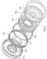
- Figure 2 shows an exploded view of the same assembly as Figure 1 from the opposite side showing the stator 252 comprising the rear stator wall 230 and coil and electronics assembly 231.
- the rotor 240 comprises the outer rotor wall 220 and circumferential wall 221 within which magnets 242 are circumferentially arranged.
- the stator 252 is connected to the rotor 240 via the bearing block at the central portions of the rotor and stator walls.
- control devices 80 carrying control electronics, otherwise known as motor drive controllers or inverters.
- a V shaped seal 350 is provided between the circumferential wall 221 of the rotor and the outer edge of the stator housing 230.
- the rotor also includes a set of magnets 227 for position sensing, otherwise known as commutation magnets, which in conjunction with sensors mounted on the stator allows for a rotor flux angle to be estimated.
- the rotor flux angle defines the positional relationship of the drive magnets to the coil windings.
- the rotor may include a ring of magnetic material that has multiple poles that act as a set of separate magnets.
- each drive magnet has an associated commutation magnet, where the rotor flux angle is derived from the flux angle associated with the set of commutation magnets by calibrating the measured commutation magnet flux angle.
- the set of commutation magnets has the same number of magnet or magnet pole pairs as the set of drive magnet pairs, where the commutation magnets and associated drive magnets are approximately radially aligned with each other. Accordingly, for the purposes of the present embodiment the set of commutation magnets has 32 magnet pairs, where each magnet pair is approximately radially aligned with a respective drive magnet pair.
- a sensor which in this embodiment is a Hall sensor, is mounted on the stator.
- the sensor is positioned so that as the rotor rotates each of the commutation magnets that form the commutation magnet ring respectively rotates past the sensor.
- the commutation magnets correspondingly rotate past the sensor with the Hall sensor outputting an AC voltage signal, where the sensor outputs a complete voltage cycle of 360 electrical degrees for each magnet pair that passes the respective sensors.
- the senor may also have an associated second sensor placed 90 electrical degrees apart.
- the motor 40 in this embodiment includes 8 coil sets 60 with each coil set 60 having three coil sub-sets 61, 62, 63 that are coupled to a respective control device 80, where each control device 80 and respective coil sub-sets form a three phase logical or sub electric motor that can be controlled independently of the other sub motors.
- the control devices 80 drive their respective sub motor with a three phase voltage supply, thereby allowing the respective coil sub-sets to generate a rotating magnetic field.
- each coil set 60 describes each coil set 60 as having three coil sub-sets 61, 62, 63, the present invention is not limited by this and it would be appreciated that each coil set 60 could have two or more coil sub-sets.
- the present embodiment describes an electric motor having eight coil sets 60 (i.e. eight sub motors) the motor could have one or more coil sets with an associated control device.
- Each control device includes a three phase bridge inverter which, as is well known to a person skilled in the art, contains six switches.
- the three phase bridge inverter is coupled to the three subset coils of a coil set 60 to form a three phase electric motor configuration.
- the motor includes eight three phase sub-motors, where each three phase sub-motor includes a control device 80 coupled to the three sub-set coils of a coil set 60.
- Each three phase bridge inverter is arranged to provide PWM voltage control across the respective coil sub-sets 61, 62, 63 to provide a required torque for the respective sub-motors.
- the three phase bridge switches of a control device 64 are arranged to apply a single voltage phase across each of the coil sub-sets 61, 62, 63.
- the in-wheel electric motor described in the present embodiment includes a plurality of logical sub-motors, as person skilled in the art would appreciate the electric motor may be of a conventional design without the use of logical sub-motors.
- each control device 80 is substantially wedge-shaped. This shape allows multiple control devices 80 to be located adjacent each other within the motor, forming a fan-like arrangement.
- the control device 80 switches can include semiconductor devices such as MOSFETs or IGBTs.
- the switches comprise IGBTs.
- any suitable known switching circuit can be employed for controlling the current.
- One well known example of such a switching circuit is the three phase bridge circuit having six switches configured to drive a three phase electric motor. The six switches are configured as three parallel sets of two switches, where each pair of switches is placed in series and from a leg of the three phase bridge circuit.
- the plurality of switches are arranged to apply an alternating voltage across the respective coil sub-sets.
- the plurality of switches are configured to form an n-phase bridge circuit. Accordingly, as is well known to a person skilled in the art, the number of switches will depend upon the number of voltage phases to be applied to the respective sub motors. Although the current design shows each sub motor having a three phase construction, the sub motors can be constructed to have two or more phases.
- the wires (e.g. copper wires) of the coil sub-sets can be connected directly to the switching devices as appropriate.
- the control device 80 includes a number of electrical components for controlling the operation of the switches mounted on the control device 80.
- electrical components mounted on the control device 80 include control logic for controlling the operation of the switches for providing PWM voltage control and interface components, such as a CAN interface chip, for allowing the control device 80 to communicate with devices external to the control device 80, such as other control devices 80 or a motor controller.
- the control device 80 will communicate over the interface to receive torque demand requests and to transmit status information.
- the sensor for determining the rotor flux angle will be mounted on a control device 80, which in turn will be mounted to the stator.
- a sensor may be mounted to each control device 80.
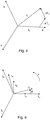
- the sinusoidal voltage waveforms generated in the electric motor by the control devices 80 under the control of a motor controller are created using Field Orientation Control, where the resultant rotor flux and stator currents are represented by respective vectors which are separated by 120 degrees as illustrated in Figure 4 by the three axes a, b, c.
- Field Oriented Control is based on projections that transform a two co-ordinate time invariant system, where a stator current or voltage component is aligned with a quadrature axis q and a magnetic flux component is aligned with a direct axis d, into a three phase time and speed dependent system and vice versa.
- a required torque ⁇ which is represented by an input i q * value
- a required magnetic flux ⁇ which is represented by an input i d * value
- the closed loop control system 100 illustrated in Figure 5 includes a Proportional Integral PI controller located between the respective motor input id* and iq* current demands, which correspond to driver torque demand, and the coil windings of the electric motor.
- the closed loop control system 100 includes current sensors for measuring current flow in the coil windings of the electric motor. To determine the corresponding id and iq current values a Clarke Transform and a Park Transform are used.
- a Clarke Transform uses three phase currents ia, ib, and ic that flow in the respective stator coils, which drive the electric motor, to calculate currents in a two phase orthogonal stator axis system i ⁇ and i ⁇ .
- a Park transformation is then performed by a Park Transform to transform the two fixed co-ordinate stator axes i ⁇ and i ⁇ to the two co-ordinate time invariant system id and iq, which defines a d, q rotating reference frame.
- Figure 6 illustrates the relationship of the stator current in the d,q rotating reference frame with respect to the two phase orthogonal stator axes i ⁇ and i ⁇ and the a, b and c stationary reference frame.
- the rotor phase angle ⁇ r otherwise known as rotor flux angle of the drive magnets, which is defined by the rotor magnetic flux vector ⁇ R
- the stator electrical phase angle ⁇ e should ideally be aligned with the q-axis, thereby maintaining synchronization between the rotor phase angle ⁇ r and the stator electrical phase angle ⁇ e .
- the rotor phase angle ⁇ r is provided to the Park Transform, where the rotor phase angle ⁇ r is determined using the rotor commutation magnets and position sensor mounted on the control device 80.
- the measured id and iq values are fedback to the respective input id* and iq* current values, where an error value based on the difference between the measured id and iq currents and the driver torque demand (i.e. the id* and iq* current demand) is calculated.
- the respective error values for id and iq are fed to the respective PI controller.
- the PI controllers determine the respective vd and vq values (i.e. the PI controller's manipulated variables) for driving the electric motor.
- the PWM voltage used to generate the ia, ib, and ic currents that flow in respective coil windings are derived from the vd and vq values via the use of an inverse Park Transform, as is well known to a person skilled in the art.
- any control loop feedback mechanism may be utilized.
- an estimate of the motor id and iq current is calculated using the input vd and vq voltages generated by the respective PI controllers.
- Any suitable means for determining the values of R s , L s d , L s q , ⁇ e and ⁇ m may be used, for example by measurement.
- Equ. 2 To obtain an estimates for i d and i q , Equ. 2 is integrated.
- T e the electrical torque
- N P the number of motor pole pairs.
- the torque generated by the electric motor is proportional to iq when id equals zero or L s d equals L s q .
- the estimated id and iq current values derived from equations 2 are compared with the measured id and iq current values.
- a counter value is increased. Any suitable means may be used to identify the first predetermined value, for example by experimentation or based on specific faults that are induced in the electric motor. However, if the first predetermined value is set too low there will be a greater likelihood that transient conditions will be falsely identified as a fault. In contrast, if the first predetermined value is set too high failure conditions in the electric motor may not be identified.
- the counter value is decreased.
- the present embodiment compares measured id and/or iq values with estimated id and iq values, a comparison may be made with other motor parameters, for example estimated and measured values of torque or power.
- the frequency at which the comparison of the estimated and measured values is made will typically be based upon the amount of time before which a fault condition becomes critical. For example, if a fault condition needs to be identified within 500 ms and the comparison is performed every 100 ms, a count value of 5 would indicate that a fault has occurred. If the comparison is performed very 50 ms, a count value of 10 would indicate that a fault has occurred.
- a fault indicator may be set to notify the driver of the vehicle that the vehicle should be taken to a service/diagnostic centre and/or the performance of the electric motor may be limited, for example the motor torque may be reduced or a reduced maximum torque set.
- Using a fault counter that is incremented and decremented based on the difference between estimated and measured current values has the advantage of minimising the risk of transient or noisy conditions being identified as a fault condition, where an out of tolerance condition is only identified as a fault if the condition continues for a predetermined time period or is identified a predetermined number of times.
- the input vq and vd voltages for the respective sub-motors may be compared.
- the first predetermined value can be determined by any suitable means.
- the input vq and vd voltages for three sub-motors are compared.
- the counter value is decreased.
- this embodiment compares respective sub-motor vq and vd values, a comparison may be made with other motor parameters, for example current.
- a fault indicator may be set to notify the driver of the vehicle that the vehicle should be taken to a service/diagnostic centre and/or the performance of the electric motor may be limited, for example the motor torque may be reduced or a reduced maximum torque set.
- Both of the embodiments for identifying a fault in an electric motor described above may be implemented in an electric motor together or separately.
Landscapes
- Engineering & Computer Science (AREA)
- Power Engineering (AREA)
- Transportation (AREA)
- Mechanical Engineering (AREA)
- Sustainable Development (AREA)
- Sustainable Energy (AREA)
- Life Sciences & Earth Sciences (AREA)
- General Physics & Mathematics (AREA)
- Physics & Mathematics (AREA)
- Control Of Ac Motors In General (AREA)
- Control Of Motors That Do Not Use Commutators (AREA)
- Electric Propulsion And Braking For Vehicles (AREA)
- Control Of Eletrric Generators (AREA)
- Protection Of Generators And Motors (AREA)
Description
- The present invention relates to a control unit for an electric motor or generator and in particular a control unit for identifying a fault in an electric motor or generator.
- With increased interested being placed in environmentally friendly vehicles there has been a corresponding increase in interest in the use of electric vehicles.
- Electric vehicles typically use an electric motor to provide both drive for the vehicle and regenerative braking for stopping the vehicle. To effect regenerative braking, rotary motion of a drive wheel connected to an electric motor is converted into electric energy.
- However, when using an electric motor in an automotive application it is desirable that the electric motor does not cause unintended acceleration or braking to occur.
- Accordingly, it is desirable for an electric motor to have sensors for measuring/monitoring electric motor parameters, where a fault will typically be identified if an electric motor parameter exceeds a threshold value.
- However, by determining whether a fault has occurred based directly on measured parameter values can result in one off spurious measurements being incorrectly identified as a fault. Further the types of faults identifiable in an electric motor will be limited by the number of parameters being measured.
-
US 6,392,418 describes a method and system for diagnostics for an electric motor that includes measuring a current from a direct current bus; capturing a torque current; calculating a current error; establishing a bound limit for the torque current and comparing the current error to the bound limit. - It is desirable to improve this situation.
- In accordance with an aspect of the present invention there is provided a method and a control unit for an electric motor or generator according to the accompanying claims.
- The invention as claimed provides the advantage of reducing the risk of falsely identifying transient or noise conditions or spurious one off measurements within an electric motor as fault conditions. The control unit of the invention is disclosed in claim 1 and the method of the invention is disclosed in claim 7. Claims 2 to 6 and 8 to 10 are related to preferred embodiments of the invention.
- The present invention will now be described, by way of example, with reference to the accompanying drawings, in which:
-
Figure 1 illustrates an exploded view of an electric motor as used in an embodiment of the present invention; -
Figure 2 illustrates an exploded view of the electric motor shown infigure 1 from an alternative angle; -
Figure 3 illustrates an example arrangement of coil sets for an electric motor according to an embodiment of the present invention; -
Figure 4 illustrates a three phase stator current complex space vector; -
Figure 5 illustrates a closed loop control system for an electric motor according to an embodiment of the present invention; -
Figure 6 illustrates a three phase stator current reference frame with a d, q rotating reference frame. - The embodiment of the invention described is a control unit for an electric motor for use in a wheel of a vehicle. However, the control unit can be located remotely to the electric motor. The motor is of the type having a set of coils being part of the stator for attachment to a vehicle, radially surrounded by a rotor carrying a set of magnets for attachment to a wheel. For the avoidance of doubt, the various aspects of the invention are equally applicable to an electric generator having the same arrangement. As such, the definition of electric motor is intended to include electric generator. In addition, some of the aspects of the invention are applicable to an arrangement having the rotor centrally mounted within radially surrounding coils. As would be appreciated by a person skilled in the art, the present invention is applicable for use with other types of electric motors.
- For the purposes of the present embodiment, as illustrated in
Figure 1 , the in-wheelelectric motor 40 includes astator 252 comprising arear portion 230 forming a first part of the housing of the assembly, and a heat sink anddrive arrangement 231 comprising multiple coils and electronics to drive the coils. Thecoil drive arrangement 231 is fixed to therear portion 230 to form thestator 252 which may then be fixed to a vehicle and does not rotate relative to the vehicle during use. The coils themselves are formed on tooth laminations to form coil windings, which together with thedrive arrangement 231 andrear portion 230 form thestator 252. - A
rotor 240 comprises afront portion 220 and acylindrical portion 221 forming a cover, which substantially surrounds thestator 252. The rotor includes a plurality ofpermanent magnets 242 arranged around the inside of thecylindrical portion 221. For the purposes of the present embodiment 32 magnet pairs are mounted on the inside of thecylindrical portion 221. However, any number of magnet pairs may be used. - The magnets are in close proximity to the coils on the
assembly 231 so that magnetic fields generated by the coils in theassembly 231 interact with themagnets 242 arranged around the inside of thecylindrical portion 221 of therotor 240 to cause therotor 240 to rotate. As thepermanent magnets 242 are utilized to generate a drive torque for driving the electric motor, the permanent magnets are typically called drive magnets. - The
rotor 240 is attached to thestator 252 by abearing block 223. Thebearing block 223 can be a standard bearing block as would be used in a vehicle to which this motor assembly is to be fitted. The bearing block comprises two parts, a first part fixed to the stator and a second part fixed to the rotor. The bearing block is fixed to a central portion 233 of thewall 230 of thestator 252 and also to a central portion 225 of thehousing wall 220 of therotor 240. Therotor 240 is thus rotationally fixed to the vehicle with which it is to be used via thebearing block 223 at the central portion 225 of therotor 240. This has an advantage in that a wheel rim and tyre can then be fixed to therotor 240 at the central portion 225 using the normal wheel bolts to fix the wheel rim to the central portion of the rotor and consequently firmly onto the rotatable side of thebearing block 223. The wheel bolts may be fitted through the central portion 225 of the rotor through into the bearing block itself. With both therotor 240 and the wheel being mounted to thebearing block 223 there is a one to one correspondence between the angle of rotation of the rotor and the wheel. -
Figure 2 shows an exploded view of the same assembly asFigure 1 from the opposite side showing thestator 252 comprising therear stator wall 230 and coil andelectronics assembly 231. Therotor 240 comprises theouter rotor wall 220 andcircumferential wall 221 within whichmagnets 242 are circumferentially arranged. As previously described, thestator 252 is connected to therotor 240 via the bearing block at the central portions of the rotor and stator walls. - Additionally shown in
Figure 1 arecontrol devices 80 carrying control electronics, otherwise known as motor drive controllers or inverters. - A V shaped
seal 350 is provided between thecircumferential wall 221 of the rotor and the outer edge of thestator housing 230. - The rotor also includes a set of
magnets 227 for position sensing, otherwise known as commutation magnets, which in conjunction with sensors mounted on the stator allows for a rotor flux angle to be estimated. The rotor flux angle defines the positional relationship of the drive magnets to the coil windings. Alternatively, in place of a set of separate magnets the rotor may include a ring of magnetic material that has multiple poles that act as a set of separate magnets. - To allow the commutation magnets to be used to calculate a rotor flux angle, preferably each drive magnet has an associated commutation magnet, where the rotor flux angle is derived from the flux angle associated with the set of commutation magnets by calibrating the measured commutation magnet flux angle. To simplify the correlation between the commutation magnet flux angle and the rotor flux angle, preferably the set of commutation magnets has the same number of magnet or magnet pole pairs as the set of drive magnet pairs, where the commutation magnets and associated drive magnets are approximately radially aligned with each other. Accordingly, for the purposes of the present embodiment the set of commutation magnets has 32 magnet pairs, where each magnet pair is approximately radially aligned with a respective drive magnet pair.
- A sensor, which in this embodiment is a Hall sensor, is mounted on the stator. The sensor is positioned so that as the rotor rotates each of the commutation magnets that form the commutation magnet ring respectively rotates past the sensor.
- As the rotor rotates relative to the stator the commutation magnets correspondingly rotate past the sensor with the Hall sensor outputting an AC voltage signal, where the sensor outputs a complete voltage cycle of 360 electrical degrees for each magnet pair that passes the respective sensors.
- To aid in the determination of the direction of the rotor, the sensor may also have an associated second sensor placed 90 electrical degrees apart.
- As illustrated in
Figure 3 , themotor 40 in this embodiment includes 8coil sets 60 with each coil set 60 having threecoil sub-sets respective control device 80, where eachcontrol device 80 and respective coil sub-sets form a three phase logical or sub electric motor that can be controlled independently of the other sub motors. Thecontrol devices 80 drive their respective sub motor with a three phase voltage supply, thereby allowing the respective coil sub-sets to generate a rotating magnetic field. Although the present embodiment describes each coil set 60 as having threecoil sub-sets - Each control device includes a three phase bridge inverter which, as is well known to a person skilled in the art, contains six switches. The three phase bridge inverter is coupled to the three subset coils of a coil set 60 to form a three phase electric motor configuration. Accordingly, as stated above, the motor includes eight three phase sub-motors, where each three phase sub-motor includes a
control device 80 coupled to the three sub-set coils of acoil set 60. - Each three phase bridge inverter is arranged to provide PWM voltage control across the
respective coil sub-sets - For a given coil set the three phase bridge switches of a
control device 64 are arranged to apply a single voltage phase across each of thecoil sub-sets - Although the in-wheel electric motor described in the present embodiment includes a plurality of logical sub-motors, as person skilled in the art would appreciate the electric motor may be of a conventional design without the use of logical sub-motors.
- In this embodiment, each
control device 80 is substantially wedge-shaped. This shape allowsmultiple control devices 80 to be located adjacent each other within the motor, forming a fan-like arrangement. - The
control device 80 switches can include semiconductor devices such as MOSFETs or IGBTs. In the present example, the switches comprise IGBTs. However, any suitable known switching circuit can be employed for controlling the current. One well known example of such a switching circuit is the three phase bridge circuit having six switches configured to drive a three phase electric motor. The six switches are configured as three parallel sets of two switches, where each pair of switches is placed in series and from a leg of the three phase bridge circuit. - The plurality of switches are arranged to apply an alternating voltage across the respective coil sub-sets.
- As described above, the plurality of switches are configured to form an n-phase bridge circuit. Accordingly, as is well known to a person skilled in the art, the number of switches will depend upon the number of voltage phases to be applied to the respective sub motors. Although the current design shows each sub motor having a three phase construction, the sub motors can be constructed to have two or more phases.
- The wires (e.g. copper wires) of the coil sub-sets can be connected directly to the switching devices as appropriate.
- The
control device 80 includes a number of electrical components for controlling the operation of the switches mounted on thecontrol device 80. Examples of electrical components mounted on thecontrol device 80 include control logic for controlling the operation of the switches for providing PWM voltage control and interface components, such as a CAN interface chip, for allowing thecontrol device 80 to communicate with devices external to thecontrol device 80, such asother control devices 80 or a motor controller. Typically thecontrol device 80 will communicate over the interface to receive torque demand requests and to transmit status information. Typically, the sensor for determining the rotor flux angle will be mounted on acontrol device 80, which in turn will be mounted to the stator. Optionally, for additional redundancy a sensor may be mounted to eachcontrol device 80. - The sinusoidal voltage waveforms generated in the electric motor by the
control devices 80 under the control of a motor controller (not shown) are created using Field Orientation Control, where the resultant rotor flux and stator currents are represented by respective vectors which are separated by 120 degrees as illustrated inFigure 4 by the three axes a, b, c. - As illustrated in
Figure 4 , currents ia, ib, ic represent the instantaneous current in the respective stator coils in the A, B, and C axis of a three phase current reference frame, where the stator current vector is defined by is = ia + αib + α 2 ic, where α = e(i*2*π/3). - Field Oriented Control is based on projections that transform a two co-ordinate time invariant system, where a stator current or voltage component is aligned with a quadrature axis q and a magnetic flux component is aligned with a direct axis d, into a three phase time and speed dependent system and vice versa.
- Using a closed loop control system, an example of one being illustrated in
Figure 5 , a required torque τ, which is represented by an input iq* value, and a required magnetic flux λ, which is represented by an input id* value, are generated in the electric motor. - It should be noted, however, that under normal circumstances a permanent magnet synchronous electric motor will typically have id set to zero.
- The closed loop control system 100 illustrated in
Figure 5 includes a Proportional Integral PI controller located between the respective motor input id* and iq* current demands, which correspond to driver torque demand, and the coil windings of the electric motor. - The closed loop control system 100 includes current sensors for measuring current flow in the coil windings of the electric motor. To determine the corresponding id and iq current values a Clarke Transform and a Park Transform are used.
- A Clarke Transform uses three phase currents ia, ib, and ic that flow in the respective stator coils, which drive the electric motor, to calculate currents in a two phase orthogonal stator axis system iα and iβ. A Park transformation is then performed by a Park Transform to transform the two fixed co-ordinate stator axes iα and iβ to the two co-ordinate time invariant system id and iq, which defines a d, q rotating reference frame.
Figure 6 illustrates the relationship of the stator current in the d,q rotating reference frame with respect to the two phase orthogonal stator axes iα and iβ and the a, b and c stationary reference frame. - Under normal drive conditions the rotor phase angle θ r, otherwise known as rotor flux angle of the drive magnets, which is defined by the rotor magnetic flux vector ΨR, and the stator electrical phase angle θ e should ideally be aligned with the q-axis, thereby maintaining synchronization between the rotor phase angle θ r and the stator electrical phase angle θ e.
- To allow the Park Transform 102 to derive a time invariant transformation the rotor phase angle θ r is provided to the Park Transform, where the rotor phase angle θ r is determined using the rotor commutation magnets and position sensor mounted on the
control device 80. - The measured id and iq values are fedback to the respective input id* and iq* current values, where an error value based on the difference between the measured id and iq currents and the driver torque demand (i.e. the id* and iq* current demand) is calculated.
- The respective error values for id and iq are fed to the respective PI controller.
- Based on the error values provided to the respective PI controller, the PI controllers determine the respective vd and vq values (i.e. the PI controller's manipulated variables) for driving the electric motor. The PWM voltage used to generate the ia, ib, and ic currents that flow in respective coil windings are derived from the vd and vq values via the use of an inverse Park Transform, as is well known to a person skilled in the art.
- Although the present embodiment utilizes a PI controller feedback loop, any control loop feedback mechanism may be utilized.
- A process for identifying fault conditions associated with an electric motor according to a first embodiment will now be described.
- Using a model of an electric motor, which according to the present embodiment is a permanent magnet synchronous electric motor, an estimate of the motor id and iq current is calculated using the input vd and vq voltages generated by the respective PI controllers.
- For example, a permanent magnet motor can be modeled using voltage equations:

d and Lsq are the components of inductance of the stator coil windings, ωe is the electrical frequency and ψm is the flux resulting from the permanent magnets. - Any suitable means for determining the values of Rs, Ls
d , Lsq , ωe and ψm may be used, for example by measurement. - To provide expressions for the rate of change of current the voltage equations are rearranged as illustrated in Equ. 2.

- To obtain an estimates for id and iq, Equ. 2 is integrated.
- The estimated id and iq values may be used to provide an estimate for the torque generated by the motor using a torque equation, for example:

d equals Lsq . - The estimated id and iq current values derived from equations 2 are compared with the measured id and iq current values.
- If the difference between the estimated id and/or iq values and the measured id and/or iq values are greater than a first predetermined value a counter value is increased. Any suitable means may be used to identify the first predetermined value, for example by experimentation or based on specific faults that are induced in the electric motor. However, if the first predetermined value is set too low there will be a greater likelihood that transient conditions will be falsely identified as a fault. In contrast, if the first predetermined value is set too high failure conditions in the electric motor may not be identified.
- If the difference between the estimated id and/or iq values and the measured id and/or iq values are less than the first predetermined value the counter value is decreased.
- Although the present embodiment compares measured id and/or iq values with estimated id and iq values, a comparison may be made with other motor parameters, for example estimated and measured values of torque or power.
- If the counter value exceeds a second predetermined value this indicates that there is a fault with the electric motor and a fault condition is triggered.
- The frequency at which the comparison of the estimated and measured values is made will typically be based upon the amount of time before which a fault condition becomes critical. For example, if a fault condition needs to be identified within 500 ms and the comparison is performed every 100 ms, a count value of 5 would indicate that a fault has occurred. If the comparison is performed very 50 ms, a count value of 10 would indicate that a fault has occurred.
- Any suitable fault notification may be utilised, for example a fault indicator may be set to notify the driver of the vehicle that the vehicle should be taken to a service/diagnostic centre and/or the performance of the electric motor may be limited, for example the motor torque may be reduced or a reduced maximum torque set.
- Using a fault counter that is incremented and decremented based on the difference between estimated and measured current values has the advantage of minimising the risk of transient or noisy conditions being identified as a fault condition, where an out of tolerance condition is only identified as a fault if the condition continues for a predetermined time period or is identified a predetermined number of times.
- According to the claimed invention, for an electric motor having a plurality of sub-motors, as described above, the input vq and vd voltages for the respective sub-motors may be compared.
- If the difference between the input vq and vd voltages between two sub-motors is greater than a first predetermined value a counter value is increased. As with the first embodiment, the first predetermined value can be determined by any suitable means. Preferably, to aid the location of a fault condition to a specific sub-motor the input vq and vd voltages for three sub-motors are compared.
- If the difference between the respective vq and vd values are less than the first predetermined value the counter value is decreased.
- Although, this embodiment compares respective sub-motor vq and vd values, a comparison may be made with other motor parameters, for example current.
- If the counter value exceeds a second predetermined value this indicates that there is a fault with one or more of the sub-motors and a fault condition is triggered.
- Any suitable fault condition may be utilised, for example a fault indicator may be set to notify the driver of the vehicle that the vehicle should be taken to a service/diagnostic centre and/or the performance of the electric motor may be limited, for example the motor torque may be reduced or a reduced maximum torque set.
- Both of the embodiments for identifying a fault in an electric motor described above may be implemented in an electric motor together or separately.
Claims (10)
- A control unit (80) for identifying a fault in an electric motor having a plurality of sub-motors the control unit comprising means for measuring a value of a first parameter associated with the operation of a first sub motor of the electric motor or generator, and means for measuring a value of a first parameter associated with the operation of a second sub motor of the electric motor or generator; means for increasing a counter value if the difference between the measured first parameter value associated with the operation of the first sub motor or a value derived from the measured value and a second value is greater than a first predetermined value; means for decreasing the counter value if the difference between the measured first parameter value associated with the operation of the first sub motor and the second value is less than the first predetermined value; and means for generating a signal indicative of a fault if the counter value exceeds a second predetermined value, wherein the second value is the measured value of the first parameter associated with the second sub motor.
- A control unit according to claim 1, wherein the first parameter is a voltage or current generated in a coil winding of the electric motor or generator.
- A control unit according to claim 2, wherein the first parameter is a component of voltage or current.
- A control unit according to claim 1, wherein the first parameter is the torque or power generated by the electric motor or generator.
- An electric motor system comprising an electric motor and a control unit according to any one of the preceding claims.
- An electric motor system according to claim 5, wherein the electric motor is a permanent magnet synchronous electric motor.
- A method for identifying a fault in an electric motor having a plurality of sub-motors the method comprising measuring a value of a first parameter associated with the operation of a first sub motor of the electric motor or generator, and measuring a value of a first parameter associated with the operation of a second sub motor of the electric motor or generator; increasing a counter value if the difference between the measured first parameter value associated with the operation of the first sub motor or a value derived from the measured value and a second value is greater than a first predetermined value; decreasing the counter value if the difference between the measured first parameter value associated with the operation of the first sub motor and the second value is less than the first predetermined value; and generating a signal indicative of a fault if the counter value exceeds a second predetermined value, wherein the second value is the measured value of the first parameter associated with the second sub motor.
- A method according to claim 7, wherein the first parameter is a voltage or current generated in a coil winding of the electric motor or generator.
- A method according to claim 8, wherein the first parameter is a component of voltage or current.
- A method according to claim 7, wherein the first parameter is the torque or power generated by the electric motor or generator.
Applications Claiming Priority (2)
| Application Number | Priority Date | Filing Date | Title |
|---|---|---|---|
| GB201210799A GB2503217B (en) | 2012-06-18 | 2012-06-18 | A method and control unit for an electric motor or generator |
| PCT/IB2013/054782 WO2013190429A2 (en) | 2012-06-18 | 2013-06-11 | A Method and Control Unit for an Electric Motor or Generator |
Publications (2)
| Publication Number | Publication Date |
|---|---|
| EP2862270A2 EP2862270A2 (en) | 2015-04-22 |
| EP2862270B1 true EP2862270B1 (en) | 2021-07-14 |
Family
ID=46641109
Family Applications (1)
| Application Number | Title | Priority Date | Filing Date |
|---|---|---|---|
| EP13747502.6A Active EP2862270B1 (en) | 2012-06-18 | 2013-06-11 | A method and control unit for an electric motor or generator |
Country Status (5)
| Country | Link |
|---|---|
| US (1) | US9423463B2 (en) |
| EP (1) | EP2862270B1 (en) |
| CN (2) | CN104380595A (en) |
| GB (1) | GB2503217B (en) |
| WO (1) | WO2013190429A2 (en) |
Families Citing this family (6)
| Publication number | Priority date | Publication date | Assignee | Title |
|---|---|---|---|---|
| GB2534895B (en) * | 2015-02-04 | 2017-06-07 | Protean Electric Ltd | A bearing arrangement for an electric motor or generator |
| US10476360B2 (en) | 2016-09-13 | 2019-11-12 | Indigo Technologies, Inc. | Axial flux motor having rotatably coupled coil stator assemblies and methods of using same |
| FR3063546B1 (en) * | 2017-03-06 | 2019-03-29 | Safran Electronics & Defense | METHOD FOR MONITORING EQUIPMENT OF ELECTROMECHANICAL ACTUATOR TYPE |
| CN108775857B (en) * | 2018-07-09 | 2019-11-22 | 西北工业大学 | Fault Diagnosis Method of Hall Position Sensor of Permanent Magnet Brushless Motor |
| US11654780B2 (en) | 2020-12-17 | 2023-05-23 | Consolidated Metco, Inc. | Vehicle electronic control unit and method |
| DE102022119059A1 (en) * | 2022-07-29 | 2024-02-01 | Bayerische Motoren Werke Aktiengesellschaft | Method and device for monitoring an electric drive of a motor vehicle |
Family Cites Families (10)
| Publication number | Priority date | Publication date | Assignee | Title |
|---|---|---|---|---|
| DE10037972B4 (en) * | 1999-08-05 | 2005-09-15 | Sharp K.K. | Device and method for electric motor control |
| US6392418B1 (en) * | 1999-09-16 | 2002-05-21 | Delphi Technologies, Inc. | Torque current comparison for current reasonableness diagnostics in a permanent magnet electric machine |
| US7136733B2 (en) * | 2003-08-28 | 2006-11-14 | Motorola, Inc. | Fault detection in an electric power-assisted steering system |
| JP4049126B2 (en) * | 2004-06-09 | 2008-02-20 | ソニー株式会社 | Motor drive circuit, electronic device, and motor drive method |
| US7483796B2 (en) * | 2004-12-08 | 2009-01-27 | Trw Automotive U.S. Llc | Method and apparatus for determining faults in an electric assist steering system |
| DE102005062873A1 (en) * | 2005-12-29 | 2007-07-19 | Robert Bosch Gmbh | Method for operating a control and / or regulating device, preferably for a drive machine of a motor vehicle |
| JP4320743B2 (en) * | 2007-03-02 | 2009-08-26 | 株式会社デンソー | Rotating machine control device |
| DE102007031769B4 (en) * | 2007-07-07 | 2009-07-16 | Dr. Ing. H.C. F. Porsche Aktiengesellschaft | Method for monitoring a function computer in a control unit |
| US7956762B2 (en) * | 2008-09-15 | 2011-06-07 | Caterpillar Inc. | Method and apparatus for power generation failure diagnostics |
| US8314576B2 (en) * | 2009-07-17 | 2012-11-20 | Board Of Regents, The University Of Texas System | Methods and apparatuses for fault management in permanent magnet synchronous machines using the field reconstruction method |
-
2012
- 2012-06-18 GB GB201210799A patent/GB2503217B/en active Active
-
2013
- 2013-06-11 WO PCT/IB2013/054782 patent/WO2013190429A2/en not_active Ceased
- 2013-06-11 CN CN201380032221.0A patent/CN104380595A/en active Pending
- 2013-06-11 CN CN201810232082.0A patent/CN108429510A/en active Pending
- 2013-06-11 EP EP13747502.6A patent/EP2862270B1/en active Active
- 2013-06-11 US US14/408,565 patent/US9423463B2/en active Active
Non-Patent Citations (1)
| Title |
|---|
| None * |
Also Published As
| Publication number | Publication date |
|---|---|
| CN104380595A (en) | 2015-02-25 |
| EP2862270A2 (en) | 2015-04-22 |
| US9423463B2 (en) | 2016-08-23 |
| CN108429510A (en) | 2018-08-21 |
| WO2013190429A3 (en) | 2014-02-06 |
| GB2503217B (en) | 2014-12-10 |
| WO2013190429A2 (en) | 2013-12-27 |
| WO2013190429A9 (en) | 2014-03-27 |
| GB2503217A (en) | 2013-12-25 |
| US20150185288A1 (en) | 2015-07-02 |
| GB201210799D0 (en) | 2012-08-01 |
Similar Documents
| Publication | Publication Date | Title |
|---|---|---|
| EP2771204B1 (en) | Electric motor or generator system | |
| EP2728736B1 (en) | Motor drive device | |
| JP6389879B2 (en) | Electric motor or generator | |
| EP3707819B1 (en) | A control device | |
| US9423463B2 (en) | Method and control unit for an electric motor or generator | |
| CN103840720B (en) | Control system for motor | |
| EP2566046B1 (en) | Motor control apparatus | |
| EP2566717B1 (en) | Electric motor for an electric vehicle | |
| CN106985705B (en) | control systems for vehicles | |
| EP3863880B1 (en) | A traction control system | |
| EP3544174B1 (en) | Rotating electric-machine-control apparatus and electric power steering apparatus equipped with said rotating-electric-machine control apparatus | |
| EP1821402B1 (en) | Motor control device and motor control method | |
| JP2018531572A6 (en) | Vehicle control system | |
| JP2016518105A (en) | Method for estimating the angular position of a rotor of a multiphase rotating electrical machine and its application to the control of a multiphase inverter for such a machine | |
| KR101982880B1 (en) | Electric device comprising an alternating current electric motor and a control inverter and a method for measuring the electromotive force of this device | |
| JP7599362B2 (en) | Fault determination device, fault determination program, and fault determination method | |
| JP2017034762A (en) | Control device for rotary electric machine, and control method for rotary electric machine | |
| JP2014057385A (en) | Controller of dynamo-electric machine and dynamo-electric machine drive system including the same | |
| US11283390B2 (en) | Controller for an electric machine | |
| KR20200059848A (en) | Apparatus and method for detecting BLDC motor overload |
Legal Events
| Date | Code | Title | Description |
|---|---|---|---|
| PUAI | Public reference made under article 153(3) epc to a published international application that has entered the european phase |
Free format text: ORIGINAL CODE: 0009012 |
|
| 17P | Request for examination filed |
Effective date: 20150119 |
|
| AK | Designated contracting states |
Kind code of ref document: A2 Designated state(s): AL AT BE BG CH CY CZ DE DK EE ES FI FR GB GR HR HU IE IS IT LI LT LU LV MC MK MT NL NO PL PT RO RS SE SI SK SM TR |
|
| AX | Request for extension of the european patent |
Extension state: BA ME |
|
| DAX | Request for extension of the european patent (deleted) | ||
| STAA | Information on the status of an ep patent application or granted ep patent |
Free format text: STATUS: EXAMINATION IS IN PROGRESS |
|
| 17Q | First examination report despatched |
Effective date: 20171114 |
|
| REG | Reference to a national code |
Ref country code: DE Ref legal event code: R079 Ref document number: 602013078332 Country of ref document: DE Free format text: PREVIOUS MAIN CLASS: H02P0029020000 Ipc: H02P0029024000 |
|
| RIC1 | Information provided on ipc code assigned before grant |
Ipc: H02P 29/024 20160101AFI20201125BHEP Ipc: B60L 3/00 20190101ALI20201125BHEP Ipc: B60L 15/02 20060101ALI20201125BHEP |
|
| GRAP | Despatch of communication of intention to grant a patent |
Free format text: ORIGINAL CODE: EPIDOSNIGR1 |
|
| STAA | Information on the status of an ep patent application or granted ep patent |
Free format text: STATUS: GRANT OF PATENT IS INTENDED |
|
| INTG | Intention to grant announced |
Effective date: 20210118 |
|
| GRAS | Grant fee paid |
Free format text: ORIGINAL CODE: EPIDOSNIGR3 |
|
| GRAA | (expected) grant |
Free format text: ORIGINAL CODE: 0009210 |
|
| STAA | Information on the status of an ep patent application or granted ep patent |
Free format text: STATUS: THE PATENT HAS BEEN GRANTED |
|
| AK | Designated contracting states |
Kind code of ref document: B1 Designated state(s): AL AT BE BG CH CY CZ DE DK EE ES FI FR GB GR HR HU IE IS IT LI LT LU LV MC MK MT NL NO PL PT RO RS SE SI SK SM TR |
|
| REG | Reference to a national code |
Ref country code: GB Ref legal event code: FG4D |
|
| REG | Reference to a national code |
Ref country code: IE Ref legal event code: FG4D |
|
| REG | Reference to a national code |
Ref country code: DE Ref legal event code: R096 Ref document number: 602013078332 Country of ref document: DE |
|
| REG | Reference to a national code |
Ref country code: AT Ref legal event code: REF Ref document number: 1411440 Country of ref document: AT Kind code of ref document: T Effective date: 20210815 |
|
| REG | Reference to a national code |
Ref country code: LT Ref legal event code: MG9D |
|
| REG | Reference to a national code |
Ref country code: NL Ref legal event code: MP Effective date: 20210714 |
|
| REG | Reference to a national code |
Ref country code: AT Ref legal event code: MK05 Ref document number: 1411440 Country of ref document: AT Kind code of ref document: T Effective date: 20210714 |
|
| PG25 | Lapsed in a contracting state [announced via postgrant information from national office to epo] |
Ref country code: SE Free format text: LAPSE BECAUSE OF FAILURE TO SUBMIT A TRANSLATION OF THE DESCRIPTION OR TO PAY THE FEE WITHIN THE PRESCRIBED TIME-LIMIT Effective date: 20210714 Ref country code: HR Free format text: LAPSE BECAUSE OF FAILURE TO SUBMIT A TRANSLATION OF THE DESCRIPTION OR TO PAY THE FEE WITHIN THE PRESCRIBED TIME-LIMIT Effective date: 20210714 Ref country code: RS Free format text: LAPSE BECAUSE OF FAILURE TO SUBMIT A TRANSLATION OF THE DESCRIPTION OR TO PAY THE FEE WITHIN THE PRESCRIBED TIME-LIMIT Effective date: 20210714 Ref country code: NL Free format text: LAPSE BECAUSE OF FAILURE TO SUBMIT A TRANSLATION OF THE DESCRIPTION OR TO PAY THE FEE WITHIN THE PRESCRIBED TIME-LIMIT Effective date: 20210714 Ref country code: NO Free format text: LAPSE BECAUSE OF FAILURE TO SUBMIT A TRANSLATION OF THE DESCRIPTION OR TO PAY THE FEE WITHIN THE PRESCRIBED TIME-LIMIT Effective date: 20211014 Ref country code: PT Free format text: LAPSE BECAUSE OF FAILURE TO SUBMIT A TRANSLATION OF THE DESCRIPTION OR TO PAY THE FEE WITHIN THE PRESCRIBED TIME-LIMIT Effective date: 20211115 Ref country code: ES Free format text: LAPSE BECAUSE OF FAILURE TO SUBMIT A TRANSLATION OF THE DESCRIPTION OR TO PAY THE FEE WITHIN THE PRESCRIBED TIME-LIMIT Effective date: 20210714 Ref country code: FI Free format text: LAPSE BECAUSE OF FAILURE TO SUBMIT A TRANSLATION OF THE DESCRIPTION OR TO PAY THE FEE WITHIN THE PRESCRIBED TIME-LIMIT Effective date: 20210714 Ref country code: LT Free format text: LAPSE BECAUSE OF FAILURE TO SUBMIT A TRANSLATION OF THE DESCRIPTION OR TO PAY THE FEE WITHIN THE PRESCRIBED TIME-LIMIT Effective date: 20210714 Ref country code: AT Free format text: LAPSE BECAUSE OF FAILURE TO SUBMIT A TRANSLATION OF THE DESCRIPTION OR TO PAY THE FEE WITHIN THE PRESCRIBED TIME-LIMIT Effective date: 20210714 Ref country code: BG Free format text: LAPSE BECAUSE OF FAILURE TO SUBMIT A TRANSLATION OF THE DESCRIPTION OR TO PAY THE FEE WITHIN THE PRESCRIBED TIME-LIMIT Effective date: 20211014 |
|
| PG25 | Lapsed in a contracting state [announced via postgrant information from national office to epo] |
Ref country code: PL Free format text: LAPSE BECAUSE OF FAILURE TO SUBMIT A TRANSLATION OF THE DESCRIPTION OR TO PAY THE FEE WITHIN THE PRESCRIBED TIME-LIMIT Effective date: 20210714 Ref country code: LV Free format text: LAPSE BECAUSE OF FAILURE TO SUBMIT A TRANSLATION OF THE DESCRIPTION OR TO PAY THE FEE WITHIN THE PRESCRIBED TIME-LIMIT Effective date: 20210714 Ref country code: GR Free format text: LAPSE BECAUSE OF FAILURE TO SUBMIT A TRANSLATION OF THE DESCRIPTION OR TO PAY THE FEE WITHIN THE PRESCRIBED TIME-LIMIT Effective date: 20211015 |
|
| REG | Reference to a national code |
Ref country code: DE Ref legal event code: R097 Ref document number: 602013078332 Country of ref document: DE |
|
| PG25 | Lapsed in a contracting state [announced via postgrant information from national office to epo] |
Ref country code: DK Free format text: LAPSE BECAUSE OF FAILURE TO SUBMIT A TRANSLATION OF THE DESCRIPTION OR TO PAY THE FEE WITHIN THE PRESCRIBED TIME-LIMIT Effective date: 20210714 |
|
| PLBE | No opposition filed within time limit |
Free format text: ORIGINAL CODE: 0009261 |
|
| STAA | Information on the status of an ep patent application or granted ep patent |
Free format text: STATUS: NO OPPOSITION FILED WITHIN TIME LIMIT |
|
| PG25 | Lapsed in a contracting state [announced via postgrant information from national office to epo] |
Ref country code: SM Free format text: LAPSE BECAUSE OF FAILURE TO SUBMIT A TRANSLATION OF THE DESCRIPTION OR TO PAY THE FEE WITHIN THE PRESCRIBED TIME-LIMIT Effective date: 20210714 Ref country code: SK Free format text: LAPSE BECAUSE OF FAILURE TO SUBMIT A TRANSLATION OF THE DESCRIPTION OR TO PAY THE FEE WITHIN THE PRESCRIBED TIME-LIMIT Effective date: 20210714 Ref country code: RO Free format text: LAPSE BECAUSE OF FAILURE TO SUBMIT A TRANSLATION OF THE DESCRIPTION OR TO PAY THE FEE WITHIN THE PRESCRIBED TIME-LIMIT Effective date: 20210714 Ref country code: EE Free format text: LAPSE BECAUSE OF FAILURE TO SUBMIT A TRANSLATION OF THE DESCRIPTION OR TO PAY THE FEE WITHIN THE PRESCRIBED TIME-LIMIT Effective date: 20210714 Ref country code: CZ Free format text: LAPSE BECAUSE OF FAILURE TO SUBMIT A TRANSLATION OF THE DESCRIPTION OR TO PAY THE FEE WITHIN THE PRESCRIBED TIME-LIMIT Effective date: 20210714 Ref country code: AL Free format text: LAPSE BECAUSE OF FAILURE TO SUBMIT A TRANSLATION OF THE DESCRIPTION OR TO PAY THE FEE WITHIN THE PRESCRIBED TIME-LIMIT Effective date: 20210714 |
|
| 26N | No opposition filed |
Effective date: 20220419 |
|
| PG25 | Lapsed in a contracting state [announced via postgrant information from national office to epo] |
Ref country code: MC Free format text: LAPSE BECAUSE OF FAILURE TO SUBMIT A TRANSLATION OF THE DESCRIPTION OR TO PAY THE FEE WITHIN THE PRESCRIBED TIME-LIMIT Effective date: 20210714 |
|
| REG | Reference to a national code |
Ref country code: CH Ref legal event code: PL |
|
| REG | Reference to a national code |
Ref country code: BE Ref legal event code: MM Effective date: 20220630 |
|
| GBPC | Gb: european patent ceased through non-payment of renewal fee |
Effective date: 20220611 |
|
| PG25 | Lapsed in a contracting state [announced via postgrant information from national office to epo] |
Ref country code: LU Free format text: LAPSE BECAUSE OF NON-PAYMENT OF DUE FEES Effective date: 20220611 Ref country code: LI Free format text: LAPSE BECAUSE OF NON-PAYMENT OF DUE FEES Effective date: 20220630 Ref country code: IE Free format text: LAPSE BECAUSE OF NON-PAYMENT OF DUE FEES Effective date: 20220611 Ref country code: CH Free format text: LAPSE BECAUSE OF NON-PAYMENT OF DUE FEES Effective date: 20220630 |
|
| PG25 | Lapsed in a contracting state [announced via postgrant information from national office to epo] |
Ref country code: GB Free format text: LAPSE BECAUSE OF NON-PAYMENT OF DUE FEES Effective date: 20220611 Ref country code: BE Free format text: LAPSE BECAUSE OF NON-PAYMENT OF DUE FEES Effective date: 20220630 |
|
| PG25 | Lapsed in a contracting state [announced via postgrant information from national office to epo] |
Ref country code: HU Free format text: LAPSE BECAUSE OF FAILURE TO SUBMIT A TRANSLATION OF THE DESCRIPTION OR TO PAY THE FEE WITHIN THE PRESCRIBED TIME-LIMIT; INVALID AB INITIO Effective date: 20130611 |
|
| PG25 | Lapsed in a contracting state [announced via postgrant information from national office to epo] |
Ref country code: MK Free format text: LAPSE BECAUSE OF FAILURE TO SUBMIT A TRANSLATION OF THE DESCRIPTION OR TO PAY THE FEE WITHIN THE PRESCRIBED TIME-LIMIT Effective date: 20210714 Ref country code: CY Free format text: LAPSE BECAUSE OF FAILURE TO SUBMIT A TRANSLATION OF THE DESCRIPTION OR TO PAY THE FEE WITHIN THE PRESCRIBED TIME-LIMIT Effective date: 20210714 |
|
| PG25 | Lapsed in a contracting state [announced via postgrant information from national office to epo] |
Ref country code: MT Free format text: LAPSE BECAUSE OF FAILURE TO SUBMIT A TRANSLATION OF THE DESCRIPTION OR TO PAY THE FEE WITHIN THE PRESCRIBED TIME-LIMIT Effective date: 20210714 |
|
| PGFP | Annual fee paid to national office [announced via postgrant information from national office to epo] |
Ref country code: DE Payment date: 20250604 Year of fee payment: 13 |
|
| PGFP | Annual fee paid to national office [announced via postgrant information from national office to epo] |
Ref country code: IT Payment date: 20250605 Year of fee payment: 13 |
|
| PGFP | Annual fee paid to national office [announced via postgrant information from national office to epo] |
Ref country code: FR Payment date: 20250530 Year of fee payment: 13 |
|
| PG25 | Lapsed in a contracting state [announced via postgrant information from national office to epo] |
Ref country code: TR Free format text: LAPSE BECAUSE OF FAILURE TO SUBMIT A TRANSLATION OF THE DESCRIPTION OR TO PAY THE FEE WITHIN THE PRESCRIBED TIME-LIMIT Effective date: 20210714 |