EP2861953B1 - Machine arrangement - Google Patents
Machine arrangement Download PDFInfo
- Publication number
- EP2861953B1 EP2861953B1 EP13728415.4A EP13728415A EP2861953B1 EP 2861953 B1 EP2861953 B1 EP 2861953B1 EP 13728415 A EP13728415 A EP 13728415A EP 2861953 B1 EP2861953 B1 EP 2861953B1
- Authority
- EP
- European Patent Office
- Prior art keywords
- glass fiber
- carrier
- metallic material
- machine arrangement
- nickel
- Prior art date
- Legal status (The legal status is an assumption and is not a legal conclusion. Google has not performed a legal analysis and makes no representation as to the accuracy of the status listed.)
- Not-in-force
Links
Images



Classifications
-
- C—CHEMISTRY; METALLURGY
- C03—GLASS; MINERAL OR SLAG WOOL
- C03C—CHEMICAL COMPOSITION OF GLASSES, GLAZES OR VITREOUS ENAMELS; SURFACE TREATMENT OF GLASS; SURFACE TREATMENT OF FIBRES OR FILAMENTS MADE FROM GLASS, MINERALS OR SLAGS; JOINING GLASS TO GLASS OR OTHER MATERIALS
- C03C27/00—Joining pieces of glass to pieces of other inorganic material; Joining glass to glass other than by fusing
- C03C27/04—Joining glass to metal by means of an interlayer
- C03C27/042—Joining glass to metal by means of an interlayer consisting of a combination of materials selected from glass, glass-ceramic or ceramic material with metals, metal oxides or metal salts
- C03C27/046—Joining glass to metal by means of an interlayer consisting of a combination of materials selected from glass, glass-ceramic or ceramic material with metals, metal oxides or metal salts of metals, metal oxides or metal salts only
-
- G—PHYSICS
- G01—MEASURING; TESTING
- G01M—TESTING STATIC OR DYNAMIC BALANCE OF MACHINES OR STRUCTURES; TESTING OF STRUCTURES OR APPARATUS, NOT OTHERWISE PROVIDED FOR
- G01M11/00—Testing of optical apparatus; Testing structures by optical methods not otherwise provided for
- G01M11/08—Testing mechanical properties
- G01M11/083—Testing mechanical properties by using an optical fiber in contact with the device under test [DUT]
- G01M11/086—Details about the embedment of the optical fiber within the DUT
-
- G—PHYSICS
- G01—MEASURING; TESTING
- G01L—MEASURING FORCE, STRESS, TORQUE, WORK, MECHANICAL POWER, MECHANICAL EFFICIENCY, OR FLUID PRESSURE
- G01L1/00—Measuring force or stress, in general
- G01L1/24—Measuring force or stress, in general by measuring variations of optical properties of material when it is stressed, e.g. by photoelastic stress analysis using infrared, visible light, ultraviolet
- G01L1/242—Measuring force or stress, in general by measuring variations of optical properties of material when it is stressed, e.g. by photoelastic stress analysis using infrared, visible light, ultraviolet the material being an optical fibre
- G01L1/246—Measuring force or stress, in general by measuring variations of optical properties of material when it is stressed, e.g. by photoelastic stress analysis using infrared, visible light, ultraviolet the material being an optical fibre using integrated gratings, e.g. Bragg gratings
-
- G—PHYSICS
- G01—MEASURING; TESTING
- G01M—TESTING STATIC OR DYNAMIC BALANCE OF MACHINES OR STRUCTURES; TESTING OF STRUCTURES OR APPARATUS, NOT OTHERWISE PROVIDED FOR
- G01M13/00—Testing of machine parts
- G01M13/04—Bearings
Definitions
- the glass fiber is basically free from any layer as described above. An exception can be that the glass fiber is encased by a reflective cover material to ensure the conduction of light through the glass fiber.
- the mentioned first metallic material can be a single metal element.
- the first metallic material is chromium (Cr).
- Ni nickel
- the second metallic material can be a metal alloy.
- the second metallic material can be an alloy of chromium (Cr) and nickel (Ni).
- the second metallic material can have at least partially a thickness measured in the direction perpendicular to the longitudinal axis of the glass fiber of at least 0.3 mm, preferably of at least 0.5 mm.
- the glass fiber can be attached to a cylindrical or flat surface of the machine arrangement. Also, it is possible to locate the glass fiber in a groove which is machined for the glass fiber into the machine arrangement.
- a further embodiment of the invention is shown.
- the glass fiber 2 is provided with a cladding 3' from a first metallic material being nickel (Ni).
- This cladding is embedded in a second metallic material 3" being a nickel-chromium-alloy.
- the second metallic material 3" is fixed on the carrier 1 by means of welding or brazing 4.
- the carrier 91 suitable comprises a groove with a diameter/depth in the range of 0.3 millimeter for a nickel coated optical fiber 92.
- a prepared optical fiber 92 suitably of the kind according to Fig. 8 , is put in the groove and a filling material 94 is added between the nickel coated fibers and the stainless steel carrier 91.
- the filling material can suitably be brazing alloy Cusin-1 ABA paste.
- the optical fiber 92 is then embedded into the carrier 91 by brazing, suitably vacuum brazing. After the optical fiber 92 has been embedded into or onto the carrier 91, the carrier 91 is then attached to a machine part which is to be measured as to for example temperature and/or strain.
Landscapes
- Chemical & Material Sciences (AREA)
- Physics & Mathematics (AREA)
- General Physics & Mathematics (AREA)
- Engineering & Computer Science (AREA)
- Ceramic Engineering (AREA)
- Life Sciences & Earth Sciences (AREA)
- Analytical Chemistry (AREA)
- Chemical Kinetics & Catalysis (AREA)
- General Chemical & Material Sciences (AREA)
- Geochemistry & Mineralogy (AREA)
- Materials Engineering (AREA)
- Organic Chemistry (AREA)
- Optical Transform (AREA)
Description
- The invention relates to a machine arrangement, comprising at least one carrier, wherein a glass fiber is connected with the machine arrangement, wherein the connection between the glass fiber and the machine arrangement is established by a metallic material which metal material is connected by material bonding with the machine arrangement as well as with the glass fiber.
- A machine arrangement of the generic kind is disclosed in
US 5 594 819 A . A similar solution is shown inGB 761 662 A - It is known in the art to equip a machine part of this kind with a glass fiber element to allow the measurement of different physical parameters. By doing so, a survey of the parameters becomes possible by using the fiber Bragg grating (FBG) method. By this method temperatures as well as strains of the machine arrangement can be monitored.
- For doing so it is necessary to connect a glass fiber with the component. For surveying temperatures it is essential that a thermal coupling between the glass fiber and the machine arrangement is established. For monitoring strains it is necessary to mechanically connect the glass fiber with the component to be monitored.
- Specifically in the latter case problems arise because the glass fiber is normally equipped with a plurality of coaxially arranged cover layers. A typical construction employs a cladding arranged around the glass fiber (core) itself; the cladding is coated by a coating layer. Then, strengthening fibers (made e. g. from aramid) are arranged at the outer circumference of the coating. Finally the strengthening fibers are cased by a hollow cylindrical cable jacket.
- When a glass fiber element of this type is connected with the component a certain elasticity is inherent between the glass core and the component. Thus, specifically the measurement of strains is problematic due to the elasticity. This is specifically a problem when the component is not even or flat but if it has a spherical shape. This is typical in the case of a part of a bearing, specifically of a roller bearing.
- It is an object of the present invention to propose a machine arrangement of the above mentioned kind which is designed in such a manner that a contact is established between the glass fiber core and the component which is as stiff as possible. By doing so it is aimed to monitor physical properties, especially of strains in the component, with a high degree of precision. Thus, specifically a proper measurement of stresses should become possible even at curved surfaces of the machine arrangement as is typical in the case of bearing rings.
- A solution according to the invention is characterized in that the carrier comprises a groove in which the glass fiber is arranged, wherein a filling material is arranged between the glass fiber and the carrier, wherein the glass fiber is embedded into the carrier by brazing, wherein the carrier is attached to the machine part by means of pulse arc welding.
- The glass fiber is basically free from any layer as described above. An exception can be that the glass fiber is encased by a reflective cover material to ensure the conduction of light through the glass fiber.
- The metallic material preferably consists of at least two different metallic materials, wherein a first metallic material encases the glass fiber and wherein a second metallic material connects the first metallic material with the machine arrangement by material bonding.
- The material bonded connection between the metallic material and the machine arrangement can be established by a welding process using the metallic material.
- The material bonded connection between the metallic material and the glass fiber can also be established by a welding or melting process using the metallic material.
- The mentioned first metallic material can be a single metal element. In this case a preferred embodiment proposes that the first metallic material is chromium (Cr). An alternative suggests nickel (Ni) as the first metallic material.
- The second metallic material can be a metal alloy. In this case the second metallic material can be an alloy of chromium (Cr) and nickel (Ni).
- In a preferred embodiment of the invention, a cladding of nickel (Ni) which encases the glass fiber is provided; this cladded glass fiber is then coated with a nickel-chromium-alloy.
- The second metallic material can have at least partially a thickness measured in the direction perpendicular to the longitudinal axis of the glass fiber of at least 0.3 mm, preferably of at least 0.5 mm.
- The glass fiber can be arranged on a curved surface of the machine arrangement, especially on a cylindrical or flat surface of a carrier of the machine arrangement. The carrier in turn being arranged on a bearing ring of the machine arrangement.
- Thereby, the glass fiber can be attached to a cylindrical or flat surface of the machine arrangement. Also, it is possible to locate the glass fiber in a groove which is machined for the glass fiber into the machine arrangement.
- A solution is a machine arrangement, comprising or being at least one carrier, wherein a glass fiber is connected with the machine arrangement. The connection between the glass fiber and the machine arrangement is established by a metallic material which metal material is connected by material bonding with the machine arrangement as well as with the glass fiber.
- Suitably the glass fiber is encased by a reflective cover material. The metallic material can consists of at least two different metallic materials, wherein a first metallic material encases the glass fiber and wherein a second metallic material connects the first metallic material with the machine arrangement by material bonding. The material bonded connection between the metallic material and the machine arrangement can be established by a vacuum brazing process using the metallic material. The glass fiber is connected with the carrier. The carrier can be made of stainless steel. The first metallic material is suitably a single metal element such as nickel (Ni). The second metallic material is suitably a metal alloy such as a brazing alloy comprising silver (Ag) and copper (Cu) such as Cusin-1 ABA. The carrier can be connected by means of pulse arc welding to a machine part made of hardened steel.
- All the features can be individually joined together in any desired way as long as no conflicting features are joined.
- By the proposed design a stiff and direct connection is established between the glass fiber and the component to be monitored so that physical parameters - especially temperatures and strains - can be detected in a precise way.
- The drawings show embodiments of the invention.
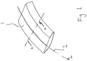
- Fig. 1
- shows in a perspective view a section of a carrier intended to be attached to an outer bearing ring of a roller bearing, on which a glass fiber is fixed,
- Fig. 2
- shows the cross section A-A according to
Fig. 1 , - Fig. 3
- shows a perspective view of a glass fiber which is fixed to a carrier similar to
Fig. 2 , - Fig. 4
- shows a front view of a glass fiber which is fixed to a carrier, similar to
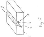
Fig. 3 , - Fig. 5
- shows a perspective view of a glass fiber which is fixed in a groove of a careier,
- Fig. 6
- shows a front view of a glass fiber which is fixed in a groove of a carrier, similar to
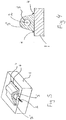
Fig. 5 , - Fig. 7a
- shows the process of fixing a glass fiber in a groove of a carrier in a first, early state,
- Fig. 7b
- shows the process of fixing a glass fiber in a groove of a carrier in a second, later state.
- In
Fig. 1 amachine arrangement 1 is shown being a carrier to be attached to an outer bearing ring of a roller bearing of the machine arrangement. Thecarrier 1 has an outer spherical surface which is to be monitored with respect to strains which act in the machine part. The survey of those strains is carried out by the fiber Bragg grating (FBG) method which is known as such. Reference is made e. g. toUS 6,923,048 B2 where this technology is explained in more detail. - For doing so a
glass fiber 2 is securely fixed on the spherical, i. e. cylindrical outer circumference of thecarrier 1. Theglass fiber 2 has a longitudinal direction L which extends in the circumferential direction of thecarrier 1. - Details concerning the fixation of the
glass fiber 2 at thecarrier 1 can be seen fromFig. 2 . - Here, it can be seen that the
glass fiber 2 is basically the pure glass element - possibly covered only by a reflective coating to ensure proper light conduction within the glass fiber - which is then connected with thecarrier 1 by means ofmetallic material 3. - Here, two different metallic materials are employed:
A first metallic material 3' coats theglass fiber 2 itself. The preferred material is chromium (Cr). - The first metallic material 3' it then connected with a second
metallic material 3". This material is preferably an alloy, preferably from chromium (Cr) and nickel (Ni). - Thus, a material bonding is established between the
glass fiber 2 and themachine part 1 to be monitored. This means, all strains in themachine part 1 are directly transferred into theglass fiber 2. Thus, the precondition is assured for a precise measurement of physical parameters of themachine part 1. - In
Fig. 3 a further embodiment of the invention is shown. Here, theglass fiber 2 is provided with a cladding 3' from a first metallic material being nickel (Ni). This cladding is embedded in a secondmetallic material 3" being a nickel-chromium-alloy. The secondmetallic material 3" is fixed on thecarrier 1 by means of welding orbrazing 4. - In
Fig. 4 a similar solution is shown. Here, theglass fiber 2 is again embedded in a cladding of nickel 3'. This cladding is covered by acoating 3" of a nickel-chromium-alloy. Thiscoating 3" is fixed with thecarrier 1 by means of welding orbrazing 4. - In
Fig. 5 an alternative is shown. Here thecarrier 1 has agroove 5, in which theglass fiber 2 is inserted and securely fixed. For doing so, theglass fiber 2 is cladded with a cover 3' from nickel. Then, the coveredglass fiber 2 is fixed on thecarrier 1 by a nickel-chromium-alloy 3 "which fills up thegroove 5. - A similar solution is shown in
Fig. 6 . Here, thecarrier 1 again has agroove 5 in which theglass fiber 2 is inserted. Theglass fiber 2 is embedded in a nickel cladding 3'. The cladding 3' is embedded by a nickel-chromium-alloy 3". The fixation of the coating of nickel-chromium-alloy 3" is fixed in thegroove 5 by means of welding orbrazing 4. - In
Fig. 7a and Fig. 7b a process is depicted by which a fixation as shown inFig. 6 can be realized. Here, acontainer 7 is arranged at thecarrier 1 when the embedded glass fiber 2 (coated again by a nickel layer 3' and a layer form a nickel-chromium-alloy 3") is arranged in agroove 5 in thecarrier 1. Thecontainer 7 is filled with braze paste 6. This is shown inFig. 7a . - Heating elements 8 being inductive heaters are arranged near the
container 7. Due to the heat produced by the inductive heaters 8 the braze paste 6 melts and forms thebrazing 4 which is shown inFig. 7b . Afterwards, thecontainer 7 is removed. - The proposed connection technology can be used to fix a
glass fiber 2 firmly between two points on thecarrier 1 to use the fiber Bragg grating (FBG) method for measurement of specific data. - For the cladding of the
glass fiber 2 itself, pure material - specifically nickel (Ni) or chromium (Cr) - is preferred. This gives a very dense and defect free coating. - For the outer coating a selection can be made from suitable alloys between nickel (Ni) and chromium (Cr) with or without additional elements such as B, Fe, Mn, Si, Ti, which can be selected to obtain a harder or more ductile coating and/or to reduce the melting temperature for the coating or later brazing or welding to be applied.
- Beside pure nickel also nickel can be used which is alloyed with a maximum of 2 weight-% titan (Ti), 1 weight-% silizium (Si) or a nickel-alloy with a maximum of 3.5 weight-% boron (B), 4.5 weight-% silizium (Si), between 5 and 7 weight-% chromium (Cr) and about 4 weight-% ferrum (Fe).
- For the
outer coating 3" pure chromium (Cr) can be employed but also chromium alloyed with a maximum of 20 to 60 weight-% nickel (Ni). The outer coating has preferably between 0.2 to 0.5 mm wall thickness in order to enable microlaser welding or brazing, - Here, a nickel-chromium-alloy is preferred with 20 to 80 weight-% nickel (Ni) and a balance of chromium (Cr). Also, an alloy has been found suitable with 20 to 70 weight-% nickel (Ni), 1 to 5 weight-% mangan (Mn), a maximum of 1 weight-% silizium (Si) and a balance of chromium (Cr). Also the addition of copper (Cu) can be beneficial.
- In
Fig. 8 a glass fiber withcore 82, suitably working up to 1000 degrees Centigrade, comprising an in-core Bragg grating 83 has been prepared to be vacuum brazed to a stainless steel carrier. Theglass fiber 82 typically comprises acopper coating 84 which outside theattachment area 89 is protected by a thin layer of electroplatedNi 86 during activation. A thinchemical Ni layer 87 is then added to make the bare fiber part electrically conducting and finally an electroplated Ni-layer 88, about 20 micrometers thick is added. Thelength 89 along which theglass fiber 82 is to be mounted to a carrier will be bare before the Ni layers 87, 88 are added and will comprise one or more in-core Bragg gratings 83. - In
Fig. 9 acarrier 91, suitably of 430 stainless steel, is mounted on anouter ring 99 of a bearing. This is of course one of many different location on a bearing that the carrier can be mounted. The carrier described can suitably be mounted on any hardened steel, especially hardened bearing steel. Thecarrier 91 can suitably be in the range of 25 millimeter long in the direction of a mountedoptical fiber carrier 91 is thin so that theoptical fiber 92 is as close as possible to the part it is supposed to measure as the optical fiber is on one side and the machine part on the other side. Thecarrier 91 suitable comprises a groove with a diameter/depth in the range of 0.3 millimeter for a nickel coatedoptical fiber 92. A preparedoptical fiber 92, suitably of the kind according toFig. 8 , is put in the groove and a filling material 94 is added between the nickel coated fibers and thestainless steel carrier 91. The filling material can suitably be brazing alloy Cusin-1 ABA paste. Theoptical fiber 92 is then embedded into thecarrier 91 by brazing, suitably vacuum brazing. After theoptical fiber 92 has been embedded into or onto thecarrier 91, thecarrier 91 is then attached to a machine part which is to be measured as to for example temperature and/or strain. The attachment of thecarrier 91 to, as in this example, an outer bearing ring, is according to this embodiment done by pulse arc welding, such as micro TIG welding in an Argon atmosphere. Theoptical fiber 92 will then have a stiff connection with the machine part it is meant to measure. -
- 1
- Machine arrangement (carrier)
- 2
- Glass fiber
- 3
- Metallic material
- 3'
- First metallic material
- 3"
- Second metallic material
- 4
- Welding / Brazing
- 5
- Groove
- 6
- Braze paste
- 7
- Container
- 8
- Heating element (induction heating element)
- 82
- Glass fiber with core, suitably working up to 1000 degrees C
- 83
- In-core Bragg grating
- 84
- Copper, Cu, coating of fiber
- 86
- Thin electroplated Ni to protect the Cu during activation
- 87
- Thin chemical Ni layer to make the bare fiber part electrically conducting
- 88
- Final electroplated Ni-layer, about 20 micrometers thick
- 89
- Carrier mounting area
- 91
- Carrier, suitably 430 stainless steel
- 92
- Optical fiber, suitable working up to a 1000 degrees C
- 94
- Filling material, suitably brazing alloy Cusin-1 ABA paste
- 98
- Pulse Arc welding, micro TIG (Tungsten Inert Gas) in Argon atmosphere
- L
- Longitudinal axis
Claims (4)
- Machine arrangement, comprising a machine part to be monitored (99) and comprising at least one carrier (1 ; 91) arranged on the machine part to be monitored (99), wherein a glass fiber (2 ; 92) is connected with the carrier (1 ; 91), wherein the connection between the glass fiber and the carrier (1 ; 91) is established by a metallic material (3' ; 3") which metallic material is connected by material bonding with the carrier (1 ; 91) as well as with the glass fiber,
characterized in that
the carrier comprises a groove in which the glass fiber is arranged, wherein a filling consisting of a brazing alloy (94) is arranged between the glass fiber and the carrier, wherein the glass fiber is embedded into the carrier by brazing, wherein the carrier is attached to the machine part to be monitored (99) by means of pulse arc welding. - Machine arrangement according to claim 1, characterized in that the glass fiber is encased by a reflective cover material.
- Machine arrangement according to claim 1 or 2, characterized in that the carrier is made of stainless steel.
- Machine arrangement according to any one of claims 1 to 3, characterized in that the carrier is connected by means of pulse arc welding to a machine part made of hardened steel.
Priority Applications (1)
| Application Number | Priority Date | Filing Date | Title |
|---|---|---|---|
| EP13728415.4A EP2861953B1 (en) | 2012-06-14 | 2013-06-14 | Machine arrangement |
Applications Claiming Priority (3)
| Application Number | Priority Date | Filing Date | Title |
|---|---|---|---|
| EP2012061347 | 2012-06-14 | ||
| EP13728415.4A EP2861953B1 (en) | 2012-06-14 | 2013-06-14 | Machine arrangement |
| PCT/EP2013/062358 WO2013186354A1 (en) | 2012-06-14 | 2013-06-14 | Machine arrangement |
Publications (2)
| Publication Number | Publication Date |
|---|---|
| EP2861953A1 EP2861953A1 (en) | 2015-04-22 |
| EP2861953B1 true EP2861953B1 (en) | 2018-09-19 |
Family
ID=52672131
Family Applications (1)
| Application Number | Title | Priority Date | Filing Date |
|---|---|---|---|
| EP13728415.4A Not-in-force EP2861953B1 (en) | 2012-06-14 | 2013-06-14 | Machine arrangement |
Country Status (1)
| Country | Link |
|---|---|
| EP (1) | EP2861953B1 (en) |
Families Citing this family (1)
| Publication number | Priority date | Publication date | Assignee | Title |
|---|---|---|---|---|
| GB2576167A (en) * | 2018-08-07 | 2020-02-12 | S360 Group B V | Sensing assembly for bearing and mounting method |
-
2013
- 2013-06-14 EP EP13728415.4A patent/EP2861953B1/en not_active Not-in-force
Non-Patent Citations (1)
| Title |
|---|
| None * |
Also Published As
| Publication number | Publication date |
|---|---|
| EP2861953A1 (en) | 2015-04-22 |
Similar Documents
| Publication | Publication Date | Title |
|---|---|---|
| US9897514B2 (en) | Machine arrangement | |
| EP3030872B1 (en) | High temperature probe | |
| EP2748571B1 (en) | Temperature sensing assembly for measuring temperature of a surface of a structure | |
| CA2750905C (en) | Method for monitoring deformation of well equipment | |
| KR101181255B1 (en) | Integration of an optical waveguide of a sensor into a component | |
| Kim et al. | 3D Printing of a miniature turbine blade model with an embedded fibre Bragg grating sensor for high-temperature monitoring | |
| CN105806504A (en) | High-temperature-resistant cheap metal armored thermocouple and manufacturing method thereof | |
| KR20160065864A (en) | Method for producing a metal-ceramic soldered connection | |
| US9746387B2 (en) | Machine arrangement | |
| JPH07508832A (en) | optical temperature probe | |
| US10119205B2 (en) | Composite reinforcing insert and manufacturing method | |
| Grandal et al. | Analysis of fiber optic sensor embedded in metals by automatic and manual TIG welding | |
| JPWO2016068242A1 (en) | Ceramic heater and manufacturing method thereof | |
| EP2861953A1 (en) | Machine arrangement | |
| JP2008260046A (en) | Continuous casting mold | |
| EP2861952A1 (en) | Machine arrangement | |
| Arévalo et al. | Embedding of fiber optic sensors in metal parts by laser welding and additive manufacturing: A review | |
| Sandlin et al. | Use of brazing technique for manufacturing of high temperature fibre optical temperature and displacement transducer | |
| EP4038425A1 (en) | Metal-coated optical fiber and a method of fabricating thereof | |
| EP2861954B1 (en) | Machine arrangement | |
| Grandal et al. | Laser brazing metallic embedding technique for fiber optic sensors | |
| KR20250164497A (en) | Method for embedding an optical fiber sensor in a metal structure and a metal structure in which an optical fiber sensor is embedded thereby | |
| WO2002003483A1 (en) | Battery case feedthrough | |
| US20250205835A1 (en) | Method for manufacturing a heat exchanger by brazing a temperature probe, corresponding heat exchanger and temperature probe | |
| Grandal et al. | Fibre optic sensor embedded into metals using low cost TIG welding and high precision laser brazing |
Legal Events
| Date | Code | Title | Description |
|---|---|---|---|
| PUAI | Public reference made under article 153(3) epc to a published international application that has entered the european phase |
Free format text: ORIGINAL CODE: 0009012 |
|
| 17P | Request for examination filed |
Effective date: 20141212 |
|
| AK | Designated contracting states |
Kind code of ref document: A1 Designated state(s): AL AT BE BG CH CY CZ DE DK EE ES FI FR GB GR HR HU IE IS IT LI LT LU LV MC MK MT NL NO PL PT RO RS SE SI SK SM TR |
|
| AX | Request for extension of the european patent |
Extension state: BA ME |
|
| DAX | Request for extension of the european patent (deleted) | ||
| GRAP | Despatch of communication of intention to grant a patent |
Free format text: ORIGINAL CODE: EPIDOSNIGR1 |
|
| STAA | Information on the status of an ep patent application or granted ep patent |
Free format text: STATUS: GRANT OF PATENT IS INTENDED |
|
| INTG | Intention to grant announced |
Effective date: 20180410 |
|
| GRAS | Grant fee paid |
Free format text: ORIGINAL CODE: EPIDOSNIGR3 |
|
| GRAA | (expected) grant |
Free format text: ORIGINAL CODE: 0009210 |
|
| STAA | Information on the status of an ep patent application or granted ep patent |
Free format text: STATUS: THE PATENT HAS BEEN GRANTED |
|
| AK | Designated contracting states |
Kind code of ref document: B1 Designated state(s): AL AT BE BG CH CY CZ DE DK EE ES FI FR GB GR HR HU IE IS IT LI LT LU LV MC MK MT NL NO PL PT RO RS SE SI SK SM TR |
|
| REG | Reference to a national code |
Ref country code: GB Ref legal event code: FG4D |
|
| REG | Reference to a national code |
Ref country code: CH Ref legal event code: EP |
|
| REG | Reference to a national code |
Ref country code: AT Ref legal event code: REF Ref document number: 1043809 Country of ref document: AT Kind code of ref document: T Effective date: 20181015 |
|
| REG | Reference to a national code |
Ref country code: IE Ref legal event code: FG4D |
|
| REG | Reference to a national code |
Ref country code: DE Ref legal event code: R096 Ref document number: 602013043867 Country of ref document: DE |
|
| REG | Reference to a national code |
Ref country code: NL Ref legal event code: MP Effective date: 20180919 |
|
| PG25 | Lapsed in a contracting state [announced via postgrant information from national office to epo] |
Ref country code: NO Free format text: LAPSE BECAUSE OF FAILURE TO SUBMIT A TRANSLATION OF THE DESCRIPTION OR TO PAY THE FEE WITHIN THE PRESCRIBED TIME-LIMIT Effective date: 20181219 Ref country code: BG Free format text: LAPSE BECAUSE OF FAILURE TO SUBMIT A TRANSLATION OF THE DESCRIPTION OR TO PAY THE FEE WITHIN THE PRESCRIBED TIME-LIMIT Effective date: 20181219 Ref country code: GR Free format text: LAPSE BECAUSE OF FAILURE TO SUBMIT A TRANSLATION OF THE DESCRIPTION OR TO PAY THE FEE WITHIN THE PRESCRIBED TIME-LIMIT Effective date: 20181220 Ref country code: LT Free format text: LAPSE BECAUSE OF FAILURE TO SUBMIT A TRANSLATION OF THE DESCRIPTION OR TO PAY THE FEE WITHIN THE PRESCRIBED TIME-LIMIT Effective date: 20180919 Ref country code: SE Free format text: LAPSE BECAUSE OF FAILURE TO SUBMIT A TRANSLATION OF THE DESCRIPTION OR TO PAY THE FEE WITHIN THE PRESCRIBED TIME-LIMIT Effective date: 20180919 Ref country code: RS Free format text: LAPSE BECAUSE OF FAILURE TO SUBMIT A TRANSLATION OF THE DESCRIPTION OR TO PAY THE FEE WITHIN THE PRESCRIBED TIME-LIMIT Effective date: 20180919 Ref country code: FI Free format text: LAPSE BECAUSE OF FAILURE TO SUBMIT A TRANSLATION OF THE DESCRIPTION OR TO PAY THE FEE WITHIN THE PRESCRIBED TIME-LIMIT Effective date: 20180919 |
|
| REG | Reference to a national code |
Ref country code: LT Ref legal event code: MG4D |
|
| PG25 | Lapsed in a contracting state [announced via postgrant information from national office to epo] |
Ref country code: AL Free format text: LAPSE BECAUSE OF FAILURE TO SUBMIT A TRANSLATION OF THE DESCRIPTION OR TO PAY THE FEE WITHIN THE PRESCRIBED TIME-LIMIT Effective date: 20180919 Ref country code: LV Free format text: LAPSE BECAUSE OF FAILURE TO SUBMIT A TRANSLATION OF THE DESCRIPTION OR TO PAY THE FEE WITHIN THE PRESCRIBED TIME-LIMIT Effective date: 20180919 Ref country code: HR Free format text: LAPSE BECAUSE OF FAILURE TO SUBMIT A TRANSLATION OF THE DESCRIPTION OR TO PAY THE FEE WITHIN THE PRESCRIBED TIME-LIMIT Effective date: 20180919 |
|
| REG | Reference to a national code |
Ref country code: AT Ref legal event code: MK05 Ref document number: 1043809 Country of ref document: AT Kind code of ref document: T Effective date: 20180919 |
|
| PG25 | Lapsed in a contracting state [announced via postgrant information from national office to epo] |
Ref country code: NL Free format text: LAPSE BECAUSE OF FAILURE TO SUBMIT A TRANSLATION OF THE DESCRIPTION OR TO PAY THE FEE WITHIN THE PRESCRIBED TIME-LIMIT Effective date: 20180919 Ref country code: PL Free format text: LAPSE BECAUSE OF FAILURE TO SUBMIT A TRANSLATION OF THE DESCRIPTION OR TO PAY THE FEE WITHIN THE PRESCRIBED TIME-LIMIT Effective date: 20180919 Ref country code: IS Free format text: LAPSE BECAUSE OF FAILURE TO SUBMIT A TRANSLATION OF THE DESCRIPTION OR TO PAY THE FEE WITHIN THE PRESCRIBED TIME-LIMIT Effective date: 20190119 Ref country code: AT Free format text: LAPSE BECAUSE OF FAILURE TO SUBMIT A TRANSLATION OF THE DESCRIPTION OR TO PAY THE FEE WITHIN THE PRESCRIBED TIME-LIMIT Effective date: 20180919 Ref country code: EE Free format text: LAPSE BECAUSE OF FAILURE TO SUBMIT A TRANSLATION OF THE DESCRIPTION OR TO PAY THE FEE WITHIN THE PRESCRIBED TIME-LIMIT Effective date: 20180919 Ref country code: CZ Free format text: LAPSE BECAUSE OF FAILURE TO SUBMIT A TRANSLATION OF THE DESCRIPTION OR TO PAY THE FEE WITHIN THE PRESCRIBED TIME-LIMIT Effective date: 20180919 Ref country code: IT Free format text: LAPSE BECAUSE OF FAILURE TO SUBMIT A TRANSLATION OF THE DESCRIPTION OR TO PAY THE FEE WITHIN THE PRESCRIBED TIME-LIMIT Effective date: 20180919 Ref country code: RO Free format text: LAPSE BECAUSE OF FAILURE TO SUBMIT A TRANSLATION OF THE DESCRIPTION OR TO PAY THE FEE WITHIN THE PRESCRIBED TIME-LIMIT Effective date: 20180919 Ref country code: ES Free format text: LAPSE BECAUSE OF FAILURE TO SUBMIT A TRANSLATION OF THE DESCRIPTION OR TO PAY THE FEE WITHIN THE PRESCRIBED TIME-LIMIT Effective date: 20180919 |
|
| PG25 | Lapsed in a contracting state [announced via postgrant information from national office to epo] |
Ref country code: SK Free format text: LAPSE BECAUSE OF FAILURE TO SUBMIT A TRANSLATION OF THE DESCRIPTION OR TO PAY THE FEE WITHIN THE PRESCRIBED TIME-LIMIT Effective date: 20180919 Ref country code: PT Free format text: LAPSE BECAUSE OF FAILURE TO SUBMIT A TRANSLATION OF THE DESCRIPTION OR TO PAY THE FEE WITHIN THE PRESCRIBED TIME-LIMIT Effective date: 20190119 Ref country code: SM Free format text: LAPSE BECAUSE OF FAILURE TO SUBMIT A TRANSLATION OF THE DESCRIPTION OR TO PAY THE FEE WITHIN THE PRESCRIBED TIME-LIMIT Effective date: 20180919 |
|
| REG | Reference to a national code |
Ref country code: DE Ref legal event code: R097 Ref document number: 602013043867 Country of ref document: DE |
|
| PLBE | No opposition filed within time limit |
Free format text: ORIGINAL CODE: 0009261 |
|
| STAA | Information on the status of an ep patent application or granted ep patent |
Free format text: STATUS: NO OPPOSITION FILED WITHIN TIME LIMIT |
|
| PG25 | Lapsed in a contracting state [announced via postgrant information from national office to epo] |
Ref country code: DK Free format text: LAPSE BECAUSE OF FAILURE TO SUBMIT A TRANSLATION OF THE DESCRIPTION OR TO PAY THE FEE WITHIN THE PRESCRIBED TIME-LIMIT Effective date: 20180919 |
|
| 26N | No opposition filed |
Effective date: 20190620 |
|
| PG25 | Lapsed in a contracting state [announced via postgrant information from national office to epo] |
Ref country code: SI Free format text: LAPSE BECAUSE OF FAILURE TO SUBMIT A TRANSLATION OF THE DESCRIPTION OR TO PAY THE FEE WITHIN THE PRESCRIBED TIME-LIMIT Effective date: 20180919 |
|
| PGFP | Annual fee paid to national office [announced via postgrant information from national office to epo] |
Ref country code: DE Payment date: 20190830 Year of fee payment: 7 |
|
| PG25 | Lapsed in a contracting state [announced via postgrant information from national office to epo] |
Ref country code: MC Free format text: LAPSE BECAUSE OF FAILURE TO SUBMIT A TRANSLATION OF THE DESCRIPTION OR TO PAY THE FEE WITHIN THE PRESCRIBED TIME-LIMIT Effective date: 20180919 |
|
| REG | Reference to a national code |
Ref country code: CH Ref legal event code: PL |
|
| GBPC | Gb: european patent ceased through non-payment of renewal fee |
Effective date: 20190614 |
|
| REG | Reference to a national code |
Ref country code: BE Ref legal event code: MM Effective date: 20190630 |
|
| PG25 | Lapsed in a contracting state [announced via postgrant information from national office to epo] |
Ref country code: TR Free format text: LAPSE BECAUSE OF FAILURE TO SUBMIT A TRANSLATION OF THE DESCRIPTION OR TO PAY THE FEE WITHIN THE PRESCRIBED TIME-LIMIT Effective date: 20180919 |
|
| PG25 | Lapsed in a contracting state [announced via postgrant information from national office to epo] |
Ref country code: GB Free format text: LAPSE BECAUSE OF NON-PAYMENT OF DUE FEES Effective date: 20190614 Ref country code: IE Free format text: LAPSE BECAUSE OF NON-PAYMENT OF DUE FEES Effective date: 20190614 |
|
| PG25 | Lapsed in a contracting state [announced via postgrant information from national office to epo] |
Ref country code: CH Free format text: LAPSE BECAUSE OF NON-PAYMENT OF DUE FEES Effective date: 20190630 Ref country code: LU Free format text: LAPSE BECAUSE OF NON-PAYMENT OF DUE FEES Effective date: 20190614 Ref country code: BE Free format text: LAPSE BECAUSE OF NON-PAYMENT OF DUE FEES Effective date: 20190630 Ref country code: LI Free format text: LAPSE BECAUSE OF NON-PAYMENT OF DUE FEES Effective date: 20190630 |
|
| PG25 | Lapsed in a contracting state [announced via postgrant information from national office to epo] |
Ref country code: FR Free format text: LAPSE BECAUSE OF NON-PAYMENT OF DUE FEES Effective date: 20190630 |
|
| REG | Reference to a national code |
Ref country code: DE Ref legal event code: R119 Ref document number: 602013043867 Country of ref document: DE |
|
| PG25 | Lapsed in a contracting state [announced via postgrant information from national office to epo] |
Ref country code: CY Free format text: LAPSE BECAUSE OF FAILURE TO SUBMIT A TRANSLATION OF THE DESCRIPTION OR TO PAY THE FEE WITHIN THE PRESCRIBED TIME-LIMIT Effective date: 20180919 Ref country code: DE Free format text: LAPSE BECAUSE OF NON-PAYMENT OF DUE FEES Effective date: 20210101 |
|
| PG25 | Lapsed in a contracting state [announced via postgrant information from national office to epo] |
Ref country code: MT Free format text: LAPSE BECAUSE OF FAILURE TO SUBMIT A TRANSLATION OF THE DESCRIPTION OR TO PAY THE FEE WITHIN THE PRESCRIBED TIME-LIMIT Effective date: 20180919 Ref country code: HU Free format text: LAPSE BECAUSE OF FAILURE TO SUBMIT A TRANSLATION OF THE DESCRIPTION OR TO PAY THE FEE WITHIN THE PRESCRIBED TIME-LIMIT; INVALID AB INITIO Effective date: 20130614 |
|
| PG25 | Lapsed in a contracting state [announced via postgrant information from national office to epo] |
Ref country code: MK Free format text: LAPSE BECAUSE OF FAILURE TO SUBMIT A TRANSLATION OF THE DESCRIPTION OR TO PAY THE FEE WITHIN THE PRESCRIBED TIME-LIMIT Effective date: 20180919 |