EP2860797A1 - Nonaqueous electrolyte secondary battery - Google Patents
Nonaqueous electrolyte secondary battery Download PDFInfo
- Publication number
- EP2860797A1 EP2860797A1 EP20140188144 EP14188144A EP2860797A1 EP 2860797 A1 EP2860797 A1 EP 2860797A1 EP 20140188144 EP20140188144 EP 20140188144 EP 14188144 A EP14188144 A EP 14188144A EP 2860797 A1 EP2860797 A1 EP 2860797A1
- Authority
- EP
- European Patent Office
- Prior art keywords
- amount
- positive electrode
- additive
- negative electrode
- active material
- Prior art date
- Legal status (The legal status is an assumption and is not a legal conclusion. Google has not performed a legal analysis and makes no representation as to the accuracy of the status listed.)
- Withdrawn
Links
- 239000011255 nonaqueous electrolyte Substances 0.000 title claims abstract description 16
- 239000000654 additive Substances 0.000 claims abstract description 121
- 230000000996 additive effect Effects 0.000 claims abstract description 120
- 239000003792 electrolyte Substances 0.000 claims abstract description 63
- 238000007599 discharging Methods 0.000 claims abstract description 40
- 239000007774 positive electrode material Substances 0.000 claims description 20
- 239000007773 negative electrode material Substances 0.000 claims description 15
- 239000003795 chemical substances by application Substances 0.000 claims description 10
- 238000010030 laminating Methods 0.000 claims description 4
- 229910052799 carbon Inorganic materials 0.000 abstract description 4
- 239000010410 layer Substances 0.000 description 41
- 239000011149 active material Substances 0.000 description 39
- 239000011248 coating agent Substances 0.000 description 25
- 238000000576 coating method Methods 0.000 description 25
- 239000002245 particle Substances 0.000 description 17
- NINIDFKCEFEMDL-UHFFFAOYSA-N Sulfur Chemical compound [S] NINIDFKCEFEMDL-UHFFFAOYSA-N 0.000 description 14
- 239000005001 laminate film Substances 0.000 description 14
- 229910052717 sulfur Inorganic materials 0.000 description 14
- 239000011593 sulfur Substances 0.000 description 14
- -1 sultone compound Chemical class 0.000 description 14
- 230000014759 maintenance of location Effects 0.000 description 11
- 238000003860 storage Methods 0.000 description 10
- 230000002829 reductive effect Effects 0.000 description 9
- 239000000463 material Substances 0.000 description 8
- 230000015572 biosynthetic process Effects 0.000 description 7
- 238000000034 method Methods 0.000 description 7
- 229920006395 saturated elastomer Polymers 0.000 description 7
- 238000012360 testing method Methods 0.000 description 7
- HBBGRARXTFLTSG-UHFFFAOYSA-N Lithium ion Chemical compound [Li+] HBBGRARXTFLTSG-UHFFFAOYSA-N 0.000 description 6
- 238000010586 diagram Methods 0.000 description 6
- 239000011888 foil Substances 0.000 description 6
- 150000002430 hydrocarbons Chemical group 0.000 description 6
- 238000009616 inductively coupled plasma Methods 0.000 description 6
- 229910001416 lithium ion Inorganic materials 0.000 description 6
- 230000009467 reduction Effects 0.000 description 6
- 238000002798 spectrophotometry method Methods 0.000 description 6
- 229920003002 synthetic resin Polymers 0.000 description 6
- 239000000057 synthetic resin Substances 0.000 description 6
- 239000004743 Polypropylene Substances 0.000 description 5
- 150000002148 esters Chemical class 0.000 description 5
- 229920001155 polypropylene Polymers 0.000 description 5
- 238000001179 sorption measurement Methods 0.000 description 5
- OKTJSMMVPCPJKN-UHFFFAOYSA-N Carbon Chemical compound [C] OKTJSMMVPCPJKN-UHFFFAOYSA-N 0.000 description 4
- 230000008859 change Effects 0.000 description 4
- 150000001875 compounds Chemical class 0.000 description 4
- 238000004519 manufacturing process Methods 0.000 description 4
- 239000012528 membrane Substances 0.000 description 4
- 230000002093 peripheral effect Effects 0.000 description 4
- 239000000243 solution Substances 0.000 description 4
- WHXSMMKQMYFTQS-UHFFFAOYSA-N Lithium Chemical compound [Li] WHXSMMKQMYFTQS-UHFFFAOYSA-N 0.000 description 3
- 239000004698 Polyethylene Substances 0.000 description 3
- 238000004458 analytical method Methods 0.000 description 3
- 239000011230 binding agent Substances 0.000 description 3
- 238000000354 decomposition reaction Methods 0.000 description 3
- 238000003487 electrochemical reaction Methods 0.000 description 3
- 230000006872 improvement Effects 0.000 description 3
- 229910052744 lithium Inorganic materials 0.000 description 3
- 229910003002 lithium salt Inorganic materials 0.000 description 3
- 159000000002 lithium salts Chemical class 0.000 description 3
- 238000012423 maintenance Methods 0.000 description 3
- 238000005259 measurement Methods 0.000 description 3
- 229920000573 polyethylene Polymers 0.000 description 3
- 229920000098 polyolefin Polymers 0.000 description 3
- 238000005070 sampling Methods 0.000 description 3
- 229930195734 saturated hydrocarbon Natural products 0.000 description 3
- 229930195735 unsaturated hydrocarbon Natural products 0.000 description 3
- YEJRWHAVMIAJKC-UHFFFAOYSA-N 4-Butyrolactone Chemical compound O=C1CCCO1 YEJRWHAVMIAJKC-UHFFFAOYSA-N 0.000 description 2
- RYGMFSIKBFXOCR-UHFFFAOYSA-N Copper Chemical compound [Cu] RYGMFSIKBFXOCR-UHFFFAOYSA-N 0.000 description 2
- 239000002000 Electrolyte additive Substances 0.000 description 2
- 241000220317 Rosa Species 0.000 description 2
- 229910052782 aluminium Inorganic materials 0.000 description 2
- XAGFODPZIPBFFR-UHFFFAOYSA-N aluminium Chemical compound [Al] XAGFODPZIPBFFR-UHFFFAOYSA-N 0.000 description 2
- 239000002131 composite material Substances 0.000 description 2
- 239000011889 copper foil Substances 0.000 description 2
- KZTYYGOKRVBIMI-UHFFFAOYSA-N diphenyl sulfone Chemical compound C=1C=CC=CC=1S(=O)(=O)C1=CC=CC=C1 KZTYYGOKRVBIMI-UHFFFAOYSA-N 0.000 description 2
- 238000005516 engineering process Methods 0.000 description 2
- 229910002804 graphite Inorganic materials 0.000 description 2
- 239000010439 graphite Substances 0.000 description 2
- 230000002401 inhibitory effect Effects 0.000 description 2
- 238000004255 ion exchange chromatography Methods 0.000 description 2
- 229910000625 lithium cobalt oxide Inorganic materials 0.000 description 2
- 229910002102 lithium manganese oxide Inorganic materials 0.000 description 2
- BFZPBUKRYWOWDV-UHFFFAOYSA-N lithium;oxido(oxo)cobalt Chemical compound [Li+].[O-][Co]=O BFZPBUKRYWOWDV-UHFFFAOYSA-N 0.000 description 2
- VLXXBCXTUVRROQ-UHFFFAOYSA-N lithium;oxido-oxo-(oxomanganiooxy)manganese Chemical compound [Li+].[O-][Mn](=O)O[Mn]=O VLXXBCXTUVRROQ-UHFFFAOYSA-N 0.000 description 2
- 230000007246 mechanism Effects 0.000 description 2
- 229910052751 metal Inorganic materials 0.000 description 2
- 239000002184 metal Substances 0.000 description 2
- 239000012982 microporous membrane Substances 0.000 description 2
- 239000003960 organic solvent Substances 0.000 description 2
- 229920000139 polyethylene terephthalate Polymers 0.000 description 2
- 239000005020 polyethylene terephthalate Substances 0.000 description 2
- 239000011253 protective coating Substances 0.000 description 2
- 239000011241 protective layer Substances 0.000 description 2
- 239000000376 reactant Substances 0.000 description 2
- 230000001105 regulatory effect Effects 0.000 description 2
- 229920005989 resin Polymers 0.000 description 2
- 239000011347 resin Substances 0.000 description 2
- 230000004044 response Effects 0.000 description 2
- 230000000630 rising effect Effects 0.000 description 2
- HHVIBTZHLRERCL-UHFFFAOYSA-N sulfonyldimethane Chemical compound CS(C)(=O)=O HHVIBTZHLRERCL-UHFFFAOYSA-N 0.000 description 2
- 150000008053 sultones Chemical class 0.000 description 2
- FSSPGSAQUIYDCN-UHFFFAOYSA-N 1,3-Propane sultone Chemical compound O=S1(=O)CCCO1 FSSPGSAQUIYDCN-UHFFFAOYSA-N 0.000 description 1
- HNSDLXPSAYFUHK-UHFFFAOYSA-N 1,4-bis(2-ethylhexyl) sulfosuccinate Chemical compound CCCCC(CC)COC(=O)CC(S(O)(=O)=O)C(=O)OCC(CC)CCCC HNSDLXPSAYFUHK-UHFFFAOYSA-N 0.000 description 1
- BJEWLOAZFAGNPE-UHFFFAOYSA-N 1-ethenylsulfonylethane Chemical compound CCS(=O)(=O)C=C BJEWLOAZFAGNPE-UHFFFAOYSA-N 0.000 description 1
- MBDUIEKYVPVZJH-UHFFFAOYSA-N 1-ethylsulfonylethane Chemical compound CCS(=O)(=O)CC MBDUIEKYVPVZJH-UHFFFAOYSA-N 0.000 description 1
- YBJCDTIWNDBNTM-UHFFFAOYSA-N 1-methylsulfonylethane Chemical compound CCS(C)(=O)=O YBJCDTIWNDBNTM-UHFFFAOYSA-N 0.000 description 1
- WUIJTQZXUURFQU-UHFFFAOYSA-N 1-methylsulfonylethene Chemical compound CS(=O)(=O)C=C WUIJTQZXUURFQU-UHFFFAOYSA-N 0.000 description 1
- 229910000838 Al alloy Inorganic materials 0.000 description 1
- 238000004438 BET method Methods 0.000 description 1
- OIFBSDVPJOWBCH-UHFFFAOYSA-N Diethyl carbonate Chemical compound CCOC(=O)OCC OIFBSDVPJOWBCH-UHFFFAOYSA-N 0.000 description 1
- 239000005977 Ethylene Substances 0.000 description 1
- KMTRUDSVKNLOMY-UHFFFAOYSA-N Ethylene carbonate Chemical compound O=C1OCCO1 KMTRUDSVKNLOMY-UHFFFAOYSA-N 0.000 description 1
- XEEYBQQBJWHFJM-UHFFFAOYSA-N Iron Chemical compound [Fe] XEEYBQQBJWHFJM-UHFFFAOYSA-N 0.000 description 1
- 229910001290 LiPF6 Inorganic materials 0.000 description 1
- PXHVJJICTQNCMI-UHFFFAOYSA-N Nickel Chemical compound [Ni] PXHVJJICTQNCMI-UHFFFAOYSA-N 0.000 description 1
- 238000004833 X-ray photoelectron spectroscopy Methods 0.000 description 1
- 239000006230 acetylene black Substances 0.000 description 1
- 230000009471 action Effects 0.000 description 1
- XXROGKLTLUQVRX-UHFFFAOYSA-N allyl alcohol Chemical compound OCC=C XXROGKLTLUQVRX-UHFFFAOYSA-N 0.000 description 1
- 229910003481 amorphous carbon Inorganic materials 0.000 description 1
- 125000003118 aryl group Chemical group 0.000 description 1
- 230000033228 biological regulation Effects 0.000 description 1
- 238000004364 calculation method Methods 0.000 description 1
- 239000006229 carbon black Substances 0.000 description 1
- 239000003575 carbonaceous material Substances 0.000 description 1
- 238000002485 combustion reaction Methods 0.000 description 1
- 230000000052 comparative effect Effects 0.000 description 1
- 239000000470 constituent Substances 0.000 description 1
- 125000004122 cyclic group Chemical group 0.000 description 1
- 230000003247 decreasing effect Effects 0.000 description 1
- 230000002950 deficient Effects 0.000 description 1
- 238000013461 design Methods 0.000 description 1
- 238000010790 dilution Methods 0.000 description 1
- 239000012895 dilution Substances 0.000 description 1
- IEJIGPNLZYLLBP-UHFFFAOYSA-N dimethyl carbonate Chemical compound COC(=O)OC IEJIGPNLZYLLBP-UHFFFAOYSA-N 0.000 description 1
- AFOSIXZFDONLBT-UHFFFAOYSA-N divinyl sulfone Chemical compound C=CS(=O)(=O)C=C AFOSIXZFDONLBT-UHFFFAOYSA-N 0.000 description 1
- 230000000694 effects Effects 0.000 description 1
- UJTPZISIAWDGFF-UHFFFAOYSA-N ethenylsulfonylbenzene Chemical compound C=CS(=O)(=O)C1=CC=CC=C1 UJTPZISIAWDGFF-UHFFFAOYSA-N 0.000 description 1
- XDRMBCMMABGNMM-UHFFFAOYSA-N ethyl benzenesulfonate Chemical compound CCOS(=O)(=O)C1=CC=CC=C1 XDRMBCMMABGNMM-UHFFFAOYSA-N 0.000 description 1
- MWFJXRUUPWIALU-UHFFFAOYSA-N ethyl ethenesulfonate Chemical compound CCOS(=O)(=O)C=C MWFJXRUUPWIALU-UHFFFAOYSA-N 0.000 description 1
- JBTWLSYIZRCDFO-UHFFFAOYSA-N ethyl methyl carbonate Chemical compound CCOC(=O)OC JBTWLSYIZRCDFO-UHFFFAOYSA-N 0.000 description 1
- 230000006870 function Effects 0.000 description 1
- 239000006232 furnace black Substances 0.000 description 1
- 239000011245 gel electrolyte Substances 0.000 description 1
- 229910021469 graphitizable carbon Inorganic materials 0.000 description 1
- 238000002347 injection Methods 0.000 description 1
- 239000007924 injection Substances 0.000 description 1
- 230000003993 interaction Effects 0.000 description 1
- 238000009830 intercalation Methods 0.000 description 1
- 239000007788 liquid Substances 0.000 description 1
- 239000006193 liquid solution Substances 0.000 description 1
- 229910021445 lithium manganese complex oxide Inorganic materials 0.000 description 1
- 229910001496 lithium tetrafluoroborate Inorganic materials 0.000 description 1
- VROAXDSNYPAOBJ-UHFFFAOYSA-N lithium;oxido(oxo)nickel Chemical compound [Li+].[O-][Ni]=O VROAXDSNYPAOBJ-UHFFFAOYSA-N 0.000 description 1
- CZXGXYBOQYQXQD-UHFFFAOYSA-N methyl benzenesulfonate Chemical compound COS(=O)(=O)C1=CC=CC=C1 CZXGXYBOQYQXQD-UHFFFAOYSA-N 0.000 description 1
- YLJRCXSSKLWCDE-UHFFFAOYSA-N methyl ethanesulfonate Chemical compound CCS(=O)(=O)OC YLJRCXSSKLWCDE-UHFFFAOYSA-N 0.000 description 1
- OIGSXRLVIQGTAV-UHFFFAOYSA-N methyl ethenesulfonate Chemical compound COS(=O)(=O)C=C OIGSXRLVIQGTAV-UHFFFAOYSA-N 0.000 description 1
- MBABOKRGFJTBAE-UHFFFAOYSA-N methyl methanesulfonate Chemical compound COS(C)(=O)=O MBABOKRGFJTBAE-UHFFFAOYSA-N 0.000 description 1
- 238000012986 modification Methods 0.000 description 1
- 230000004048 modification Effects 0.000 description 1
- 229910021470 non-graphitizable carbon Inorganic materials 0.000 description 1
- MHYFEEDKONKGEB-UHFFFAOYSA-N oxathiane 2,2-dioxide Chemical compound O=S1(=O)CCCCO1 MHYFEEDKONKGEB-UHFFFAOYSA-N 0.000 description 1
- LQAVWYMTUMSFBE-UHFFFAOYSA-N pent-4-en-1-ol Chemical compound OCCCC=C LQAVWYMTUMSFBE-UHFFFAOYSA-N 0.000 description 1
- 230000000704 physical effect Effects 0.000 description 1
- RUOJZAUFBMNUDX-UHFFFAOYSA-N propylene carbonate Chemical compound CC1COC(=O)O1 RUOJZAUFBMNUDX-UHFFFAOYSA-N 0.000 description 1
- 230000009993 protective function Effects 0.000 description 1
- 239000007784 solid electrolyte Substances 0.000 description 1
- 239000002904 solvent Substances 0.000 description 1
- 239000010935 stainless steel Substances 0.000 description 1
- 229910001220 stainless steel Inorganic materials 0.000 description 1
- HXJUTPCZVOIRIF-UHFFFAOYSA-N sulfolane Chemical compound O=S1(=O)CCCC1 HXJUTPCZVOIRIF-UHFFFAOYSA-N 0.000 description 1
- 150000003459 sulfonic acid esters Chemical class 0.000 description 1
- 150000003464 sulfur compounds Chemical class 0.000 description 1
- 238000003466 welding Methods 0.000 description 1
Images


Classifications
-
- H—ELECTRICITY
- H01—ELECTRIC ELEMENTS
- H01M—PROCESSES OR MEANS, e.g. BATTERIES, FOR THE DIRECT CONVERSION OF CHEMICAL ENERGY INTO ELECTRICAL ENERGY
- H01M10/00—Secondary cells; Manufacture thereof
- H01M10/05—Accumulators with non-aqueous electrolyte
-
- H—ELECTRICITY
- H01—ELECTRIC ELEMENTS
- H01M—PROCESSES OR MEANS, e.g. BATTERIES, FOR THE DIRECT CONVERSION OF CHEMICAL ENERGY INTO ELECTRICAL ENERGY
- H01M10/00—Secondary cells; Manufacture thereof
- H01M10/05—Accumulators with non-aqueous electrolyte
- H01M10/056—Accumulators with non-aqueous electrolyte characterised by the materials used as electrolytes, e.g. mixed inorganic/organic electrolytes
-
- H—ELECTRICITY
- H01—ELECTRIC ELEMENTS
- H01M—PROCESSES OR MEANS, e.g. BATTERIES, FOR THE DIRECT CONVERSION OF CHEMICAL ENERGY INTO ELECTRICAL ENERGY
- H01M10/00—Secondary cells; Manufacture thereof
- H01M10/04—Construction or manufacture in general
- H01M10/049—Processes for forming or storing electrodes in the battery container
-
- H—ELECTRICITY
- H01—ELECTRIC ELEMENTS
- H01M—PROCESSES OR MEANS, e.g. BATTERIES, FOR THE DIRECT CONVERSION OF CHEMICAL ENERGY INTO ELECTRICAL ENERGY
- H01M10/00—Secondary cells; Manufacture thereof
- H01M10/05—Accumulators with non-aqueous electrolyte
- H01M10/052—Li-accumulators
- H01M10/0525—Rocking-chair batteries, i.e. batteries with lithium insertion or intercalation in both electrodes; Lithium-ion batteries
-
- H—ELECTRICITY
- H01—ELECTRIC ELEMENTS
- H01M—PROCESSES OR MEANS, e.g. BATTERIES, FOR THE DIRECT CONVERSION OF CHEMICAL ENERGY INTO ELECTRICAL ENERGY
- H01M10/00—Secondary cells; Manufacture thereof
- H01M10/05—Accumulators with non-aqueous electrolyte
- H01M10/056—Accumulators with non-aqueous electrolyte characterised by the materials used as electrolytes, e.g. mixed inorganic/organic electrolytes
- H01M10/0564—Accumulators with non-aqueous electrolyte characterised by the materials used as electrolytes, e.g. mixed inorganic/organic electrolytes the electrolyte being constituted of organic materials only
- H01M10/0566—Liquid materials
- H01M10/0567—Liquid materials characterised by the additives
-
- H—ELECTRICITY
- H01—ELECTRIC ELEMENTS
- H01M—PROCESSES OR MEANS, e.g. BATTERIES, FOR THE DIRECT CONVERSION OF CHEMICAL ENERGY INTO ELECTRICAL ENERGY
- H01M10/00—Secondary cells; Manufacture thereof
- H01M10/42—Methods or arrangements for servicing or maintenance of secondary cells or secondary half-cells
- H01M10/4235—Safety or regulating additives or arrangements in electrodes, separators or electrolyte
-
- H—ELECTRICITY
- H01—ELECTRIC ELEMENTS
- H01M—PROCESSES OR MEANS, e.g. BATTERIES, FOR THE DIRECT CONVERSION OF CHEMICAL ENERGY INTO ELECTRICAL ENERGY
- H01M10/00—Secondary cells; Manufacture thereof
- H01M10/42—Methods or arrangements for servicing or maintenance of secondary cells or secondary half-cells
- H01M10/44—Methods for charging or discharging
- H01M10/446—Initial charging measures
-
- H—ELECTRICITY
- H01—ELECTRIC ELEMENTS
- H01M—PROCESSES OR MEANS, e.g. BATTERIES, FOR THE DIRECT CONVERSION OF CHEMICAL ENERGY INTO ELECTRICAL ENERGY
- H01M4/00—Electrodes
- H01M4/02—Electrodes composed of, or comprising, active material
- H01M4/13—Electrodes for accumulators with non-aqueous electrolyte, e.g. for lithium-accumulators; Processes of manufacture thereof
-
- H—ELECTRICITY
- H01—ELECTRIC ELEMENTS
- H01M—PROCESSES OR MEANS, e.g. BATTERIES, FOR THE DIRECT CONVERSION OF CHEMICAL ENERGY INTO ELECTRICAL ENERGY
- H01M4/00—Electrodes
- H01M4/02—Electrodes composed of, or comprising, active material
- H01M4/13—Electrodes for accumulators with non-aqueous electrolyte, e.g. for lithium-accumulators; Processes of manufacture thereof
- H01M4/131—Electrodes based on mixed oxides or hydroxides, or on mixtures of oxides or hydroxides, e.g. LiCoOx
-
- H—ELECTRICITY
- H01—ELECTRIC ELEMENTS
- H01M—PROCESSES OR MEANS, e.g. BATTERIES, FOR THE DIRECT CONVERSION OF CHEMICAL ENERGY INTO ELECTRICAL ENERGY
- H01M50/00—Constructional details or processes of manufacture of the non-active parts of electrochemical cells other than fuel cells, e.g. hybrid cells
- H01M50/10—Primary casings; Jackets or wrappings
- H01M50/147—Lids or covers
-
- H—ELECTRICITY
- H01—ELECTRIC ELEMENTS
- H01M—PROCESSES OR MEANS, e.g. BATTERIES, FOR THE DIRECT CONVERSION OF CHEMICAL ENERGY INTO ELECTRICAL ENERGY
- H01M4/00—Electrodes
- H01M4/02—Electrodes composed of, or comprising, active material
- H01M2004/021—Physical characteristics, e.g. porosity, surface area
-
- H—ELECTRICITY
- H01—ELECTRIC ELEMENTS
- H01M—PROCESSES OR MEANS, e.g. BATTERIES, FOR THE DIRECT CONVERSION OF CHEMICAL ENERGY INTO ELECTRICAL ENERGY
- H01M10/00—Secondary cells; Manufacture thereof
- H01M10/42—Methods or arrangements for servicing or maintenance of secondary cells or secondary half-cells
- H01M2010/4292—Aspects relating to capacity ratio of electrodes/electrolyte or anode/cathode
-
- Y—GENERAL TAGGING OF NEW TECHNOLOGICAL DEVELOPMENTS; GENERAL TAGGING OF CROSS-SECTIONAL TECHNOLOGIES SPANNING OVER SEVERAL SECTIONS OF THE IPC; TECHNICAL SUBJECTS COVERED BY FORMER USPC CROSS-REFERENCE ART COLLECTIONS [XRACs] AND DIGESTS
- Y02—TECHNOLOGIES OR APPLICATIONS FOR MITIGATION OR ADAPTATION AGAINST CLIMATE CHANGE
- Y02E—REDUCTION OF GREENHOUSE GAS [GHG] EMISSIONS, RELATED TO ENERGY GENERATION, TRANSMISSION OR DISTRIBUTION
- Y02E60/00—Enabling technologies; Technologies with a potential or indirect contribution to GHG emissions mitigation
- Y02E60/10—Energy storage using batteries
-
- Y—GENERAL TAGGING OF NEW TECHNOLOGICAL DEVELOPMENTS; GENERAL TAGGING OF CROSS-SECTIONAL TECHNOLOGIES SPANNING OVER SEVERAL SECTIONS OF THE IPC; TECHNICAL SUBJECTS COVERED BY FORMER USPC CROSS-REFERENCE ART COLLECTIONS [XRACs] AND DIGESTS
- Y02—TECHNOLOGIES OR APPLICATIONS FOR MITIGATION OR ADAPTATION AGAINST CLIMATE CHANGE
- Y02P—CLIMATE CHANGE MITIGATION TECHNOLOGIES IN THE PRODUCTION OR PROCESSING OF GOODS
- Y02P70/00—Climate change mitigation technologies in the production process for final industrial or consumer products
- Y02P70/50—Manufacturing or production processes characterised by the final manufactured product
Definitions
- the present description relates to a nonaqueous electrolyte secondary battery that stores a power generating element, an electrolyte, and an electrolyte additive inside an covering of a laminate film or the like.
- a nonaqueous electrolyte secondary battery such as a lithium ion secondary battery (hereinafter referred to as a "battery”) is configured such that a power generating element formed by laminating one or more positive electrodes that use a lithium complex oxide or the like as an active material, one or more negative electrodes that use a carbon material or the like (e.g., graphite) as an active material, and one or more separators is stored together with an electrolyte containing a lithium salt or the like (e.g., nonaqueous electrolyte that is dissolved using a lithium salt or the like) in a covering of a laminate film or the like (laminate film, in which a synthetic resin is laminated on a surface of a metallic layer).
- a lithium salt or the like e.g., nonaqueous electrolyte that is dissolved using a lithium salt or the like
- a property of the battery e.g., an electrical property and a battery life property.
- a method in which a coating derived from an additive is formed on a negative electrode surface (formation such that a surface of a negative electrode material layer is covered) by performing charging/discharging of the battery after adding an electrolyte additive (hereinafter referred to as "additive") to the electrolyte, so that reductive decomposition of the electrolyte is inhibited.
- additive an electrolyte additive
- Patent Literature 1 discloses technology that focuses on setting an additive amount of a sultone compound or the like contained in a solvent component of the electrolyte within a predetermined range (0.05 to 8 wt%), and improving a discharge capacity.
- Patent Literature 2 discloses technology that focuses on reducing an additive amount by regulating a presence of an additive component in the electrolyte after charging/discharging so as not to exceed a predetermined value (regulation such that a sulfur concentration is less than 0.05 wt%), and inhibiting a reduction in the discharge capacity.
- a coating amount of a coating that is formed on a negative electrode surface in a battery having an additive amount reduced by regulating a presence of an additive component in an electrolyte alone may be insufficient.
- the present description provides a nonaqueous electrolyte secondary battery that attempts to sufficiently form a coating on the negative electrode surface and improve a property of the battery by defining a correlation between an abundance ratio of an additive component present in the electrolyte, an abundance ratio of an additive component present in a positive electrode, and an abundance ratio of an additive component present in a negative electrode after charging/discharging.
- the present description solves the above problem. Specifically, the present description describes a battery subjected to a charging/discharging including at least initial charging configured such that a power generating element formed by laminating a positive electrode and a negative electrode separated by a separator is stored within a covering together with a nonaqueous electrolyte and an additive, and the covering is sealed with a terminal leading out of the covering.
- a relational expression R E ⁇ R C ⁇ R A is defined by using a total amount of W E in the additive component present in the electrolyte, W C in the additive component present in the positive electrode, and W A in the additive component present in the negative electrode after charging/discharging as W T , and by using an abundance ratio of W E with respect to the total amount of W T as R E , an abundance ratio of W C with respect to the total amount of W T as R C , and an abundance ratio of W A with respect to the total amount of W T as R A .
- a coating is sufficiently formed on a negative electrode surface, and the sufficient formation of the coating on the negative electrode surface may contribute to an improvement in a battery property.
- a battery of the present embodiment may be exemplified by a film-covered-type nonaqueous secondary battery 1 (hereinafter referred to as a "battery") of FIG. 1 and FIG. 2 .
- the battery 1 is, e.g., a lithium ion battery.
- the battery has a flat rectangular outer shape, and includes a pair of terminals 2 and 3 on one edge in a lengthwise direction.
- the battery 1 is configured to store a power generating element 4 constituting a rectangular shape (as seen from a direction of an arrow X) and an electrolyte (not shown) inside a covering 5 composed of a laminate film.
- the power generating element 4 includes alternately laminated rectangular plate-shaped positive electrodes 41 and negative electrodes 42 that are separated by separator 43, e.g., three negative electrodes 42, two positive electrodes 41, and four separators 43 therebetween. Because an accurate measurement of each portion in FIG. 2 is not required, a measurement of each portion has been enlarged for better understanding of the present description.
- the positive electrode 41 is formed of a porous positive electrode active material layer 41b, 41c disposed on both surfaces of a rectangular-shaped positive electrode current collector 41a, as seen from a direction of an arrow X in FIG.* 1 and FIG. 2 .
- the positive electrode current collector 41a is composed of an electrochemically stable metal foil, e.g., an aluminum foil, an aluminum alloy foil, a copper foil, or a nickel foil.
- the positive electrode active material layer 41b, 41c including: a positive electrode active material particle of one lithium complex oxide such as lithium nickel oxide (LiNiO 2 ), lithium manganese oxide (LiMnO 2 ), or lithium cobalt oxide (LiCoO 2 ), or a positive electrode active material particle of a compound of two or more lithium complex oxides, and a binder adhered to the particle, is configured such that a conducting agent is added as appropriate, and a vacant space is formed between each particle.
- Acetylene black, furnace black, carbon black, or the like are preferable as the conducting agent.
- the negative electrode 42 is formed of a porous negative electrode active material layer 42b, 42c disposed on both surfaces of a rectangular-shaped negative electrode current collector 42a, as seen from a direction of an arrow X in FIG. 1 and FIG. 2 .
- the negative electrode current collector 42a is composed of an electrochemically stabilized metal foil, e.g., a copper foil, a stainless steel foil, or an iron foil.
- the negative electrode active material layer 42b, 42c including: a carbon-type negative electrode active material particle intercalating or emitting a lithium ion such as an amorphous carbon, a non-graphitizable carbon, a graphitizable carbon, or a graphite, and a binder adhered to the particle, is configured such that a conducting agent is added, and an vacant space is formed between each particle.
- a carbon-type negative electrode active material particle intercalating or emitting a lithium ion such as an amorphous carbon, a non-graphitizable carbon, a graphitizable carbon, or a graphite
- a binder adhered to the particle is configured such that a conducting agent is added, and an vacant space is formed between each particle.
- a portion of an edge of the lengthwise direction of the negative electrode current collector 42a extends as an extension 40 that lacks the negative electrode active material layer 42b, 42c, and an end 40a of the extension 40 is fixed to one end 3a of an inside of the covering 5.
- the ends 40a of each extension 40 of the plurality of negative collectors 42a are integrated together by a method such ultrasonic welding.
- one portion of the lengthwise direction of the positive electrode current collector 41a not shown in FIG. 2 extends as an extension that lacks the positive electrode active material layer 41b, 41c (corresponding to extension 40; not shown in FIG. 2 ), and an end of the extension is fixed to one end of the inside of the covering 5 at a positive electrode terminal 2.
- the separator 43 functions to prevent a short circuit between the positive electrode 41 and the negative electrode 42, while simultaneously storing electrolytes.
- the separator 43 is composed of a microporous membrane formed of a polyolefin or the like, e.g., polyethylene (PE) or polypropylene (PP).
- the monolayered membrane of polyolefin or the like is not particularly limited as the separator 43. Accordingly, a three-layered configuration sandwiching a polypropylene membrane between two polyethylene membranes or a layered configuration of a polyolefin microporous membrane and a laminate to which an inorganic insulating particle is binded may be employed.
- the covering 5 configured to store the power generating element 4 that constitutes a layered configuration of the electrode and the separator, along with the electrolyte or the additive therein, is composed of a laminate film having a three-layered configuration including: a thermal bonding layer 51, a metallic layer 52, and a protective layer 53, such as that indicated in an enlarged portion of FIG. 2 .
- the intermediary metallic layer 52 may be formed of an aluminum foil or the like
- the thermal bonding layer 51 that covers the inner surface of the covering may be formed of a synthetic resin that allows thermal bonding, e.g., polypropylene (PP)
- the protective layer 53 that covers the outer surface of the metallic layer 52 may be formed of a synthetic resin having superior durability, e.g., polyethylene terephthalate (PET).
- PET polyethylene terephthalate
- a laminate film having a plurality of layers may also be employed.
- the synthetic resin layer is laminated on both sides of the metallic layer 52 in the abovementioned example, the synthetic resin layer on the outer side of the metallic layer 52 is considered optional. Accordingly, a configuration including only the synthetic resin layer on the inner surface is also possible.
- the covering 5 forms a configuration constituting one laminate film disposed on a lower surface side of the power generating element 4 and another laminate film disposed on an upper surface side of FIG. 2 , the four peripheral edges of these two laminate films are superimposed, and these edges are thermally bonded to each other.
- Illustrative embodiments show the covering 5 comprising a two-layered-laminate.
- the covering 5 is composed of one comparatively large laminate film, three peripheral edges of the covering 5 are superimposed above a double-folded power generating element 4 disposed therewithin, and the three peripheral edges are thermally bonded to each other.
- a terminal 2 and a terminal 3 disposed on a shorter edge of a rectangular-shaped battery 1 are each fixed to the extensions of the current collector 41a and the current collector 42a on one end (in the current collector 42a, one end is the "extension 40" ) of the inner side of the covering 5 during thermal bonding of the laminate film of the covering 5, and another end (in the negative electrode terminal 3, another end is "another end 3b" ) of the outer side of the covering 5 passes through a fixing surface 5a of the laminate film so as to protrude from the exterior.
- the terminal 2 and the terminal 3 are sandwiched between one end and another end (in the negative electrode terminal 3, the part is "between one end 3a and another end 3b" ) by the fixing surface 5a of the laminate film of the covering 5, and sealed in a sandwiching portion 3c sandwiched therewith.
- the electrolyte of battery 1, as shown in FIG. 1 and FIG. 2 is not particularly limited.
- a nonaqueous electrolyte may be used that contains a lithium salt such as LiPF 6 or LiBF 4 dissolved in an organic solvent such as ethylene carbonate, propylene carbonate, diethyl carbonate, dimethyl carbonate, ethylmethyl carbonate, or ⁇ -butyrolactone as the electrolyte typically employed in a lithium ion secondary battery.
- the above electrolyte is not particularly limited to a liquid solution.
- a semi-solid electrolyte such as a gel electrolyte may also be employed.
- An amount of the electrolyte is not particularly limited.
- An amount of the electrolyte may be set to be 1.2 to 1.5 times a total value of a hole volume of the electrode 41, the electrode 42 and the separator 43 (a hole volume of the power generating element 4 ), as a specific example that exceeds 1.0 times the above value.
- the additive is reductively decomposed by the negative electrode active material to form the coating on the surface (an active surface) ( see, negative electrode active material 42b in FIG. 1 and FIG. 2 ) during charging/discharging that at least includes initial charging.
- an amount of presence W E in an additive component included in the electrolyte an amount of presence W C in an additive component included in the positive electrode 41, and an amount of presence W A in an additive component included in the negative electrode 42 is observable by decomposing battery 1 after charging/discharging, various modifications may be applied thereto.
- a sulfone compound, sulfur-containing compound such as a sulfonic ester may be exemplified.
- the sulfur containing compound may be employed alone or in combinations of one or more.
- a rigid protective coating may be formed on the negative electrode surface by using the sulfur compound, and therefore a cycle characteristic may be improved.
- a method of quantitative analyzing sulfur such as that mentioned hereinafter is preferably employed during observation of W E , W C , and W A .
- Sulfone compound containing a saturated hydrocarbon group such as dimethyl sulfone, diethyl sulfone, or ethylmethyl sulfone; a sulfone compound containing an unsaturated hydrocarbon group such as divinyl sulfone, methyl vinyl sulfone, ethyl vinyl sulfone, diphenyl sulfone, or phenyl vinyl sulfone; or a cyclic sulfone such as sulfolane may be exemplified as the sulfone compound.
- a saturated hydrocarbon group such as dimethyl sulfone, diethyl sulfone, or ethylmethyl sulfone
- a sulfone compound containing an unsaturated hydrocarbon group such as divinyl sulfone, methyl vinyl sulfone, ethyl vinyl sulfone, diphenyl sulfone, or
- a sulfonic ester containing an straight-chained saturated hydrocarbon group such as methyl methane sulfonate or methyl ethane sulfonate
- a sulfonic ester containing an straight-chained unsaturated hydrocarbon group such as methyl vinyl sulfonate or ethyl vinyl sulfonate
- an aromatic sulfonic ester such as methyl benzene sulfonate, or ethyl benzene sulfonate
- a cyclic sulfonic ester containing a saturated hydrocarbon group such as ethane sultone, propane sultone, butane sultone, or 1,5-pentane sultone
- a cyclic sulfonic ester containing an unsaturated hydrocarbon group such as ethylene sultone, 3-hydroxy-1-propene sulfonic acid- ⁇ -sultone, 4-hydroxy-1-butylene
- an amount of additive (hereinafter referred to as an "additive amount")
- a relational expression R cannot be established in cases where the additive amount is deficient or excessive as described hereinafter.
- the coating may be formed in a proper coating amount on the negative electrode 42 (surface of negative electrode active material layer 42b, 42c ), while simultaneously inhibiting W E presence in the additive component included in the electrolyte or W C presence in the additive component included in the positive electrode 41 (surface of positive electrode active material layer 41b, 41c ), by setting the additive amount so as to satisfy the relational expression R.
- an example of a method of manufacturing the battery 1 includes forming the power generating element 4 by sequentially laminating the negative electrode 42, the separator 43, and the positive electrode 41, and attaching an inner end (one end 3a ) of the negative electrode terminal 3 that is initially thermally bonded to the extension 40 of the negative electrode current collector 42a of the negative electrode 42 by a resin layer 33.
- the inner end of the initially thermally bonded positive electrode terminal 2 (corresponding to one end 3a of the negative terminal 3 ) is fixed to the extension 40 of the positive electrode collector 41a of the positive electrode 41 by the resin layer 33.
- the power generating element 4 is covered by the laminate film that forms the covering 5, the three peripheral edges (in a case where folded in two, two edges are thermally bonded) are thermally bonded such that one edge remains unbonded.
- the electrolyte that at least includes a combination of one or more additives is injected through the one remaining edge that has not been thermally bonded into the covering 5, the pressure inside the covering 5 is reduced, and the covering 5 is tightly sealed by thermally bonding the one edge that employed an injection liquid. As a result, a configuration of the battery 1 is completed.
- the coating derived from the additive is formed by adhering the reductively decomposed additive in the electrolyte to an active material particle surface in negative electrode active material layer 42b, 42c by applying voltage through the terminal 2 and the terminal 3 under a predetermined condition and charging/discharging that at least includes an initial charge.
- the coating derived from the additive is formed by adhering the additive in the electrolyte to an active material particle surface in positive electrode active material layer 42b, 42c that results from an adsorption phenomenon or the like.
- the amount of presence W E in an additive component included in the electrolyte, the amount of presence W C in an additive component included in the positive electrode 41, the amount of presence W C in an additive component included in the negative electrode 42 of the battery 1 after charging/discharging may be observable by a method indicated hereinafter.
- the battery 1 was disassembled after charging/discharging, the electrolyte was extracted by using a centrifuge, and an electrolyte sample M E was obtained.
- the positive electrode 41 and the negative electrode 42 were disassembled from the battery 1, and a positive electrode sample M C and a negative electrode sample M A were obtained.
- the amount of presence W E in the additive component included in the electrolyte sample may be calculated by sampling a portion from the electrolyte sample M E , obtaining a measured solution by dilution with an organic solvent, determining a concentration of a sulfur contained in the above collected sample after being quantified by inductively coupled plasma atomic emission spectrophotometry of a specific component (e.g., sulfur (S)) of an additive within the measured solution, and multiplying by the electrolyte amount present in the battery.
- a specific component e.g., sulfur (S)
- the amount of presence W C in the additive component included in the positive electrolyte sample M C and the amount of presence W A in the additive component included in the negative electrolyte sample M A can be calculated by sampling a portion from the positive electrolyte sample M C and sampling a portion from the negative electrolyte sample M A , burning the portion sampled from the positive electrolyte sample M C and the portion sampled from the negative electrolyte sample M A , collecting a gas generated by burning of the sample partially collected from the positive electrolyte sample M C and collecting a gas generated by burning of the sample partially collected from the negative electrolyte sample M A using an absorbing solution, determining a concentration of sulfur contained in the collected positive electrolyte sample M C after being quantified by inductively coupled plasma atomic emission spectrophotometry for a specific component (e.g., sulfur (S)) of an additive and determining a concentration of sulfur contained in the collected negative electrolyte sample M A after being quantified by inductively coupled plasma atomic emission spectr
- a method of observing a specific sulfur component of an additive by inductively coupled plasma atomic emission spectrophotometry or ion chromatography as described above is thought to allow for the amount of presence W E in an additive component included in the total electrolyte, the amount of presence W C in the additive component included in the total positive electrode layer, and the amount of presence W A in the additive component included in the total negative electrode layer to be more accurately observed when compared to X-ray photoelectron spectroscopy that only observes part of an object (surface only).
- Sc AVE Sc 1 ⁇ Pc 1 + Sc 2 ⁇ Pc 2 + Sc 3 ⁇ Pc 3 + ... ... + Sc n - 1 ⁇ Pc n - 1 + Sc n ⁇ Pc n unit : m 2 / g .
- a weight of each material of the n-type active material particles contained in the positive electrode active material layer (hereinafter referred to as a "positive electrode active material layer per unit area") on the positive electrode current collector formed per unit area is Mc n (unit: g/m 2 )
- a total surface area of a total active material particle forming micropores in the positive electrode active material layer per unit area Ac can be calculated as indicated hereinafter.
- Ac Sc 1 ⁇ Mc 1 + Sc 2 ⁇ Mc 2 + Sc 3 ⁇ Mc 3 + ... ... + Sc n - 1 ⁇ Mc n - 1 + Sc n ⁇ Mc n unit : m 2 / m 2 .
- Aa Sa 1 ⁇ Ma 1 + Sa 2 ⁇ Ma 2 + Sa 3 ⁇ Ma 3 + ... ... + Sa n - 1 ⁇ Ma n - 1 + Sa n ⁇ Ma n unit : m 2 / m 2 .
- Ac/Aa that reflects the above ratio indicates the ratio of the positive electrode and the negative electrode of the surface area of micropores formed by the active material particle (hereinafter, also referred to as an "active material surface area ratio").
- a comparative surface area may be measured by a typical BET method.
- a determination can be made by multiplying a reciprocal of a true density of each component in each constituent particle weight or binder weight included in the active material layer on a current collector formed per unit area, dividing the value thereof by a volume of the active material layer on a current collector formed per unit area, and subtracting the value thereof from 1.
- An abundance ratio R E , an abundance ratio R C , and an abundance ratio R A that relate to the relational expression R can each be derived from the below-mentioned equation by preparing the battery 1 that is configured by using various additive amounts Q of the additive, observing the amount of presence W E of the additive component in the electrolyte, the amount of presence W C of the additive component in the positive electrode 41, and the amount of presence W A of the additive component in the negative electrode 42 after charging/discharging in each battery 1, and determining the total amount of W E , W C , and W A as (total) W T .
- R E W E / W T ⁇ 100
- R C W C / W T ⁇ 100
- R A W A / W T ⁇ 100
- a battery for analysis was prepared by using 3% carbon-type conducting agent added to an active material composite containing a spinel-type lithium-manganese complex oxide and a lithium-nickel-type complex oxide as the positive electrode, using a carbon-type negative electrode as the negative electrode to form opposing electrodes separated via a polyolefin-type micrporous membrane as a separator, and immersing the opposing electrodes separated via the separator in an nonaqueous electrolyte solution comprising a cyclic disulfonic ester as an additive.
- the employed covering or method was as described above.
- the average active material specific surface area Sc AVE of the active material composite of the positive electrode was 0.53 m 2 /g.
- An active material surface area ratio Ac/Aa was 1.44 and a porosity ratio (positive/negative) was 0.76.
- the measurements of the additive component contained in the electrolyte, the additive component contained in the positive electrode, and the additive component contained in the negative electrode were conducted according to the above-described technique via the below-described device.
- the amount of presence W E of the additive component contained in the electrolyte was calculated by quantifying sulfur using inductively coupled plasma atomic emission spectrophotometry (inductively coupled plasma atomic emission spectrophotometry device: Ultima 2C, manufactured by HORIBA, Ltd.), and the amount of presence W C of the additive component contained in the positive electrode 41 and the amount of presence W A of the additive component contained in the negative electrode 42 were calculated by quantifying sulfur using an ion chromatography (device requirements: AQF-100, manufactured by Dia Instruments Co., Ltd. and ICS-3000, manufactured by Dionex Corporation; maximum temperature of combustion at 1100°C).
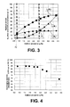
- Curved lines L E , L C , and L A of FIG. 3 are characteristic curves obtained by conducting various analysis of the battery 1 after charging/discharging.
- the curved lines L E , L C , and L A of FIG. 3 indicate a variation property for the amount of presence W E , the amount of presence W C , and the amount of presence W A with respect to each additive (variation properties normalized based on the amount of presence W E being set to 1.0 at a time the additive amount Q was 0.8 wt%). As shown in FIG.
- the curved line L C e.g., in a range of approximately 0.8 to 3.1 wt%, which was brought about by an increase in the additive amount Q, was interpreted as starting to settle into a saturated state after rising along a relatively gradual slope to a value higher than that of curved line L E .
- the curved line L A was interpreted as being maintained at an even higher value than that of the curved lines L E and L C , and rising along a relatively steep slope with respect to an increase in the additive amount Q.
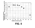
- FIG. 4 and FIG. 5 are diagrams showing a discharging capacity retention ratio property with respect to the additive amount Q (property diagrams based on a relative value of 100 for an initial capacity), which were obtained via a high temperature cycle test (temperature: 55°C; 250 cycles) and a high temperature storage test (temperature: 45°C; storage time: 24 hours) of each battery 1 used in FIG. 3 .
- the discharging capacity retention ratio property decreased as the additive amount Q was increased to exceed a predetermined value (value corresponding to intersection point P1 at 3.2 wt% in FIG. 4 and FIG 5 ).
- the amount of presence W C in the positive electrode 41 varied in response an additive adsorbed by an adsorption phenomenon.
- the amount of presence W C in the positive electrode 41 was thought to be readily present in the saturated state when compared to the amount of presence W A, which varied in response to a coating amount of a coating formed by an electrochemical reaction of the negative electrode 42.
- the additive amount Q was increased to an amount greater than that at the intersection point P1, the amount of presence W C in the positive electrode 42 was considered saturated.
- the amount of presence W E in the electrolyte increased abruptly such that there were cases where a battery life property deteriorated, e.g., a discharge capacity resulting from high temperature cycles or high temperature storage was lowered.
- an abrupt increase in the amount of presence W E was inhibited by setting the additive amount Q (e.g., setting the additive amount Q at less than 3.1 wt% as shown in FIG. 3 ) such that the additive amount Q was less than the intersection point P1, i.e., being able to maintain a relationship where an amount of presence W E ⁇ an amount of presence W C , so that the desired battery life property was easily obtained.
- the active material surface area ratio (positive electrode/negative electrode) was at least 1
- the additive amount adsorbed on the positive electrode active material surface that was larger than the surface area was relatively large as compared to the negative electrode, and a coating amount deposited by reduction formation resulting from the charging/discharging on the negative electrode surface appeared to be insufficient due to the small amount of the additive in the electrolyte. Accordingly, it was thought that the amount of presence W C > the amount of presence W A , since the positive electrode active material surface adsorption amount was not exceeded.
- an intersection point ( P2 ) in a property diagram of FIG. 3 indicated a reversed relationship between the amount of presence W C and the amount of presence W A .
- the coating formation on the negative electrode was insufficient in an area of the additive amount Q on the left side (low value side of Q ) of the intersection point P2
- the battery life property e.g., the high temperature storage discharging capacity retention ratio
- an active material surface area ratio (positive electrode/negative electrode) of at least 1 is not always feasible with respect to the convenience of material design.
- the surface area of the micropores of the positive electrode must be large, in order to attain a high input/output property in the positive electrode.
- an active material may be selected that has a large particle diameter and a small specific surface area as the material of the negative electrode, in order to attain a decrease in gas generated at a time of initial charging, high temperature charging/discharging cycles, or high temperature storage.
- An active material surface area ratio (positive electrode/negative electrode) of at least 1, which has a small denominator and a large numerator, may not be feasible under the above conditions.
- an intersection point reversing a relationship between the amount of presence W C and the amount of presence W A in system where an active material surface area ratio (positive electrode/negative electrode) was 1 or more may be a lower limit of the additive amount Q.
- a position of the intersection point P1, P2, i.e., a range of the additive amount Q that satisfied a relational expression R changed as a result of a physical property of the electrolyte, the positive electrode, or the negative electrode such as a material, a specific surface area, or the like.
- a technical concept of the present description may be similarly applied such that a range of an additive amount can be defined by the relational expression R based on an adsorption amount of an additive component to the positive electrode or the size relationship thereof, or an amount of coating formation on the negative electrode as a result of charging or an interaction with a saturation property or the like thereof.
- a reduction in an active material surface area ratio Ac/Aa is achieved by, e.g., a reduction in an average specific surface area Sc AVE of the positive electrode active layer that is formed on the positive electrode 41 (e.g., setting an average specific surface area to 0.60 m 2 /g or less).
- the additive contained in the electrolyte before charging/discharging by appropriately setting the average specific surface area Sc AVE of the positive electrode 41 or the average specific surface area Sa AVE of the negative electrode 42 is able to be induced such that the coating is effectively formed on the surface of the negative electrode 42, the residual amount of W E in the electrolyte after charging/discharging is able to be reduced, and the coating amount of the coating in the negative electrode 42 is able to be sufficiently increased, which readily contributed to an improvement in a property of the battery 1.
- the active material surface area ratio Ac/Aa was a value calculated from the only specific surface area of the active material.
- the conducting agent has a larger specific surface area and the conducting agent includes the adsorption action of the additive. Accordingly, the amount of the conducting agent is preferably reduced within a range where a property of the positive electrode 41 is uncompromised (e.g., setting to 0.1 to 3 wt%).
- each porosity may be exemplified in the positive electrode material layer 41b, 41c of the positive electrode 41 or the negative electrode material layer 42b, 42c of the negative electrode 42.
- the electrolyte amount present in the proximity of the active material particles is defined by a relationship of the positive electrode 41 ⁇ the negative electrode 42, resulting from the porosity of the positive electrode material layer 41b, 41c being smaller than the porosity of the negative electrode material layer 42b, 42c.
- the additive contained in the electrolyte before charging/discharging is able to be induced such that the coating is effectively formed on the surface of the negative electrode 42, the residual amount of W E in the electrolyte after charging/discharging is able to be reduced, and the coating amount of the coating in the negative electrode 42 is able to be sufficiently increased, which readily contributed to an improvement in a property of the battery 1, even as a result of setting a positive electrode surface area relationship or an active material specific surface area, setting a conducting agent amount, or setting a porosity.
- the desirable value (as indicated in the present description) may likewise be applicable even in cases where using another material, so long as that material is composed of a lithium ion battery type.
Landscapes
- Chemical & Material Sciences (AREA)
- Engineering & Computer Science (AREA)
- General Chemical & Material Sciences (AREA)
- Chemical Kinetics & Catalysis (AREA)
- Electrochemistry (AREA)
- Manufacturing & Machinery (AREA)
- Materials Engineering (AREA)
- Inorganic Chemistry (AREA)
- Physics & Mathematics (AREA)
- Condensed Matter Physics & Semiconductors (AREA)
- General Physics & Mathematics (AREA)
- Secondary Cells (AREA)
- Battery Electrode And Active Subsutance (AREA)
Abstract
Description
- The present description relates to a nonaqueous electrolyte secondary battery that stores a power generating element, an electrolyte, and an electrolyte additive inside an covering of a laminate film or the like.
- It is known that a nonaqueous electrolyte secondary battery such as a lithium ion secondary battery (hereinafter referred to as a "battery") is configured such that a power generating element formed by laminating one or more positive electrodes that use a lithium complex oxide or the like as an active material, one or more negative electrodes that use a carbon material or the like (e.g., graphite) as an active material, and one or more separators is stored together with an electrolyte containing a lithium salt or the like (e.g., nonaqueous electrolyte that is dissolved using a lithium salt or the like) in a covering of a laminate film or the like (laminate film, in which a synthetic resin is laminated on a surface of a metallic layer).
- While charging/discharging such as initial charging is performed in a method of manufacturing the battery, the generation of a reactant gas or the like occurs as a result of a strong reducing power of the negative electrode (electrochemical reaction that reductively decomposes the electrolyte), and the generation of the reactant gas or the like may have an affect on a property of the battery (e.g., an electrical property and a battery life property).
- A method is employed, in which a coating derived from an additive is formed on a negative electrode surface (formation such that a surface of a negative electrode material layer is covered) by performing charging/discharging of the battery after adding an electrolyte additive (hereinafter referred to as "additive") to the electrolyte, so that reductive decomposition of the electrolyte is inhibited.
- As a specific example,
Patent Literature 1 discloses technology that focuses on setting an additive amount of a sultone compound or the like contained in a solvent component of the electrolyte within a predetermined range (0.05 to 8 wt%), and improving a discharge capacity.Patent Literature 2 discloses technology that focuses on reducing an additive amount by regulating a presence of an additive component in the electrolyte after charging/discharging so as not to exceed a predetermined value (regulation such that a sulfur concentration is less than 0.05 wt%), and inhibiting a reduction in the discharge capacity. - Technical Problem
- A coating amount of a coating that is formed on a negative electrode surface in a battery having an additive amount reduced by regulating a presence of an additive component in an electrolyte alone may be insufficient.
- Based on the above technical problems, the present description provides a nonaqueous electrolyte secondary battery that attempts to sufficiently form a coating on the negative electrode surface and improve a property of the battery by defining a correlation between an abundance ratio of an additive component present in the electrolyte, an abundance ratio of an additive component present in a positive electrode, and an abundance ratio of an additive component present in a negative electrode after charging/discharging.
- The present description solves the above problem. Specifically, the present description describes a battery subjected to a charging/discharging including at least initial charging configured such that a power generating element formed by laminating a positive electrode and a negative electrode separated by a separator is stored within a covering together with a nonaqueous electrolyte and an additive, and the covering is sealed with a terminal leading out of the covering. Moreover, the present description describes that a relational expression RE < RC < RA is defined by using a total amount of WE in the additive component present in the electrolyte, WC in the additive component present in the positive electrode, and WA in the additive component present in the negative electrode after charging/discharging as WT, and by using an abundance ratio of WE with respect to the total amount of WT as RE, an abundance ratio of WC with respect to the total amount of WT as RC, and an abundance ratio of WA with respect to the total amount of WT as RA.
- According to a battery of the present description, a coating is sufficiently formed on a negative electrode surface, and the sufficient formation of the coating on the negative electrode surface may contribute to an improvement in a battery property.
-
-
FIG. 1 shows a schematic perspective view according to one embodiment of a battery of a present description; -
FIG. 2 shows a schematic perspective view of abattery 1 ofFIG. 1 ; -
FIG. 3 shows a variation property diagram of WE in an additive component present in an electrolyte, WC in an additive component present in a positive electrode, and WA in an additive component present in a negative electrode with respect to an additive amount Q ofbattery 1; -
FIG. 4 shows a discharging capacity maintenance factor property diagram with respect to an additive amount Q according to a high temperature cycle test ofbattery 1; and -
FIG. 5 shows a discharging capacity maintenance factor property diagram with respect to an additive amount Q according to a high temperature storage test ofbattery 1. - An embodiment of the present description will be explained hereinafter. A battery of the present embodiment may be exemplified by a film-covered-type nonaqueous secondary battery 1 (hereinafter referred to as a "battery") of
FIG. 1 andFIG. 2 . Thebattery 1 is, e.g., a lithium ion battery. The battery has a flat rectangular outer shape, and includes a pair ofterminals - As seen in
FIG. 2 , thebattery 1 is configured to store a power generatingelement 4 constituting a rectangular shape (as seen from a direction of an arrow X) and an electrolyte (not shown) inside acovering 5 composed of a laminate film. The power generatingelement 4 includes alternately laminated rectangular plate-shapedpositive electrodes 41 andnegative electrodes 42 that are separated byseparator 43, e.g., threenegative electrodes 42, twopositive electrodes 41, and fourseparators 43 therebetween. Because an accurate measurement of each portion inFIG. 2 is not required, a measurement of each portion has been enlarged for better understanding of the present description. - The
positive electrode 41 is formed of a porous positive electrodeactive material layer current collector 41a, as seen from a direction of an arrow X in FIG.* 1 andFIG. 2 . The positiveelectrode current collector 41a is composed of an electrochemically stable metal foil, e.g., an aluminum foil, an aluminum alloy foil, a copper foil, or a nickel foil. In addition, the positive electrodeactive material layer - The
negative electrode 42 is formed of a porous negative electrodeactive material layer current collector 42a, as seen from a direction of an arrow X inFIG. 1 andFIG. 2 . The negativeelectrode current collector 42a is composed of an electrochemically stabilized metal foil, e.g., a copper foil, a stainless steel foil, or an iron foil. The negative electrodeactive material layer - A portion of an edge of the lengthwise direction of the negative electrode
current collector 42a extends as anextension 40 that lacks the negative electrodeactive material layer end 40a of theextension 40 is fixed to oneend 3a of an inside of thecovering 5. In a case where there are plurality of negative electrodecurrent collectors 42a, theends 40a of eachextension 40 of the plurality ofnegative collectors 42a are integrated together by a method such ultrasonic welding. - Similarly, one portion of the lengthwise direction of the positive electrode
current collector 41a not shown inFIG. 2 extends as an extension that lacks the positive electrodeactive material layer extension 40; not shown inFIG. 2 ), and an end of the extension is fixed to one end of the inside of the covering 5 at apositive electrode terminal 2. - The
separator 43 functions to prevent a short circuit between thepositive electrode 41 and thenegative electrode 42, while simultaneously storing electrolytes. Theseparator 43 is composed of a microporous membrane formed of a polyolefin or the like, e.g., polyethylene (PE) or polypropylene (PP). The monolayered membrane of polyolefin or the like is not particularly limited as theseparator 43. Accordingly, a three-layered configuration sandwiching a polypropylene membrane between two polyethylene membranes or a layered configuration of a polyolefin microporous membrane and a laminate to which an inorganic insulating particle is binded may be employed. - The covering 5 configured to store the power generating
element 4 that constitutes a layered configuration of the electrode and the separator, along with the electrolyte or the additive therein, is composed of a laminate film having a three-layered configuration including: athermal bonding layer 51, ametallic layer 52, and aprotective layer 53, such as that indicated in an enlarged portion ofFIG. 2 . The intermediarymetallic layer 52 may be formed of an aluminum foil or the like, thethermal bonding layer 51 that covers the inner surface of the covering may be formed of a synthetic resin that allows thermal bonding, e.g., polypropylene (PP), and theprotective layer 53 that covers the outer surface of themetallic layer 52 may be formed of a synthetic resin having superior durability, e.g., polyethylene terephthalate (PET). A laminate film having a plurality of layers may also be employed. Moreover, while the synthetic resin layer is laminated on both sides of themetallic layer 52 in the abovementioned example, the synthetic resin layer on the outer side of themetallic layer 52 is considered optional. Accordingly, a configuration including only the synthetic resin layer on the inner surface is also possible. - In one example, the covering 5 forms a configuration constituting one laminate film disposed on a lower surface side of the power generating
element 4 and another laminate film disposed on an upper surface side ofFIG. 2 , the four peripheral edges of these two laminate films are superimposed, and these edges are thermally bonded to each other. Illustrative embodiments show the covering 5 comprising a two-layered-laminate. Moreover, in another example, thecovering 5 is composed of one comparatively large laminate film, three peripheral edges of thecovering 5 are superimposed above a double-folded power generatingelement 4 disposed therewithin, and the three peripheral edges are thermally bonded to each other. - A
terminal 2 and aterminal 3 disposed on a shorter edge of a rectangular-shaped battery 1 are each fixed to the extensions of thecurrent collector 41a and thecurrent collector 42a on one end (in thecurrent collector 42a, one end is the "extension 40") of the inner side of the covering 5 during thermal bonding of the laminate film of thecovering 5, and another end (in thenegative electrode terminal 3, another end is "anotherend 3b") of the outer side of the covering 5 passes through afixing surface 5a of the laminate film so as to protrude from the exterior. In addition, theterminal 2 and theterminal 3 are sandwiched between one end and another end (in thenegative electrode terminal 3, the part is "between oneend 3a and anotherend 3b") by thefixing surface 5a of the laminate film of thecovering 5, and sealed in asandwiching portion 3c sandwiched therewith. - The electrolyte of
battery 1, as shown inFIG. 1 andFIG. 2 , is not particularly limited. For example, a nonaqueous electrolyte may be used that contains a lithium salt such as LiPF6 or LiBF4 dissolved in an organic solvent such as ethylene carbonate, propylene carbonate, diethyl carbonate, dimethyl carbonate, ethylmethyl carbonate, or γ-butyrolactone as the electrolyte typically employed in a lithium ion secondary battery. Moreover, the above electrolyte is not particularly limited to a liquid solution. For example, a semi-solid electrolyte such as a gel electrolyte may also be employed. - An amount of the electrolyte is not particularly limited. An amount of the electrolyte may be set to be 1.2 to 1.5 times a total value of a hole volume of the
electrode 41, theelectrode 42 and the separator 43 (a hole volume of the power generating element 4), as a specific example that exceeds 1.0 times the above value. - The additive is reductively decomposed by the negative electrode active material to form the coating on the surface (an active surface) (see, negative electrode
active material 42b inFIG. 1 andFIG. 2 ) during charging/discharging that at least includes initial charging. Thus, so long as an amount of presence WE in an additive component included in the electrolyte, an amount of presence WC in an additive component included in thepositive electrode 41, and an amount of presence WA in an additive component included in thenegative electrode 42 is observable by decomposingbattery 1 after charging/discharging, various modifications may be applied thereto. - Specifically, a sulfone compound, sulfur-containing compound such as a sulfonic ester may be exemplified. The sulfur containing compound may be employed alone or in combinations of one or more. A rigid protective coating may be formed on the negative electrode surface by using the sulfur compound, and therefore a cycle characteristic may be improved. In a case where using the sulfur containing compound as the additive, a method of quantitative analyzing sulfur such as that mentioned hereinafter is preferably employed during observation of WE, WC, and WA.
- Sulfone compound containing a saturated hydrocarbon group such as dimethyl sulfone, diethyl sulfone, or ethylmethyl sulfone; a sulfone compound containing an unsaturated hydrocarbon group such as divinyl sulfone, methyl vinyl sulfone, ethyl vinyl sulfone, diphenyl sulfone, or phenyl vinyl sulfone; or a cyclic sulfone such as sulfolane may be exemplified as the sulfone compound.
- A sulfonic ester containing an straight-chained saturated hydrocarbon group such as methyl methane sulfonate or methyl ethane sulfonate; a sulfonic ester containing an straight-chained unsaturated hydrocarbon group such as methyl vinyl sulfonate or ethyl vinyl sulfonate; an aromatic sulfonic ester such as methyl benzene sulfonate, or ethyl benzene sulfonate; a cyclic sulfonic ester containing a saturated hydrocarbon group such as ethane sultone, propane sultone, butane sultone, or 1,5-pentane sultone; or a cyclic sulfonic ester containing an unsaturated hydrocarbon group such as ethylene sultone, 3-hydroxy-1-propene sulfonic acid-γ-sultone, 4-hydroxy-1-butylene sulfonic acid-γ-sultone, or 5-hydroxy-1-pentene sulfonic acid-γ-sultone may be exemplified as the sulfonic acid ester.
- With respect to an amount of additive (hereinafter referred to as an "additive amount"), a relational expression R cannot be established in cases where the additive amount is deficient or excessive as described hereinafter. The coating may be formed in a proper coating amount on the negative electrode 42 (surface of negative electrode
active material layer active material layer - First, an example of a method of manufacturing the
battery 1 includes forming thepower generating element 4 by sequentially laminating thenegative electrode 42, theseparator 43, and thepositive electrode 41, and attaching an inner end (oneend 3a) of thenegative electrode terminal 3 that is initially thermally bonded to theextension 40 of the negative electrodecurrent collector 42a of thenegative electrode 42 by a resin layer 33. Likewise, the inner end of the initially thermally bonded positive electrode terminal 2 (corresponding to oneend 3a of the negative terminal 3) is fixed to theextension 40 of thepositive electrode collector 41a of thepositive electrode 41 by the resin layer 33. Then, while thepower generating element 4 is covered by the laminate film that forms thecovering 5, the three peripheral edges (in a case where folded in two, two edges are thermally bonded) are thermally bonded such that one edge remains unbonded. Next, the electrolyte that at least includes a combination of one or more additives is injected through the one remaining edge that has not been thermally bonded into thecovering 5, the pressure inside thecovering 5 is reduced, and thecovering 5 is tightly sealed by thermally bonding the one edge that employed an injection liquid. As a result, a configuration of thebattery 1 is completed. - Afterwards, the coating derived from the additive is formed by adhering the reductively decomposed additive in the electrolyte to an active material particle surface in negative electrode
active material layer terminal 2 and theterminal 3 under a predetermined condition and charging/discharging that at least includes an initial charge. On the positive electrode side, the coating derived from the additive is formed by adhering the additive in the electrolyte to an active material particle surface in positive electrodeactive material layer - The amount of presence WE in an additive component included in the electrolyte, the amount of presence WC in an additive component included in the
positive electrode 41, the amount of presence WC in an additive component included in thenegative electrode 42 of thebattery 1 after charging/discharging may be observable by a method indicated hereinafter. - First, the
battery 1 was disassembled after charging/discharging, the electrolyte was extracted by using a centrifuge, and an electrolyte sample ME was obtained. In addition, thepositive electrode 41 and thenegative electrode 42 were disassembled from thebattery 1, and a positive electrode sample MC and a negative electrode sample MA were obtained. - The amount of presence WE in the additive component included in the electrolyte sample may be calculated by sampling a portion from the electrolyte sample ME, obtaining a measured solution by dilution with an organic solvent, determining a concentration of a sulfur contained in the above collected sample after being quantified by inductively coupled plasma atomic emission spectrophotometry of a specific component (e.g., sulfur (S)) of an additive within the measured solution, and multiplying by the electrolyte amount present in the battery.
- The amount of presence WC in the additive component included in the positive electrolyte sample MC and the amount of presence WA in the additive component included in the negative electrolyte sample MA can be calculated by sampling a portion from the positive electrolyte sample MC and sampling a portion from the negative electrolyte sample MA, burning the portion sampled from the positive electrolyte sample MC and the portion sampled from the negative electrolyte sample MA, collecting a gas generated by burning of the sample partially collected from the positive electrolyte sample MC and collecting a gas generated by burning of the sample partially collected from the negative electrolyte sample MA using an absorbing solution, determining a concentration of sulfur contained in the collected positive electrolyte sample MC after being quantified by inductively coupled plasma atomic emission spectrophotometry for a specific component (e.g., sulfur (S)) of an additive and determining a concentration of sulfur contained in the collected negative electrolyte sample MA after being quantified by inductively coupled plasma atomic emission spectrophotometry for a specific component (e.g., sulfur (S)) of an additive, and multiplying by a weight of the positive electrolyte sample MC and the negative electrolyte sample MA present in the battery.
- A method of observing a specific sulfur component of an additive by inductively coupled plasma atomic emission spectrophotometry or ion chromatography as described above is thought to allow for the amount of presence WE in an additive component included in the total electrolyte, the amount of presence WC in the additive component included in the total positive electrode layer, and the amount of presence WA in the additive component included in the total negative electrode layer to be more accurately observed when compared to X-ray photoelectron spectroscopy that only observes part of an object (surface only).
- An average active material specific surface area ScAVE of the positive electrode active material layer is indicated hereinafter with respect to a specific surface area Scn (Sc1, Sc2, Sc3, ...... , Scn-1, Scn) (unit: m2/g) of each material of n-type active material particles and a weight ratio Pcn thereof (Pc1, Pc2, Pc3, ...... , Pcn-1, Pcn) (total = 1).

- Likewise, an average active material specific surface area SaAVE of the negative electrode active material layer with respect to San and Pcn is as:

- On the other hand, in a case where a weight of each material of the n-type active material particles contained in the positive electrode active material layer (hereinafter referred to as a "positive electrode active material layer per unit area") on the positive electrode current collector formed per unit area is Mcn (unit: g/m2), a total surface area of a total active material particle forming micropores in the positive electrode active material layer per unit area Ac can be calculated as indicated hereinafter.

- Likewise, with respect to the negative electrode:

- Ac/Aa that reflects the above ratio indicates the ratio of the positive electrode and the negative electrode of the surface area of micropores formed by the active material particle (hereinafter, also referred to as an "active material surface area ratio").
- A comparative surface area may be measured by a typical BET method.
- With regard to a porosity of the positive electrode
active material layer positive electrode 41 or the like or at a porosity of the negative electrodeactive material layer negative electrode 42 or the like, a determination can be made by multiplying a reciprocal of a true density of each component in each constituent particle weight or binder weight included in the active material layer on a current collector formed per unit area, dividing the value thereof by a volume of the active material layer on a current collector formed per unit area, and subtracting the value thereof from 1. - An abundance ratio RE, an abundance ratio RC, and an abundance ratio RA that relate to the relational expression R can each be derived from the below-mentioned equation by preparing the
battery 1 that is configured by using various additive amounts Q of the additive, observing the amount of presence WE of the additive component in the electrolyte, the amount of presence WC of the additive component in thepositive electrode 41, and the amount of presence WA of the additive component in thenegative electrode 42 after charging/discharging in eachbattery 1, and determining the total amount of WE, WC, and WA as (total) WT.


battery 1 satisfies the relational expression R defined by RE, RC, and RA, the relationship regarding an amount of presence WE < an amount of presence WC and the relationship regarding an amount of presence WC < an amount of presence WA are maintained, and superior properties such as those mentioned hereinafter (e.g., an electrical property and a battery life property) may be obtained. - A battery for analysis was prepared by using 3% carbon-type conducting agent added to an active material composite containing a spinel-type lithium-manganese complex oxide and a lithium-nickel-type complex oxide as the positive electrode, using a carbon-type negative electrode as the negative electrode to form opposing electrodes separated via a polyolefin-type micrporous membrane as a separator, and immersing the opposing electrodes separated via the separator in an nonaqueous electrolyte solution comprising a cyclic disulfonic ester as an additive. The employed covering or method was as described above. The average active material specific surface area ScAVE of the active material composite of the positive electrode was 0.53 m2/g. An active material surface area ratio Ac/Aa was 1.44 and a porosity ratio (positive/negative) was 0.76.
- The measurements of the additive component contained in the electrolyte, the additive component contained in the positive electrode, and the additive component contained in the negative electrode were conducted according to the above-described technique via the below-described device. The amount of presence WE of the additive component contained in the electrolyte was calculated by quantifying sulfur using inductively coupled plasma atomic emission spectrophotometry (inductively coupled plasma atomic emission spectrophotometry device: Ultima 2C, manufactured by HORIBA, Ltd.), and the amount of presence WC of the additive component contained in the
positive electrode 41 and the amount of presence WA of the additive component contained in thenegative electrode 42 were calculated by quantifying sulfur using an ion chromatography (device requirements: AQF-100, manufactured by Dia Instruments Co., Ltd. and ICS-3000, manufactured by Dionex Corporation; maximum temperature of combustion at 1100°C). - Curved lines LE, LC, and LA of
FIG. 3 are characteristic curves obtained by conducting various analysis of thebattery 1 after charging/discharging. The curved lines LE, LC, and LA ofFIG. 3 indicate a variation property for the amount of presence WE, the amount of presence WC, and the amount of presence WA with respect to each additive (variation properties normalized based on the amount of presence WE being set to 1.0 at a time the additive amount Q was 0.8 wt%). As shown inFIG. 3 , the curved line LC, e.g., in a range of approximately 0.8 to 3.1 wt%, which was brought about by an increase in the additive amount Q, was interpreted as starting to settle into a saturated state after rising along a relatively gradual slope to a value higher than that of curved line LE. The curved line LA was interpreted as being maintained at an even higher value than that of the curved lines LE and LC, and rising along a relatively steep slope with respect to an increase in the additive amount Q. While a period of rise for the curved line LC was maintained at a relatively low value with respect the curved line LE, the curved line LC gradually began to rise when approaching a saturated state, and an intersection with the curved line LC was seen at a predetermined additive amount Q (additive amount Q ≈ 3.1 wt% inFIG. 3 ), i.e., an intersection at intersection point P1 inFIG. 3 . - Next, in the curved line LC along a larger quantity range than that where an additive Q intersects intersection point P1 (additive amount Q exceeds 3.1 wt% in
FIG. 3 ), it was obvious that a saturated state was maintained without change in a curved line LC even in cases where the additive amount Q was increased. It was obvious that the curved line LA formed a slope that gradually rose with respect to an increase in the additive amount Q, and started to settle into a saturated state. The curved line LE rose along a high gradient as the curved line LA approached a saturated state. -
FIG. 4 andFIG. 5 are diagrams showing a discharging capacity retention ratio property with respect to the additive amount Q (property diagrams based on a relative value of 100 for an initial capacity), which were obtained via a high temperature cycle test (temperature: 55°C; 250 cycles) and a high temperature storage test (temperature: 45°C; storage time: 24 hours) of eachbattery 1 used inFIG. 3 . According toFIG. 4 andFIG. 5 , the discharging capacity retention ratio property decreased as the additive amount Q was increased to exceed a predetermined value (value corresponding to intersection point P1 at 3.2 wt% inFIG. 4 andFIG 5 ). - Although the details are unclear, the below-mentioned mechanism was thought to be relevant. The amount of presence WC in the
positive electrode 41 varied in response an additive adsorbed by an adsorption phenomenon. The amount of presence WC in thepositive electrode 41 was thought to be readily present in the saturated state when compared to the amount of presence WA, which varied in response to a coating amount of a coating formed by an electrochemical reaction of thenegative electrode 42. In a case where the additive amount Q was increased to an amount greater than that at the intersection point P1, the amount of presence WC in thepositive electrode 42 was considered saturated. Thus, an increment in the additive amount Q was reflected in the amount of presence WE in the electrolyte and the amount of presence WA in thenegative electrode 41, the amount of presence WA in thenegative electrode 42 approached saturation, and the amount of presence WE in the electrolyte rapidly increased. Accordingly, it was thought that the above brought about a reduction in discharge capacity in a high temperature charge/discharge cycle test or a high temperature storage test. It was thought that the amount of moveable lithium ions was reduced by gas generation or elevated resistance via excessive decomposition of the additive present in the electrolyte. - Subsequently, in a case where the additive amount Q exceeded an intersection point P1, the amount of presence WE in the electrolyte increased abruptly such that there were cases where a battery life property deteriorated, e.g., a discharge capacity resulting from high temperature cycles or high temperature storage was lowered. However, an abrupt increase in the amount of presence WE was inhibited by setting the additive amount Q (e.g., setting the additive amount Q at less than 3.1 wt% as shown in
FIG. 3 ) such that the additive amount Q was less than the intersection point P1, i.e., being able to maintain a relationship where an amount of presence WE < an amount of presence WC, so that the desired battery life property was easily obtained. - A relationship in which the amount of presence WC < the amount of presence WA was barely maintained at the relatively small amount of the additive amount Q in
FIG. 3 , e.g., the additive amount Q inFIG. 3 that was 0.8 wt%. In a case where the relationship in which the amount of presence WC < the amount of presence WA was maintained, it was obvious that a volume expansion of thebattery 1 was sufficiently inhibited (as shown in Table 1) after a percentage of volume change (percentage of change before and after initial charging) of the battery was tested with respect the additive amount Q.Table 1 Additive amount Q (wt%) 0 0.8 1.6 2.0 2.4 2.8 3.2 3.6 Rate of volume change (Volume multiplication factor) 1.39 1.19 1.14 1.12 1.08 1.07 1.05 1.04 - On the other hand, in a case where the additive amount Q was less than 0.8 wt% such as that shown in
FIG. 3 , it was understood based on the figure that the relationship in which the amount of presence WC < the amount of presence WA was not maintained. As a battery performance under the above conditions, even in a case where a relatively large volume expansion occurred in thebattery 1 as seen in Table 1 e.g., the additive amount was 0, or the additive amount Q was not 0 as seen inFIG. 5 , it was understood that a high temperature storage discharging capacity retention ratio was reduced over a region of less than 0.8 wt%. While the details are unclear with regard to a mechanism of such a correlation, the additive required in a protective coating formation of the negative electrode was adsorbed to the positive electrode. As a result, it is thought that a negative electrode protective function was insufficient, and thus gas production during initial charging/discharging was increased. - While the details are unclear, it is thought that a reason that the relationship between the amount of presence WC and the amount of presence WA reversed at a time where the additive amount Q was small was as follows. The additive that is present in the electrolyte in a large quantity was adsorbed on the active material surface of the micropores in the positive electrode and the negative electrode in a case where the additive amount Q was small. Accordingly, the additive that contributed to a coating formation by reduction on the electrode surface as a result of the discharging/charging thereafter was already very small. In a case where the active material surface area ratio (positive electrode/negative electrode) was at least 1, the additive amount adsorbed on the positive electrode active material surface that was larger than the surface area was relatively large as compared to the negative electrode, and a coating amount deposited by reduction formation resulting from the charging/discharging on the negative electrode surface appeared to be insufficient due to the small amount of the additive in the electrolyte. Accordingly, it was thought that the amount of presence WC > the amount of presence WA, since the positive electrode active material surface adsorption amount was not exceeded.
- As previously described, in a case where the active material surface area ratio (positive electrode/negative electrode) was at least 1, an intersection point (P2) in a property diagram of
FIG. 3 indicated a reversed relationship between the amount of presence WC and the amount of presence WA. Because the coating formation on the negative electrode was insufficient in an area of the additive amount Q on the left side (low value side of Q) of the intersection point P2, it was thought that a large amount of gas was generated, the volume of the battery was increased, and the battery life property, e.g., the high temperature storage discharging capacity retention ratio, was specifically deteriorated. The area was thought to broaden as a value of the active material surface area ratio (positive electrode/negative electrode) increased. - Accordingly, having an active material surface area ratio (positive electrode/negative electrode) of at least 1 is not always feasible with respect to the convenience of material design. For example, the surface area of the micropores of the positive electrode must be large, in order to attain a high input/output property in the positive electrode. In addition, an active material may be selected that has a large particle diameter and a small specific surface area as the material of the negative electrode, in order to attain a decrease in gas generated at a time of initial charging, high temperature charging/discharging cycles, or high temperature storage. An active material surface area ratio (positive electrode/negative electrode) of at least 1, which has a small denominator and a large numerator, may not be feasible under the above conditions.
- It is understood that an intersection point reversing a relationship between the amount of presence WC and the amount of presence WA in system where an active material surface area ratio (positive electrode/negative electrode) was 1 or more may be a lower limit of the additive amount Q.
- As previously mentioned, the following have been determined from the results shown in
FIGS. 3 to 5 and Table 1. First, it was understood that so long as the additive amount Q was equal to or greater than a intersection point reversing a relationship between the amount of presence WC and the amount of presence WA, the coating amount of the coating formed by an electrochemical reaction of thenegative electrode 42 was sufficient, the volume expansion of thebattery 1 by generation of a reactive gas (reactive gas resulting from reductive decomposition of the electrolyte) was able to be sufficiently inhibited, and a superior value was able to be obtained for a high temperature storage discharging capacity retention ratio. On the other hand, in a case where the additive amount Q exceeded an intersection point P1 where a relationship between the amount of presence WC* and the amount of presence WA reversed, it was understood that the amount of the presence WE in the electrolyte increased abruptly such that there were cases where a battery life property deteriorated, e.g., there were cases where a discharge capacity resulting from high temperature cycles or high temperature storage was lowered. - It was thought that a position of the intersection point P1, P2, i.e., a range of the additive amount Q that satisfied a relational expression R, changed as a result of a physical property of the electrolyte, the positive electrode, or the negative electrode such as a material, a specific surface area, or the like. Subsequently, even in a case where a material system differs from that exemplified in the present specification, a technical concept of the present description may be similarly applied such that a range of an additive amount can be defined by the relational expression R based on an adsorption amount of an additive component to the positive electrode or the size relationship thereof, or an amount of coating formation on the negative electrode as a result of charging or an interaction with a saturation property or the like thereof.
- The results shown in Table 2 were obtained after testing a variation property of the discharging capacity maintenance factor with respect to the additive amount Q, using different settings for an active material surface area ratio Ac/Aa (positive electrode/negative electrode) in the
battery 1 employed inFIGS. 3 to 5 .Table 2 Additive amount Q Active material surface area ratio Amount of presence (relative value when WT= 100) Discharging capacity retention ratio (Ac/Aa) WE WC WA 0.8 wt% 1.92 3% 47% 50% 73.8% 1.44 4% 43% 53% 86.2% 1.25 4% 42% 54% 88.6% Additive amount Q Active material surface area ratio Amount of presence (relative value when WT= 100) Discharging capacity retention ratio (Ac/Aa) WE WC WA 1.6 wt% 1.92 6% 35% 59% 74.8% 1.44 7% 31% 62% 87.4% 1.25 7% 30% 63% 89.8% Additive amount Q Active material surface area ratio Amount of presence (relative value when WT= 100) Discharging capacity retention ratio (Ac/Aa) WE WC WA 2.4 wt% 1.92 14% 31% 55% 73.1% 1.44 15% 27% 58% 85.4% 1.25 15% 26% 59% 87.7% Additive amount Q Active material surface area ratio Amount of presence (relative value when WT= 100) Discharging capacity retention ratio (Ac/Aa) WE WC WA 3.2 wt% 1.92 23% 26% 51% 69.3% 1.44 24% 22% 54% 81.0% 1.25 24% 21% 55% 83.2% Additive amount Q Active material surface area ratio Amount of presence (relative value when WT= 100) Discharging capacity retention ratio (Ac/Aa) WE WC WA 3.6 wt% 1.92 27% 24% 49% 67.2% 1.44 28% 20% 52% 78.5% 1.25 29% 19% 52% 80.7% - It was understood that a large difference existed in each property in a case where the active material surface area ratio Ac/Aa was 1.92 and the active material surface area ratio Ac/Aa was 1.44 (in a case where an average specific surface area of the positive electrode was 0.53 m2/g) or less (1.25), based on the results indicated in Table 2. Accordingly, it is understood that a battery having a sufficiently superior life property (discharging capacity retention ratio) is obtained by setting the active material surface area ratio Ac/Aa to a smaller value, e.g., a setting equal to or less than 1.8, without being defined by the relational expression R alone. A reduction in an active material surface area ratio Ac/Aa (equal to or less than 1.8) is achieved by, e.g., a reduction in an average specific surface area Sc AVE of the positive electrode active layer that is formed on the positive electrode 41 (e.g., setting an average specific surface area to 0.60 m2/g or less).
- Accordingly, the additive contained in the electrolyte before charging/discharging by appropriately setting the average specific surface area ScAVE of the
positive electrode 41 or the average specific surface area SaAVE of thenegative electrode 42 is able to be induced such that the coating is effectively formed on the surface of thenegative electrode 42, the residual amount of WE in the electrolyte after charging/discharging is able to be reduced, and the coating amount of the coating in thenegative electrode 42 is able to be sufficiently increased, which readily contributed to an improvement in a property of thebattery 1. - The active material surface area ratio Ac/Aa was a value calculated from the only specific surface area of the active material. However, in a case where a carbon-type conducting agent is added to the positive electrode, the conducting agent has a larger specific surface area and the conducting agent includes the adsorption action of the additive. Accordingly, the amount of the conducting agent is preferably reduced within a range where a property of the
positive electrode 41 is uncompromised (e.g., setting to 0.1 to 3 wt%). - The appropriate selection of each porosity may be exemplified in the positive
electrode material layer positive electrode 41 or the negativeelectrode material layer negative electrode 42. For example, it is preferable in order to easily satisfy the relational expression R, that the electrolyte amount present in the proximity of the active material particles is defined by a relationship of thepositive electrode 41 < thenegative electrode 42, resulting from the porosity of the positiveelectrode material layer electrode material layer - As previously mentioned, the additive contained in the electrolyte before charging/discharging is able to be induced such that the coating is effectively formed on the surface of the
negative electrode 42, the residual amount of WE in the electrolyte after charging/discharging is able to be reduced, and the coating amount of the coating in thenegative electrode 42 is able to be sufficiently increased, which readily contributed to an improvement in a property of thebattery 1, even as a result of setting a positive electrode surface area relationship or an active material specific surface area, setting a conducting agent amount, or setting a porosity. The desirable value (as indicated in the present description) may likewise be applicable even in cases where using another material, so long as that material is composed of a lithium ion battery type. -
- 1 Battery;
- 2, 3 Terminal;
- 4 Power generating element;
- 41 Positive electrode;
- 42 Negative electrode;
- 43 Separator; and
- 5 Covering.
-
- Patent Literature 1:
JP-A 2000-123868 - Patent Literature 2:
JP-A 2006-004811
Claims (5)
- A nonaqueous electrolyte secondary battery, subjected to a charging/discharging including at least an initial charging, storing a power generating element formed by laminating a positive electrode and a negative electrode separated by a separator, a nonaqueous electrolyte and an additive within a covering that is sealed with a terminal led outwardly, the nonaqueous electrolyte secondary battery comprising:a relational expression RE < RC < RA defined by using a total amount of presence WE of the additive component in the electrolyte, an amount of presence WC of the additive component in the positive electrode, and an amount of presence WA of the additive component in the negative electrode after the charging/discharging as WT, and by using an abundance ratio of WE with respect to WT as RE, an abundance ratio of WC with respect to WT as RC, and an abundance ratio of WA with respect to WT as RA.
- The nonaqueous electrolyte secondary battery according to claim 1, wherein a ratio of a surface area of a positive electrode active material layer formed on the positive electrode with respect to a surface area of a negative electrode active material layer formed on the negative electrode is 1.8 or less.
- The nonaqueous electrolyte secondary battery according to claim 1, wherein an average specific surface area of the positive electrode active material layer is 0.60 m2/g or less.
- The nonaqueous electrolyte secondary battery according to claims 1 to 3, wherein a conducting agent contained in the positive electrode active material layer is 3 wt% or less.
- The nonaqueous electrolyte secondary battery according to claims 1 to 4, wherein a porosity of the positive electrode active material layer is less than a porosity of the negative electrode active material layer.
Applications Claiming Priority (1)
| Application Number | Priority Date | Filing Date | Title |
|---|---|---|---|
| JP2013214218A JP6081339B2 (en) | 2013-10-11 | 2013-10-11 | Nonaqueous electrolyte secondary battery |
Publications (1)
| Publication Number | Publication Date |
|---|---|
| EP2860797A1 true EP2860797A1 (en) | 2015-04-15 |
Family
ID=51661976
Family Applications (1)
| Application Number | Title | Priority Date | Filing Date |
|---|---|---|---|
| EP20140188144 Withdrawn EP2860797A1 (en) | 2013-10-11 | 2014-10-08 | Nonaqueous electrolyte secondary battery |
Country Status (5)
| Country | Link |
|---|---|
| US (1) | US20150104699A1 (en) |
| EP (1) | EP2860797A1 (en) |
| JP (1) | JP6081339B2 (en) |
| KR (1) | KR20150042714A (en) |
| CN (1) | CN104577182A (en) |
Families Citing this family (6)
| Publication number | Priority date | Publication date | Assignee | Title |
|---|---|---|---|---|
| JP6860125B2 (en) * | 2017-01-06 | 2021-04-14 | 学校法人早稲田大学 | Secondary battery |
| CN110998960B (en) | 2017-07-25 | 2023-07-07 | 株式会社村田制作所 | Lithium-ion secondary battery |
| JP6927307B2 (en) * | 2017-07-25 | 2021-08-25 | 株式会社村田製作所 | Lithium ion secondary battery |
| CN108598576A (en) * | 2018-07-06 | 2018-09-28 | 兰州理工大学 | A kind of lithium-ion battery electrolytes |
| JP7714864B2 (en) * | 2020-06-30 | 2025-07-30 | 株式会社Gsユアサ | Nonaqueous electrolyte storage element and method for manufacturing same |
| EP4184606A4 (en) * | 2020-07-20 | 2024-11-06 | Panasonic Intellectual Property Management Co., Ltd. | POSITIVE ELECTRODE FOR BATTERIES AND BATTERY |
Citations (7)
| Publication number | Priority date | Publication date | Assignee | Title |
|---|---|---|---|---|
| JP2000123868A (en) | 1998-10-20 | 2000-04-28 | Hitachi Maxell Ltd | Non-aqueous secondary battery |
| JP2002329528A (en) * | 2001-03-01 | 2002-11-15 | Mitsui Chemicals Inc | Nonaqueous electrolyte, secondary battery using it and additive for electrolyte |
| US20030118914A1 (en) * | 2001-11-01 | 2003-06-26 | Sumio Mori | Nonaqueous electrolyte secondary battery |
| JP2006004811A (en) | 2004-06-18 | 2006-01-05 | Toshiba Corp | Nonaqueous electrolyte secondary battery |
| JP4537851B2 (en) * | 2002-08-29 | 2010-09-08 | 株式会社東芝 | Nonaqueous electrolyte secondary battery |
| US20110200886A1 (en) * | 2009-09-29 | 2011-08-18 | Masaki Deguchi | Non-aqueous electrolyte and non-aqueous electrolyte secondary battery using the same |
| US20130122353A1 (en) * | 2010-09-02 | 2013-05-16 | Nec Corporation | Secondary battery |
Family Cites Families (22)
| Publication number | Priority date | Publication date | Assignee | Title |
|---|---|---|---|---|
| JP3883726B2 (en) * | 1999-02-15 | 2007-02-21 | 三洋電機株式会社 | Non-aqueous electrolyte secondary battery |
| JP2002373660A (en) * | 2001-06-18 | 2002-12-26 | Hitachi Maxell Ltd | Non-aqueous secondary battery |
| JP2003272611A (en) * | 2002-03-20 | 2003-09-26 | Japan Storage Battery Co Ltd | Non-aqueous electrolyte secondary battery |
| US7027852B2 (en) * | 2002-05-21 | 2006-04-11 | Pacesetter, Inc. | Lead with distal tip surface electrodes connected in parallel |
| WO2005029613A1 (en) * | 2003-09-16 | 2005-03-31 | Nec Corporation | Nonaqueous electrolyte secondary battery |
| JP2006156021A (en) * | 2004-11-26 | 2006-06-15 | Toshiba Corp | Nonaqueous electrolyte secondary battery |
| JP5105393B2 (en) * | 2005-03-02 | 2012-12-26 | 日立マクセルエナジー株式会社 | Nonaqueous electrolyte secondary battery |
| KR100770105B1 (en) * | 2005-07-06 | 2007-10-24 | 삼성에스디아이 주식회사 | Lithium secondary battery |
| JP4688604B2 (en) * | 2005-08-05 | 2011-05-25 | 日立ビークルエナジー株式会社 | Lithium ion battery |
| KR100969130B1 (en) * | 2006-08-25 | 2010-07-07 | 주식회사 엘지화학 | Non-aqueous electrolyte with enhanced water resistance and lithium secondary battery comprising same |
| US8846224B2 (en) * | 2006-10-16 | 2014-09-30 | Lg Chem, Ltd. | High power secondary battery system comprising asymmetric charged cells |
| CN101423494A (en) * | 2008-12-03 | 2009-05-06 | 中国科学院上海有机化学研究所 | Tetrahydro chinolines derivates and synthetic method |
| JP2010140765A (en) * | 2008-12-11 | 2010-06-24 | Sony Corp | Nonaqueous electrolyte battery |
| JPWO2011096572A1 (en) * | 2010-02-08 | 2013-06-13 | Necエナジーデバイス株式会社 | Non-aqueous electrolyte secondary battery |
| JP2011171177A (en) * | 2010-02-19 | 2011-09-01 | Toyota Central R&D Labs Inc | Lithium ion secondary battery |
| JP5471598B2 (en) * | 2010-03-02 | 2014-04-16 | ソニー株式会社 | Non-aqueous electrolyte battery |
| EP2639861B1 (en) * | 2010-11-12 | 2016-10-26 | Toyota Jidosha Kabushiki Kaisha | Secondary battery |
| CN102532758A (en) * | 2012-02-14 | 2012-07-04 | 天津市捷威动力工业有限公司 | Cathode binder for lithium-ion secondary battery, preparation method for cathode binder, cathode and preparation method thereof, and lithium-ion secondary battery |
| JP5936406B2 (en) * | 2012-03-26 | 2016-06-22 | オートモーティブエナジーサプライ株式会社 | Lithium ion secondary battery |
| JP5984014B2 (en) * | 2012-12-26 | 2016-09-06 | トヨタ自動車株式会社 | Non-aqueous electrolyte secondary battery and method of manufacturing the battery |
| JP5474224B2 (en) * | 2013-01-28 | 2014-04-16 | 日立マクセル株式会社 | Non-aqueous electrolyte secondary battery system |
| JP6185289B2 (en) * | 2013-05-30 | 2017-08-23 | トヨタ自動車株式会社 | Non-aqueous electrolyte secondary battery |
-
2013
- 2013-10-11 JP JP2013214218A patent/JP6081339B2/en active Active
-
2014
- 2014-10-07 KR KR20140134975A patent/KR20150042714A/en not_active Ceased
- 2014-10-08 EP EP20140188144 patent/EP2860797A1/en not_active Withdrawn
- 2014-10-08 US US14/509,553 patent/US20150104699A1/en not_active Abandoned
- 2014-10-10 CN CN201410532377.1A patent/CN104577182A/en active Pending
Patent Citations (7)
| Publication number | Priority date | Publication date | Assignee | Title |
|---|---|---|---|---|
| JP2000123868A (en) | 1998-10-20 | 2000-04-28 | Hitachi Maxell Ltd | Non-aqueous secondary battery |
| JP2002329528A (en) * | 2001-03-01 | 2002-11-15 | Mitsui Chemicals Inc | Nonaqueous electrolyte, secondary battery using it and additive for electrolyte |
| US20030118914A1 (en) * | 2001-11-01 | 2003-06-26 | Sumio Mori | Nonaqueous electrolyte secondary battery |
| JP4537851B2 (en) * | 2002-08-29 | 2010-09-08 | 株式会社東芝 | Nonaqueous electrolyte secondary battery |
| JP2006004811A (en) | 2004-06-18 | 2006-01-05 | Toshiba Corp | Nonaqueous electrolyte secondary battery |
| US20110200886A1 (en) * | 2009-09-29 | 2011-08-18 | Masaki Deguchi | Non-aqueous electrolyte and non-aqueous electrolyte secondary battery using the same |
| US20130122353A1 (en) * | 2010-09-02 | 2013-05-16 | Nec Corporation | Secondary battery |
Also Published As
| Publication number | Publication date |
|---|---|
| JP2015076389A (en) | 2015-04-20 |
| US20150104699A1 (en) | 2015-04-16 |
| KR20150042714A (en) | 2015-04-21 |
| CN104577182A (en) | 2015-04-29 |
| JP6081339B2 (en) | 2017-02-15 |
Similar Documents
| Publication | Publication Date | Title |
|---|---|---|
| KR101847550B1 (en) | Non-aqueous electrolyte secondary battery and method for producing same | |
| Trask et al. | Performance of full cells containing carbonate-based LiFSI electrolytes and silicon-graphite negative electrodes | |
| KR101918644B1 (en) | Nonaqueous secondary battery | |
| JP5960503B2 (en) | Manufacturing method of non-aqueous secondary battery | |
| EP2685525B1 (en) | Energy storage device | |
| EP2860797A1 (en) | Nonaqueous electrolyte secondary battery | |
| JP6102556B2 (en) | Method for producing non-aqueous electrolyte secondary battery | |
| JP6185289B2 (en) | Non-aqueous electrolyte secondary battery | |
| US12463255B2 (en) | Energy storage device, method for manufacturing energy storage device, and energy storage apparatus | |
| US10916764B2 (en) | Nonaqueous electrolyte secondary cell | |
| WO2015028869A1 (en) | Nonaqueous electrolyte secondary battery | |
| WO2013175949A1 (en) | Nonaqueous electrolyte secondary battery | |
| KR101483891B1 (en) | Lithium ion secondary battery | |
| US10903499B2 (en) | Nonaqueous electrolyte secondary cell | |
| JP6120093B2 (en) | Non-aqueous electrolyte secondary battery | |
| JP6250941B2 (en) | Nonaqueous electrolyte secondary battery | |
| KR102192072B1 (en) | Nonaqueous electrolyte secondary cell and cell assembly | |
| JP6892285B2 (en) | Non-aqueous electrolyte battery | |
| JP2017201589A (en) | Electricity storage element | |
| JP2018147644A (en) | Electricity storage element | |
| KR20160146552A (en) | Method of manufacturing nonaqueous electrolyte secondary battery | |
| CN108292752A (en) | Storage element | |
| JP6757505B2 (en) | Power storage element | |
| Joshi | Capacity and power fade in lithium-ion batteries |
Legal Events
| Date | Code | Title | Description |
|---|---|---|---|
| PUAI | Public reference made under article 153(3) epc to a published international application that has entered the european phase |
Free format text: ORIGINAL CODE: 0009012 |
|
| 17P | Request for examination filed |
Effective date: 20141008 |
|
| AK | Designated contracting states |
Kind code of ref document: A1 Designated state(s): AL AT BE BG CH CY CZ DE DK EE ES FI FR GB GR HR HU IE IS IT LI LT LU LV MC MK MT NL NO PL PT RO RS SE SI SK SM TR |
|
| AX | Request for extension of the european patent |
Extension state: BA ME |
|
| R17P | Request for examination filed (corrected) |
Effective date: 20150811 |
|
| RBV | Designated contracting states (corrected) |
Designated state(s): AL AT BE BG CH CY CZ DE DK EE ES FI FR GB GR HR HU IE IS IT LI LT LU LV MC MK MT NL NO PL PT RO RS SE SI SK SM TR |
|
| STAA | Information on the status of an ep patent application or granted ep patent |
Free format text: STATUS: THE APPLICATION HAS BEEN WITHDRAWN |
|
| 18W | Application withdrawn |
Effective date: 20161216 |