EP2860745A1 - Revolving electrical component - Google Patents
Revolving electrical component Download PDFInfo
- Publication number
- EP2860745A1 EP2860745A1 EP13784349.6A EP13784349A EP2860745A1 EP 2860745 A1 EP2860745 A1 EP 2860745A1 EP 13784349 A EP13784349 A EP 13784349A EP 2860745 A1 EP2860745 A1 EP 2860745A1
- Authority
- EP
- European Patent Office
- Prior art keywords
- rotating member
- terminal
- rotary electric
- portions
- contact point
- Prior art date
- Legal status (The legal status is an assumption and is not a legal conclusion. Google has not performed a legal analysis and makes no representation as to the accuracy of the status listed.)
- Granted
Links
- 230000007246 mechanism Effects 0.000 claims abstract description 16
- 238000011084 recovery Methods 0.000 claims abstract description 15
- 230000009471 action Effects 0.000 claims abstract description 10
- 238000010586 diagram Methods 0.000 description 18
- 229910000831 Steel Inorganic materials 0.000 description 13
- 239000010959 steel Substances 0.000 description 13
- 230000006870 function Effects 0.000 description 11
- 239000000463 material Substances 0.000 description 8
- 229920005989 resin Polymers 0.000 description 8
- 239000011347 resin Substances 0.000 description 8
- 230000004048 modification Effects 0.000 description 7
- 238000012986 modification Methods 0.000 description 7
- 238000005406 washing Methods 0.000 description 6
- 238000005476 soldering Methods 0.000 description 5
- 238000005192 partition Methods 0.000 description 3
- 230000000717 retained effect Effects 0.000 description 3
- 230000001154 acute effect Effects 0.000 description 2
- 238000005452 bending Methods 0.000 description 2
- 230000008901 benefit Effects 0.000 description 2
- 238000001514 detection method Methods 0.000 description 2
- 239000002184 metal Substances 0.000 description 2
- 230000009467 reduction Effects 0.000 description 2
- 229920003002 synthetic resin Polymers 0.000 description 2
- 239000000057 synthetic resin Substances 0.000 description 2
- 230000000694 effects Effects 0.000 description 1
- 230000005611 electricity Effects 0.000 description 1
- 238000004519 manufacturing process Methods 0.000 description 1
- 238000000465 moulding Methods 0.000 description 1
- 230000000284 resting effect Effects 0.000 description 1
- 230000035807 sensation Effects 0.000 description 1
- 210000005182 tip of the tongue Anatomy 0.000 description 1
Images











Classifications
-
- H—ELECTRICITY
- H01—ELECTRIC ELEMENTS
- H01H—ELECTRIC SWITCHES; RELAYS; SELECTORS; EMERGENCY PROTECTIVE DEVICES
- H01H19/00—Switches operated by an operating part which is rotatable about a longitudinal axis thereof and which is acted upon directly by a solid body external to the switch, e.g. by a hand
- H01H19/54—Switches operated by an operating part which is rotatable about a longitudinal axis thereof and which is acted upon directly by a solid body external to the switch, e.g. by a hand the operating part having at least five or an unspecified number of operative positions
- H01H19/60—Angularly-movable actuating part carrying no contacts
- H01H19/62—Contacts actuated by radial cams
-
- H—ELECTRICITY
- H01—ELECTRIC ELEMENTS
- H01H—ELECTRIC SWITCHES; RELAYS; SELECTORS; EMERGENCY PROTECTIVE DEVICES
- H01H19/00—Switches operated by an operating part which is rotatable about a longitudinal axis thereof and which is acted upon directly by a solid body external to the switch, e.g. by a hand
- H01H19/02—Details
- H01H19/10—Movable parts; Contacts mounted thereon
- H01H19/11—Movable parts; Contacts mounted thereon with indexing means
-
- H—ELECTRICITY
- H01—ELECTRIC ELEMENTS
- H01H—ELECTRIC SWITCHES; RELAYS; SELECTORS; EMERGENCY PROTECTIVE DEVICES
- H01H3/00—Mechanisms for operating contacts
- H01H3/22—Power arrangements internal to the switch for operating the driving mechanism
- H01H3/28—Power arrangements internal to the switch for operating the driving mechanism using electromagnet
-
- H—ELECTRICITY
- H01—ELECTRIC ELEMENTS
- H01H—ELECTRIC SWITCHES; RELAYS; SELECTORS; EMERGENCY PROTECTIVE DEVICES
- H01H3/00—Mechanisms for operating contacts
- H01H3/32—Driving mechanisms, i.e. for transmitting driving force to the contacts
- H01H3/50—Driving mechanisms, i.e. for transmitting driving force to the contacts with indexing or locating means, e.g. indexing by ball and spring
Definitions
- the present invention relates to a rotary electric part, and more particularly relates to a rotary electric part suitably used as a rotary encoder to detect a rotational angle, rotational direction, and so forth, of a rotating member, in accordance with rotation operations thereof, and so forth.
- a rotary electric part including a rotating member rotatably held within a casing, and a contact point mechanism having a moving contact unit whereby a conducting state and non-conducting state are switched between terminals, according to a rotated position of the rotating member, so as to switch between a conducting state and non-conducting state between the terminals in accordance with a rotating operation as to the rotating member (for example, PTL 1).
- the above-described rotary electric part cannot switch a conducting state between terminals to a non-conducting state unless the rotating member is rotated. Accordingly, in a case of using this rotary electric part as a power switch for a washing machine or the like, for example, there may be a situation occurring where current such as standby current continues to be supplied even after washing has ended.
- the present invention has been made in light of this state, and accordingly it is an object thereof to provide a rotary electric part which can switch a conducting state between terminals to a non-conducting state without rotating the rotating member.
- a rotary electric part includes: a casing from which a first terminal is exposed; a rotating member rotatably held within the casing; a second terminal having a movable contact point unit capable of contacting and separating from the first terminal in conjunction with rotating actions of the rotating member; and rotation detecting means that detect rotation of the rotating member; in which a conducting state and a non-conducting state, between the first terminal and the second terminal, is switched, wherein a moving member is provided between the rotating member and the movable contact point unit, the moving member moving in a direction intersecting a rotational axis line direction of the rotating member in conjunction with rotation of the rotating member, and bringing the movable contact point unit into contact with the first terminal, and further, recovery mechanism is provided to disengage contact between the movable contact point unit and the first terminal and restore the first terminal and the second terminal in a conducting state to a non-conducting state, the recovery mechanism including a solenoid, and a driving member which is driven by the solenoid and
- the first terminal and second terminal in a conducting state can be returned to a non-conducting state by disengaging the contact between the contact point unit and the first terminal, by the recovery mechanism including the driving member to return the solenoid and moving member. Accordingly, by controlling power to the solenoid, the conducting state between the first terminal and the second terminal can be switched to a non-conducting state without necessitating rotation by the rotating member. As a result, a state can be avoided where standby current continues to be supplied in a case of applying the rotary electric part to a power switch of a washing machine or the like, thereby enabling demand for reduction in power consumption to be met.
- the moving member is disposed between the rotating member and movable contact point unit, so a situation where the rotation of the rotating member is directly transmitted to the contact point unit can be prevented, and accordingly the contact stability of the contact point unit as to the first terminal can be improved.
- the moving member further includes a base, and a pressing portion protruding further toward the movable contact point unit side than the base, in which the movable contact point unit has a protruding portion protruding toward the side of the moving member, wherein, in a state of the first terminal and second terminal being in a conducting state, the pressing portion is in contact with the protruding portion and presses the movable contact point unit toward the first terminal side.
- the movable contact point unit in contact with the protruding portion by the pressing portion provided on the moving member so as to be pressed toward the side of the first terminal, so switching of the first terminal and the second terminal to a conducting state can be performed in a stable manner, without having a complicated configuration.
- the protruding portion is preferably pressed toward the first terminal side by the pressing portion, in conjunction with the movement of the moving member in one direction, with a protrusion-shaped holding portion which holds the protruding portion of the movable contact point unit being provided on an end of the pressing portion in the one direction.
- the protrusion of the movable contact point unit is held in a stable manner by the holding portion provided on the pressing portion, so trouble such as the protruding portion moving away from the pressing portion due to vibration or the like, and the conducting state of the first terminal and the second terminal switching to a non-conducting state, can be suppressed.
- a plurality of first cam portions made up of a plurality of recessed portions and protruding portions are provided on the rotating member in the circumferential direction, and, in conjunction with rotation of the rotating member, the protruding portions of the first cam portions engage a first engaging portion provided on the moving member to move the moving member in a direction intersecting the rotational axis line direction of the rotating member, and also to bring the moveable contact point unit into contact with the first terminal.
- the multiple protruding portions provided in the circumferential direction of the rotating member engage the first engaging member provided on the moving member, and moves the moving member in a direction intersecting the rotational axis line direction of the rotating member.
- the moving member can be moved to multiple positions in conjunction with the rotations of the rotating member, so even in a case where the first terminal and the second terminal have been switched to a non-conducting state at a position other than the initial position by the recovery mechanism, these can be returned to a conducting state in a short period (by few rotational operations of the rotating member).
- a holding member movably holding the moving member is provided facing the moving member, and an opening is formed in the holding member to expose the first cam portions of the rotating member.
- the moving member is held so as to be capable of sliding movement by the holding member, so movement of the moving member in a direction intersecting the axial line direction of the rotating member can be performed smoothly.
- the rotating member accommodates an engaging member, elastically pressed outwards in the radial direction of the rotating member, and the holding member is provided with a plurality of second cam portions made up of multiple recessed portions and protruding portions, with which the engaging member is engaged and disengaged, and in a case where the engaging member is engaged with a recessed portion of the second cam portion, the first engaging portion is facing a recessed portion of the first cam portions.
- the first engaging portion of the moving member faces a recessed portion of the first cam portions, so at the time of the moving member being returned by the driving member due to the driving by the solenoid, a situation can be prevented where movement of the moving member is impeded due to the first engaging member coming into contact with a part of the rotating member (protruding portion of the first cam portions). Accordingly, the moving member can return in a sure manner due to the recovery mechanism, and the first terminal and second terminal can be switched to a non-conducting state in a sure manner.
- the moving member is provided with a second engaging portion at a position facing the first engaging portion across the rotational axis line of the rotating member, and the rotating member is provided with a third cam portion that engages the second engaging portion in conjunction with rotation of the rotating member, and returns the moving member.
- the third cam portion engages with the second engaging portion provided to the moving member and returns the moving member, so in conjunction with rotation of the rotating member, the first terminal and second terminal can be switched to a non-conducting state in a sure manner by an operator making a rotating operation of the rotating member as to the initial position.
- the moving member is provided with a pair of the pressing portions corresponding to the movable contact point units of the second terminals, and a part situated between the pair of the pressing portions is pressed by the driving member.
- pressing force from the driving member is received at the part situated between the pair of pressing portions which press the pair of movable contact point units, so the moving member can be smoothly returned, and the first terminal and second terminal can be switched to a non-conducting state in a stable manner.
- the solenoid has a plunger capable of reciprocal movement in the axial line direction of the rotating member
- the driving member has a shaft portion, a pressing portion that presses the moving member, and an engaging portion that engages the plunger, and the shaft portion is turnably held by the casing.
- the shaft portion of the driving member is turnably held by the casing, and the plunger is engaged by the engaging portion, so the pressing portion of the driving member can be smoothly moved in accordance with driving of the solenoid, and the moving member can be returned to the initial position in a sure manner.
- a rotary electric part can be provided which can switch a conducting state between terminals to a non-conducting state without necessitating rotation of a rotating member.
- the rotary electric power according to the present invention is suitably used for detection of rotating operations, using an operating dial for a washing machine or the like, for example, but the objects of application are not restricted thusly, and modifications may be made as appropriate. For example, it may be applied to detection of rotating operations using an operating dial for a microwave oven.
- Fig. 1 is a perspective diagram illustrating an external view of a rotary electric part 1 according to an embodiment of the present invention.
- the lower right direction in Fig. 1 will be called “front side of rotary electric part 1” or simply “front side”
- the upper left side in the same drawing will be called “back side of rotary electric part 1” or simply “back side”.
- the upper side in Fig. 1 will be called “upper side of rotary electric part 1” or simply “upper side”
- the lower side in the same drawing will be called “lower side of rotary electric part 1" or simply “lower side”.
- the rotary electric part 1 is integrally configured including a lower case 2, an upper case 3 disposed at the upper side of the lower case 2, and a cover 4 disposed at the upper side of a back side portion of the upper case 3.
- the lower case 2, upper case 3, and cover 4 are integrated in a state where various types of structural members are accommodated in space formed between the lower case 2 and the upper case 3, and the upper case 3 and the cover 4, thereby making of the rotary electric part 1.
- the lower case 2, upper case 3, and cover 4 configure the casing of the rotary electric part 1.
- Fig. 2 is a perspective view where a part of the rotary electric part 1 according to the present embodiment has been separated.
- Fig. 2 illustrates a state where the rotary electric part 1 according to the present embodiment has been separated into the lower case 2 and structural members accommodated in the lower case 2, and the upper case 3 and cover 4 and structural members accommodated therein.
- the inner space within the lower case 2 accommodates a rotating member 6 rotatably held by the casing such that the vertical direction of the rotary electric part 1 is the rotational axis line direction, a slider 9 disposed above the rotating member 6 so as to be moveable in the front-back direction of the rotary electric part 1 (a direction intersecting the rotational axis line direction of the rotating member 6) in conjunction with the rotational motion thereof, and a holder 10 which holds the slider 9 so as to be movable in the front-back direction of the rotary electric part 1, which will be described in detail later.
- the inner space of the lower case 2 accommodates a pair of movable contact point units 1102 extending in the front-back direction, and second terminals 11 integrally provided with these movable contact point units 1102.
- the inner space of the upper case 3 accommodates a pair of first terminals 13 disposed such that a part thereof is exposed at the upper side, and a lever 14 configuring a part of a recovery mechanism which moves the slider 9 within the lower case 2 by sliding, under certain conditions (not illustrated in Fig. 2 , see Fig. 8 or Fig. 9 ).
- a solenoid 15 configuring a part of the above-described recovery mechanism is accommodated in the inner space of the cover 4 (not illustrated in Fig. 2 , see Fig. 8 or Fig. 9 ).
- a board 5, formed of a printed board where the solenoid 15 is mounted, is disposed between the upper case 3 and cover 4. The board 5 is sandwiched between the upper end portion of the upper case 3 and the lower end portion of the cover 4.
- the solenoid 15 accommodated in the cover 4 is mounted on this board 5.
- a connecting pin 16 extending in the vertical direction for electrical connection between the board 5 and an unshown board (hereinafter referred to as "parts mounting board") to which the rotary electric part 1 is mounted, is disposed to the side of the lower case 2 and upper case 3.
- the connecting pin 16 is held by a holding portion 207 provided to the side face of the lower case 2, with the upper end portion being connected to the board 5 by soldering or the like, and the lower end portion being connected to the parts mounting board by soldering or the like.
- This connecting pin 16 forms a supply path for drive instruction signals supplied to the solenoid 15 at the time of executing the auto off function of the rotary electric part 1, which will be described later.
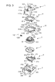
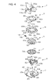
- Fig. 3 and Fig. 4 are disassembled perspective views of the lower case 2 of the rotary electric part 1 and structural members accommodated in the lower case 2 according to the present embodiment.
- Fig. 3 illustrates the lower case 2 and the structural members accommodated in the lower case 2 from above
- Fig. 4 illustrates the lower case 2 and the structural members accommodated in the lower case 2 from below.
- the lower case 2 accommodates a rotating member 6 which accepts rotation operations by an operator, a wafer 7 is integrally formed with this rotating member 6 and having a conducting pattern 702 formed on the lower face thereof, a sliding member 8 disposed facing the lower face of this wafer 7, the slider 9 which is disposed between the rotating member 6 and the movable contact point units 1102 so as to slide in the front-back direction of the rotary electric part 1, a holder 10 which slidably holds the slider 9, and the second terminals 11 having the movable contact point units 1102 capable of moving toward and away from the first terminals 13 in conjunction with the rotational action of the rotating member 6.
- the lower case 2 is formed of an insulating resin material for example, and has a formed generally opened toward the upper side.
- the lower case 2 has a base face portion 201 configured as a generally square horizontal plane, and a side face portion 202 extending toward the upper side from the outer edge portion of the base face portion 201.
- a circular opening 203 is formed at the middle of the base face portion 201.
- a pair of supporting wall portions 204 are formed facing a side face portion 202a disposed toward the back side. These supporting wall portions 204 are erected from the base face portion 201 at a position at a certain distance from the inner wall face of the side face portion 202a.
- Engaging pieces 205 and 206 which respectively engage later-described engaging arms 309 and 310 of the upper case 3, are provided on the outer wall faces of a pair of side wall portions 202b disposed facing the sides and the outer wall face of the side face portion 202a. Further, a holding portion 207 is provided extending vertically at a position toward the back side of the side wall portions 202b disposed to the left side. A through hole passing through in the vertical direction is formed in this holding portion 207, this through hole holding the connecting pin 16 which will be described later. Multiple protruding pieces 208 (three in the present embodiment) are provided on the lower face of the base face portion 201, for positioning as to the parts mounting board. Also, a supporting piece 209 which supports the holder 10 is provided nearby a corner portion of the base face portion 201.
- the sliding member 8 includes, for example, a base portion 801 formed of an insulating resin material, and multiple sliding terminals 802 provided on the base portion 801.
- the sliding terminals 802 are formed by insert molding at the time of manufacturing the base portion 801, for example.
- the sliding member 8 is accommodated in the space within the lower case 2, and is fixed to the base face portion 201.
- the sliding member 8 is fixed to the base face portion 201 by swaging a protruding piece or the like provided protruding downwards from the lower face of the base portion 801.
- the base portion 801 includes a slender portion 801a extending in the left-right direction, and a frame-shaped portion 801b extending toward the back side from around the middle of the slender portion 801a.
- a generally rectangular opening 801c is provided at the middle of the frame-shaped portion 802b.
- the sliding terminals 802 include sliding portions 802a extending slightly upwards from the back side end face of the slender portion 801a, and output portions 802b bent toward the lower side from the front side end face of the slender portions 801a or the inner end face of the frame-shaped portion 801b. The tips of the output portions 802b are guided to the lower side of the lower case 2 in a state fixed to the base face portion 201.
- the rotating member 6 is formed of an insulating resin material, and includes a disc-shaped portion 601 having a general disc shape, a cylindrical portion 602 which extends to the upper side at the middle portion of the disc-shaped portion 601, a holding portion 603 provided extending toward the lower side at the middle portion of the disc-shaped portion 601, and a flange portion 604 provided extending to the sides from the lower end portion of the disc-shaped portion 601.
- a recessed portion 601a is formed on the perimeter face of the disc-shaped portion 601, as an accommodating recessed portion disposed toward the center of the disc-shaped portion 601 (see Fig. 4 ).
- a steel ball 1201 and a coil spring 1202 Accommodated within the recessed portion 601a is a steel ball 1201 and a coil spring 1202 to generate a clicking sensation accompanying rotating operation of the rotating member 6.
- the steel ball 1201 and coil spring 1202 configure part of a moderation mechanism.
- the steel ball 1201 forms an engaging member.
- Multiple crush ribs 603a are provided on the perimeter face of the holding portion 603, to hold the waver 7 (see Fig. 5A ). Detailed configuration of the rotating member 6 will be described later.
- the wafer 7 is configured from an insulating board for example, and has a general disc shape.
- a circular opening 701 is formed at the middle of the wafer 7.
- Multiple conducting patterns 702 (702a, 702b) are provided concentrically around the opening 701 on the lower face of the wafer 7. These conducting patterns 702 configure rotation detecting means to detect rotation (more specifically, rotation angle and rotation position) of the rotating member 6, along with the sliding terminal 802 of the sliding member 8.
- the wafer 7 is integral with the lower face of the flange portion 604 of the rotating member 6.
- the wafer 7 is press-fit at the time of accommodating the holding portion 603 of the rotating member 6 at the opening 701, by crushing the crush ribs 603a disposed on the perimeter face of the holding portion 603, and is fixed to the lower face of the flange portion 604.
- the holder 10 forms a holding member, and is disposed facing the slider 9.
- the holder 10 is formed of an insulating resin material for example, and is configured as a frame-shaped member 1002 in which a generally circular opening 1001 is formed.
- An upper face portion 1003 formed of a smooth face is provided to a part of a pair of side walls 1002a and a back wall 1002b making up the frame-shaped member 1002.
- Guide pieces 1004a and 1004b are disposed on the upper faces of the pair of side walls 1002a, distanced from each other in the front-back direction, to guide the slider 9.
- a pair of guide pieces 1005 extending in the front-back direction are disposed on the upper face of a front wall 1002c, on the inner side of the guide pieces 1004a.
- a recessed portion 1006 which is recessed downwards is provided between the guide pieces 1005. This recessed portion 1006 functions as an opening from which later-described cam portions 613 of the rotating member 6 are exposed.
- a lower face 1007 formed of a smooth face is provided to the lower face of the pair of side walls 1002a, back wall 1002b, and front wall 1002c.
- Click cams 1008 made up of multiple protrusions and recesses are disposed on the inner wall face of the pair of side walls 1002a. These click cams 1008 form a second cam portion.
- the click cams 1008 make up the moderation mechanism along with the steel ball 1201 and coil spring 1202.
- a recessed portion 1009 is provided on the inner wall face of the back wall 1002c. This recessed portion 1009 serves to hold the steel ball 1201 accommodated in the recessed portion 601a of the rotating member 6 in a state where the rotary electric part 1 has not been operated (initial state).
- the click cams 1008 serve to situate the rotating member 6 at a stable position by engaging the steel ball 1201 accommodated in the recessed portion 601a. Specifically, the rotating member 6 is situated at a stable position by engaging the steel ball 1201 resting in a recessed portion making up the click cams 1008.
- the cam portions 613 formed on the disc-shaped portion 601 have a recessed portion 613b thereof situated at a position corresponding to an engaging piece 909 of the slider 9, in a state in which the rotating member 6 is situated at a stable position, which will be described in detail later. That is to say, in a case where the steel ball 1201 has engaged a recessed portion of the click cams 1008, the engaging piece 909 of the slider 9 faces a recessed portion 613b of the cam portions 613.
- the slider 9 makes up a moving member, and is formed of an insulating resin material, for example.
- the slider 9 includes a base 901 having a general plate shape, a guided portion 902 provided to the front side of this base 901, a pair of pressing portions 903 provided to the back side of the base 901, and a contacting portion 904 disposed between the pressing portions 903 toward the back side.
- a generally circular opening 901a is provided to the base 901.
- a lower face portion 905, formed of a smooth face is provided to the lower face of the slider 9.
- the pair of pressing portions 903 are provided protruding further upward than the upper face of the base 901. These pressing portions 903 press upward the movable contact point units 1102 of the later-described second terminals 11, in conjunction with the sliding movement of the slider 9.
- the contacting portion 904 has a contact face 904a intersecting (orthogonally in the present embodiment) the upper face of the base 901.
- the contacting portion 904 receives pressing of a pressing portion 1402 of the later-described lever 14 on the contact face 904a, and transmits the driving force of the lever 14 to the slider 9.
- the detailed configuration of the slider 9 will be described later.
- the second terminals 11 are formed by blanking and bending processing of a metal plate having electroconductivity.
- the second terminals 11 have a terminal portion 1101 generally extending in the vertical direction, and the movable contact point unit 1102 bent around the middle portion of the terminal portion 1101, and extending toward the front side.
- the terminal portions 1101 have at the lower end thereof a pair of inserting portions 1101a to be inserted into the lower case 2, a base 1101b extending vertically slightly behind the inserting portions 1101a, and inserting portions 1101c, provided extending upwards from the middle of the upper end of the base 1101b, and inserted into the board 5.
- the movable contact point units 1102 are formed by being bent forward from the upper end of the bases 1101b.
- the movable contact point unit 1102 have a linking portion 1102a linked to the upper end of the base 1101b, a tongue piece 1102b provided at the tip of the linking portion 1102a, and a contact portion 1102c provided near the tip of the tongue piece 1102b.
- a protruding portion 1102d which protrudes downwards is provided near the tip of the linking portion 1102a.
- the rotary electric part 1 according to the present embodiment has a pair of these second terminals 11, distanced from each other in the left-right direction.
- the movable contact point units 1102 have elasticity.
- FIG. 5 is an explanatory diagram of the rotating member 6 which the rotary electric part 1 according to the present embodiment has.
- Fig. 5 illustrates a frontal view (A of the drawing), a rear view (B of the drawing), and top view (C of the drawing) of the rotating member 6 in the initial state.
- the lower side of Fig. 5C corresponds to the front side of the rotary electric part 1, and the upper side corresponds to the back side of the rotary electric part 1.
- the rotating member 6 has a large-diameter portion 611 and a small-diameter portion 612 (see Fig. 5A and Fig. 5B ).
- the large-diameter portion 611 is disposed to the upper side of the flange portion 604.
- the small-diameter portion 612 is disposed to the upper side of the large-diameter portion 611, except for the front side and back side portions of the rotating member 6.
- Multiple cam portions 613 made up of multiple protruding portions 613a and recessed portions 613b are formed on the perimeter of the small-diameter portion 612 in the circumferential direction (see Fig. 5C ). These cam portions 613 make up of first cam portions.
- the large-diameter portion 611 (611a and 611b) is provided to the same position as the upper end of the cam portions 613.
- the large-diameter portion 611a provided to the front side portion of the rotating member 6 is provided with a recessed portion 614 (see Fig. 5A and Fig. 5C ).
- the engaging piece 909 of the slider 9, described later, is stored in this recessed portion 614 in the initial state.
- the large-diameter portion 611b provided to the back side portion of the rotating member 6 has the above-described recessed portion 601a formed at the lower end thereof (see Fig. 5B ).
- the steel ball 1201 accommodated in this recessed portion 601a is pressed outwards in the radial direction of the disc-shaped portion 601, by the pressing force of the coil spring 1202.
- a rib 615 is provided at a position corresponding to the recessed portion 601a formed on the large-diameter portion 611b, at the back side of the cylindrical portion 602. This rib 615 makes up a third cam portion. The rib 615 protrudes to the back side from the perimeter of the cylindrical portion 602. The rib 615 is configured so as to be capable of coming into contact with a later-described engaging piece 906 of the slider 9, in conjunction with rotating action of the rotating member 6.
- Fig. 6 is an explanatory diagram of the slider 9 included in the rotary electric part 1 according to the present embodiment.
- Fig. 6 illustrates an upper view (A of the drawing), a side view (B in the drawing), and a bottom view (C in the drawing) of the slider 9.
- the lower side of Fig. 6 corresponds to the front side of the rotary electric part 1, and the upper side corresponds to the back side of the rotary electric part 1.
- the guided portion 902 is formed narrower than the base 901.
- a pair of rib-shaped portions 901b are formed on the upper face of the front end of the base 901, protruding slightly upwards (see Fig. 6B ).
- a rib-shaped portion 901c is provided on the upper face of the base 901 so as to extend to extend to the back side, intersecting each of the rib-shaped portions 901b.
- These rib-shaped portions 901b and the rib-shaped portion 901c are used to reinforce the slider 9.
- the rib-shaped portions 901b also contribute to reduced contact noise as to the movable contact point units 1102, which occurs when disengaging the pressing state.
- the portion of the base 901 defining the opening 901a that is toward the back side has provided thereto an engaging piece 906 which protrudes toward the front side and serves as a second engaging portion (see Fig. 6A and Fig. 6C ).
- this engaging piece 906 making up the second engaging portion has a tip with an acute angle (e.g., 60°), and is disposed at a position capable of engaging the aforementioned rib 615 of the rotating member 6 in the initial state.
- protruding holding portions 903a to hold the protruding portions 1102d of the movable contact point units 1102 are provided on the upper faces of the pressing portions 903 toward the front side.
- the holding portions 903a serve to hold the protruding portions 1102d when the slider 9 moves forward in conjunction with the rotation of the rotating member 6 and the movable contact point units 1102 are lifted up, for example.
- Guided portions 907 are provided on the back face of the pressing portions 903.
- the guided portions 907 are formed having a plate thickness generally the same as that of the base 901, and are guided by the guide pieces 1004b of the holder 10.
- a protruding portion 908 is provided between the pair of guided grooves 902b (see Fig. 6C ).
- the protruding portion 908 is provided extending in the left-right direction.
- An engaging piece 909 is provided at the middle of the lower face of the protruding portion 908. This engaging piece 909 forms a first engaging portion.
- the engaging piece 909 has a tip with an acute angle (e.g., 30°), and is formed so as to be capable of engaging/disengaging the cam portions 613 (protruding portions 613a and recessed portions 613b) of the rotating member 6, and at a position so as to be capable of being accommodated in the recessed portion 614.
- Fig. 7 is an explanatory diagram of the positional relationship between the rotating member 6, slider 9, and holder 10 of the rotary electric part 1 according to the present embodiment. Note that Fig. 7 illustrates a state of the rotating member 6, slider 9, and holder 10 where the rotary electric part 1 has not been operated (initial state). Fig. 7 also illustrates the rotating member 6 with the wafer 7 fixed to the flange portion 604.
- the slider 9 has the guided pieces 902a and guided portions 907 held by the holder 10 in a state of being on the inner sides of the respective guide pieces 1004a and 1004b of the holder 10.
- the slider 9 accommodates the guide pieces 1005 of the holder 10 in the guided grooves 902b, and is disposed loaded on the upper face portion 1003 of the holder 10 at the lower face portion 905.
- the engaging piece 909 provided to the guided portion 902 is situated at a position corresponding to the recessed portion 1006 of the holder 10. Accordingly, even in a case where the slider 9 moves by sliding in the front-back direction in conjunction with the rotation of the rotating member 6, the engaging piece 909 does not come into contact with the holder 10.
- the rotating member 6 is disposed in a state where the cylindrical portion 602 passes through the opening 1001 of the holder 10 and the opening 901a of the slider 9.
- the holder 10 has the lower face thereof supported by the supporting piece 209 of the lower case 2, and is disposed on the lower case 2 in a non-contacting state with the flange portion 604 of the rotating member 6 and so forth. Accordingly, the holder 10 does not impede rotating actions of the rotating member 6.
- the slider 9 In the initial state, the slider 9 is disposed at a position on the holder 10 farthest to the back side. In this state, the engaging piece 909 of the slider 9 is in a state accommodated in the recessed portion 614 formed in the disc-shaped portion 601 of the rotating member 6.
- the engaging piece 906 of the slider 9 is disposed such that the tip (front end) thereof faces the tip (back end) of the rib 615 provided on the cylindrical portion 602 of the rotating member 6.
- the guide pieces 1004b of the holder 10 function as stoppers which come into contact with the rear faces of the pressing portions 903 of the slider 9.
- FIG. 8 and Fig. 9 are disassembled perspective views of the upper case 3 and cover 4 of the rotary electric part 1 according to the present embodiment, and the structural members accommodated therein.
- Fig. 8 illustrates the upper case 3 and cover 4 and the structural members accommodated therein from the upper side
- Fig. 9 illustrates the upper case 3 and cover 4 and the structural members accommodated therein from the lower side.
- the upper case 3 accommodates the pair of first terminals 13 which can conduct with the second terminals 11, and the lever 14.
- the cover 4 accommodates the solenoid 15.
- the board 5 is disposed between the upper case 3 and cover 4.
- the board 5 is placed on a portion of the upper case 3 at the back side, and the cover 4 is placed thereupon.
- the cover 4 is fixed to the upper case 3 with the board 5 sandwiched therebetween, whereby the board 5 is also in a state fixed to the upper case 3.
- the upper case 3 is formed of an insulating resin material for example, and has a shape generally opened downwards.
- the upper case 3 has a ceiling portion 301 having a rectangular shape in plane view, and a side face portion 302 provided extending downwards from the edges of the ceiling portion 301.
- the ceiling portion 301 is provided with a terminal placement portion 303 provided to the front side, and a board placement portion 304 provided to the back side.
- the board placement portion 304 is disposed at a higher position than the terminal placement portion 303.
- a terminal accommodating portion 305 having a generally rectangular shape in plane view is provided at the middle of the terminal placement portion 303.
- the terminal accommodating portion 305 is provided extending upwards from the terminal placement portion 303 and has a configuration opening upwards.
- the upper ends of the first terminals 13 (later-described terminal portions 1302) inserted from the lower side are accommodated within the terminal accommodating portion 305. Note that the upper ends of the first terminals 13 are accommodated within the terminal accommodating portion 305, and do not protrude farther upwards than the terminal accommodating portion 305.
- a supporting face 306 formed of a smooth face supporting the lower face of the board 5 is provided at the middle of the board placement portion 304.
- a circular opening 306a is formed at the middle of the supporting face 306.
- a later-described plunger 1503 of the solenoid 15 is inserted through this opening 306a.
- a pair of fixing walls 307 are provided protruding upwards at the back end of the supporting face 306. These fixing walls 307 are used to position the board 5 placed on the supporting face 306.
- a pair of engaging arms 308 which extend upwards are provided at the front end of the board placement portion 304. These engaging arms 308 serve to engage later-described engaging pieces 403 of the cover 4 so that the cover 4 is fixed to the upper case 3.
- These engaging arms 308 are configured so as to be capable of snap joining to the engaging pieces 403.
- Engaging arms 309 are disposed extending downwards from the front end of side face portions 302a disposed on the left and right in directions facing each other.
- an engaging arm 310 is disposed extending downwards from the middle of a side face portion 302b situated at the back side.
- These engaging arms 309 and 310 serve to engage engaging pieces 205 and 206 of the lower case 2 respectively, so as to fix the upper case 3 to the lower case 2.
- These engaging arms 309 and 310 are configured so as to be capable of snap joining to the engaging pieces 205 and 206.
- a pair of extending portions 311 are disposed to the side of the engaging arm 310 extending downwards from the side face portion 302b (see Fig. 9 ). These extending portions 311 serve to enter between the side face portion 202a and the supporting wall portions 204 of the lower case 2 so as to restrict movement of the second terminals 11.
- Engaging pieces 312 and 313 are provided on the outer wall face at the back side of the side face portion 302a and the outer wall face at the left side of the side face portion 302b, to engage later-described engaging arms 404 and 405 of the cover 4.
- a slit 314 is formed extending vertically, at the front side of the engaging piece 312 of the side face portion 302a. This slit 314 accommodates a part of the later-described connecting pin 16. The configuration of the inner side (lower face side) of the upper case 3 will be described later.
- the pair of first terminals 13 are each formed by blanking and bending processing of a metal plate having electroconductivity.
- the first terminals 13 have a base 1301 having a generally flat plate shape, and a terminal portion 1302 provided extending upwards from a part of the edge of the base 1301.
- a contact point portion 1303 is provided on the end of the base 1301.
- the first terminals 13 have the terminal portions 1302 thereof inserted through unshown slits formed at the lower face of the terminal accommodating portion 305 of the upper case 3 so as to be fixed.
- the lever 14 makes up a driving member, and is formed of an insulating resin material, for example.
- the lever 14 includes a shaft portion 1401 extending on the left-right direction, a pressing portion 1402 extending downwards from the shaft portion 1401, and an engaging portion 1403 extending obliquely downwards toward the back side form the shaft portion 1401.
- the shaft portion 1401 of the lever 14 is supported by a later-described supporting piece 316 of the upper case 3, which will be described later in more detail.
- the pressing portion 1402 is situated at a position capable of coming into contact with the contact face 904a of the contacting portion 904 of the slider 9, in a state of being supported by the upper case 3.
- the engaging portion 1403 is situated at a position capable of engaging a part of the later-described plunger 1503 of the solenoid 15, in a state of being supported by the upper case 3.
- the solenoid 15 has a case 1502 where a coil 1501 is accommodated, the plunger 1503 disposed so as to be capable of reciprocal movement in the vertical direction of the ceiling rotary electric part 1 (axial line direction of the rotating member 6), and a coil spring 1504 disposed between a base face portion 1502a of the case 1502 and the plunger 1503.
- a circular opening 1502b is formed at the middle of the base face portion 1502a of the case 1502.
- a pair of positioning pieces 1502c is formed at the back side of this opening 1502b.
- a pair of connecting terminals 1502d is provided at the front face portion of the base face portion 1502a, extending downwards.
- the connecting terminals 1502d are terminal electrically connected to the ends of the coil 1501, for conducting electricity to the coil 1501. Note that in the present embodiment, an AC solenoid is used as the solenoid 15.
- the plunger 1503 has a main unit 1503a contained in a part of a wound portion of the coil 1501 through the opening 1502b, a shaft 1503b provided protruding downwards from this main unit 1503a, and a flange portion 1503c provided at the lower end of the main unit 1503a.
- the outer diameter of the main unit 1503a is smaller than the inner diameter dimensions of the coil spring 1504.
- An engaging portion 1503d having a disc shape is disposed at the tip (lower end) of the shaft 1503b.
- the outer diameter of the flange portion 1503c is formed larger than the outer dimensions of the coil spring 1504.
- the coil spring 1504 is disposed between the case 1502 and the flange portion 1503c of the plunger 1503 in a state of having been inserted through the main unit 1503a of the plunger 1503.
- the lower end of the coil spring 1504 is retained by the upper face of the flange portion 1503c, and the upper end of the coil spring 1504 is retained by the lower face of the base face portion 1502a of the case 1502 (or more specifically, the lower face around the opening 1502b).
- the coil spring 1504 provides pressing force pressing the plunger 1503 downwards.
- the board 5 is formed of an insulating board for example, and has a generally rectangular shape in plane view.
- a circular opening 501 is formed at the middle of the board 5.
- the plunger 1503 of the solenoid 15 passes through this opening 501.
- a pair of positioning holes 502 are formed at the back of the opening 501.
- a pair of slits 503 is formed on the outer side of these positioning holes 502, from the back end face toward the front side.
- the fixing walls 307 of the upper case 3 are disposed on these slits 503.
- a pair of second terminal connecting holes 504 where the second terminals 11 are connected is formed on the outer sides of the slits 503.
- a pair of solenoid connecting holes 505 where the connecting terminals 1502d of the solenoid 15 are connected is formed to the front side of the opening 501.
- a pin connection hole 506 where the connecting pin 16 is connected is formed nearby the left side end of the board 5.
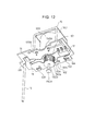
- a triac 17 which switches (on/off control) current, and multiple (two in the present embodiment) resistor elements 18 are mounted on the lower face of the board 5.
- a lead pattern is formed on the upper face of the board 5, for connecting one second terminal connecting hole 504 and one solenoid connecting hole 505.
- Provided on the lower face of the board 5 are a lead pattern for connecting the pin connection hole 506 and a connection terminal of the triac 17 via a resistor 18, and a lead pattern for connecting the other solenoid connecting hole 505 and the connection terminal of the triac 17 (see Fig. 12 ).
- the cover 4 is confirmed of an insulating resin material for example, and has a shape opened generally downwards.
- the cover 4 has a ceiling portion 401 having a rectangular shape in plane view, and a side face portion 402 provided extending downwards from the edges of the ceiling portion 401.
- a side face portion 402a disposed at the front side is provided with a pair of engaging pieces 403 which engage the engaging arms 308 of the upper case 3.
- Engaging arms 404 and 405 are provided extending downwards at the back end of a side face portion 402b disposed to the left side, and at the right end of a side face portion 402c disposed at the back end.
- These engaging arms 404 and 405 are configured so as to be capable of engaging the respective engaging pieces 312 and 313 provided on the upper case 3.
- the engaging arms 404 and 405 are configured so as to be capable of snap joining to the engaging pieces 312 and 313.
- Fig. 10 is an explanatory diagram of the configuration of the inner side (lower face side) of the upper case 3 which the rotary electric part 1 according to the present embodiment has. Note that the upper case 3 is illustrated vertically inverted in Fig. 10 . Also note that Fig. 10 illustrates the upper case 3 in a state where the first terminals 13 and lever 14 have been affixed.
- a pair of holding pieces 315 extending downwards from the lower face of the board placement portion 304, and a pair of supporting pieces 316 provided to the sides of the holding pieces 315.
- the holding pieces 315 have a U-shaped form opening downwards (toward the upper side in Fig. 10 ) at the tips (lower ends) thereof.
- the supporting pieces 316 have hook portions 316a formed on the inner sides of the tips, protruding inwards.
- the holding pieces 315 and the supporting pieces 316 are provided to support the lever 14.
- the lever 14 is supported from the sides by the hook portions 316a of the supporting pieces 316, in a state of the shaft portion 1401 being accommodated in the opening portions of the holding pieces 315. In a state thus supported, the lever 14 is held turnably within a predetermined range, with the center of the shaft 1401 as the center of turning.
- the tip of the engaging portion 1403 of the lever 14 branches into two, this portion being disposed at a position facing the opening 306a.
- the engaging portion 1403 is configured so as to accommodate the shaft 1503b of the solenoid 15 with this branched portion, and also so as to be capable of engaging the engaging portion 1503d.
- a storing portion 317 which turnably accommodates the tip (upper end) of the cylindrical portion 602 of the rotating member 6 in a state where the rotary electric part 1 has been assembled, is provided at the front side of the holding pieces 315 and supporting pieces 316.
- a partition 318 extending downwards from the lower face of the board placement portion 304 is disposed to the front side of this storing portion 317. This partition 318 serves to section off the space where the bases 1301 of the first terminals 13 are disposed.
- the pair of first terminals 13 are fixed to the upper case 3 in a state where the contact point portions 1303 are exposed downwards in this space sectioned off by the partition 318.
- Fig. 11 and Fig. 12 are perspective diagrams for describing the structural members around the board 5 which the rotary electric part 1 according to the present embodiment has.
- Fig. 11 illustrates the solenoid 15 mounted on the board 5, and the second terminals 11 and connecting pin 16 connected to the board 5.
- Fig. 12 illustrates the solenoid 15, triac 17, and resistor elements 18 mounted on the board 5, and the connecting pin 16 connected to the board 5.
- the solenoid 15 is mounted on the upper face of the board 5 in a state with the positioning pieces 1502c inserted through the positioning holes 502, and the connecting terminals 1502d inserted through the solenoid connecting holes 505.
- the plunger 1503 making up the solenoid 15 protrudes downwards through the opening 501 in the board 5.
- the coil spring 1504 is disposed around the plunger 1503, applying pressing force against the upper face of the flange portion 1503c.
- the inserting portions 1101c of the second terminals 11 are inserted through the second terminal connecting holes 504.
- One (left-side) second terminal 11 is connected to one (left-side) connecting terminal 1502d of the solenoid 15 via the lead pattern formed on the upper face of the board 5.
- the other (right-side) second terminal 11 is connected to the other (right-side) connecting terminal 1502d of the solenoid 15 via the lead pattern formed on the upper face of the board 5 and the triac 17.
- the upper end of the connecting pin 16 is inserted through the pin connection hole 506.
- the connecting pin 16 is connected to the triac 17 via the lead pattern formed on the lower face of the board 5 and the resistor elements 18.
- connecting terminals 1502d, inserting portions 1101c, and connecting pin 16 are respectively inserted through the solenoid connecting holes 505, second terminal connecting holes 504, and pin connection hole 506 of the board 5, and soldered to soldering lands provided around the connecting holes 504 through 506, but the soldering has been omitted from illustration in Fig. 11 , Fig. 12 , and so forth, for to facilitate description.
- the triac 17 and resistor elements 18 are also mounted by soldering to predetermined positions on the board 5.
- the rotary electric part 1 drives the solenoid 15 by supplying drive instruction signals (predetermined voltage) via the connecting pin 16, in an on state (state where the first terminals 13 and second terminals 11 are conducting). Accordingly, the slider 9 is moved by driving the lever 14 engaging the plunger 1503, thus switching to a power off state (auto-off function). Details of this auto-off function will be described later.
- FIG. 13 is a cross-sectional view illustrating an assembled state of the rotary electric part 1 according to the present embodiment.
- Fig. 14 and Fig. 15 respectively are a perspective view and side view illustrating the assembled state of the rotary electric part 1 according to the present embodiment.
- Fig. 13 through Fig. 15 illustrate a state in which the rotary electric part 1 has not been operated (initial state).
- Fig. 13 illustrates a cross-section passing through the center of the cylindrical portion 602 of the rotating member 6 and the plunger 1503 of the solenoid 15.
- the upper case 3 has been omitted from illustration in Fig. 14 and Fig. 15 to facilitate description.
- the sliding member 8 is disposed on the base face portion 201 of the lower case 2 within the rotary electric part 1, with the output portions 802b of the sliding terminals 802 extending downwards from the lower case 2.
- the wafer 7, integrated with the flange portion 604 of the rotating member 6, is disposed above the sliding member 8 so as to face the sliding member 8.
- the sliding portions 802a of the sliding terminals 802 are slidably disposed on the conducting pattern 702 provided on the lower face of the wafer 7.
- the holder 10 is disposed so as to enclose the disc-shaped portion 601 of the rotating member 6.
- the holder 10 is placed upon the supporting piece 209 (omitted from illustration in Fig. 13 ) provided to the lower face of the lower case 2, and does not come into contact with the rotating member 6.
- the steel ball 1201 accommodated in the recessed portion 601a of the disc-shaped portion 601 is pressed to the back side by the pressing force of the coil spring 1202, and is accommodated in the recessed portion 1009 formed at the inner wall face of the holder 10.
- the slider 9 is disposed above the holder 10, so as to be movable by sliding in the front-back direction.
- the upper case 3 is placed upon the lower case 2 accommodating these structural members.
- the upper case 3 is placed thereupon, in a state accommodating the tip (upper end) of the cylindrical portion 602 of the rotating member 6 at the storing portion 317 formed on the lower face thereof.
- the first terminals 13 fixed to the upper case 3 are disposed with a certain spacing therebetween in the front-back direction in the terminal accommodating portion 305.
- the board 5 on which the solenoid 15 has been mounted is disposed at the back side the upper face of this upper case 3 (board placement portion 304).
- the solenoid 15 is disposed in a state where the plunger 1503 is protruding into the space within the upper case 3.
- the cover 4 is placed upon the board 5 so as to accommodate the solenoid 15 mounted on the board 5, and is attached to the upper case 3.
- the lever 14 supported by the upper case 3 accommodates part of the shaft 1503b of the plunger 1503 by the engaging portion 1403 thereof, and is disposed at a position such that the pressing portion 1402 is distanced from the contact face 904a of the slider 9.
- the movable contact point units 1102 of the second terminals 11 are disposed above the slider 9 accommodated in the lower case 2.
- the slider 9 is situated at a position farthest to the back side on the holder 10.
- the protruding portions 1102d of the movable contact point units 1102 are situated at positions to the front of the pressing portions 903.
- the tongue pieces 1102b of the movable contact point units 1102 are situated above the rib-shaped portions 901b provided to the base 901 of the slider 9, with the contact portions 1102c distanced from the contact point portions 1303 of the first terminals 13. While the protruding portions 1102d are disposed at positions not making contact with the upper face of the base 901, a configuration may be made with these in contact.
- the engaging piece 906 of the slider 9 is disposed facing the rib 615 provided to the cylindrical portion 602 of the rotating member 6.
- the tip of the rib 615 is disposed facing the tip of the engaging piece 906, in a non-contact state.
- the engaging piece 909 of the slider 9 is accommodated in the recessed portion 614 provided to the disc-shaped portion 601 of the rotating member 6.
- the rotary electric part 1 according to the present embodiment which has the above-described configuration can be switched to a power-on state by rotational operation of the rotating member 6 from the initial state (manual on), and switched to a power-off state by rotational operation of the rotating member 6 from the power-on state (state where the first terminals 13 and second terminals 11 are not conducting) (manual off). Further, the rotary electric part 1 according to the present embodiment can be switched to a power-off state from the power-on state by the solenoid 15 being driven under certain conditions (auto off), and switched to a power-on state by rotational operation of the rotating member 6 from the auto-off state (manual on after auto off).
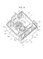
- Fig. 16 and Fig. 17 respectively are a perspective view and side view of the rotary electric part 1 according to the present embodiment at the time of a manual on operation. Note that the upper case 3 is omitted from illustration in Fig. 16 and Fig. 17 , in the same way as with Fig. 14 and Fig. 15 . This is also true of the perspective views and side views of the rotary electric part 1 in Fig. 18 and subsequent drawings as well.
- the entire movable contact point units 1102 are lifted upwards, and the protruding portions 1102d are placed upon the pressing portions 903, whereupon the contact portions 1102c provided on the tongue pieces 1102b come into contact with the contact point portions 1303 of the first terminals 13. Accordingly, the first terminals 13 and second terminals 11 are switched to a conducting state (power-on state by manual on operation).
- the engaging piece 906 moves forward in conjunction with the sliding movement of the slider 9, and is in a state placed in the rotational movement region of the rib 615.
- the rib 615 has moved from the position facing the engaging piece 906 to a different position, in accordance with the rotating operation of the rotating member 6, and thus does not come into contact with the engaging piece 906.
- the contacting portion 904 of the slider 9 has the contact face 904a thereof situated near the rear face of the pressing portion 1402 of the lever 14.
- the rotating member 6 regarding which the rotating operation has been performed is in a state of being placed at a stable position, by engaging of the steel ball 1201 accommodated in the recessed portion 601a and the click cams 1008 (recessed portions) of the holder 10.
- the first terminals 13 and second terminals 11 of the rotary electric part 1 according to the present embodiment can thus be switched to a conducting state by moving in a sliding manner the slider 9 in a direction intersecting the rotational axis line direction of the rotating member 6 (a direction orthogonal to the rotational axis line direction in the present embodiment) in conjunction with the rotating operation as to the rotating member 6.
- the slider 9 is disposed between the rotating member 6 and the movable contact point units 1102. Accordingly, a situation where the rotation of the rotating member 6 is directly transmitted to the movable contact point units 1102 can be prevented, so the contact stability of the movable contact point units 1102 as to the first terminals 13 can be improved.
- the slider 9 is held so as to be capable of sliding movement by the holder 10, so movement of the slider 9 in the front-back direction of the rotary electric part 1 (direction orthogonal to the axial line direction of the rotating member 6) can be performed smoothly.
- the slider 9 includes a base 901 and pressing portions 903 which are provided protruding farther to the movable contact point units 1102 side than the base 901.
- the movable contact point units 1102 have protruding portions 1102d protruding to the slider 9 side, so that in a case where the first terminals 13 and second terminals 11 are in a conducting state, the pressing portions 903 are in contact with the protruding portions 1102d so as to press the movable contact point units 1102d toward the side of the first terminals 13.
- the contact point units 1102 come into contact with the protruding portions 1102d by the pressing portions 903 so as to be pressed toward the side of the first terminals 13, so switching of the first terminals 13 and the second terminals 11 to a conducting state can be performed in a stable manner, without having a complicated configuration.
- the rotary electric part 1 has holding portions 903a which hold the protruding portions 1102d of the movable contact point units 1102 formed at the upper faces of the pressing portions 903 of the slider 9, at the front side ends.
- the slider 9 has a configuration such that, at the time of the protruding portions 1102d riding up over the holding portions 903a, the slider 9 slightly moves forward by itself due to the elastic recovery force of the movable contact point units 1102, so the protruding portions 1102d of the movable contact point units 1102 in a state of being pressed by the pressing portions 903 can be held in a more stable manner by the holding portions 903a. Accordingly, trouble such as the protruding portions 1102d moving away from the pressing portions 903 due to vibration or the like and the conducting state of the first terminals 13 and the second terminals 11 switching to a non-conducting state, can be suppressed.
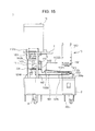
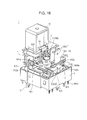
- Fig. 18 is a perspective view illustrating the state of the rotary electric part 1 according to the present embodiment immediately prior to a manual off operation. Note that part of the front side of the movable contact point units 1102 has been omitted from illustration in Fig. 18 for the sake of facilitating description.
- the rotating member 6 being rotated from the power on state illustrated in Fig. 16 to return to the initial state (i.e., upon the rotating member 6 being rotationally operated until the rib 615 is at a position facing the engaging piece 906 of the slider 9), the rib 615 comes into contact with the engaging piece 906, since the engaging piece 906 is situated in the rotating movement path of the rib 615.
- the engaging piece 906 is pressed to the back side by the rotating member 6 and as a result the entire slider 9 moves by sliding to the back side, to the position illustrated in Fig. 14 and Fig. 15 .
- the movable contact point units 1102 move downwards due to the pressing of the pressing portions 903 as to the protruding portions 1102d being disengaged, and the contact portions 1102c provided on the tongue pieces 1102b are distanced from the contact point portions 1303 of the first terminals 13 (power-off state by manual off operation).
- the rotary electric part 1 is provided with the engaging piece 906 at a position facing the engaging piece 909 of the slider 9 across the rotational axis line of the rotating member 6, and on the other hand, is provided with the rib 615 on the rotating member 6 which engages with the engaging piece 906 in conjunction with rotation of the rotating member 6 and causes the slider 9 to return to the initial position. Accordingly, the rib 615 engages the engaging piece 906 upon rotation of the rotating member 6, whereby the slider 9 can be returned to the initial position, so the first terminals 13 and second terminals 11 can be switched to a non-conducting state in a sure manner by an operator making a rotating operation of the rotating member 6 as to the initial position.
- the rotary electric part 1 has an auto off function to switch to a power off state from the power on state, by driving the solenoid 15 under certain conditions.
- the solenoid 15 is driven according to driving instruction signals output from a control unit of a device (e.g., a washing machine) in which the rotary electric part 1 is installed.
- the driving instruction signals are output in a case where a situation is detected that there has been no operation from the operator for a predetermined amount of time, or completion of a specified action has been completed.
- Fig. 19 is a diagram illustrating an example of circuit diagrams relating to the auto off function which the rotary electric part 1 according to the present embodiment has. Members which are in common with the structural members used in the description above are denoted with the same reference numerals in the circuit diagrams illustrated in Fig. 19 , and description thereof will be omitted.
- Fig. 19A illustrates a circuit diagram in a power on state
- Fig. 19B illustrates a circuit diagram in a power off state, switched from the power on state by the auto off function.
- the pair of resistor elements 18A and 18B are serially connected to the connecting pin 16 connected to the parts mounting board.
- the gate of the triac 17 is connected to the node of the resistor element 18A and resistor element 18B.
- Connected to one electrode of the triac 17 is the solenoid 15 (coil 1501).
- the other end of the solenoid 15 (coil 1501) is connected to one second terminal 11.
- the end of the resistor element 18B not connected to the resistor element 18A is connected to the other second terminal 11 and the other electrode of the triac 17.
- Connected to these second terminals 11 are the pair of first terminals 13, via the power switch made up of the movable contact point units 1102. Note that AC power voltage (e.g., 200 V) is applied (supplied)to the pair of second terminals 11.
- the triac 17 In the power on state, the triac 17 is in an off state, and the first terminals 13 and second terminals 11 are in a conducting state by the movable contact point units 1102 as illustrated in Fig. 19A .
- a driving instruction signal predetermined voltage
- the triac 17 switches to an on state, and driving current flows to the solenoid 15 (coil 1501) via the triac 17.
- the solenoid 15 Upon the solenoid 15 being driven by this driving current, the conducting state of the first terminals 13 and second terminals 11 by the movable contact point units 1102 is switched to a non-conducting state.
- supply of the power voltage to the first terminals 13 via the second terminals 11 is cut off.
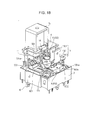
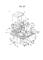
- Fig. 20 and Fig. 21 respectively are a perspective view and side view of the rotary electric part 1 according to the present embodiment at the time of an auto off operation.
- the solenoid 15 Upon a driving instruction signal being input via the connecting pin 16 from the power on state under certain conditions, the solenoid 15 is driven. Accordingly, at the solenoid 15, the plunger 1503 serving as a moving core is drawn upwards against the pressing force of the coil spring 1504.
- the engaging portion 1503d provided at the tip of the plunger 1503 engages the engaging portion 1403 of the lever 14. Accordingly, when the engaging portion 1403 is drawn upwards in conjunction with the upward movement of the plunger 1503, the lever 14 turns with the axial center of the shaft portion 1401 as the fulcrum of turning.
- the pressing portion 1402 presses the contacting portion 904 by coming into contact with the contact face 904a provided on the contacting portion 904 of the slider 9. Accordingly, the contacting portion 904 presses the lever 14 further backwards, and as a result, the entire slider 9 moves backwards as illustrated in Fig. 20 and Fig. 21 .
- the pressing portions 903 moves backwards from beneath the protruding portions 1102d of the movable contact point units 1102 in conjunction with the sliding movement of the slider 9.
- the entire movable contact point units 1102 move downwards by elastic recovery force, whereupon the contact portions 1102c provided on the tongue pieces 1102b are distanced from the contact point portions 1303 of the first terminals 13. Accordingly, the first terminals 13 and second terminals 11 are switched to a non-conducting state (power-off state by auto off operation).
- the engaging piece 906 moves to the back side in conjunction with the sliding movement of the slider 9, and thus is a state evacuated from the rotational movement region of the rib 615. Also, in a state where the rotating member 6 is situated at a stable position as described above, a recessed portion 613b of the cam portions 613 is situated at a position facing the engaging piece 909 of the slider 9. Accordingly, the engaging piece 909 is accommodated in a recessed portion 613b of the cam portions 613 provided to the disc-shaped portion 601 of the rotating member 6, by the sliding movement of the slider 9.
- the first terminals 13 and second terminal 11 in a conducting state can be returned to a non-conducting state by disengaging the contact between the movable contact point units 1102 and the first terminals 13, by the recovery mechanism including the solenoid 15 and lever 14. Accordingly, by controlling power to the solenoid 15, the conducting state between the first terminals 13 and the second terminals 11 can be switched to a non-conducting state without necessitating rotation by the rotating member 6. As a result, a state can be avoided where standby current continues to be supplied in an application of the rotary electric part 1 to a power switch of a washing machine or the like, thereby enabling demand for reduction in power consumption to be met.
- the first terminals 13 and second terminals 11 are each provided in pairs, and the movable contact point units 1102 provided to the pair of second terminals 11 are disposed arrayed in the left-right direction across the rotational axis line of the rotating member 6.
- the slider 9 has a pair of pressing portions 903 corresponding to the movable contact point units 1102 of the pair of second terminals 11, and has a configuration where the contacting portion 904 situated between the pair of pressing portions 903 is pressed by the lever 14.
- the contacting portion 904 (more specifically, the contact face 904a) situated between the pair of pressing portions 903 receives pressing force from the lever 14, so the slider 9 can be returned smoothly, and the first terminals 13 and second terminals 11 can be switched to a non-conducting state in a stable manner.
- the solenoid 15 has the plunger 1503 which is reciprocally movable in the vertical direction
- the lever 14 has the shaft portion 1401, pressing portion 1402 which presses the slider 9, and the engaging portion 1403 which engages the plunger 1503, with the shaft portion 1401 held turnably by the upper case 3. Accordingly, the pressing portion 1402 of the lever 14 can be smoothly moved according to driving by the solenoid 15, and the slider 9 can be returned to the initial position in a sure manner.
- Fig. 22 and Fig. 23 respectively are a perspective view and a side view of the rotary electric part 1 according to the present embodiment after an auto off operation.
- the solenoid 15 Upon the driving instruction signal output via the connecting pin 16 stopping, the solenoid 15 returns to the initial state.
- the plunger 1503 of the solenoid 15 moves downwards in accordance with the pressing force of the coil spring 1504.
- the lever 14 returns to the initial position illustrated in Fig. 22 and Fig. 23 in conjunction with the movement of the plunger 1503.
- the slider 9 is in a state where the pressing portions 903 are retained by the protruding portions 1102d of the movable contact point units 1102, and accordingly does not move forward.
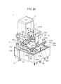
- Fig. 24 is a perspective view of the rotary electric part 1 according to the present embodiment at the time of a manual on operation after an auto off operation.
- a protruding portion 613a (more specifically, the wall face portion defining the protruding portion 613a) comes into contact with the engaging piece 909 which had been accommodated in a recessed portion 613b of a cam portion 613. Accordingly, the engaging piece 909 is pressed toward the front side by the rotating member 6, and as a result, the entire slider 9 moves forward by sliding, as illustrated in Fig. 24 .
- the pressing portions 903 press the protruding portions 1102d of the movable contact point units 1102 upwards. Accordingly, the entire movable contact point units 1102 are raised up, and the protruding portions 1102d are placed upon the pressing portions 903, whereby the contact portions 1102c provided on the tongue pieces 1102b come into contact with the contact point portions 1303 of the first terminals 13. Accordingly, the first terminals 13 and second terminals 11 are switched to a conducting state. That is to say, the rotary electric part 1 according to the present embodiment is capable of returning to an on state by performing a rotating operation of the rotating member 6 after the auto off function has been executed.
- first cam portions 613 made up of multiple recessed portions 613b and protruding portions 613a are provided on the rotating member 6.
- the protruding portions 613a of the first cam portions 613 engage the engaging piece 909 of the slider 9 in conjunction with the rotations of the rotating member 6 so as to move the slider 9, and the movable contact point units 1102 (contact portions 1102c) come into contact with the first terminals 13 (contact point portions 1303).
- the slider 9 can be moved to multiple positions in conjunction with the rotations of the rotating member 6, so even in a case where the first terminals 13 and the second terminals 11 have been switched to a non-conducting state at a position other than the initial position by the recovery mechanism, these can be returned to a conducting state in a short period, i.e., by few rotational operations of the rotating member 6.
- the protruding portions 1102d are configured from a part of the movable contact point units 1102 is described in the above embodiment.
- the configuration of the protruding portions 1102d is not restricted thusly, and various modifications may be made.
- a function the same as that of the protruding portions 1102d may be had by fixing protrusions of synthetic resin or the like, for example, to the movable contact point units 1102.
- the slider 9 has a plate-shaped base 901 and pressing portions 903 protruding upwards from this base 901 is described in the above embodiment.
- the configuration of the slider 9 is not restricted thusly, and various modifications may be made.
- a configuration may be made where the overall slider 9 may be formed having thickness dimensions equivalent to that of the pressing portions 903 according to the present embodiment, while recessed portions are formed at positions corresponding to the base 901 according to the present embodiment.
- the slider 9 moves in a direction orthogonal to the rotational axis line direction of the rotating member 6 in conjunction with rotations of the rotating member 6 is described in the above embodiment.
- the direction of movement of the slider 9 is not restricted thusly.
- the slider 9 may move in a direction intersecting the rotational axis line direction of the rotating member 6 at an 80° angle, for example.
- a steel ball 1201 is used as an engaging member for engaging/disengaging the click cams 1008 serving as the second cam portion is described in the above embodiment.
- the engaging member is not restricted to a steel ball, and various modifications may be made.
- a synthetic resin sphere may be used as the engaging member. Further, this is not restricted to a sphere, and a pin-shaped engaging member with a curved face formed on the tip may be used.
Landscapes
- Rotary Switch, Piano Key Switch, And Lever Switch (AREA)
Abstract
Description
- The present invention relates to a rotary electric part, and more particularly relates to a rotary electric part suitably used as a rotary encoder to detect a rotational angle, rotational direction, and so forth, of a rotating member, in accordance with rotation operations thereof, and so forth.
- Conventionally, there has been proposed a rotary electric part including a rotating member rotatably held within a casing, and a contact point mechanism having a moving contact unit whereby a conducting state and non-conducting state are switched between terminals, according to a rotated position of the rotating member, so as to switch between a conducting state and non-conducting state between the terminals in accordance with a rotating operation as to the rotating member (for example, PTL 1).
- PTL 1: Japanese Unexamined Patent Application Publication No.
2009-16247 - However, the above-described rotary electric part cannot switch a conducting state between terminals to a non-conducting state unless the rotating member is rotated. Accordingly, in a case of using this rotary electric part as a power switch for a washing machine or the like, for example, there may be a situation occurring where current such as standby current continues to be supplied even after washing has ended.
- The present invention has been made in light of this state, and accordingly it is an object thereof to provide a rotary electric part which can switch a conducting state between terminals to a non-conducting state without rotating the rotating member.
- A rotary electric part according to the present invention includes: a casing from which a first terminal is exposed; a rotating member rotatably held within the casing; a second terminal having a movable contact point unit capable of contacting and separating from the first terminal in conjunction with rotating actions of the rotating member; and rotation detecting means that detect rotation of the rotating member; in which a conducting state and a non-conducting state, between the first terminal and the second terminal, is switched, wherein a moving member is provided between the rotating member and the movable contact point unit, the moving member moving in a direction intersecting a rotational axis line direction of the rotating member in conjunction with rotation of the rotating member, and bringing the movable contact point unit into contact with the first terminal, and further, recovery mechanism is provided to disengage contact between the movable contact point unit and the first terminal and restore the first terminal and the second terminal in a conducting state to a non-conducting state, the recovery mechanism including a solenoid, and a driving member which is driven by the solenoid and returns the moving member.
- According to this rotary electric part, the first terminal and second terminal in a conducting state can be returned to a non-conducting state by disengaging the contact between the contact point unit and the first terminal, by the recovery mechanism including the driving member to return the solenoid and moving member. Accordingly, by controlling power to the solenoid, the conducting state between the first terminal and the second terminal can be switched to a non-conducting state without necessitating rotation by the rotating member. As a result, a state can be avoided where standby current continues to be supplied in a case of applying the rotary electric part to a power switch of a washing machine or the like, thereby enabling demand for reduction in power consumption to be met. Also, the moving member is disposed between the rotating member and movable contact point unit, so a situation where the rotation of the rotating member is directly transmitted to the contact point unit can be prevented, and accordingly the contact stability of the contact point unit as to the first terminal can be improved.
- For example, in the rotary electric part, the moving member further includes a base, and a pressing portion protruding further toward the movable contact point unit side than the base, in which the movable contact point unit has a protruding portion protruding toward the side of the moving member, wherein, in a state of the first terminal and second terminal being in a conducting state, the pressing portion is in contact with the protruding portion and presses the movable contact point unit toward the first terminal side. In this case, in a case where the first terminal and second terminal are in a conducting state, the movable contact point unit is in contact with the protruding portion by the pressing portion provided on the moving member so as to be pressed toward the side of the first terminal, so switching of the first terminal and the second terminal to a conducting state can be performed in a stable manner, without having a complicated configuration.
- Particularly, in the rotary electric part, the protruding portion is preferably pressed toward the first terminal side by the pressing portion, in conjunction with the movement of the moving member in one direction, with a protrusion-shaped holding portion which holds the protruding portion of the movable contact point unit being provided on an end of the pressing portion in the one direction. In this case, the protrusion of the movable contact point unit is held in a stable manner by the holding portion provided on the pressing portion, so trouble such as the protruding portion moving away from the pressing portion due to vibration or the like, and the conducting state of the first terminal and the second terminal switching to a non-conducting state, can be suppressed.
- Also, in the rotary electric part, preferably, a plurality of first cam portions made up of a plurality of recessed portions and protruding portions are provided on the rotating member in the circumferential direction, and, in conjunction with rotation of the rotating member, the protruding portions of the first cam portions engage a first engaging portion provided on the moving member to move the moving member in a direction intersecting the rotational axis line direction of the rotating member, and also to bring the moveable contact point unit into contact with the first terminal. In this case, the multiple protruding portions provided in the circumferential direction of the rotating member engage the first engaging member provided on the moving member, and moves the moving member in a direction intersecting the rotational axis line direction of the rotating member. Accordingly the moving member can be moved to multiple positions in conjunction with the rotations of the rotating member, so even in a case where the first terminal and the second terminal have been switched to a non-conducting state at a position other than the initial position by the recovery mechanism, these can be returned to a conducting state in a short period (by few rotational operations of the rotating member).
- Further, in the rotary electric part, preferably, a holding member movably holding the moving member is provided facing the moving member, and an opening is formed in the holding member to expose the first cam portions of the rotating member. In this case, the moving member is held so as to be capable of sliding movement by the holding member, so movement of the moving member in a direction intersecting the axial line direction of the rotating member can be performed smoothly.
- Further, in the rotary electric part, preferably, the rotating member accommodates an engaging member, elastically pressed outwards in the radial direction of the rotating member, and the holding member is provided with a plurality of second cam portions made up of multiple recessed portions and protruding portions, with which the engaging member is engaged and disengaged, and in a case where the engaging member is engaged with a recessed portion of the second cam portion, the first engaging portion is facing a recessed portion of the first cam portions. In this case, in a case where the engaging member has engaged with a recessed portion of the second cam portion and the rotating member is at a stable position, the first engaging portion of the moving member faces a recessed portion of the first cam portions, so at the time of the moving member being returned by the driving member due to the driving by the solenoid, a situation can be prevented where movement of the moving member is impeded due to the first engaging member coming into contact with a part of the rotating member (protruding portion of the first cam portions). Accordingly, the moving member can return in a sure manner due to the recovery mechanism, and the first terminal and second terminal can be switched to a non-conducting state in a sure manner.
- Further, in the rotary electric part, preferably, the moving member is provided with a second engaging portion at a position facing the first engaging portion across the rotational axis line of the rotating member, and the rotating member is provided with a third cam portion that engages the second engaging portion in conjunction with rotation of the rotating member, and returns the moving member. In this case, the third cam portion engages with the second engaging portion provided to the moving member and returns the moving member, so in conjunction with rotation of the rotating member, the first terminal and second terminal can be switched to a non-conducting state in a sure manner by an operator making a rotating operation of the rotating member as to the initial position.
- Further, in the rotary electric part, preferably, one pair each of the first terminal and second terminal are provided, the movable contact point units provided the pair of second terminals are disposed arrayed across the rotational axis line of the rotating member, the moving member is provided with a pair of the pressing portions corresponding to the movable contact point units of the second terminals, and a part situated between the pair of the pressing portions is pressed by the driving member. In this case, pressing force from the driving member is received at the part situated between the pair of pressing portions which press the pair of movable contact point units, so the moving member can be smoothly returned, and the first terminal and second terminal can be switched to a non-conducting state in a stable manner.
- Further, in the rotary electric part, preferably, the solenoid has a plunger capable of reciprocal movement in the axial line direction of the rotating member, the driving member has a shaft portion, a pressing portion that presses the moving member, and an engaging portion that engages the plunger, and the shaft portion is turnably held by the casing. In this case, the shaft portion of the driving member is turnably held by the casing, and the plunger is engaged by the engaging portion, so the pressing portion of the driving member can be smoothly moved in accordance with driving of the solenoid, and the moving member can be returned to the initial position in a sure manner. Advantageous Effects of Invention
- According to the present invention, a rotary electric part can be provided which can switch a conducting state between terminals to a non-conducting state without necessitating rotation of a rotating member.
-
- [
Fig. 1] Fig. 1 is a perspective diagram illustrating an external view of a rotary electric part according to the present embodiment. - [
Fig. 2] Fig. 2 is a perspective view where a part of the rotary electric part according to the present embodiment has been separated. - [
Fig. 3] Fig. 3 is a disassembled perspective view of a lower case of the rotary electric part according to the present embodiment, and structural members accommodated in the lower part. - [
Fig. 4] Fig. 4 is a disassembled perspective view of the lower case of the rotary electric part according to the present embodiment, and structural members accommodated in the lower part. - [
Fig. 5] Fig. 5 is an explanatory diagram of a rotating member included in the rotary electric part according to the present embodiment. - [
Fig. 6] Fig. 6 is an explanatory diagram of a slider included in the rotary electric part according to the present embodiment. - [
Fig. 7] Fig. 7 is an explanatory diagram of positional relationship between the rotating member, slider, and a holder, included in the rotary electric part according to the present embodiment. - [
Fig. 8] Fig. 8 is a disassembled perspective view of an upper case of the rotary electric part according to the present embodiment, a cover, and structural members accommodated therein. - [
Fig. 9] Fig. 9 is a disassembled perspective view of the upper case of the rotary electric part according to the present embodiment, a cover, and structural members accommodated therein. - [
Fig. 10] Fig. 10 is an explanatory diagram of the configuration of the inner side (lower face side) of the upper case included in the rotary electric part according to the present embodiment. - [
Fig. 11] Fig. 11 is a perspective view for describing structural members around a board included in the rotary electric part according to the present embodiment. - [
Fig. 12] Fig. 12 is a perspective view for describing structural members around a board included in the rotary electric part according to the present embodiment. - [
Fig. 13] Fig. 13 is a cross-sectional view illustrating an assembled state of the rotary electric part according to the present embodiment. - [
Fig. 14] Fig. 14 is a perspective view illustrating an assembled state of the rotary electric part according to the present embodiment. - [
Fig. 15] Fig. 15 is a side view illustrating an assembled state of the rotary electric part according to the present embodiment. - [
Fig. 16] Fig. 16 is a perspective view of the rotary electric part according to the present embodiment at the time of a manual on operation. - [
Fig. 17] Fig. 17 is a side view of the rotary electric part according to the present embodiment at the time of a manual on operation. - [
Fig. 18] Fig. 18 is a perspective view illustrating the state of the rotary electric part according to the present embodiment immediately prior to a manual off operation. - [
Fig. 19] Fig. 19 is a diagram illustrating an example of a circuit diagram pertaining to an auto off function which the rotary electric part according to the present embodiment has. - [
Fig. 20] Fig. 20 is a perspective view of the rotary electric part according to the present embodiment at the time of an auto off operation. - [
Fig. 21] Fig. 21 is a side view of the rotary electric part according to the present embodiment at the time of an auto off operation. - [
Fig. 22] Fig. 22 is a perspective view of the rotary electric part according to the present embodiment after an auto off operation. - [
Fig. 23] Fig. 23 is a side view of the rotary electric part according to the present embodiment after an auto off operation. - [
Fig. 24] Fig. 24 is a perspective view of the rotary electric part according to the present embodiment at the time of a manual on operation after an auto off operation. Description of Embodiments - An embodiment of the present invention will be described below in detail with reference to the attached drawings. The rotary electric power according to the present invention is suitably used for detection of rotating operations, using an operating dial for a washing machine or the like, for example, but the objects of application are not restricted thusly, and modifications may be made as appropriate. For example, it may be applied to detection of rotating operations using an operating dial for a microwave oven.
-
Fig. 1 is a perspective diagram illustrating an external view of a rotaryelectric part 1 according to an embodiment of the present invention. Note that hereinafter, for sake of brevity of description, the lower right direction inFig. 1 will be called "front side of rotaryelectric part 1" or simply "front side", and the upper left side in the same drawing will be called "back side of rotaryelectric part 1" or simply "back side". Also hereinafter, for sake of brevity of description, the upper side inFig. 1 will be called "upper side of rotaryelectric part 1" or simply "upper side", and the lower side in the same drawing will be called "lower side of rotaryelectric part 1" or simply "lower side". - As illustrated in
Fig. 1 , the rotaryelectric part 1 according to the present embodiment is integrally configured including alower case 2, anupper case 3 disposed at the upper side of thelower case 2, and acover 4 disposed at the upper side of a back side portion of theupper case 3. Thelower case 2,upper case 3, andcover 4 are integrated in a state where various types of structural members are accommodated in space formed between thelower case 2 and theupper case 3, and theupper case 3 and thecover 4, thereby making of the rotaryelectric part 1. Thelower case 2,upper case 3, andcover 4 configure the casing of the rotaryelectric part 1. -
Fig. 2 is a perspective view where a part of the rotaryelectric part 1 according to the present embodiment has been separated.Fig. 2 illustrates a state where the rotaryelectric part 1 according to the present embodiment has been separated into thelower case 2 and structural members accommodated in thelower case 2, and theupper case 3 andcover 4 and structural members accommodated therein. - The inner space within the
lower case 2 accommodates a rotatingmember 6 rotatably held by the casing such that the vertical direction of the rotaryelectric part 1 is the rotational axis line direction, aslider 9 disposed above the rotatingmember 6 so as to be moveable in the front-back direction of the rotary electric part 1 (a direction intersecting the rotational axis line direction of the rotating member 6) in conjunction with the rotational motion thereof, and aholder 10 which holds theslider 9 so as to be movable in the front-back direction of the rotaryelectric part 1, which will be described in detail later. The inner space of thelower case 2 accommodates a pair of movablecontact point units 1102 extending in the front-back direction, andsecond terminals 11 integrally provided with these movablecontact point units 1102. - The inner space of the
upper case 3 accommodates a pair offirst terminals 13 disposed such that a part thereof is exposed at the upper side, and alever 14 configuring a part of a recovery mechanism which moves theslider 9 within thelower case 2 by sliding, under certain conditions (not illustrated inFig. 2 , seeFig. 8 orFig. 9 ). Also, asolenoid 15 configuring a part of the above-described recovery mechanism is accommodated in the inner space of the cover 4 (not illustrated inFig. 2 , seeFig. 8 orFig. 9 ). Aboard 5, formed of a printed board where thesolenoid 15 is mounted, is disposed between theupper case 3 andcover 4. Theboard 5 is sandwiched between the upper end portion of theupper case 3 and the lower end portion of thecover 4. Thesolenoid 15 accommodated in thecover 4 is mounted on thisboard 5. - A connecting
pin 16, extending in the vertical direction for electrical connection between theboard 5 and an unshown board (hereinafter referred to as "parts mounting board") to which the rotaryelectric part 1 is mounted, is disposed to the side of thelower case 2 andupper case 3. The connectingpin 16 is held by a holdingportion 207 provided to the side face of thelower case 2, with the upper end portion being connected to theboard 5 by soldering or the like, and the lower end portion being connected to the parts mounting board by soldering or the like. This connectingpin 16 forms a supply path for drive instruction signals supplied to thesolenoid 15 at the time of executing the auto off function of the rotaryelectric part 1, which will be described later. - Now, the structural members of the rotary
electric part 1 according to the present embodiment will be described. First, thelower case 2 of the rotaryelectric part 1 and structural members accommodated in thelower case 2 according to the present embodiment will be described.Fig. 3 andFig. 4 are disassembled perspective views of thelower case 2 of the rotaryelectric part 1 and structural members accommodated in thelower case 2 according to the present embodiment.Fig. 3 illustrates thelower case 2 and the structural members accommodated in thelower case 2 from above, andFig. 4 illustrates thelower case 2 and the structural members accommodated in thelower case 2 from below. - As illustrated in
Fig. 3 andFig. 4 , thelower case 2 accommodates a rotatingmember 6 which accepts rotation operations by an operator, awafer 7 is integrally formed with this rotatingmember 6 and having a conducting pattern 702 formed on the lower face thereof, a slidingmember 8 disposed facing the lower face of thiswafer 7, theslider 9 which is disposed between the rotatingmember 6 and the movablecontact point units 1102 so as to slide in the front-back direction of the rotaryelectric part 1, aholder 10 which slidably holds theslider 9, and thesecond terminals 11 having the movablecontact point units 1102 capable of moving toward and away from thefirst terminals 13 in conjunction with the rotational action of the rotatingmember 6. - The
lower case 2 is formed of an insulating resin material for example, and has a formed generally opened toward the upper side. Thelower case 2 has abase face portion 201 configured as a generally square horizontal plane, and aside face portion 202 extending toward the upper side from the outer edge portion of thebase face portion 201. Acircular opening 203 is formed at the middle of thebase face portion 201. A pair of supportingwall portions 204 are formed facing aside face portion 202a disposed toward the back side. These supportingwall portions 204 are erected from thebase face portion 201 at a position at a certain distance from the inner wall face of theside face portion 202a. - Engaging
pieces engaging arms upper case 3, are provided on the outer wall faces of a pair ofside wall portions 202b disposed facing the sides and the outer wall face of theside face portion 202a. Further, a holdingportion 207 is provided extending vertically at a position toward the back side of theside wall portions 202b disposed to the left side. A through hole passing through in the vertical direction is formed in this holdingportion 207, this through hole holding the connectingpin 16 which will be described later. Multiple protruding pieces 208 (three in the present embodiment) are provided on the lower face of thebase face portion 201, for positioning as to the parts mounting board. Also, a supportingpiece 209 which supports theholder 10 is provided nearby a corner portion of thebase face portion 201. - The sliding
member 8 includes, for example, abase portion 801 formed of an insulating resin material, and multiple slidingterminals 802 provided on thebase portion 801. The slidingterminals 802 are formed by insert molding at the time of manufacturing thebase portion 801, for example. The slidingmember 8 is accommodated in the space within thelower case 2, and is fixed to thebase face portion 201. For example, the slidingmember 8 is fixed to thebase face portion 201 by swaging a protruding piece or the like provided protruding downwards from the lower face of thebase portion 801. - The
base portion 801 includes aslender portion 801a extending in the left-right direction, and a frame-shapedportion 801b extending toward the back side from around the middle of theslender portion 801a. A generallyrectangular opening 801c is provided at the middle of the frame-shapedportion 802b. The slidingterminals 802 include slidingportions 802a extending slightly upwards from the back side end face of theslender portion 801a, andoutput portions 802b bent toward the lower side from the front side end face of theslender portions 801a or the inner end face of the frame-shapedportion 801b. The tips of theoutput portions 802b are guided to the lower side of thelower case 2 in a state fixed to thebase face portion 201. - The rotating
member 6 is formed of an insulating resin material, and includes a disc-shapedportion 601 having a general disc shape, acylindrical portion 602 which extends to the upper side at the middle portion of the disc-shapedportion 601, a holdingportion 603 provided extending toward the lower side at the middle portion of the disc-shapedportion 601, and aflange portion 604 provided extending to the sides from the lower end portion of the disc-shapedportion 601. A recessedportion 601a is formed on the perimeter face of the disc-shapedportion 601, as an accommodating recessed portion disposed toward the center of the disc-shaped portion 601 (seeFig. 4 ). - Accommodated within the recessed
portion 601a is asteel ball 1201 and acoil spring 1202 to generate a clicking sensation accompanying rotating operation of the rotatingmember 6. Note that thesteel ball 1201 andcoil spring 1202 configure part of a moderation mechanism. Thesteel ball 1201 forms an engaging member.Multiple crush ribs 603a are provided on the perimeter face of the holdingportion 603, to hold the waver 7 (seeFig. 5A ). Detailed configuration of the rotatingmember 6 will be described later. - The
wafer 7 is configured from an insulating board for example, and has a general disc shape. Acircular opening 701 is formed at the middle of thewafer 7. Multiple conducting patterns 702 (702a, 702b) are provided concentrically around theopening 701 on the lower face of thewafer 7. These conducting patterns 702 configure rotation detecting means to detect rotation (more specifically, rotation angle and rotation position) of the rotatingmember 6, along with the slidingterminal 802 of the slidingmember 8. Thewafer 7 is integral with the lower face of theflange portion 604 of the rotatingmember 6. Thewafer 7 is press-fit at the time of accommodating the holdingportion 603 of the rotatingmember 6 at theopening 701, by crushing thecrush ribs 603a disposed on the perimeter face of the holdingportion 603, and is fixed to the lower face of theflange portion 604. - The
holder 10 forms a holding member, and is disposed facing theslider 9. Theholder 10 is formed of an insulating resin material for example, and is configured as a frame-shapedmember 1002 in which a generallycircular opening 1001 is formed. Anupper face portion 1003 formed of a smooth face is provided to a part of a pair ofside walls 1002a and aback wall 1002b making up the frame-shapedmember 1002.Guide pieces side walls 1002a, distanced from each other in the front-back direction, to guide theslider 9. A pair ofguide pieces 1005 extending in the front-back direction are disposed on the upper face of afront wall 1002c, on the inner side of theguide pieces 1004a. A recessedportion 1006 which is recessed downwards is provided between theguide pieces 1005. This recessedportion 1006 functions as an opening from which later-describedcam portions 613 of the rotatingmember 6 are exposed. - A
lower face 1007 formed of a smooth face is provided to the lower face of the pair ofside walls 1002a,back wall 1002b, andfront wall 1002c. Clickcams 1008 made up of multiple protrusions and recesses are disposed on the inner wall face of the pair ofside walls 1002a. Theseclick cams 1008 form a second cam portion. Theclick cams 1008 make up the moderation mechanism along with thesteel ball 1201 andcoil spring 1202. Also, a recessedportion 1009 is provided on the inner wall face of theback wall 1002c. This recessedportion 1009 serves to hold thesteel ball 1201 accommodated in the recessedportion 601a of the rotatingmember 6 in a state where the rotaryelectric part 1 has not been operated (initial state). - The
click cams 1008 serve to situate the rotatingmember 6 at a stable position by engaging thesteel ball 1201 accommodated in the recessedportion 601a. Specifically, the rotatingmember 6 is situated at a stable position by engaging thesteel ball 1201 resting in a recessed portion making up theclick cams 1008. Thecam portions 613 formed on the disc-shapedportion 601 have a recessedportion 613b thereof situated at a position corresponding to anengaging piece 909 of theslider 9, in a state in which the rotatingmember 6 is situated at a stable position, which will be described in detail later. That is to say, in a case where thesteel ball 1201 has engaged a recessed portion of theclick cams 1008, the engagingpiece 909 of theslider 9 faces a recessedportion 613b of thecam portions 613. - The
slider 9 makes up a moving member, and is formed of an insulating resin material, for example. Theslider 9 includes a base 901 having a general plate shape, a guidedportion 902 provided to the front side of thisbase 901, a pair ofpressing portions 903 provided to the back side of thebase 901, and a contactingportion 904 disposed between thepressing portions 903 toward the back side. A generallycircular opening 901a is provided to thebase 901. Alower face portion 905, formed of a smooth face is provided to the lower face of theslider 9. - A pair of guided
pieces 902a, guided by theguide pieces 1004a provided on theholder 10, are provided to the side faces of the guidedportion 902. A pair of guidedgrooves 902b, which are guided byguide pieces 1005 provided on theholder 10, are provided to the lower face of the guidedportion 902. The pair ofpressing portions 903 are provided protruding further upward than the upper face of thebase 901. Thesepressing portions 903 press upward the movablecontact point units 1102 of the later-describedsecond terminals 11, in conjunction with the sliding movement of theslider 9. The contactingportion 904 has acontact face 904a intersecting (orthogonally in the present embodiment) the upper face of thebase 901. The contactingportion 904 receives pressing of apressing portion 1402 of the later-describedlever 14 on thecontact face 904a, and transmits the driving force of thelever 14 to theslider 9. The detailed configuration of theslider 9 will be described later. - The
second terminals 11 are formed by blanking and bending processing of a metal plate having electroconductivity. Thesecond terminals 11 have aterminal portion 1101 generally extending in the vertical direction, and the movablecontact point unit 1102 bent around the middle portion of theterminal portion 1101, and extending toward the front side. Theterminal portions 1101 have at the lower end thereof a pair of insertingportions 1101a to be inserted into thelower case 2, abase 1101b extending vertically slightly behind the insertingportions 1101a, and insertingportions 1101c, provided extending upwards from the middle of the upper end of thebase 1101b, and inserted into theboard 5. - The movable
contact point units 1102 are formed by being bent forward from the upper end of thebases 1101b. The movablecontact point unit 1102 have a linkingportion 1102a linked to the upper end of thebase 1101b, atongue piece 1102b provided at the tip of the linkingportion 1102a, and acontact portion 1102c provided near the tip of thetongue piece 1102b. A protrudingportion 1102d which protrudes downwards is provided near the tip of the linkingportion 1102a. Note that the rotaryelectric part 1 according to the present embodiment has a pair of thesesecond terminals 11, distanced from each other in the left-right direction. Also, the movablecontact point units 1102 have elasticity. - Now, the configuration of the rotating
member 6 andslider 9 which the rotaryelectric part 1 according to the present embodiment has, will be described.Fig. 5 is an explanatory diagram of the rotatingmember 6 which the rotaryelectric part 1 according to the present embodiment has.Fig. 5 illustrates a frontal view (A of the drawing), a rear view (B of the drawing), and top view (C of the drawing) of the rotatingmember 6 in the initial state. The lower side ofFig. 5C corresponds to the front side of the rotaryelectric part 1, and the upper side corresponds to the back side of the rotaryelectric part 1. - The rotating
member 6 has a large-diameter portion 611 and a small-diameter portion 612 (seeFig. 5A and Fig. 5B ). The large-diameter portion 611 is disposed to the upper side of theflange portion 604. The small-diameter portion 612 is disposed to the upper side of the large-diameter portion 611, except for the front side and back side portions of the rotatingmember 6.Multiple cam portions 613 made up of multiple protrudingportions 613a and recessedportions 613b are formed on the perimeter of the small-diameter portion 612 in the circumferential direction (seeFig. 5C ). Thesecam portions 613 make up of first cam portions. At portions where the small-diameter portion 612 is not provided, the large-diameter portion 611 (611a and 611b) is provided to the same position as the upper end of thecam portions 613. - The large-
diameter portion 611a provided to the front side portion of the rotatingmember 6 is provided with a recessed portion 614 (seeFig. 5A and Fig. 5C ). The engagingpiece 909 of theslider 9, described later, is stored in this recessedportion 614 in the initial state. On the other hand, the large-diameter portion 611b provided to the back side portion of the rotatingmember 6 has the above-described recessedportion 601a formed at the lower end thereof (seeFig. 5B ). Thesteel ball 1201 accommodated in this recessedportion 601a is pressed outwards in the radial direction of the disc-shapedportion 601, by the pressing force of thecoil spring 1202. - A
rib 615 is provided at a position corresponding to the recessedportion 601a formed on the large-diameter portion 611b, at the back side of thecylindrical portion 602. Thisrib 615 makes up a third cam portion. Therib 615 protrudes to the back side from the perimeter of thecylindrical portion 602. Therib 615 is configured so as to be capable of coming into contact with a later-describedengaging piece 906 of theslider 9, in conjunction with rotating action of the rotatingmember 6. -
Fig. 6 is an explanatory diagram of theslider 9 included in the rotaryelectric part 1 according to the present embodiment.Fig. 6 illustrates an upper view (A of the drawing), a side view (B in the drawing), and a bottom view (C in the drawing) of theslider 9. The lower side ofFig. 6 corresponds to the front side of the rotaryelectric part 1, and the upper side corresponds to the back side of the rotaryelectric part 1. - As illustrated in
Fig. 6A , the guidedportion 902 is formed narrower than thebase 901. A pair of rib-shapedportions 901b are formed on the upper face of the front end of thebase 901, protruding slightly upwards (seeFig. 6B ). Also, a rib-shapedportion 901c is provided on the upper face of the base 901 so as to extend to extend to the back side, intersecting each of the rib-shapedportions 901b. These rib-shapedportions 901b and the rib-shapedportion 901c are used to reinforce theslider 9. The rib-shapedportions 901b also contribute to reduced contact noise as to the movablecontact point units 1102, which occurs when disengaging the pressing state. - The portion of the base 901 defining the
opening 901a that is toward the back side has provided thereto anengaging piece 906 which protrudes toward the front side and serves as a second engaging portion (seeFig. 6A and Fig. 6C ). Note that this engagingpiece 906 making up the second engaging portion has a tip with an acute angle (e.g., 60°), and is disposed at a position capable of engaging theaforementioned rib 615 of the rotatingmember 6 in the initial state. - Further, protruding holding
portions 903a to hold the protrudingportions 1102d of the movablecontact point units 1102 are provided on the upper faces of thepressing portions 903 toward the front side. The holdingportions 903a serve to hold the protrudingportions 1102d when theslider 9 moves forward in conjunction with the rotation of the rotatingmember 6 and the movablecontact point units 1102 are lifted up, for example. Guidedportions 907 are provided on the back face of thepressing portions 903. The guidedportions 907 are formed having a plate thickness generally the same as that of thebase 901, and are guided by theguide pieces 1004b of theholder 10. - At the lower face of the guided
portion 902, a protrudingportion 908 is provided between the pair of guidedgrooves 902b (seeFig. 6C ). The protrudingportion 908 is provided extending in the left-right direction. Anengaging piece 909 is provided at the middle of the lower face of the protrudingportion 908. This engagingpiece 909 forms a first engaging portion. The engagingpiece 909 has a tip with an acute angle (e.g., 30°), and is formed so as to be capable of engaging/disengaging the cam portions 613 (protrudingportions 613a and recessedportions 613b) of the rotatingmember 6, and at a position so as to be capable of being accommodated in the recessedportion 614. -
Fig. 7 is an explanatory diagram of the positional relationship between the rotatingmember 6,slider 9, andholder 10 of the rotaryelectric part 1 according to the present embodiment. Note thatFig. 7 illustrates a state of the rotatingmember 6,slider 9, andholder 10 where the rotaryelectric part 1 has not been operated (initial state).Fig. 7 also illustrates the rotatingmember 6 with thewafer 7 fixed to theflange portion 604. - As illustrated in
Fig. 7 , theslider 9 has the guidedpieces 902a and guidedportions 907 held by theholder 10 in a state of being on the inner sides of therespective guide pieces holder 10. In this case, theslider 9 accommodates theguide pieces 1005 of theholder 10 in the guidedgrooves 902b, and is disposed loaded on theupper face portion 1003 of theholder 10 at thelower face portion 905. The engagingpiece 909 provided to the guidedportion 902 is situated at a position corresponding to the recessedportion 1006 of theholder 10. Accordingly, even in a case where theslider 9 moves by sliding in the front-back direction in conjunction with the rotation of the rotatingmember 6, the engagingpiece 909 does not come into contact with theholder 10. - The rotating
member 6 is disposed in a state where thecylindrical portion 602 passes through theopening 1001 of theholder 10 and theopening 901a of theslider 9. Note that theholder 10 has the lower face thereof supported by the supportingpiece 209 of thelower case 2, and is disposed on thelower case 2 in a non-contacting state with theflange portion 604 of the rotatingmember 6 and so forth. Accordingly, theholder 10 does not impede rotating actions of the rotatingmember 6. - In the initial state, the
slider 9 is disposed at a position on theholder 10 farthest to the back side. In this state, the engagingpiece 909 of theslider 9 is in a state accommodated in the recessedportion 614 formed in the disc-shapedportion 601 of the rotatingmember 6. The engagingpiece 906 of theslider 9 is disposed such that the tip (front end) thereof faces the tip (back end) of therib 615 provided on thecylindrical portion 602 of the rotatingmember 6. Note that theguide pieces 1004b of theholder 10 function as stoppers which come into contact with the rear faces of thepressing portions 903 of theslider 9. - Next, description will be made regarding
upper case 3 andcover 4 of the rotaryelectric part 1 according to the present embodiment, and the structural members accommodated therein.Fig. 8 andFig. 9 are disassembled perspective views of theupper case 3 andcover 4 of the rotaryelectric part 1 according to the present embodiment, and the structural members accommodated therein. Note thatFig. 8 illustrates theupper case 3 andcover 4 and the structural members accommodated therein from the upper side, andFig. 9 illustrates theupper case 3 andcover 4 and the structural members accommodated therein from the lower side. - As illustrated in
Fig. 8 andFig. 9 , theupper case 3 accommodates the pair offirst terminals 13 which can conduct with thesecond terminals 11, and thelever 14. Thecover 4 accommodates thesolenoid 15. Theboard 5 is disposed between theupper case 3 andcover 4. Theboard 5 is placed on a portion of theupper case 3 at the back side, and thecover 4 is placed thereupon. Thecover 4 is fixed to theupper case 3 with theboard 5 sandwiched therebetween, whereby theboard 5 is also in a state fixed to theupper case 3. - The
upper case 3 is formed of an insulating resin material for example, and has a shape generally opened downwards. Theupper case 3 has aceiling portion 301 having a rectangular shape in plane view, and aside face portion 302 provided extending downwards from the edges of theceiling portion 301. Theceiling portion 301 is provided with aterminal placement portion 303 provided to the front side, and aboard placement portion 304 provided to the back side. Theboard placement portion 304 is disposed at a higher position than theterminal placement portion 303. - A
terminal accommodating portion 305 having a generally rectangular shape in plane view is provided at the middle of theterminal placement portion 303. The terminalaccommodating portion 305 is provided extending upwards from theterminal placement portion 303 and has a configuration opening upwards. The upper ends of the first terminals 13 (later-described terminal portions 1302) inserted from the lower side are accommodated within theterminal accommodating portion 305. Note that the upper ends of thefirst terminals 13 are accommodated within theterminal accommodating portion 305, and do not protrude farther upwards than the terminalaccommodating portion 305. - A supporting
face 306 formed of a smooth face supporting the lower face of theboard 5 is provided at the middle of theboard placement portion 304. Acircular opening 306a is formed at the middle of the supportingface 306. A later-describedplunger 1503 of thesolenoid 15 is inserted through thisopening 306a. A pair of fixingwalls 307 are provided protruding upwards at the back end of the supportingface 306. These fixingwalls 307 are used to position theboard 5 placed on the supportingface 306. A pair of engagingarms 308 which extend upwards are provided at the front end of theboard placement portion 304. These engagingarms 308 serve to engage later-describedengaging pieces 403 of thecover 4 so that thecover 4 is fixed to theupper case 3. These engagingarms 308 are configured so as to be capable of snap joining to the engagingpieces 403. - Engaging
arms 309 are disposed extending downwards from the front end ofside face portions 302a disposed on the left and right in directions facing each other. On the other hand, anengaging arm 310 is disposed extending downwards from the middle of aside face portion 302b situated at the back side. These engagingarms pieces lower case 2 respectively, so as to fix theupper case 3 to thelower case 2. These engagingarms pieces - A pair of extending
portions 311 are disposed to the side of theengaging arm 310 extending downwards from theside face portion 302b (seeFig. 9 ). These extendingportions 311 serve to enter between theside face portion 202a and the supportingwall portions 204 of thelower case 2 so as to restrict movement of thesecond terminals 11. Engagingpieces side face portion 302a and the outer wall face at the left side of theside face portion 302b, to engage later-describedengaging arms cover 4. Moreover, aslit 314 is formed extending vertically, at the front side of theengaging piece 312 of theside face portion 302a. This slit 314 accommodates a part of the later-described connectingpin 16. The configuration of the inner side (lower face side) of theupper case 3 will be described later. - The pair of
first terminals 13 are each formed by blanking and bending processing of a metal plate having electroconductivity. Thefirst terminals 13 have a base 1301 having a generally flat plate shape, and aterminal portion 1302 provided extending upwards from a part of the edge of thebase 1301. Acontact point portion 1303 is provided on the end of thebase 1301. Thefirst terminals 13 have theterminal portions 1302 thereof inserted through unshown slits formed at the lower face of theterminal accommodating portion 305 of theupper case 3 so as to be fixed. - The
lever 14 makes up a driving member, and is formed of an insulating resin material, for example. Thelever 14 includes ashaft portion 1401 extending on the left-right direction, apressing portion 1402 extending downwards from theshaft portion 1401, and an engagingportion 1403 extending obliquely downwards toward the back side form theshaft portion 1401. Theshaft portion 1401 of thelever 14 is supported by a later-described supportingpiece 316 of theupper case 3, which will be described later in more detail. Thepressing portion 1402 is situated at a position capable of coming into contact with thecontact face 904a of the contactingportion 904 of theslider 9, in a state of being supported by theupper case 3. The engagingportion 1403 is situated at a position capable of engaging a part of the later-describedplunger 1503 of thesolenoid 15, in a state of being supported by theupper case 3. - The
solenoid 15 has acase 1502 where acoil 1501 is accommodated, theplunger 1503 disposed so as to be capable of reciprocal movement in the vertical direction of the ceiling rotary electric part 1 (axial line direction of the rotating member 6), and acoil spring 1504 disposed between abase face portion 1502a of thecase 1502 and theplunger 1503. Acircular opening 1502b is formed at the middle of thebase face portion 1502a of thecase 1502. A pair ofpositioning pieces 1502c is formed at the back side of thisopening 1502b. Also, a pair of connectingterminals 1502d is provided at the front face portion of thebase face portion 1502a, extending downwards. The connectingterminals 1502d are terminal electrically connected to the ends of thecoil 1501, for conducting electricity to thecoil 1501. Note that in the present embodiment, an AC solenoid is used as thesolenoid 15. - The
plunger 1503 has amain unit 1503a contained in a part of a wound portion of thecoil 1501 through theopening 1502b, ashaft 1503b provided protruding downwards from thismain unit 1503a, and aflange portion 1503c provided at the lower end of themain unit 1503a. The outer diameter of themain unit 1503a is smaller than the inner diameter dimensions of thecoil spring 1504. An engagingportion 1503d having a disc shape is disposed at the tip (lower end) of theshaft 1503b. The outer diameter of theflange portion 1503c is formed larger than the outer dimensions of thecoil spring 1504. - The
coil spring 1504 is disposed between thecase 1502 and theflange portion 1503c of theplunger 1503 in a state of having been inserted through themain unit 1503a of theplunger 1503. The lower end of thecoil spring 1504 is retained by the upper face of theflange portion 1503c, and the upper end of thecoil spring 1504 is retained by the lower face of thebase face portion 1502a of the case 1502 (or more specifically, the lower face around theopening 1502b). Thecoil spring 1504 provides pressing force pressing theplunger 1503 downwards. - The
board 5 is formed of an insulating board for example, and has a generally rectangular shape in plane view. Acircular opening 501 is formed at the middle of theboard 5. Theplunger 1503 of thesolenoid 15 passes through thisopening 501. A pair ofpositioning holes 502 are formed at the back of theopening 501. A pair ofslits 503 is formed on the outer side of thesepositioning holes 502, from the back end face toward the front side. The fixingwalls 307 of theupper case 3 are disposed on theseslits 503. A pair of secondterminal connecting holes 504 where thesecond terminals 11 are connected is formed on the outer sides of theslits 503. On the other hand, a pair ofsolenoid connecting holes 505 where the connectingterminals 1502d of thesolenoid 15 are connected is formed to the front side of theopening 501. Apin connection hole 506 where the connectingpin 16 is connected is formed nearby the left side end of theboard 5. - A
triac 17 which switches (on/off control) current, and multiple (two in the present embodiment)resistor elements 18 are mounted on the lower face of theboard 5. A lead pattern is formed on the upper face of theboard 5, for connecting one secondterminal connecting hole 504 and onesolenoid connecting hole 505. Provided on the lower face of theboard 5 are a lead pattern for connecting thepin connection hole 506 and a connection terminal of thetriac 17 via aresistor 18, and a lead pattern for connecting the othersolenoid connecting hole 505 and the connection terminal of the triac 17 (seeFig. 12 ). - The
cover 4 is confirmed of an insulating resin material for example, and has a shape opened generally downwards. Thecover 4 has aceiling portion 401 having a rectangular shape in plane view, and aside face portion 402 provided extending downwards from the edges of theceiling portion 401. Aside face portion 402a disposed at the front side is provided with a pair of engagingpieces 403 which engage the engagingarms 308 of theupper case 3. Engagingarms side face portion 402b disposed to the left side, and at the right end of aside face portion 402c disposed at the back end. These engagingarms pieces upper case 3. Note that the engagingarms pieces - The configuration of the inner side (lower face side) of the
upper case 3 which the rotaryelectric part 1 according to the present embodiment has will be described.Fig. 10 is an explanatory diagram of the configuration of the inner side (lower face side) of theupper case 3 which the rotaryelectric part 1 according to the present embodiment has. Note that theupper case 3 is illustrated vertically inverted inFig. 10 . Also note thatFig. 10 illustrates theupper case 3 in a state where thefirst terminals 13 andlever 14 have been affixed. - As illustrated in
Fig. 10 , provided at the front side of theopening 306a are a pair of holdingpieces 315 extending downwards from the lower face of theboard placement portion 304, and a pair of supportingpieces 316 provided to the sides of the holdingpieces 315. The holdingpieces 315 have a U-shaped form opening downwards (toward the upper side inFig. 10 ) at the tips (lower ends) thereof. On the other hand, the supportingpieces 316 havehook portions 316a formed on the inner sides of the tips, protruding inwards. The holdingpieces 315 and the supportingpieces 316 are provided to support thelever 14. That is to say, thelever 14 is supported from the sides by thehook portions 316a of the supportingpieces 316, in a state of theshaft portion 1401 being accommodated in the opening portions of the holdingpieces 315. In a state thus supported, thelever 14 is held turnably within a predetermined range, with the center of theshaft 1401 as the center of turning. Note that the tip of the engagingportion 1403 of thelever 14 branches into two, this portion being disposed at a position facing theopening 306a. The engagingportion 1403 is configured so as to accommodate theshaft 1503b of thesolenoid 15 with this branched portion, and also so as to be capable of engaging the engagingportion 1503d. - A storing
portion 317, which turnably accommodates the tip (upper end) of thecylindrical portion 602 of the rotatingmember 6 in a state where the rotaryelectric part 1 has been assembled, is provided at the front side of the holdingpieces 315 and supportingpieces 316. Apartition 318 extending downwards from the lower face of theboard placement portion 304 is disposed to the front side of this storingportion 317. Thispartition 318 serves to section off the space where thebases 1301 of thefirst terminals 13 are disposed. The pair offirst terminals 13 are fixed to theupper case 3 in a state where thecontact point portions 1303 are exposed downwards in this space sectioned off by thepartition 318. - Next the structural members around the
board 5 which the rotaryelectric part 1 according to the present embodiment has will be described.Fig. 11 andFig. 12 are perspective diagrams for describing the structural members around theboard 5 which the rotaryelectric part 1 according to the present embodiment has.Fig. 11 illustrates thesolenoid 15 mounted on theboard 5, and thesecond terminals 11 and connectingpin 16 connected to theboard 5.Fig. 12 illustrates thesolenoid 15,triac 17, andresistor elements 18 mounted on theboard 5, and the connectingpin 16 connected to theboard 5. - As illustrated in
Fig. 12 , thesolenoid 15 is mounted on the upper face of theboard 5 in a state with thepositioning pieces 1502c inserted through the positioning holes 502, and the connectingterminals 1502d inserted through thesolenoid connecting holes 505. In this case, theplunger 1503 making up thesolenoid 15 protrudes downwards through theopening 501 in theboard 5. Thecoil spring 1504 is disposed around theplunger 1503, applying pressing force against the upper face of theflange portion 1503c. - The inserting
portions 1101c of thesecond terminals 11 are inserted through the secondterminal connecting holes 504. One (left-side)second terminal 11 is connected to one (left-side) connecting terminal 1502d of thesolenoid 15 via the lead pattern formed on the upper face of theboard 5. The other (right-side)second terminal 11 is connected to the other (right-side) connecting terminal 1502d of thesolenoid 15 via the lead pattern formed on the upper face of theboard 5 and thetriac 17. The upper end of the connectingpin 16 is inserted through thepin connection hole 506. The connectingpin 16 is connected to thetriac 17 via the lead pattern formed on the lower face of theboard 5 and theresistor elements 18. Note that the connectingterminals 1502d, insertingportions 1101c, and connectingpin 16 are respectively inserted through thesolenoid connecting holes 505, secondterminal connecting holes 504, and pinconnection hole 506 of theboard 5, and soldered to soldering lands provided around the connectingholes 504 through 506, but the soldering has been omitted from illustration inFig. 11 ,Fig. 12 , and so forth, for to facilitate description. Thetriac 17 andresistor elements 18 are also mounted by soldering to predetermined positions on theboard 5. - The rotary
electric part 1 according to the present embodiment drives thesolenoid 15 by supplying drive instruction signals (predetermined voltage) via the connectingpin 16, in an on state (state where thefirst terminals 13 andsecond terminals 11 are conducting). Accordingly, theslider 9 is moved by driving thelever 14 engaging theplunger 1503, thus switching to a power off state (auto-off function). Details of this auto-off function will be described later. - Next, a state in which the rotary
electric part 1 according to the present embodiment has been assembled will be described.Fig. 13 is a cross-sectional view illustrating an assembled state of the rotaryelectric part 1 according to the present embodiment.Fig. 14 andFig. 15 respectively are a perspective view and side view illustrating the assembled state of the rotaryelectric part 1 according to the present embodiment. Note thatFig. 13 through Fig. 15 illustrate a state in which the rotaryelectric part 1 has not been operated (initial state). In particular,Fig. 13 illustrates a cross-section passing through the center of thecylindrical portion 602 of the rotatingmember 6 and theplunger 1503 of thesolenoid 15. Theupper case 3 has been omitted from illustration inFig. 14 andFig. 15 to facilitate description. - As illustrated in
Fig. 13 , the slidingmember 8 is disposed on thebase face portion 201 of thelower case 2 within the rotaryelectric part 1, with theoutput portions 802b of the slidingterminals 802 extending downwards from thelower case 2. Thewafer 7, integrated with theflange portion 604 of the rotatingmember 6, is disposed above the slidingmember 8 so as to face the slidingmember 8. The slidingportions 802a of the slidingterminals 802 are slidably disposed on the conducting pattern 702 provided on the lower face of thewafer 7. - The
holder 10 is disposed so as to enclose the disc-shapedportion 601 of the rotatingmember 6. Theholder 10 is placed upon the supporting piece 209 (omitted from illustration inFig. 13 ) provided to the lower face of thelower case 2, and does not come into contact with the rotatingmember 6. Note that thesteel ball 1201 accommodated in the recessedportion 601a of the disc-shapedportion 601 is pressed to the back side by the pressing force of thecoil spring 1202, and is accommodated in the recessedportion 1009 formed at the inner wall face of theholder 10. Theslider 9 is disposed above theholder 10, so as to be movable by sliding in the front-back direction. - The
upper case 3 is placed upon thelower case 2 accommodating these structural members. Theupper case 3 is placed thereupon, in a state accommodating the tip (upper end) of thecylindrical portion 602 of the rotatingmember 6 at the storingportion 317 formed on the lower face thereof. Thefirst terminals 13 fixed to theupper case 3 are disposed with a certain spacing therebetween in the front-back direction in theterminal accommodating portion 305. Theboard 5 on which thesolenoid 15 has been mounted is disposed at the back side the upper face of this upper case 3 (board placement portion 304). - The
solenoid 15 is disposed in a state where theplunger 1503 is protruding into the space within theupper case 3. Thecover 4 is placed upon theboard 5 so as to accommodate thesolenoid 15 mounted on theboard 5, and is attached to theupper case 3. Thelever 14 supported by theupper case 3 accommodates part of theshaft 1503b of theplunger 1503 by the engagingportion 1403 thereof, and is disposed at a position such that thepressing portion 1402 is distanced from thecontact face 904a of theslider 9. - As illustrated in
Fig. 14 andFig. 15 , the movablecontact point units 1102 of thesecond terminals 11 are disposed above theslider 9 accommodated in thelower case 2. In the initial state, theslider 9 is situated at a position farthest to the back side on theholder 10. Accordingly, the protrudingportions 1102d of the movablecontact point units 1102 are situated at positions to the front of thepressing portions 903. In this case, thetongue pieces 1102b of the movablecontact point units 1102 are situated above the rib-shapedportions 901b provided to thebase 901 of theslider 9, with thecontact portions 1102c distanced from thecontact point portions 1303 of thefirst terminals 13. While the protrudingportions 1102d are disposed at positions not making contact with the upper face of thebase 901, a configuration may be made with these in contact. - As illustrated in
Fig. 13 andFig. 14 , the engagingpiece 906 of theslider 9 is disposed facing therib 615 provided to thecylindrical portion 602 of the rotatingmember 6. The tip of therib 615 is disposed facing the tip of theengaging piece 906, in a non-contact state. On the other hand, the engagingpiece 909 of theslider 9 is accommodated in the recessedportion 614 provided to the disc-shapedportion 601 of the rotatingmember 6. - The rotary
electric part 1 according to the present embodiment which has the above-described configuration can be switched to a power-on state by rotational operation of the rotatingmember 6 from the initial state (manual on), and switched to a power-off state by rotational operation of the rotatingmember 6 from the power-on state (state where thefirst terminals 13 andsecond terminals 11 are not conducting) (manual off). Further, the rotaryelectric part 1 according to the present embodiment can be switched to a power-off state from the power-on state by thesolenoid 15 being driven under certain conditions (auto off), and switched to a power-on state by rotational operation of the rotatingmember 6 from the auto-off state (manual on after auto off). - Actions of the rotary
electric part 1 according to the present embodiment will be described below. First, actions at the time of manual on and manual off operations will be described.Fig. 16 andFig. 17 respectively are a perspective view and side view of the rotaryelectric part 1 according to the present embodiment at the time of a manual on operation. Note that theupper case 3 is omitted from illustration inFig. 16 andFig. 17 , in the same way as withFig. 14 andFig. 15 . This is also true of the perspective views and side views of the rotaryelectric part 1 inFig. 18 and subsequent drawings as well. - Upon performing a rotating operation of the rotating
member 6 from the initial state illustrated inFig. 14 andFig. 15 , the wall face portion defining the recessedportion 614 comes into contact with theengaging piece 909 accommodated in the recessedportion 614. Accordingly, the engagingpiece 909 is pressed to the front side by the rotatingmember 6, and as a result, theentire slider 9 moves forward by sliding, as illustrated inFig. 16 andFig. 17 . This sliding movement of theslider 9 causes thepressing portions 903 to press the protrudingportions 1102d of the movablecontact point units 1102 upwards. Thus, the entire movablecontact point units 1102 are lifted upwards, and the protrudingportions 1102d are placed upon thepressing portions 903, whereupon thecontact portions 1102c provided on thetongue pieces 1102b come into contact with thecontact point portions 1303 of thefirst terminals 13. Accordingly, thefirst terminals 13 andsecond terminals 11 are switched to a conducting state (power-on state by manual on operation). - In this case, the engaging
piece 906 moves forward in conjunction with the sliding movement of theslider 9, and is in a state placed in the rotational movement region of therib 615. Note that therib 615 has moved from the position facing the engagingpiece 906 to a different position, in accordance with the rotating operation of the rotatingmember 6, and thus does not come into contact with theengaging piece 906. Also, the contactingportion 904 of theslider 9 has thecontact face 904a thereof situated near the rear face of thepressing portion 1402 of thelever 14. The rotatingmember 6 regarding which the rotating operation has been performed is in a state of being placed at a stable position, by engaging of thesteel ball 1201 accommodated in the recessedportion 601a and the click cams 1008 (recessed portions) of theholder 10. - The
first terminals 13 andsecond terminals 11 of the rotaryelectric part 1 according to the present embodiment can thus be switched to a conducting state by moving in a sliding manner theslider 9 in a direction intersecting the rotational axis line direction of the rotating member 6 (a direction orthogonal to the rotational axis line direction in the present embodiment) in conjunction with the rotating operation as to the rotatingmember 6. In this case, theslider 9 is disposed between the rotatingmember 6 and the movablecontact point units 1102. Accordingly, a situation where the rotation of the rotatingmember 6 is directly transmitted to the movablecontact point units 1102 can be prevented, so the contact stability of the movablecontact point units 1102 as to thefirst terminals 13 can be improved. Particularly, theslider 9 is held so as to be capable of sliding movement by theholder 10, so movement of theslider 9 in the front-back direction of the rotary electric part 1 (direction orthogonal to the axial line direction of the rotating member 6) can be performed smoothly. - Further, in the rotary
electric part 1 according to the present embodiment, theslider 9 includes abase 901 andpressing portions 903 which are provided protruding farther to the movablecontact point units 1102 side than thebase 901. On the other hand, the movablecontact point units 1102 have protrudingportions 1102d protruding to theslider 9 side, so that in a case where thefirst terminals 13 andsecond terminals 11 are in a conducting state, thepressing portions 903 are in contact with the protrudingportions 1102d so as to press the movablecontact point units 1102d toward the side of thefirst terminals 13. Accordingly, in a case where thefirst terminals 13 andsecond terminals 11 are in a conducting state, thecontact point units 1102 come into contact with the protrudingportions 1102d by thepressing portions 903 so as to be pressed toward the side of thefirst terminals 13, so switching of thefirst terminals 13 and thesecond terminals 11 to a conducting state can be performed in a stable manner, without having a complicated configuration. - Particularly, the rotary
electric part 1 according to the present embodiment has holdingportions 903a which hold the protrudingportions 1102d of the movablecontact point units 1102 formed at the upper faces of thepressing portions 903 of theslider 9, at the front side ends. Theslider 9 has a configuration such that, at the time of the protrudingportions 1102d riding up over the holdingportions 903a, theslider 9 slightly moves forward by itself due to the elastic recovery force of the movablecontact point units 1102, so the protrudingportions 1102d of the movablecontact point units 1102 in a state of being pressed by thepressing portions 903 can be held in a more stable manner by the holdingportions 903a. Accordingly, trouble such as the protrudingportions 1102d moving away from thepressing portions 903 due to vibration or the like and the conducting state of thefirst terminals 13 and thesecond terminals 11 switching to a non-conducting state, can be suppressed. -
Fig. 18 is a perspective view illustrating the state of the rotaryelectric part 1 according to the present embodiment immediately prior to a manual off operation. Note that part of the front side of the movablecontact point units 1102 has been omitted from illustration inFig. 18 for the sake of facilitating description. Upon the rotatingmember 6 being rotated from the power on state illustrated inFig. 16 to return to the initial state (i.e., upon the rotatingmember 6 being rotationally operated until therib 615 is at a position facing the engagingpiece 906 of the slider 9), therib 615 comes into contact with theengaging piece 906, since theengaging piece 906 is situated in the rotating movement path of therib 615. Accordingly, the engagingpiece 906 is pressed to the back side by the rotatingmember 6 and as a result theentire slider 9 moves by sliding to the back side, to the position illustrated inFig. 14 andFig. 15 . The movablecontact point units 1102 move downwards due to the pressing of thepressing portions 903 as to the protrudingportions 1102d being disengaged, and thecontact portions 1102c provided on thetongue pieces 1102b are distanced from thecontact point portions 1303 of the first terminals 13 (power-off state by manual off operation). - Thus, the rotary
electric part 1 according to the present embodiment is provided with theengaging piece 906 at a position facing the engagingpiece 909 of theslider 9 across the rotational axis line of the rotatingmember 6, and on the other hand, is provided with therib 615 on the rotatingmember 6 which engages with theengaging piece 906 in conjunction with rotation of the rotatingmember 6 and causes theslider 9 to return to the initial position. Accordingly, therib 615 engages theengaging piece 906 upon rotation of the rotatingmember 6, whereby theslider 9 can be returned to the initial position, so thefirst terminals 13 andsecond terminals 11 can be switched to a non-conducting state in a sure manner by an operator making a rotating operation of the rotatingmember 6 as to the initial position. - Next, actions at the time of auto off, and manual on operations after auto off, will be described. The rotary
electric part 1 according to the present embodiment has an auto off function to switch to a power off state from the power on state, by driving thesolenoid 15 under certain conditions. For example, thesolenoid 15 is driven according to driving instruction signals output from a control unit of a device (e.g., a washing machine) in which the rotaryelectric part 1 is installed. The driving instruction signals are output in a case where a situation is detected that there has been no operation from the operator for a predetermined amount of time, or completion of a specified action has been completed. -
Fig. 19 is a diagram illustrating an example of circuit diagrams relating to the auto off function which the rotaryelectric part 1 according to the present embodiment has. Members which are in common with the structural members used in the description above are denoted with the same reference numerals in the circuit diagrams illustrated inFig. 19 , and description thereof will be omitted.Fig. 19A illustrates a circuit diagram in a power on state, andFig. 19B illustrates a circuit diagram in a power off state, switched from the power on state by the auto off function. - In the circuit illustrated in
Fig. 19 , the pair ofresistor elements pin 16 connected to the parts mounting board. The gate of thetriac 17 is connected to the node of theresistor element 18A andresistor element 18B. Connected to one electrode of thetriac 17 is the solenoid 15 (coil 1501). The other end of the solenoid 15 (coil 1501) is connected to onesecond terminal 11. The end of theresistor element 18B not connected to theresistor element 18A is connected to the other second terminal 11 and the other electrode of thetriac 17. Connected to thesesecond terminals 11 are the pair offirst terminals 13, via the power switch made up of the movablecontact point units 1102. Note that AC power voltage (e.g., 200 V) is applied (supplied)to the pair ofsecond terminals 11. - In the power on state, the
triac 17 is in an off state, and thefirst terminals 13 andsecond terminals 11 are in a conducting state by the movablecontact point units 1102 as illustrated inFig. 19A . On the other hand, in a case where a driving instruction signal (predetermined voltage) is input to thetriac 17 from a control unit of the device where the rotaryelectric part 1 is installed, under certain conditions, thetriac 17 switches to an on state, and driving current flows to the solenoid 15 (coil 1501) via thetriac 17. Upon thesolenoid 15 being driven by this driving current, the conducting state of thefirst terminals 13 andsecond terminals 11 by the movablecontact point units 1102 is switched to a non-conducting state. Thus supply of the power voltage to thefirst terminals 13 via thesecond terminals 11 is cut off. -
Fig. 20 andFig. 21 respectively are a perspective view and side view of the rotaryelectric part 1 according to the present embodiment at the time of an auto off operation. Upon a driving instruction signal being input via the connectingpin 16 from the power on state under certain conditions, thesolenoid 15 is driven. Accordingly, at thesolenoid 15, theplunger 1503 serving as a moving core is drawn upwards against the pressing force of thecoil spring 1504. The engagingportion 1503d provided at the tip of theplunger 1503 engages the engagingportion 1403 of thelever 14. Accordingly, when the engagingportion 1403 is drawn upwards in conjunction with the upward movement of theplunger 1503, thelever 14 turns with the axial center of theshaft portion 1401 as the fulcrum of turning. - Upon the
pressing portion 1402 moving backwards in conjunction with the turning of thelever 14, thepressing portion 1402 presses the contactingportion 904 by coming into contact with thecontact face 904a provided on the contactingportion 904 of theslider 9. Accordingly, the contactingportion 904 presses thelever 14 further backwards, and as a result, theentire slider 9 moves backwards as illustrated inFig. 20 andFig. 21 . Thepressing portions 903 moves backwards from beneath the protrudingportions 1102d of the movablecontact point units 1102 in conjunction with the sliding movement of theslider 9. Thus, the entire movablecontact point units 1102 move downwards by elastic recovery force, whereupon thecontact portions 1102c provided on thetongue pieces 1102b are distanced from thecontact point portions 1303 of thefirst terminals 13. Accordingly, thefirst terminals 13 andsecond terminals 11 are switched to a non-conducting state (power-off state by auto off operation). - The engaging
piece 906 moves to the back side in conjunction with the sliding movement of theslider 9, and thus is a state evacuated from the rotational movement region of therib 615. Also, in a state where the rotatingmember 6 is situated at a stable position as described above, a recessedportion 613b of thecam portions 613 is situated at a position facing the engagingpiece 909 of theslider 9. Accordingly, the engagingpiece 909 is accommodated in a recessedportion 613b of thecam portions 613 provided to the disc-shapedportion 601 of the rotatingmember 6, by the sliding movement of theslider 9. Thus, at the time of theslider 9 being returned by thelever 14 due to the driving by thesolenoid 15, a situation can be prevented where movement of theslider 9 is impeded due to theengaging piece 909 coming into contact with a part of the rotating member 6 (protrudingportion 613a), so theslider 9 is returned in a sure manner due to the recovery mechanism, and thefirst terminals 13 and second terminal 11 can be switched to a non-conducting state in a sure manner. - Thus, in the rotary
electric part 1 according to the present embodiment, thefirst terminals 13 and second terminal 11 in a conducting state can be returned to a non-conducting state by disengaging the contact between the movablecontact point units 1102 and thefirst terminals 13, by the recovery mechanism including thesolenoid 15 andlever 14. Accordingly, by controlling power to thesolenoid 15, the conducting state between thefirst terminals 13 and thesecond terminals 11 can be switched to a non-conducting state without necessitating rotation by the rotatingmember 6. As a result, a state can be avoided where standby current continues to be supplied in an application of the rotaryelectric part 1 to a power switch of a washing machine or the like, thereby enabling demand for reduction in power consumption to be met. - Particularly, in the rotary
electric part 1 according to the present embodiment, thefirst terminals 13 andsecond terminals 11 are each provided in pairs, and the movablecontact point units 1102 provided to the pair ofsecond terminals 11 are disposed arrayed in the left-right direction across the rotational axis line of the rotatingmember 6. On the other hand, theslider 9 has a pair ofpressing portions 903 corresponding to the movablecontact point units 1102 of the pair ofsecond terminals 11, and has a configuration where the contactingportion 904 situated between the pair ofpressing portions 903 is pressed by thelever 14. Accordingly, the contacting portion 904 (more specifically, thecontact face 904a) situated between the pair ofpressing portions 903 receives pressing force from thelever 14, so theslider 9 can be returned smoothly, and thefirst terminals 13 andsecond terminals 11 can be switched to a non-conducting state in a stable manner. - Also, in the rotary
electric part 1 according to the present embodiment, thesolenoid 15 has theplunger 1503 which is reciprocally movable in the vertical direction, while thelever 14 has theshaft portion 1401, pressingportion 1402 which presses theslider 9, and the engagingportion 1403 which engages theplunger 1503, with theshaft portion 1401 held turnably by theupper case 3. Accordingly, thepressing portion 1402 of thelever 14 can be smoothly moved according to driving by thesolenoid 15, and theslider 9 can be returned to the initial position in a sure manner. -
Fig. 22 andFig. 23 respectively are a perspective view and a side view of the rotaryelectric part 1 according to the present embodiment after an auto off operation. Upon the driving instruction signal output via the connectingpin 16 stopping, thesolenoid 15 returns to the initial state. Theplunger 1503 of thesolenoid 15 moves downwards in accordance with the pressing force of thecoil spring 1504. Thelever 14 returns to the initial position illustrated inFig. 22 andFig. 23 in conjunction with the movement of theplunger 1503. In this case, theslider 9 is in a state where thepressing portions 903 are retained by the protrudingportions 1102d of the movablecontact point units 1102, and accordingly does not move forward. -
Fig. 24 is a perspective view of the rotaryelectric part 1 according to the present embodiment at the time of a manual on operation after an auto off operation. Upon performing a rotation operation of the rotatingmember 6 from the power-off state illustrated inFig. 22 andFig. 23 , a protrudingportion 613a (more specifically, the wall face portion defining the protrudingportion 613a) comes into contact with theengaging piece 909 which had been accommodated in a recessedportion 613b of acam portion 613. Accordingly, the engagingpiece 909 is pressed toward the front side by the rotatingmember 6, and as a result, theentire slider 9 moves forward by sliding, as illustrated inFig. 24 . - In conjunction with the sliding movement of the
slider 9, thepressing portions 903 press the protrudingportions 1102d of the movablecontact point units 1102 upwards. Accordingly, the entire movablecontact point units 1102 are raised up, and the protrudingportions 1102d are placed upon thepressing portions 903, whereby thecontact portions 1102c provided on thetongue pieces 1102b come into contact with thecontact point portions 1303 of thefirst terminals 13. Accordingly, thefirst terminals 13 andsecond terminals 11 are switched to a conducting state. That is to say, the rotaryelectric part 1 according to the present embodiment is capable of returning to an on state by performing a rotating operation of the rotatingmember 6 after the auto off function has been executed. - Thus, in the rotary
electric part 1 according to the present embodiment,first cam portions 613 made up of multiple recessedportions 613b and protrudingportions 613a are provided on the rotatingmember 6. The protrudingportions 613a of thefirst cam portions 613 engage theengaging piece 909 of theslider 9 in conjunction with the rotations of the rotatingmember 6 so as to move theslider 9, and the movable contact point units 1102 (contact portions 1102c) come into contact with the first terminals 13 (contact point portions 1303). Accordingly, theslider 9 can be moved to multiple positions in conjunction with the rotations of the rotatingmember 6, so even in a case where thefirst terminals 13 and thesecond terminals 11 have been switched to a non-conducting state at a position other than the initial position by the recovery mechanism, these can be returned to a conducting state in a short period, i.e., by few rotational operations of the rotatingmember 6. - Note that the present invention is not restricted to the above-described embodiment, and that various modifications may be carried out. The above-described embodiment is not restricted to sizes and shapes illustrated in the attached drawings, and modifications may be made as appropriate within a scope where the advantages of the present invention are manifested. Additionally, modifications may be carried out as appropriate without departing from the scope of the object of the present invention.
- For example, a case where the protruding
portions 1102d are configured from a part of the movablecontact point units 1102 is described in the above embodiment. However, the configuration of the protrudingportions 1102d is not restricted thusly, and various modifications may be made. For example, a function the same as that of the protrudingportions 1102d may be had by fixing protrusions of synthetic resin or the like, for example, to the movablecontact point units 1102. - Also, a case where the
slider 9 has a plate-shapedbase 901 andpressing portions 903 protruding upwards from thisbase 901 is described in the above embodiment. However, the configuration of theslider 9 is not restricted thusly, and various modifications may be made. For example, a configuration may be made where theoverall slider 9 may be formed having thickness dimensions equivalent to that of thepressing portions 903 according to the present embodiment, while recessed portions are formed at positions corresponding to the base 901 according to the present embodiment. - Also, a case where the
slider 9 moves in a direction orthogonal to the rotational axis line direction of the rotatingmember 6 in conjunction with rotations of the rotatingmember 6 is described in the above embodiment. However, the direction of movement of theslider 9 is not restricted thusly. For example, theslider 9 may move in a direction intersecting the rotational axis line direction of the rotatingmember 6 at an 80° angle, for example. - Also, a case where a
steel ball 1201 is used as an engaging member for engaging/disengaging theclick cams 1008 serving as the second cam portion is described in the above embodiment. However, the engaging member is not restricted to a steel ball, and various modifications may be made. For example, a synthetic resin sphere may be used as the engaging member. Further, this is not restricted to a sphere, and a pin-shaped engaging member with a curved face formed on the tip may be used. - This application claims benefit of Japanese Patent Application No.
2012-104836 filed on May 1, 2012
Claims (9)
- A rotary electric part comprising: a casing from which a first terminal is exposed; a rotating member rotatably held within the casing; a second terminal having a movable contact point unit capable of contacting and separating from the first terminal in conjunction with rotating actions of the rotating member; and rotation detecting means that detect rotation of the rotating member; in which a conducting state and a non-conducting state, between the first terminal and the second terminal, is switched,
wherein a moving member is provided between the rotating member and the movable contact point unit, the moving member moving in a direction intersecting a rotational axis line direction of the rotating member in conjunction with rotation of the rotating member, and bringing the movable contact point unit into contact with the first terminal, and further, a recovery mechanism is provided to disengage contact between the movable contact point unit and the first terminal and restore the first terminal and the second terminal in a conducting state to a non-conducting state, the recovery mechanism including a solenoid, and a driving member which is driven by the solenoid and returns the moving member. - The rotary electric part according to Claim 1, the moving member further comprising: a base; and a pressing portion protruding further toward the movable contact point unit side than the base, in which the movable contact point unit has a protruding portion protruding toward the side of the moving member, wherein, in a state of the first terminal and second terminal being in a conducting state, the pressing portion is in contact with the protruding portion and presses the movable contact point unit toward the first terminal side.
- The rotary electric part according to Claim 2, wherein the protruding portion is pressed toward the first terminal side by the pressing portion, in conjunction with the movement of the moving member in one direction, and wherein a protrusion-shaped holding portion which holds the protruding portion of the movable contact point unit is provided on an end of the pressing portion in the one direction.
- The rotary electric part according to any one of Claims 1 through 3, wherein a plurality of first cam portions made up of a plurality of recessed portions and protruding portions are provided on the rotating member in the circumferential direction, and wherein, in conjunction with rotation of the rotating member, the protruding portions of the first cam portions engage a first engaging portion provided on the moving member to move the moving member in a direction intersecting the rotational axis line direction of the rotating member, and also to bring the moveable contact point unit into contact with the first terminal.
- The rotary electric part according to Claim 4, wherein a holding member movably holding the moving member is provided facing the moving member, and wherein an opening is formed in the holding member to expose the first cam portions of the rotating member.
- The rotary electric part according to Claim 5, wherein the rotating member accommodates an engaging member, elastically pressed outwards in the radial direction of the rotating member, and the holding member is provided with a plurality of second cam portions made up of multiple recessed portions and protruding portions, with which the engaging member is engaged and disengaged, and wherein, in a case where the engaging member is engaged with a recessed portion of the second cam portion, the first engaging portion is facing a recessed portion of the first cam portions.
- The rotary electric part according to any one of Claims 4 through 6, wherein the moving member is provided with a second engaging portion at a position facing the first engaging portion across the rotational axis line of the rotating member, and wherein the rotating member is provided with a third cam portion that engages the second engaging portion in conjunction with rotation of the rotating member, and returns the moving member.
- The rotary electric part according to any one of Claims 2 through 7, wherein one pair each of the first terminal and second terminal are provided, wherein the movable contact point units provided the pair of second terminals are disposed arrayed across the rotational axis line of the rotating member, wherein the moving member is provided with a pair of the pressing portions corresponding to the movable contact point units of the second terminals, and wherein a part situated between the pair of the pressing portions is pressed by the driving member.
- The rotary electric part according to Claim 8, wherein the solenoid has a plunger capable of reciprocal movement in the axial line direction of the rotating member, wherein the driving member has a shaft portion, a pressing portion that presses the moving member, and an engaging portion that engages the plunger, and wherein the shaft portion is turnably held by the casing.
Applications Claiming Priority (2)
| Application Number | Priority Date | Filing Date | Title |
|---|---|---|---|
| JP2012104836 | 2012-05-01 | ||
| PCT/JP2013/059095 WO2013164934A1 (en) | 2012-05-01 | 2013-03-27 | Revolving electrical component |
Publications (3)
| Publication Number | Publication Date |
|---|---|
| EP2860745A1 true EP2860745A1 (en) | 2015-04-15 |
| EP2860745A4 EP2860745A4 (en) | 2016-01-20 |
| EP2860745B1 EP2860745B1 (en) | 2018-02-28 |
Family
ID=49514335
Family Applications (1)
| Application Number | Title | Priority Date | Filing Date |
|---|---|---|---|
| EP13784349.6A Not-in-force EP2860745B1 (en) | 2012-05-01 | 2013-03-27 | Revolving electrical component |
Country Status (2)
| Country | Link |
|---|---|
| EP (1) | EP2860745B1 (en) |
| WO (1) | WO2013164934A1 (en) |
Family Cites Families (7)
| Publication number | Priority date | Publication date | Assignee | Title |
|---|---|---|---|---|
| JP2710907B2 (en) * | 1992-12-09 | 1998-02-10 | 日本開閉器工業株式会社 | Compound operation type switch |
| JPH06223679A (en) * | 1993-01-22 | 1994-08-12 | Tachi S Co Ltd | Motor with limit switch |
| DE102004026099A1 (en) * | 2003-05-30 | 2004-12-16 | Marquardt Gmbh | Electric rotary switch for electric appliances and household implements, e.g. washing machine, dishwashers etc. as mains or programming switch |
| JP4571527B2 (en) * | 2005-03-15 | 2010-10-27 | アルプス電気株式会社 | Switch device |
| JP4700630B2 (en) * | 2007-02-08 | 2011-06-15 | 株式会社東海理化電機製作所 | Moderation switch device |
| JP4987596B2 (en) * | 2007-07-06 | 2012-07-25 | アルプス電気株式会社 | Rotating electrical parts |
| IT1404222B1 (en) * | 2011-01-24 | 2013-11-15 | Bitron Spa | SWITCH DEVICE |
-
2013
- 2013-03-27 EP EP13784349.6A patent/EP2860745B1/en not_active Not-in-force
- 2013-03-27 WO PCT/JP2013/059095 patent/WO2013164934A1/en not_active Ceased
Also Published As
| Publication number | Publication date |
|---|---|
| EP2860745A4 (en) | 2016-01-20 |
| EP2860745B1 (en) | 2018-02-28 |
| WO2013164934A1 (en) | 2013-11-07 |
Similar Documents
| Publication | Publication Date | Title |
|---|---|---|
| US9324523B2 (en) | Power generation device | |
| KR101171963B1 (en) | Switch device for straight type led lamp and straight type led lamp using the same | |
| JP5033543B2 (en) | Trigger switch | |
| CN102537896B (en) | Straight-tube LED lamp switch device and straight-tube LED lamp using the same | |
| JP5773001B2 (en) | Contact mechanism, trigger switch using the same, and electric tool | |
| EP2442327A1 (en) | Switch and method for producing the same | |
| JP2016208715A (en) | Power generation switch | |
| JP2015079741A (en) | Magnetic contactor | |
| US20150188246A1 (en) | Card connector | |
| JP5035994B2 (en) | Circuit breaker for wiring | |
| JP5117339B2 (en) | Compound operation type input device | |
| JP2010192452A (en) | Trigger switch | |
| EP2500922B1 (en) | Composite operation type electric component | |
| JP4624269B2 (en) | Multi-directional input device | |
| TWM469657U (en) | Electrical connector | |
| CN102672733A (en) | Holder for compact electric device | |
| EP2860745B1 (en) | Revolving electrical component | |
| US20130270078A1 (en) | Switch device | |
| JP6410571B2 (en) | Switch device | |
| JP4987596B2 (en) | Rotating electrical parts | |
| JP2009087679A (en) | Card connector | |
| CN110137036A (en) | A kind of Multi-contact relay | |
| CN210403605U (en) | Manual test switch structure of electromagnetic relay and electromagnetic relay | |
| EP3629356B1 (en) | Electromagnetic relay | |
| KR20160114281A (en) | Contacting apparatus for remote control |
Legal Events
| Date | Code | Title | Description |
|---|---|---|---|
| PUAI | Public reference made under article 153(3) epc to a published international application that has entered the european phase |
Free format text: ORIGINAL CODE: 0009012 |
|
| 17P | Request for examination filed |
Effective date: 20141020 |
|
| AK | Designated contracting states |
Kind code of ref document: A1 Designated state(s): AL AT BE BG CH CY CZ DE DK EE ES FI FR GB GR HR HU IE IS IT LI LT LU LV MC MK MT NL NO PL PT RO RS SE SI SK SM TR |
|
| AX | Request for extension of the european patent |
Extension state: BA ME |
|
| DAX | Request for extension of the european patent (deleted) | ||
| RA4 | Supplementary search report drawn up and despatched (corrected) |
Effective date: 20151222 |
|
| RIC1 | Information provided on ipc code assigned before grant |
Ipc: H01H 3/28 20060101ALN20151216BHEP Ipc: H01H 19/62 20060101AFI20151216BHEP Ipc: H01H 19/11 20060101ALN20151216BHEP Ipc: H01H 3/50 20060101ALN20151216BHEP |
|
| GRAP | Despatch of communication of intention to grant a patent |
Free format text: ORIGINAL CODE: EPIDOSNIGR1 |
|
| GRAJ | Information related to disapproval of communication of intention to grant by the applicant or resumption of examination proceedings by the epo deleted |
Free format text: ORIGINAL CODE: EPIDOSDIGR1 |
|
| RIC1 | Information provided on ipc code assigned before grant |
Ipc: H01H 19/11 20060101ALN20170711BHEP Ipc: H01H 19/62 20060101AFI20170711BHEP Ipc: H01H 3/50 20060101ALN20170711BHEP Ipc: H01H 3/28 20060101ALN20170711BHEP |
|
| INTG | Intention to grant announced |
Effective date: 20170728 |
|
| INTG | Intention to grant announced |
Effective date: 20170728 |
|
| GRAP | Despatch of communication of intention to grant a patent |
Free format text: ORIGINAL CODE: EPIDOSNIGR1 |
|
| GRAJ | Information related to disapproval of communication of intention to grant by the applicant or resumption of examination proceedings by the epo deleted |
Free format text: ORIGINAL CODE: EPIDOSDIGR1 |
|
| INTC | Intention to grant announced (deleted) | ||
| GRAP | Despatch of communication of intention to grant a patent |
Free format text: ORIGINAL CODE: EPIDOSNIGR1 |
|
| INTG | Intention to grant announced |
Effective date: 20170830 |
|
| INTC | Intention to grant announced (deleted) | ||
| RIC1 | Information provided on ipc code assigned before grant |
Ipc: H01H 3/28 20060101ALN20170904BHEP Ipc: H01H 19/11 20060101ALN20170904BHEP Ipc: H01H 3/50 20060101ALN20170904BHEP Ipc: H01H 19/62 20060101AFI20170904BHEP |
|
| INTG | Intention to grant announced |
Effective date: 20170922 |
|
| GRAS | Grant fee paid |
Free format text: ORIGINAL CODE: EPIDOSNIGR3 |
|
| GRAA | (expected) grant |
Free format text: ORIGINAL CODE: 0009210 |
|
| AK | Designated contracting states |
Kind code of ref document: B1 Designated state(s): AL AT BE BG CH CY CZ DE DK EE ES FI FR GB GR HR HU IE IS IT LI LT LU LV MC MK MT NL NO PL PT RO RS SE SI SK SM TR |
|
| REG | Reference to a national code |
Ref country code: GB Ref legal event code: FG4D Ref country code: CH Ref legal event code: EP |
|
| REG | Reference to a national code |
Ref country code: AT Ref legal event code: REF Ref document number: 974986 Country of ref document: AT Kind code of ref document: T Effective date: 20180315 |
|
| REG | Reference to a national code |
Ref country code: IE Ref legal event code: FG4D |
|
| REG | Reference to a national code |
Ref country code: FR Ref legal event code: PLFP Year of fee payment: 6 |
|
| REG | Reference to a national code |
Ref country code: DE Ref legal event code: R096 Ref document number: 602013033753 Country of ref document: DE |
|
| REG | Reference to a national code |
Ref country code: NL Ref legal event code: MP Effective date: 20180228 |
|
| REG | Reference to a national code |
Ref country code: LT Ref legal event code: MG4D |
|
| REG | Reference to a national code |
Ref country code: AT Ref legal event code: MK05 Ref document number: 974986 Country of ref document: AT Kind code of ref document: T Effective date: 20180228 |
|
| PG25 | Lapsed in a contracting state [announced via postgrant information from national office to epo] |
Ref country code: NO Free format text: LAPSE BECAUSE OF FAILURE TO SUBMIT A TRANSLATION OF THE DESCRIPTION OR TO PAY THE FEE WITHIN THE PRESCRIBED TIME-LIMIT Effective date: 20180528 Ref country code: CY Free format text: LAPSE BECAUSE OF FAILURE TO SUBMIT A TRANSLATION OF THE DESCRIPTION OR TO PAY THE FEE WITHIN THE PRESCRIBED TIME-LIMIT Effective date: 20180228 Ref country code: FI Free format text: LAPSE BECAUSE OF FAILURE TO SUBMIT A TRANSLATION OF THE DESCRIPTION OR TO PAY THE FEE WITHIN THE PRESCRIBED TIME-LIMIT Effective date: 20180228 Ref country code: NL Free format text: LAPSE BECAUSE OF FAILURE TO SUBMIT A TRANSLATION OF THE DESCRIPTION OR TO PAY THE FEE WITHIN THE PRESCRIBED TIME-LIMIT Effective date: 20180228 Ref country code: LT Free format text: LAPSE BECAUSE OF FAILURE TO SUBMIT A TRANSLATION OF THE DESCRIPTION OR TO PAY THE FEE WITHIN THE PRESCRIBED TIME-LIMIT Effective date: 20180228 Ref country code: ES Free format text: LAPSE BECAUSE OF FAILURE TO SUBMIT A TRANSLATION OF THE DESCRIPTION OR TO PAY THE FEE WITHIN THE PRESCRIBED TIME-LIMIT Effective date: 20180228 Ref country code: HR Free format text: LAPSE BECAUSE OF FAILURE TO SUBMIT A TRANSLATION OF THE DESCRIPTION OR TO PAY THE FEE WITHIN THE PRESCRIBED TIME-LIMIT Effective date: 20180228 |
|
| PG25 | Lapsed in a contracting state [announced via postgrant information from national office to epo] |
Ref country code: BG Free format text: LAPSE BECAUSE OF FAILURE TO SUBMIT A TRANSLATION OF THE DESCRIPTION OR TO PAY THE FEE WITHIN THE PRESCRIBED TIME-LIMIT Effective date: 20180528 Ref country code: GR Free format text: LAPSE BECAUSE OF FAILURE TO SUBMIT A TRANSLATION OF THE DESCRIPTION OR TO PAY THE FEE WITHIN THE PRESCRIBED TIME-LIMIT Effective date: 20180529 Ref country code: RS Free format text: LAPSE BECAUSE OF FAILURE TO SUBMIT A TRANSLATION OF THE DESCRIPTION OR TO PAY THE FEE WITHIN THE PRESCRIBED TIME-LIMIT Effective date: 20180228 Ref country code: AT Free format text: LAPSE BECAUSE OF FAILURE TO SUBMIT A TRANSLATION OF THE DESCRIPTION OR TO PAY THE FEE WITHIN THE PRESCRIBED TIME-LIMIT Effective date: 20180228 Ref country code: LV Free format text: LAPSE BECAUSE OF FAILURE TO SUBMIT A TRANSLATION OF THE DESCRIPTION OR TO PAY THE FEE WITHIN THE PRESCRIBED TIME-LIMIT Effective date: 20180228 Ref country code: SE Free format text: LAPSE BECAUSE OF FAILURE TO SUBMIT A TRANSLATION OF THE DESCRIPTION OR TO PAY THE FEE WITHIN THE PRESCRIBED TIME-LIMIT Effective date: 20180228 |
|
| PG25 | Lapsed in a contracting state [announced via postgrant information from national office to epo] |
Ref country code: PL Free format text: LAPSE BECAUSE OF FAILURE TO SUBMIT A TRANSLATION OF THE DESCRIPTION OR TO PAY THE FEE WITHIN THE PRESCRIBED TIME-LIMIT Effective date: 20180228 Ref country code: EE Free format text: LAPSE BECAUSE OF FAILURE TO SUBMIT A TRANSLATION OF THE DESCRIPTION OR TO PAY THE FEE WITHIN THE PRESCRIBED TIME-LIMIT Effective date: 20180228 Ref country code: RO Free format text: LAPSE BECAUSE OF FAILURE TO SUBMIT A TRANSLATION OF THE DESCRIPTION OR TO PAY THE FEE WITHIN THE PRESCRIBED TIME-LIMIT Effective date: 20180228 Ref country code: AL Free format text: LAPSE BECAUSE OF FAILURE TO SUBMIT A TRANSLATION OF THE DESCRIPTION OR TO PAY THE FEE WITHIN THE PRESCRIBED TIME-LIMIT Effective date: 20180228 |
|
| REG | Reference to a national code |
Ref country code: CH Ref legal event code: PL |
|
| REG | Reference to a national code |
Ref country code: DE Ref legal event code: R097 Ref document number: 602013033753 Country of ref document: DE |
|
| PG25 | Lapsed in a contracting state [announced via postgrant information from national office to epo] |
Ref country code: DK Free format text: LAPSE BECAUSE OF FAILURE TO SUBMIT A TRANSLATION OF THE DESCRIPTION OR TO PAY THE FEE WITHIN THE PRESCRIBED TIME-LIMIT Effective date: 20180228 Ref country code: MC Free format text: LAPSE BECAUSE OF FAILURE TO SUBMIT A TRANSLATION OF THE DESCRIPTION OR TO PAY THE FEE WITHIN THE PRESCRIBED TIME-LIMIT Effective date: 20180228 Ref country code: SK Free format text: LAPSE BECAUSE OF FAILURE TO SUBMIT A TRANSLATION OF THE DESCRIPTION OR TO PAY THE FEE WITHIN THE PRESCRIBED TIME-LIMIT Effective date: 20180228 Ref country code: SM Free format text: LAPSE BECAUSE OF FAILURE TO SUBMIT A TRANSLATION OF THE DESCRIPTION OR TO PAY THE FEE WITHIN THE PRESCRIBED TIME-LIMIT Effective date: 20180228 Ref country code: CZ Free format text: LAPSE BECAUSE OF FAILURE TO SUBMIT A TRANSLATION OF THE DESCRIPTION OR TO PAY THE FEE WITHIN THE PRESCRIBED TIME-LIMIT Effective date: 20180228 |
|
| REG | Reference to a national code |
Ref country code: BE Ref legal event code: MM Effective date: 20180331 |
|
| REG | Reference to a national code |
Ref country code: IE Ref legal event code: MM4A |
|
| PG25 | Lapsed in a contracting state [announced via postgrant information from national office to epo] |
Ref country code: LU Free format text: LAPSE BECAUSE OF NON-PAYMENT OF DUE FEES Effective date: 20180327 |
|
| PLBE | No opposition filed within time limit |
Free format text: ORIGINAL CODE: 0009261 |
|
| STAA | Information on the status of an ep patent application or granted ep patent |
Free format text: STATUS: NO OPPOSITION FILED WITHIN TIME LIMIT |
|
| PG25 | Lapsed in a contracting state [announced via postgrant information from national office to epo] |
Ref country code: IE Free format text: LAPSE BECAUSE OF NON-PAYMENT OF DUE FEES Effective date: 20180327 |
|
| 26N | No opposition filed |
Effective date: 20181129 |
|
| REG | Reference to a national code |
Ref country code: DE Ref legal event code: R082 Ref document number: 602013033753 Country of ref document: DE Representative=s name: SCHMITT-NILSON SCHRAUD WAIBEL WOHLFROM PATENTA, DE Ref country code: DE Ref legal event code: R081 Ref document number: 602013033753 Country of ref document: DE Owner name: ALPS ALPINE CO., LTD., JP Free format text: FORMER OWNER: ALPS ELECTRIC CO., LTD., TOKYO, JP |
|
| PG25 | Lapsed in a contracting state [announced via postgrant information from national office to epo] |
Ref country code: BE Free format text: LAPSE BECAUSE OF NON-PAYMENT OF DUE FEES Effective date: 20180331 Ref country code: SI Free format text: LAPSE BECAUSE OF FAILURE TO SUBMIT A TRANSLATION OF THE DESCRIPTION OR TO PAY THE FEE WITHIN THE PRESCRIBED TIME-LIMIT Effective date: 20180228 Ref country code: CH Free format text: LAPSE BECAUSE OF NON-PAYMENT OF DUE FEES Effective date: 20180331 Ref country code: LI Free format text: LAPSE BECAUSE OF NON-PAYMENT OF DUE FEES Effective date: 20180331 |
|
| PG25 | Lapsed in a contracting state [announced via postgrant information from national office to epo] |
Ref country code: MT Free format text: LAPSE BECAUSE OF NON-PAYMENT OF DUE FEES Effective date: 20180327 |
|
| PG25 | Lapsed in a contracting state [announced via postgrant information from national office to epo] |
Ref country code: TR Free format text: LAPSE BECAUSE OF FAILURE TO SUBMIT A TRANSLATION OF THE DESCRIPTION OR TO PAY THE FEE WITHIN THE PRESCRIBED TIME-LIMIT Effective date: 20180228 |
|
| PG25 | Lapsed in a contracting state [announced via postgrant information from national office to epo] |
Ref country code: PT Free format text: LAPSE BECAUSE OF FAILURE TO SUBMIT A TRANSLATION OF THE DESCRIPTION OR TO PAY THE FEE WITHIN THE PRESCRIBED TIME-LIMIT Effective date: 20180228 |
|
| PG25 | Lapsed in a contracting state [announced via postgrant information from national office to epo] |
Ref country code: HU Free format text: LAPSE BECAUSE OF FAILURE TO SUBMIT A TRANSLATION OF THE DESCRIPTION OR TO PAY THE FEE WITHIN THE PRESCRIBED TIME-LIMIT; INVALID AB INITIO Effective date: 20130327 Ref country code: MK Free format text: LAPSE BECAUSE OF NON-PAYMENT OF DUE FEES Effective date: 20180228 |
|
| PG25 | Lapsed in a contracting state [announced via postgrant information from national office to epo] |
Ref country code: IS Free format text: LAPSE BECAUSE OF FAILURE TO SUBMIT A TRANSLATION OF THE DESCRIPTION OR TO PAY THE FEE WITHIN THE PRESCRIBED TIME-LIMIT Effective date: 20180628 |
|
| PGFP | Annual fee paid to national office [announced via postgrant information from national office to epo] |
Ref country code: GB Payment date: 20220321 Year of fee payment: 10 Ref country code: DE Payment date: 20220322 Year of fee payment: 10 |
|
| PGFP | Annual fee paid to national office [announced via postgrant information from national office to epo] |
Ref country code: IT Payment date: 20220322 Year of fee payment: 10 Ref country code: FR Payment date: 20220322 Year of fee payment: 10 |
|
| REG | Reference to a national code |
Ref country code: DE Ref legal event code: R119 Ref document number: 602013033753 Country of ref document: DE |
|
| GBPC | Gb: european patent ceased through non-payment of renewal fee |
Effective date: 20230327 |
|
| PG25 | Lapsed in a contracting state [announced via postgrant information from national office to epo] |
Ref country code: GB Free format text: LAPSE BECAUSE OF NON-PAYMENT OF DUE FEES Effective date: 20230327 |
|
| PG25 | Lapsed in a contracting state [announced via postgrant information from national office to epo] |
Ref country code: GB Free format text: LAPSE BECAUSE OF NON-PAYMENT OF DUE FEES Effective date: 20230327 Ref country code: FR Free format text: LAPSE BECAUSE OF NON-PAYMENT OF DUE FEES Effective date: 20230331 Ref country code: DE Free format text: LAPSE BECAUSE OF NON-PAYMENT OF DUE FEES Effective date: 20231003 |
|
| PG25 | Lapsed in a contracting state [announced via postgrant information from national office to epo] |
Ref country code: IT Free format text: LAPSE BECAUSE OF NON-PAYMENT OF DUE FEES Effective date: 20230327 |