EP2860502A1 - Optical fiber thermal sensor - Google Patents
Optical fiber thermal sensor Download PDFInfo
- Publication number
- EP2860502A1 EP2860502A1 EP12878347.9A EP12878347A EP2860502A1 EP 2860502 A1 EP2860502 A1 EP 2860502A1 EP 12878347 A EP12878347 A EP 12878347A EP 2860502 A1 EP2860502 A1 EP 2860502A1
- Authority
- EP
- European Patent Office
- Prior art keywords
- optical fiber
- housing
- temperature sensor
- ultra
- insulating material
- Prior art date
- Legal status (The legal status is an assumption and is not a legal conclusion. Google has not performed a legal analysis and makes no representation as to the accuracy of the status listed.)
- Granted
Links
Images



Classifications
-
- G—PHYSICS
- G01—MEASURING; TESTING
- G01K—MEASURING TEMPERATURE; MEASURING QUANTITY OF HEAT; THERMALLY-SENSITIVE ELEMENTS NOT OTHERWISE PROVIDED FOR
- G01K11/00—Measuring temperature based upon physical or chemical changes not covered by groups G01K3/00, G01K5/00, G01K7/00 or G01K9/00
- G01K11/32—Measuring temperature based upon physical or chemical changes not covered by groups G01K3/00, G01K5/00, G01K7/00 or G01K9/00 using changes in transmittance, scattering or luminescence in optical fibres
-
- G—PHYSICS
- G01—MEASURING; TESTING
- G01K—MEASURING TEMPERATURE; MEASURING QUANTITY OF HEAT; THERMALLY-SENSITIVE ELEMENTS NOT OTHERWISE PROVIDED FOR
- G01K1/00—Details of thermometers not specially adapted for particular types of thermometer
- G01K1/14—Supports; Fastening devices; Arrangements for mounting thermometers in particular locations
-
- G—PHYSICS
- G01—MEASURING; TESTING
- G01K—MEASURING TEMPERATURE; MEASURING QUANTITY OF HEAT; THERMALLY-SENSITIVE ELEMENTS NOT OTHERWISE PROVIDED FOR
- G01K13/00—Thermometers specially adapted for specific purposes
-
- H—ELECTRICITY
- H02—GENERATION; CONVERSION OR DISTRIBUTION OF ELECTRIC POWER
- H02B—BOARDS, SUBSTATIONS OR SWITCHING ARRANGEMENTS FOR THE SUPPLY OR DISTRIBUTION OF ELECTRIC POWER
- H02B3/00—Apparatus specially adapted for the manufacture, assembly, or maintenance of boards or switchgear
-
- H—ELECTRICITY
- H02—GENERATION; CONVERSION OR DISTRIBUTION OF ELECTRIC POWER
- H02G—INSTALLATION OF ELECTRIC CABLES OR LINES, OR OF COMBINED OPTICAL AND ELECTRIC CABLES OR LINES
- H02G5/00—Installations of bus-bars
- H02G5/005—Laminated bus-bars
Definitions
- the present invention relates to an optical fiber temperature sensor configured to constantly monitor an abnormality in the temperature of components, such as bus bars and bolts constituting the inside of an electric appliance.
- the sandwich bus bars include: a bus bar from which switching current flows into an end of a switching circuit for load control; and a bus bar to which the switching current flows out from the other end of the switching circuit.
- the two bus bars are set opposite each other with an electrically-insulating material interposed in between.
- inverter boards are likely to develop trouble, such as short-circuit, due to aging of the sandwich bus bars, and deterioration in insulation performance of the interphase insulating material between the sandwich bus bars. Conventional methods, however, cannot prevent such trouble.
- a solution to problems like these is to perform monitoring to prevent sudden trouble inside an electrical appliance board such as an inverter board.
- Temperature monitoring apparatuses using optical fibers are used in a method of monitoring temperature abnormalities. Such temperature monitoring apparatuses are put into operation in various fields including tunnel disaster prevention facilities (see PTL 1, for example).
- one optical fiber cable installed in a tunnel along the lengthwise direction functions in its entire length as a temperature sensor, and collectively measures the temperature distribution in the entire length of the optical fiber cable from one end to the other. Thereby, it is detected whether a fire breaks out.
- the tunnel disaster prevention facility described in PTL 1 is capable of measuring the temperature distribution along the optical fiber cable in the lengthwise direction, the temperature measurement points are determined depending on the range resolution. For this reason, the tunnel disaster prevention facility are used for large-scale components, and large-scale linear structures typified by tunnels. Such optical fiber temperature monitoring apparatus, as it is, cannot be applied to very narrow spaces inside the appliances.
- an optical fiber temperature sensor described in PTL 2
- a portion of an optical fiber cable with a length equal to or longer than that corresponding to the range resolution is wound to measure a local temperature.
- the sensor unit is fixed together with an enhanced thermally-conductive filler using an adhesive, and is disposed in contact with a measurement object.
- the temperature measurement precision of the optical fiber cable decreases due to the fixing of the optical fiber cable and the enhanced thermally-conductive filler using the adhesive.
- the object temperature of a crucible-type induction furnace is detected using optical fiber cables which are buried in a fire-resistant body for forming the crucible.
- PTL 3 is intended to detect only one temperature at the highest temperature location in an object having a certain capacity, and is not a case which needs specific measures for the temperature detection resolution of the optical fiber cable. In other words, PTL 3 is not suitable to detect multiple temperatures in the respective local positions in a narrow space.
- the conventional optical fiber temperature monitoring apparatuses can be easily applied to the operations of large-scale components and large-scale linear structures.
- no conventional optical fiber temperature monitoring apparatus has been yet applied to the operation in a limited space and narrow range like an inverter board.
- No conventional optical fiber temperature monitoring apparatus is capable of monitoring serious abnormalities, particularly the overheating of the bus bar.
- An object of the present invention is to provide an optical fiber temperature sensor capable of constantly monitoring temperatures respectively in multiple desired locations, and accordingly making it possible to prevent trouble, in the narrow range.
- an optical fiber temperature sensor which implements a temperature monitoring function in an interphase insulating material between sandwich bus bars, and is characterized by the following features.
- the optical fiber temperature sensor is formed by housing an optical fiber cable in a housing which is formed from an ultra-thin sheet made from an insulating material having insulation quality equal to or higher than the interphase insulating material between the sandwich bus bars.
- Multiple ultra-thin columnar members, each made from the same material as the housing, are housed in multiple locations in the housing.
- Multiple sensor rings are each formed by unfixedly winding a portion of the optical fiber cable with a length equal to or longer than that corresponding to range resolution around the corresponding one of the ultra-thin columnar members. The multiple sensor rings measure temperatures in the multiple locations, respectively.
- Silicone sealing is applied to housing side surfaces. All surfaces of the housing are hermetically sealed with a hermetic sealing member made from a silicone-based liquid insulating material.
- Fig. 1 is a view showing an instance of an optical fiber temperature sensor according to example 1 of the present invention.
- Fig. 1(A) is a perspective view showing the structures of two sandwich bus bars 10 and an optical fiber temperature sensor 1a.
- Fig. 1 (B) is a perspective view showing the structure of the optical fiber temperature sensor 1a.
- the optical fiber temperature sensor 1a shown in Fig. 1 is disposed (in the interphase) between the two sandwich bus bars 10 in the board.
- a bent portion 10A is formed in each sandwich bus bar 10, and the optical fiber temperature sensor 1a is produced in a way that a housing 1B is formed parallel with the bent portion 10A.
- the optical fiber temperature sensor 1a has a housing 1A, the housing 1B connected to the housing 1A, and a housing 1C connected to the housing 1B in a location facing the two sandwich bus bars 10.
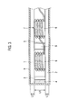
- Fig. 3 is a cross-sectional view of the optical fiber temperature sensor 1a according to example 1 of the present invention.
- the housings 1A to 1C included in the optical fiber temperature sensor 1a are each formed from an ultra-thin insulating sheet.
- an insulating material which can be molded into an ultra-thin sheet a glass epoxy resin laminated board is used for the housings.
- the housings 1A to 1C are each formed from a housing upper surface 1, a housing bottom surface 2 and housing side surfaces 3.
- An optical fiber cable 5 is housed inside each of the housings 1A to 1C.
- a silicone sealing 4 is applied to the housing side surfaces 3 using a silicone sealing material. All the surfaces of each housing is hermetically sealed with a hermetic sealing member 9 made from a silicone-based liquid insulating material. The hermetic quality can be enhanced using the hermetic sealing member 9.
- Multiple ultra-thin columnar members 6 made from the same material as the housing are housed in multiple locations inside each housing.
- Multiple sensor rings 7 are each formed by unfixedly winding a portion of the optical fiber cable 5 with a length equal to or longer than that corresponding to the range resolution around the corresponding one of the multiple ultra-thin columnar members 6. Because of the multiple sensor rings 7, the optical fiber cable 5 can detect temperatures in the respective locations without breaking even if shakes or excessive force is applied to the optical fiber cable 5.
- the provision of the multiple sensor rings 7 makes it possible to detect temperatures in desired locations in an area where the sensor rings 7 face the sandwich bus bars 10.
- circular spacers 8, each having the same configuration as and formed from the same material as the ultra-thin columnar members 6, are disposed so as to fill the spaces between the sensor rings 7. For this reason, even if excessive force is applied to the optical fiber temperature sensor and the optical fiber cable 5, neither the optical fiber temperature sensor nor the optical fiber cable 5 breaks, and the optical fiber cable 5 is capable of detecting the temperatures.
- the sandwich bus bars 10 be very close to each other; and the thickness of the optical fiber temperature sensor 1a be as thin as possible.
- the housing upper surface 1 and the housing bottom surface 2 are the ultra-thin sheets with thicknesses L2, L3 of 0.5 mm.
- the thickness L1 of the sensor rings 7 and the circular spacers 8 is set at 1 mm as a minimum dimension needed to wind the optical fiber cable 5. Accordingly, the entire thickness of the optical fiber temperature sensor 1a is set at 2 mm.
- the optical fiber cable 5 is wound around each ultra-thin columnar member 6 with a slight clearance in between.
- the optical fiber cable 5 shown in Fig. 1(B) is formed into the multiple sensor rings 7 by, starting from the lower end of the optical fiber temperature sensor 1a, being sequentially wound around the multiple ultra-thin columnar members 6 arranged in the right row in the optical fiber temperature sensor 1a. Furthermore, the optical fiber cable 5 is formed into the other multiple sensor rings 7 by, starting from the upper end of the optical fiber temperature sensor 1a, being sequentially wound around the multiple ultra-thin columnar members 6 arranged in the left row in the optical fiber temperature sensor 1a. The optical fiber cable 5 is hence brought back to the lower end of the optical fiber temperature sensor 1a.
- through-holes 11 are provided to the housing side surfaces 3 of the housings 1A to 1C.
- the housings 1A to 1C are integrated into one unit by connecting the housings together with the optical fiber cable 5 passing through the through-holes 11.
- Fig. 2 is a view showing another instance of the optical fiber temperature sensor of example 1 of the present invention.
- Fig. 2(A) is a perspective view showing structures of two sandwich bus bars 10a and a structure of an optical fiber temperature sensor 1b.
- Fig. 2 (B) is a perspective view showing the structure of the optical fiber temperature sensor 1b.
- the optical fiber temperature sensor 1b shown in Fig. 2 is disposed between phases of the two sandwich bus bars 10a in the board.
- a right-angle bent portion 10b is formed in each sandwich bus bar 10a, and the optical fiber temperature sensor 1b is produced in such a way that a right-angle bent portion 10B is formed parallel with the right-angle bent portion 10b.
- Through-holes 11 are provided to the right-angle bent portion 10B.
- the housings are integrated into one unit by connecting the housings together with the optical fiber cable 5 passing through the through-holes 11.
- the optical fiber temperature sensors 1a, 1b shown in Figs. 1 and 2 are each produced with a width wider than the sandwich bus bar 10 or 10a for the purpose of enhancing the quality of interphase insulation between the sandwich bus bars 10 or 10a.
- a temperature monitoring section formed from the sensor rings 7 and the circular spacers 8 is provided to only areas where the sandwich bus bars 10 or 10a overlap each other.
- the optical fiber temperature sensor according to example 1 is placed very close to the opposed sandwich bus bars 10 or 10a.
- the optical fiber temperature sensor is capable of constantly monitoring the temperatures respectively in the multiple desired locations, and makes it possible to prevent trouble.
- the optical fiber temperature sensor is capable of collecting a time-series change in the temperature from any position in each sensor ring 7.
- the aging and an abnormality of any of the sandwich bus bars 10, 10a can be monitored by observing their temperature change trends, such as sudden and rapid temperature changes as well as gradual and continuous temperature rises.
- the ultra-thin sheet structure enables the optical fiber temperature sensor to be installed in a narrow space, and this structure is excellent in achieving a lightweight property. Moreover, the optical fiber temperature sensor can be easily replaced, removed and attached for the maintenance purpose.
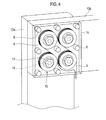
- Fig. 4 is a view showing a structure of an optical fiber temperature sensor according to example 2 of the present invention.
- a bus bar 12a (a first bus bar) and a bus bar 12b (a second bus bar) are bolt-fastened to each other using bolts 13.
- the feature of the optical fiber temperature sensor 1c in this case is to monitor the overheating of each bolt 13 in the bus bar connecting portion which is due to the concentration of current on the bolt 13 as a result of becoming loose.
- An optical fiber temperature sensor 1c is formed from an ultra-thin sheet, and is disposed on the bus bar 12b.
- the internal structure of the optical fiber temperature sensor 1c is the same as the structure shown in Fig. 3 .
- Fig. 4 multiple sensor rings 15 each having a bolt hole 14 are formed.
- the housing of the optical fiber temperature sensor 1c is formed from a glass-epoxy resin laminated board.
- the bolt holes 14 (the through-holes) matching the diameter of the bolts 13 are formed in the housing surface of the optical fiber temperature sensor 1c which is in contact with the bus bar 12b. Thereby, the optical fiber temperature sensor 1c is made to have a function as a glass-epoxy washer.
- the multiple ultra-shin circular members 6 are provided respectively with the bolt holes 14, matching the diameter of the bolts 13, and to which to attach the bolts. Passing through the bolt holes 14, the bolts 13 are bolt-fastened to the bus bar 12a and the bus bar 12b. Thereby, the optical fiber temperature sensor 1c is capable of monitoring the overheating of each bolt 13 in the bus bar connecting portion which is due to the concentration of current on the bolt 13 as a result of becoming loose.
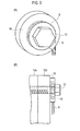
- Fig. 5 is a view showing a sheet-shaped structure of the optical fiber temperature sensor according to example 2 of the present invention, the sheet-shaped configuration matching a single bus bar connection portion.
- Fig. 5 (A) is a perspective view of the optical fiber temperature sensor.
- Fig. 5(B) is a cross-sectional view of the optical fiber temperature sensor.
- the optical fiber cable 5 is guided to a housing 16 from a measuring apparatus, which is not illustrated, and the sensor ring 15 is formed by winding the optical fiber cable 5 around the ultra-thin circular member 6 inside the housing 16 multiple times. Inserted through the sensor ring 15, the bolt 13 is bolt-fastened to the bus bar 12a and the bus bar 12b.
- the optical fiber temperature sensor functions as a glass-epoxy washer having a temperature sensing function as in the case of Fig. 4 , and can be formed into a desired shape.
- Fig. 6 is a configuration block diagram showing a temperature distribution measuring apparatus using the optical fiber temperature sensor according to the present invention. Referring to Fig. 6 , descriptions will be provided for the temperature distribution measuring apparatus using the optical fiber temperature sensor.
- the temperature distribution measuring apparatus includes a pulse generator 24, a light source 25, an optical spectroscope 26, an optical receiver 27, a data processor 28 and a data display unit 29.
- the pulse generator 24 generates a pulse signal, and outputs the pulse signal to the light source 25.
- the light source 25 outputs an optical signal to the optical spectroscope 26.
- the optical spectroscope 26 outputs the optical signal, coming from the light source 25, to as many optical fiber cables 30 as sensors for the sandwich bus bars 10 and the connecting bolts.
- the optical fiber temperature sensor according to example 1 and the optical fiber temperature sensor according to example 2 can be simultaneously installed in one measuring apparatus.
- the optical spectroscope 26 sends the optical signal to as many optical fiber cables 30 as the sensors, and outputs optical signals, sent from as many optical fiber cables 30 as the sensors, to the optical receiver 27.
- the data processor 28 measures the temperature distribution in a desired location from information on the temperatures of the optical fiber temperature sensors which the optical fiber cables 30 have.
- the data display unit 29 displays the temperature distribution in the desired location.
- the present invention is applicable to cubicle-type high-voltage power receiving and distributing facilities which are more likely to develop trouble due to severe environments such as typhoons, rainfalls and dust, or due to induced magnetic fields.
Landscapes
- Physics & Mathematics (AREA)
- General Physics & Mathematics (AREA)
- Measuring Temperature Or Quantity Of Heat (AREA)
Abstract
Description
- The present invention relates to an optical fiber temperature sensor configured to constantly monitor an abnormality in the temperature of components, such as bus bars and bolts constituting the inside of an electric appliance.
- With regard to inverter boards in recent years, as the frequency of switching operations becomes higher, a switching surge voltage becomes larger due to the inductance in the bus bars in the inverter boards. For this reason, it is important to reduce the switching surge voltage. Employment of so-called sandwich bus bars is effective for a reduction in the inductance. The sandwich bus bars include: a bus bar from which switching current flows into an end of a switching circuit for load control; and a bus bar to which the switching current flows out from the other end of the switching circuit. The two bus bars are set opposite each other with an electrically-insulating material interposed in between.
- However, inverter boards are likely to develop trouble, such as short-circuit, due to aging of the sandwich bus bars, and deterioration in insulation performance of the interphase insulating material between the sandwich bus bars. Conventional methods, however, cannot prevent such trouble.
- Furthermore, fastening bolts and the like for connecting the bus bars also become loose due to aging, vibration and shock. This leads to a problem of local overheating.
- A solution to problems like these is to perform monitoring to prevent sudden trouble inside an electrical appliance board such as an inverter board.
- Temperature monitoring apparatuses using optical fibers are used in a method of monitoring temperature abnormalities. Such temperature monitoring apparatuses are put into operation in various fields including tunnel disaster prevention facilities (see PTL 1, for example).
- According to PTL 1, one optical fiber cable installed in a tunnel along the lengthwise direction functions in its entire length as a temperature sensor, and collectively measures the temperature distribution in the entire length of the optical fiber cable from one end to the other. Thereby, it is detected whether a fire breaks out.
- Although the tunnel disaster prevention facility described in PTL 1 is capable of measuring the temperature distribution along the optical fiber cable in the lengthwise direction, the temperature measurement points are determined depending on the range resolution. For this reason, the tunnel disaster prevention facility are used for large-scale components, and large-scale linear structures typified by tunnels. Such optical fiber temperature monitoring apparatus, as it is, cannot be applied to very narrow spaces inside the appliances.
- The applications of optical fiber temperature monitoring apparatuses to narrow spaces are disclosed in
PTL 2 and PTL 3. - In an optical fiber temperature sensor described in
PTL 2, a portion of an optical fiber cable with a length equal to or longer than that corresponding to the range resolution is wound to measure a local temperature. According toPTL 2, the sensor unit is fixed together with an enhanced thermally-conductive filler using an adhesive, and is disposed in contact with a measurement object. - The temperature measurement precision of the optical fiber cable, however, decreases due to the fixing of the optical fiber cable and the enhanced thermally-conductive filler using the adhesive.
-
- [PTL 1] Japanese Patent Application Publication No.
Hei 8-4499 - [PTL 2] Japanese Patent Application Publication No.
Hei 7-181086 - [PTL 3] Japanese Patent Application PublicationNo.
2000-356473 - According to PTL 3, the object temperature of a crucible-type induction furnace is detected using optical fiber cables which are buried in a fire-resistant body for forming the crucible. PTL 3 is intended to detect only one temperature at the highest temperature location in an object having a certain capacity, and is not a case which needs specific measures for the temperature detection resolution of the optical fiber cable. In other words, PTL 3 is not suitable to detect multiple temperatures in the respective local positions in a narrow space.
- As described above, the conventional optical fiber temperature monitoring apparatuses can be easily applied to the operations of large-scale components and large-scale linear structures. However, no conventional optical fiber temperature monitoring apparatus has been yet applied to the operation in a limited space and narrow range like an inverter board. No conventional optical fiber temperature monitoring apparatus is capable of monitoring serious abnormalities, particularly the overheating of the bus bar.
- An object of the present invention is to provide an optical fiber temperature sensor capable of constantly monitoring temperatures respectively in multiple desired locations, and accordingly making it possible to prevent trouble, in the narrow range.
- To attain the object, an optical fiber temperature sensor according to the present invention provides an optical fiber temperature sensor, which implements a temperature monitoring function in an interphase insulating material between sandwich bus bars, and is characterized by the following features. Specifically, the optical fiber temperature sensor is formed by housing an optical fiber cable in a housing which is formed from an ultra-thin sheet made from an insulating material having insulation quality equal to or higher than the interphase insulating material between the sandwich bus bars. Multiple ultra-thin columnar members, each made from the same material as the housing, are housed in multiple locations in the housing. Multiple sensor rings are each formed by unfixedly winding a portion of the optical fiber cable with a length equal to or longer than that corresponding to range resolution around the corresponding one of the ultra-thin columnar members. The multiple sensor rings measure temperatures in the multiple locations, respectively. Silicone sealing is applied to housing side surfaces. All surfaces of the housing are hermetically sealed with a hermetic sealing member made from a silicone-based liquid insulating material.
-
- [
Fig. 1 ]
Fig. 1 is a view showing an instance of an optical fiber temperature sensor according to example 1 of the present invention. - [
Fig. 2 ]
Fig. 2 is a view of another instance of the optical fiber temperature sensor according to example 1 of the present invention. - [
Fig. 3 ]
Fig. 3 is a cross-sectional view of the optical fiber temperature sensor according to example 1 of the present invention. - [
Fig. 4 ]
Fig. 4 is a view showing a structure of an optical fiber temperature sensor according to example 2 of the present invention. - [
Fig. 5 ]
Fig. 5 is a view showing a sheet-shaped configuration of the optical fiber temperature sensor according to example 2 of the present invention, the sheet-shaped configuration matching a single bus bar connection portion. - [
Fig. 6 ]
Fig. 6 is a diagram showing a temperature distribution measuring apparatus using the optical fiber temperature sensor according to the present invention. - Referring to the drawings, descriptions will be hereinbelow provided for an optical fiber temperature sensor according to an embodiment of the present invention.
-
Fig. 1 is a view showing an instance of an optical fiber temperature sensor according to example 1 of the present invention.Fig. 1(A) is a perspective view showing the structures of twosandwich bus bars 10 and an opticalfiber temperature sensor 1a.Fig. 1 (B) is a perspective view showing the structure of the opticalfiber temperature sensor 1a. - The optical
fiber temperature sensor 1a shown inFig. 1 is disposed (in the interphase) between the two sandwich bus bars 10 in the board. In the example shown inFig. 1 , abent portion 10A is formed in eachsandwich bus bar 10, and the opticalfiber temperature sensor 1a is produced in a way that ahousing 1B is formed parallel with thebent portion 10A. - The optical
fiber temperature sensor 1a has ahousing 1A, thehousing 1B connected to thehousing 1A, and ahousing 1C connected to thehousing 1B in a location facing the two sandwich bus bars 10. -
Fig. 3 is a cross-sectional view of the opticalfiber temperature sensor 1a according to example 1 of the present invention. Thehousings 1A to 1C included in the opticalfiber temperature sensor 1a are each formed from an ultra-thin insulating sheet. As an insulating material which can be molded into an ultra-thin sheet, a glass epoxy resin laminated board is used for the housings. - The
housings 1A to 1C are each formed from a housing upper surface 1, ahousing bottom surface 2 and housing side surfaces 3. Anoptical fiber cable 5 is housed inside each of thehousings 1A to 1C. - A silicone sealing 4 is applied to the housing side surfaces 3 using a silicone sealing material. All the surfaces of each housing is hermetically sealed with a hermetic sealing member 9 made from a silicone-based liquid insulating material. The hermetic quality can be enhanced using the hermetic sealing member 9.
- Multiple ultra-thin
columnar members 6 made from the same material as the housing are housed in multiple locations inside each housing. Multiple sensor rings 7 are each formed by unfixedly winding a portion of theoptical fiber cable 5 with a length equal to or longer than that corresponding to the range resolution around the corresponding one of the multiple ultra-thincolumnar members 6. Because of the multiple sensor rings 7, theoptical fiber cable 5 can detect temperatures in the respective locations without breaking even if shakes or excessive force is applied to theoptical fiber cable 5. - Furthermore, the provision of the multiple sensor rings 7 makes it possible to detect temperatures in desired locations in an area where the sensor rings 7 face the sandwich bus bars 10.
- Moreover,
circular spacers 8, each having the same configuration as and formed from the same material as the ultra-thincolumnar members 6, are disposed so as to fill the spaces between the sensor rings 7. For this reason, even if excessive force is applied to the optical fiber temperature sensor and theoptical fiber cable 5, neither the optical fiber temperature sensor nor theoptical fiber cable 5 breaks, and theoptical fiber cable 5 is capable of detecting the temperatures. - For the purpose of reducing the wiring distance, it is desirable that: the sandwich bus bars 10 be very close to each other; and the thickness of the optical
fiber temperature sensor 1a be as thin as possible. To this end, the housing upper surface 1 and thehousing bottom surface 2 are the ultra-thin sheets with thicknesses L2, L3 of 0.5 mm. The thickness L1 of the sensor rings 7 and thecircular spacers 8 is set at 1 mm as a minimum dimension needed to wind theoptical fiber cable 5. Accordingly, the entire thickness of the opticalfiber temperature sensor 1a is set at 2 mm. Theoptical fiber cable 5 is wound around eachultra-thin columnar member 6 with a slight clearance in between. - The
optical fiber cable 5 shown inFig. 1(B) is formed into the multiple sensor rings 7 by, starting from the lower end of the opticalfiber temperature sensor 1a, being sequentially wound around the multiple ultra-thincolumnar members 6 arranged in the right row in the opticalfiber temperature sensor 1a. Furthermore, theoptical fiber cable 5 is formed into the other multiple sensor rings 7 by, starting from the upper end of the opticalfiber temperature sensor 1a, being sequentially wound around the multiple ultra-thincolumnar members 6 arranged in the left row in the opticalfiber temperature sensor 1a. Theoptical fiber cable 5 is hence brought back to the lower end of the opticalfiber temperature sensor 1a. - In this case, through-
holes 11 are provided to the housing side surfaces 3 of thehousings 1A to 1C. Thehousings 1A to 1C are integrated into one unit by connecting the housings together with theoptical fiber cable 5 passing through the through-holes 11. -
Fig. 2 is a view showing another instance of the optical fiber temperature sensor of example 1 of the present invention.Fig. 2(A) is a perspective view showing structures of twosandwich bus bars 10a and a structure of an opticalfiber temperature sensor 1b.Fig. 2 (B) is a perspective view showing the structure of the opticalfiber temperature sensor 1b. - The optical
fiber temperature sensor 1b shown inFig. 2 is disposed between phases of the twosandwich bus bars 10a in the board. In the example shown inFig. 2 , a right-anglebent portion 10b is formed in eachsandwich bus bar 10a, and the opticalfiber temperature sensor 1b is produced in such a way that a right-anglebent portion 10B is formed parallel with the right-anglebent portion 10b. Through-holes 11 are provided to the right-anglebent portion 10B. The housings are integrated into one unit by connecting the housings together with theoptical fiber cable 5 passing through the through-holes 11. - The optical
fiber temperature sensors Figs. 1 and2 are each produced with a width wider than thesandwich bus bar circular spacers 8 is provided to only areas where the sandwich bus bars 10 or 10a overlap each other. - As described above, the optical fiber temperature sensor according to example 1 is placed very close to the opposed sandwich bus bars 10 or 10a. For this reason, the optical fiber temperature sensor is capable of constantly monitoring the temperatures respectively in the multiple desired locations, and makes it possible to prevent trouble. In other words, the optical fiber temperature sensor is capable of collecting a time-series change in the temperature from any position in each
sensor ring 7. The aging and an abnormality of any of the sandwich bus bars 10, 10a can be monitored by observing their temperature change trends, such as sudden and rapid temperature changes as well as gradual and continuous temperature rises. - In addition, the ultra-thin sheet structure enables the optical fiber temperature sensor to be installed in a narrow space, and this structure is excellent in achieving a lightweight property. Moreover, the optical fiber temperature sensor can be easily replaced, removed and attached for the maintenance purpose.
-
Fig. 4 is a view showing a structure of an optical fiber temperature sensor according to example 2 of the present invention. - In
Fig. 4 , abus bar 12a (a first bus bar) and abus bar 12b (a second bus bar) are bolt-fastened to each other usingbolts 13. The feature of the opticalfiber temperature sensor 1c in this case is to monitor the overheating of eachbolt 13 in the bus bar connecting portion which is due to the concentration of current on thebolt 13 as a result of becoming loose. An opticalfiber temperature sensor 1c is formed from an ultra-thin sheet, and is disposed on thebus bar 12b. The internal structure of the opticalfiber temperature sensor 1c is the same as the structure shown inFig. 3 . - In
Fig. 4 , multiple sensor rings 15 each having abolt hole 14 are formed. Specifically, the housing of the opticalfiber temperature sensor 1c is formed from a glass-epoxy resin laminated board. The bolt holes 14 (the through-holes) matching the diameter of thebolts 13 are formed in the housing surface of the opticalfiber temperature sensor 1c which is in contact with thebus bar 12b. Thereby, the opticalfiber temperature sensor 1c is made to have a function as a glass-epoxy washer. - To put it concretely, the multiple ultra-shin
circular members 6 are provided respectively with the bolt holes 14, matching the diameter of thebolts 13, and to which to attach the bolts. Passing through the bolt holes 14, thebolts 13 are bolt-fastened to thebus bar 12a and thebus bar 12b. Thereby, the opticalfiber temperature sensor 1c is capable of monitoring the overheating of eachbolt 13 in the bus bar connecting portion which is due to the concentration of current on thebolt 13 as a result of becoming loose. -
Fig. 5 is a view showing a sheet-shaped structure of the optical fiber temperature sensor according to example 2 of the present invention, the sheet-shaped configuration matching a single bus bar connection portion.Fig. 5 (A) is a perspective view of the optical fiber temperature sensor.Fig. 5(B) is a cross-sectional view of the optical fiber temperature sensor. InFig. 5 , theoptical fiber cable 5 is guided to ahousing 16 from a measuring apparatus, which is not illustrated, and thesensor ring 15 is formed by winding theoptical fiber cable 5 around the ultra-thincircular member 6 inside thehousing 16 multiple times. Inserted through thesensor ring 15, thebolt 13 is bolt-fastened to thebus bar 12a and thebus bar 12b. Thereby, the optical fiber temperature sensor functions as a glass-epoxy washer having a temperature sensing function as in the case ofFig. 4 , and can be formed into a desired shape. -
Fig. 6 is a configuration block diagram showing a temperature distribution measuring apparatus using the optical fiber temperature sensor according to the present invention. Referring toFig. 6 , descriptions will be provided for the temperature distribution measuring apparatus using the optical fiber temperature sensor. The temperature distribution measuring apparatus includes apulse generator 24, alight source 25, anoptical spectroscope 26, anoptical receiver 27, adata processor 28 and adata display unit 29. - The
pulse generator 24 generates a pulse signal, and outputs the pulse signal to thelight source 25. In accordance with the pulse signal from thepulse generator 24, thelight source 25 outputs an optical signal to theoptical spectroscope 26. Theoptical spectroscope 26 outputs the optical signal, coming from thelight source 25, to as manyoptical fiber cables 30 as sensors for the sandwich bus bars 10 and the connecting bolts. The optical fiber temperature sensor according to example 1 and the optical fiber temperature sensor according to example 2 can be simultaneously installed in one measuring apparatus. - To this end, the
optical spectroscope 26 sends the optical signal to as manyoptical fiber cables 30 as the sensors, and outputs optical signals, sent from as manyoptical fiber cables 30 as the sensors, to theoptical receiver 27. On the basis of the optical signals from theoptical receiver 27, thedata processor 28 measures the temperature distribution in a desired location from information on the temperatures of the optical fiber temperature sensors which theoptical fiber cables 30 have. Thedata display unit 29 displays the temperature distribution in the desired location. - The present invention is applicable to cubicle-type high-voltage power receiving and distributing facilities which are more likely to develop trouble due to severe environments such as typhoons, rainfalls and dust, or due to induced magnetic fields.
Claims (3)
- An optical fiber temperature sensor which implements a temperature monitoring function in an interphase insulating material between sandwich bus bars, wherein
the optical fiber temperature sensor is formed by housing an optical fiber cable in a housing which is formed from an ultra-thin sheet made from an insulating material having insulation quality equal to or higher than the interphase insulating material between the sandwich bus bars,
a plurality of ultra-thin columnar members, each made from the same material as the housing, are housed in a plurality of locations in the housing,
a plurality of sensor rings are each formed by unfixedly winding a portion of the optical fiber cable with a length equal to or longer than that corresponding to range resolution around the corresponding one of the ultra-thin columnar members,
the plurality of sensor rings measure temperatures in the plurality of locations, respectively,
silicone sealing is applied to housing side surfaces, and all surfaces of the housing are hermetically sealed with a hermetic sealing member made from a silicone-based liquid insulating material. - The optical fiber temperature sensor according to claim 1, wherein a spacer, having the same configuration as the ultra-thin circular members, is disposed so as to fill a space between the sensor rings.
- An optical fiber temperature sensor configured to monitor temperatures of bolts connecting a first bus bar and a second bus bar together, wherein
the optical fiber temperature sensor is formed by housing an optical fiber cable in a housing which is formed from an ultra-thin sheet made from an insulating material,
a plurality of ultra-thin columnar members, each made from the same material as is the housing, are housed in a plurality of locations in the housing,
a plurality of sensor rings are each formed by unfixedly winding a portion of the optical fiber cable with a length equal to or longer than that corresponding to range resolution around the corresponding one of the ultra-thin columnar members,
the plurality of sensor rings measure temperatures in the plurality of locations, respectively,
silicone sealing is applied to housing side surfaces, all surfaces of the housing are hermetically sealed with a hermetic sealing member made from a silicone-based liquid insulating material, and
the multiple sensor rings have through-holes through which to install the bolts in the sensor rings, respectively.
Applications Claiming Priority (1)
| Application Number | Priority Date | Filing Date | Title |
|---|---|---|---|
| PCT/JP2012/064525 WO2013183126A1 (en) | 2012-06-06 | 2012-06-06 | Optical fiber thermal sensor |
Publications (3)
| Publication Number | Publication Date |
|---|---|
| EP2860502A1 true EP2860502A1 (en) | 2015-04-15 |
| EP2860502A4 EP2860502A4 (en) | 2016-02-24 |
| EP2860502B1 EP2860502B1 (en) | 2017-04-05 |
Family
ID=49711543
Family Applications (1)
| Application Number | Title | Priority Date | Filing Date |
|---|---|---|---|
| EP12878347.9A Active EP2860502B1 (en) | 2012-06-06 | 2012-06-06 | Optical fiber thermal sensor |
Country Status (6)
| Country | Link |
|---|---|
| US (1) | US9810588B2 (en) |
| EP (1) | EP2860502B1 (en) |
| JP (1) | JP5932996B2 (en) |
| KR (1) | KR101625327B1 (en) |
| CN (1) | CN104335019B (en) |
| WO (1) | WO2013183126A1 (en) |
Cited By (1)
| Publication number | Priority date | Publication date | Assignee | Title |
|---|---|---|---|---|
| US20190391176A1 (en) * | 2015-04-20 | 2019-12-26 | SZ DJI Technology Co., Ltd. | Systems and methods for thermally regulating sensor operation |
Families Citing this family (10)
| Publication number | Priority date | Publication date | Assignee | Title |
|---|---|---|---|---|
| GB2550531A (en) * | 2014-07-25 | 2017-11-29 | Sabmiller Plc | Packaging |
| US10741313B1 (en) * | 2019-02-06 | 2020-08-11 | Eaton Intelligent Power Limited | Bus bar assembly with integrated surge arrestor |
| CN110319951A (en) * | 2019-07-18 | 2019-10-11 | 华北电力科学研究院有限责任公司 | The temperature monitoring system and method for enclosed busbar |
| JP2021025997A (en) * | 2019-08-06 | 2021-02-22 | 王子ホールディングス株式会社 | Temperature measurement system for conveyor, method of laying optical fiber for temperature measurement on conveyor, and jig used therefor |
| CN114729841A (en) | 2019-12-05 | 2022-07-08 | Ls电气株式会社 | Optical fiber cable temperature measuring device |
| KR102372176B1 (en) * | 2020-05-26 | 2022-03-08 | 엘에스일렉트릭(주) | temperature measuring device using fiber optic cable |
| KR102326331B1 (en) * | 2019-12-05 | 2021-11-15 | 엘에스일렉트릭 (주) | panel type multi temperature measuring device |
| KR20230064897A (en) * | 2021-11-04 | 2023-05-11 | 엘에스일렉트릭(주) | Temperature measuring instrument |
| KR102913122B1 (en) | 2022-01-14 | 2026-01-14 | 엘에스일렉트릭(주) | Condition sensing module, guide member and power device include the same |
| EP4517284A1 (en) * | 2023-09-04 | 2025-03-05 | Prysmian S.p.A. | Cable termination anomaly detection method and system |
Family Cites Families (22)
| Publication number | Priority date | Publication date | Assignee | Title |
|---|---|---|---|---|
| US5991479A (en) * | 1984-05-14 | 1999-11-23 | Kleinerman; Marcos Y. | Distributed fiber optic sensors and systems |
| JPH084499B2 (en) | 1986-04-11 | 1996-01-24 | 積水化学工業株式会社 | Hydrolase activity promoter |
| WO1991000632A1 (en) * | 1989-06-29 | 1991-01-10 | National Research Development Corporation | Optical carrier generation using stimulated brillouin scattering |
| JP3029269B2 (en) | 1990-03-06 | 2000-04-04 | 株式会社東芝 | Insulation abnormality detector |
| US5035511A (en) * | 1990-04-10 | 1991-07-30 | The Babcock & Wilcox Company | Distributed fiber optic temperature sensor based on time domain transmission |
| JPH0420823A (en) | 1990-05-15 | 1992-01-24 | Kyowa Electron Instr Co Ltd | Measuring apparatus for exothermic temperature of axial part |
| US5028146A (en) * | 1990-05-21 | 1991-07-02 | Kabushiki Kaisha Toshiba | Apparatus and method for measuring temperatures by using optical fiber |
| JP2781269B2 (en) * | 1990-11-07 | 1998-07-30 | 株式会社ジャパンエナジー | Optical fiber sensor |
| JPH07151809A (en) | 1993-11-26 | 1995-06-16 | Fujitsu Syst Constr Kk | Detection of incompletely screwed part |
| JPH07181086A (en) * | 1993-12-22 | 1995-07-18 | Sumitomo Electric Ind Ltd | Optical fiber temperature sensor |
| JPH084499A (en) | 1994-06-20 | 1996-01-09 | Nohmi Bosai Ltd | Fire protection system in tunnel |
| JPH09130927A (en) | 1995-10-30 | 1997-05-16 | Toshiba Corp | Closed switchboard automatic inspection system |
| JP2000356473A (en) | 1999-06-16 | 2000-12-26 | Fuji Electric Co Ltd | Crucible induction furnace |
| JP2002081998A (en) * | 2000-09-05 | 2002-03-22 | Hitachi Cable Ltd | Temperature monitoring device for distribution board terminals |
| US20040179575A1 (en) * | 2003-01-23 | 2004-09-16 | Markham James R. | Instrument for temperature and condition monitoring of advanced turbine blades |
| JP2006177780A (en) | 2004-12-22 | 2006-07-06 | Hitachi Cable Ltd | Optical fiber temperature sensor, temperature sensor sheet and temperature measuring method |
| JP2006254623A (en) | 2005-03-11 | 2006-09-21 | Matsushita Electric Ind Co Ltd | Thermal monitoring device for electrical equipment |
| WO2007097490A1 (en) * | 2006-02-23 | 2007-08-30 | Ls Corp. | Bus duct with tube and bust duct system measurable the temperature |
| JP2010129406A (en) | 2008-11-28 | 2010-06-10 | Kitashiba Electric Co Ltd | Temperature monitoring system for induction heating device |
| CN102235884A (en) * | 2010-04-27 | 2011-11-09 | 西安金和光学科技有限公司 | Spiral optical fiber sensing device based on bending deformation of optical fiber |
| GB2490086B (en) * | 2010-11-08 | 2015-04-08 | Silixa Ltd | Fibre optic monitoring installation, apparatus and method |
| JP5657444B2 (en) * | 2011-03-23 | 2015-01-21 | 東京エレクトロン株式会社 | Temperature measuring apparatus and temperature measuring method |
-
2012
- 2012-06-06 JP JP2014519747A patent/JP5932996B2/en active Active
- 2012-06-06 EP EP12878347.9A patent/EP2860502B1/en active Active
- 2012-06-06 WO PCT/JP2012/064525 patent/WO2013183126A1/en not_active Ceased
- 2012-06-06 US US14/405,982 patent/US9810588B2/en active Active
- 2012-06-06 KR KR1020147036641A patent/KR101625327B1/en active Active
- 2012-06-06 CN CN201280073665.4A patent/CN104335019B/en active Active
Cited By (4)
| Publication number | Priority date | Publication date | Assignee | Title |
|---|---|---|---|---|
| US20190391176A1 (en) * | 2015-04-20 | 2019-12-26 | SZ DJI Technology Co., Ltd. | Systems and methods for thermally regulating sensor operation |
| US11703522B2 (en) * | 2015-04-20 | 2023-07-18 | SZ DJI Technology Co., Ltd. | Systems and methods for thermally regulating sensor operation |
| US20230358781A1 (en) * | 2015-04-20 | 2023-11-09 | SZ DJI Technology Co., Ltd. | Systems and methods for thermally regulating sensor operation |
| US12078653B2 (en) * | 2015-04-20 | 2024-09-03 | SZ DJI Technology Co., Ltd. | Systems and methods for thermally regulating sensor operation |
Also Published As
| Publication number | Publication date |
|---|---|
| US20150285692A1 (en) | 2015-10-08 |
| US9810588B2 (en) | 2017-11-07 |
| WO2013183126A1 (en) | 2013-12-12 |
| EP2860502B1 (en) | 2017-04-05 |
| CN104335019B (en) | 2016-11-16 |
| KR101625327B1 (en) | 2016-05-27 |
| EP2860502A4 (en) | 2016-02-24 |
| KR20150017366A (en) | 2015-02-16 |
| CN104335019A (en) | 2015-02-04 |
| JPWO2013183126A1 (en) | 2016-01-21 |
| JP5932996B2 (en) | 2016-06-08 |
Similar Documents
| Publication | Publication Date | Title |
|---|---|---|
| EP2860502B1 (en) | Optical fiber thermal sensor | |
| EP3283859B1 (en) | Enhanced optical condition monitoring system for power transformer and method for operating power transformer | |
| KR101529818B1 (en) | diagnosis system for monitoring status of switchboard | |
| CA2747378C (en) | Data collecting connection | |
| US10156602B2 (en) | Systems, methods, and devices for diagnosing integrity of electrical conductor-carrying systems | |
| KR102356233B1 (en) | busduct joint and multi point temperature monitering system of busduct including the same | |
| KR102124659B1 (en) | busduct joint | |
| WO2020220286A1 (en) | Power cable joint device and electric system | |
| KR101348013B1 (en) | Optical fiber temperature sensor | |
| CN119666074A (en) | Cable monitoring system and cable | |
| CN208488187U (en) | Fiber grating temperature sensor monitoring device for rail vehicle electric connecting point | |
| CN120089450B (en) | High-strength multi-cable-core control cable | |
| KR102945003B1 (en) | Bus-bar system for predicting fire | |
| KR102617922B1 (en) | Busway Temperature Monitoring System | |
| CN222704189U (en) | A hot spot detection and early warning system for oil field steam pipelines | |
| CN104901262A (en) | Insulating bush and switching cabinet | |
| JP2019045192A (en) | One-line ground fault current sensor and switch gear | |
| KR102741114B1 (en) | Real-time electric shock safety diagnosis system based on capacitance and relative leakage distribution analysis algorithm | |
| JPH0631701Y2 (en) | Winding temperature detector for stationary induction equipment | |
| JP3200298B2 (en) | Optical fiber type temperature distribution measuring device | |
| KR101897650B1 (en) | Bus duct and power supply system having the same | |
| CN204679182U (en) | Optical fiber distributed type power plant cable monitoring system | |
| ITMI20121139A1 (en) | MEASUREMENT DEVICE FOR STRING CURRENTS, IN PARTICULAR IN PHOTOVOLTAIC PLANTS |
Legal Events
| Date | Code | Title | Description |
|---|---|---|---|
| PUAI | Public reference made under article 153(3) epc to a published international application that has entered the european phase |
Free format text: ORIGINAL CODE: 0009012 |
|
| 17P | Request for examination filed |
Effective date: 20141209 |
|
| AK | Designated contracting states |
Kind code of ref document: A1 Designated state(s): AL AT BE BG CH CY CZ DE DK EE ES FI FR GB GR HR HU IE IS IT LI LT LU LV MC MK MT NL NO PL PT RO RS SE SI SK SM TR |
|
| AX | Request for extension of the european patent |
Extension state: BA ME |
|
| DAX | Request for extension of the european patent (deleted) | ||
| RA4 | Supplementary search report drawn up and despatched (corrected) |
Effective date: 20160121 |
|
| RIC1 | Information provided on ipc code assigned before grant |
Ipc: G01K 1/14 20060101ALI20160115BHEP Ipc: H02B 3/00 20060101ALI20160115BHEP Ipc: G01K 11/12 20060101AFI20160115BHEP |
|
| GRAP | Despatch of communication of intention to grant a patent |
Free format text: ORIGINAL CODE: EPIDOSNIGR1 |
|
| INTG | Intention to grant announced |
Effective date: 20161122 |
|
| GRAS | Grant fee paid |
Free format text: ORIGINAL CODE: EPIDOSNIGR3 |
|
| GRAA | (expected) grant |
Free format text: ORIGINAL CODE: 0009210 |
|
| AK | Designated contracting states |
Kind code of ref document: B1 Designated state(s): AL AT BE BG CH CY CZ DE DK EE ES FI FR GB GR HR HU IE IS IT LI LT LU LV MC MK MT NL NO PL PT RO RS SE SI SK SM TR |
|
| REG | Reference to a national code |
Ref country code: GB Ref legal event code: FG4D |
|
| REG | Reference to a national code |
Ref country code: CH Ref legal event code: EP |
|
| REG | Reference to a national code |
Ref country code: AT Ref legal event code: REF Ref document number: 882268 Country of ref document: AT Kind code of ref document: T Effective date: 20170415 |
|
| REG | Reference to a national code |
Ref country code: IE Ref legal event code: FG4D |
|
| REG | Reference to a national code |
Ref country code: DE Ref legal event code: R096 Ref document number: 602012030935 Country of ref document: DE |
|
| REG | Reference to a national code |
Ref country code: FR Ref legal event code: PLFP Year of fee payment: 6 |
|
| REG | Reference to a national code |
Ref country code: NL Ref legal event code: MP Effective date: 20170405 |
|
| REG | Reference to a national code |
Ref country code: LT Ref legal event code: MG4D |
|
| REG | Reference to a national code |
Ref country code: AT Ref legal event code: MK05 Ref document number: 882268 Country of ref document: AT Kind code of ref document: T Effective date: 20170405 |
|
| PG25 | Lapsed in a contracting state [announced via postgrant information from national office to epo] |
Ref country code: NL Free format text: LAPSE BECAUSE OF FAILURE TO SUBMIT A TRANSLATION OF THE DESCRIPTION OR TO PAY THE FEE WITHIN THE PRESCRIBED TIME-LIMIT Effective date: 20170405 |
|
| PG25 | Lapsed in a contracting state [announced via postgrant information from national office to epo] |
Ref country code: GR Free format text: LAPSE BECAUSE OF FAILURE TO SUBMIT A TRANSLATION OF THE DESCRIPTION OR TO PAY THE FEE WITHIN THE PRESCRIBED TIME-LIMIT Effective date: 20170706 Ref country code: HR Free format text: LAPSE BECAUSE OF FAILURE TO SUBMIT A TRANSLATION OF THE DESCRIPTION OR TO PAY THE FEE WITHIN THE PRESCRIBED TIME-LIMIT Effective date: 20170405 Ref country code: LT Free format text: LAPSE BECAUSE OF FAILURE TO SUBMIT A TRANSLATION OF THE DESCRIPTION OR TO PAY THE FEE WITHIN THE PRESCRIBED TIME-LIMIT Effective date: 20170405 Ref country code: NO Free format text: LAPSE BECAUSE OF FAILURE TO SUBMIT A TRANSLATION OF THE DESCRIPTION OR TO PAY THE FEE WITHIN THE PRESCRIBED TIME-LIMIT Effective date: 20170705 Ref country code: FI Free format text: LAPSE BECAUSE OF FAILURE TO SUBMIT A TRANSLATION OF THE DESCRIPTION OR TO PAY THE FEE WITHIN THE PRESCRIBED TIME-LIMIT Effective date: 20170405 Ref country code: AT Free format text: LAPSE BECAUSE OF FAILURE TO SUBMIT A TRANSLATION OF THE DESCRIPTION OR TO PAY THE FEE WITHIN THE PRESCRIBED TIME-LIMIT Effective date: 20170405 Ref country code: ES Free format text: LAPSE BECAUSE OF FAILURE TO SUBMIT A TRANSLATION OF THE DESCRIPTION OR TO PAY THE FEE WITHIN THE PRESCRIBED TIME-LIMIT Effective date: 20170405 |
|
| PG25 | Lapsed in a contracting state [announced via postgrant information from national office to epo] |
Ref country code: RS Free format text: LAPSE BECAUSE OF FAILURE TO SUBMIT A TRANSLATION OF THE DESCRIPTION OR TO PAY THE FEE WITHIN THE PRESCRIBED TIME-LIMIT Effective date: 20170405 Ref country code: BG Free format text: LAPSE BECAUSE OF FAILURE TO SUBMIT A TRANSLATION OF THE DESCRIPTION OR TO PAY THE FEE WITHIN THE PRESCRIBED TIME-LIMIT Effective date: 20170705 Ref country code: IS Free format text: LAPSE BECAUSE OF FAILURE TO SUBMIT A TRANSLATION OF THE DESCRIPTION OR TO PAY THE FEE WITHIN THE PRESCRIBED TIME-LIMIT Effective date: 20170805 Ref country code: PL Free format text: LAPSE BECAUSE OF FAILURE TO SUBMIT A TRANSLATION OF THE DESCRIPTION OR TO PAY THE FEE WITHIN THE PRESCRIBED TIME-LIMIT Effective date: 20170405 Ref country code: LV Free format text: LAPSE BECAUSE OF FAILURE TO SUBMIT A TRANSLATION OF THE DESCRIPTION OR TO PAY THE FEE WITHIN THE PRESCRIBED TIME-LIMIT Effective date: 20170405 Ref country code: SE Free format text: LAPSE BECAUSE OF FAILURE TO SUBMIT A TRANSLATION OF THE DESCRIPTION OR TO PAY THE FEE WITHIN THE PRESCRIBED TIME-LIMIT Effective date: 20170405 |
|
| REG | Reference to a national code |
Ref country code: DE Ref legal event code: R097 Ref document number: 602012030935 Country of ref document: DE |
|
| PG25 | Lapsed in a contracting state [announced via postgrant information from national office to epo] |
Ref country code: SK Free format text: LAPSE BECAUSE OF FAILURE TO SUBMIT A TRANSLATION OF THE DESCRIPTION OR TO PAY THE FEE WITHIN THE PRESCRIBED TIME-LIMIT Effective date: 20170405 Ref country code: RO Free format text: LAPSE BECAUSE OF FAILURE TO SUBMIT A TRANSLATION OF THE DESCRIPTION OR TO PAY THE FEE WITHIN THE PRESCRIBED TIME-LIMIT Effective date: 20170405 Ref country code: MC Free format text: LAPSE BECAUSE OF FAILURE TO SUBMIT A TRANSLATION OF THE DESCRIPTION OR TO PAY THE FEE WITHIN THE PRESCRIBED TIME-LIMIT Effective date: 20170405 Ref country code: CZ Free format text: LAPSE BECAUSE OF FAILURE TO SUBMIT A TRANSLATION OF THE DESCRIPTION OR TO PAY THE FEE WITHIN THE PRESCRIBED TIME-LIMIT Effective date: 20170405 Ref country code: EE Free format text: LAPSE BECAUSE OF FAILURE TO SUBMIT A TRANSLATION OF THE DESCRIPTION OR TO PAY THE FEE WITHIN THE PRESCRIBED TIME-LIMIT Effective date: 20170405 Ref country code: DK Free format text: LAPSE BECAUSE OF FAILURE TO SUBMIT A TRANSLATION OF THE DESCRIPTION OR TO PAY THE FEE WITHIN THE PRESCRIBED TIME-LIMIT Effective date: 20170405 |
|
| REG | Reference to a national code |
Ref country code: CH Ref legal event code: PL |
|
| PLBE | No opposition filed within time limit |
Free format text: ORIGINAL CODE: 0009261 |
|
| STAA | Information on the status of an ep patent application or granted ep patent |
Free format text: STATUS: NO OPPOSITION FILED WITHIN TIME LIMIT |
|
| PG25 | Lapsed in a contracting state [announced via postgrant information from national office to epo] |
Ref country code: SM Free format text: LAPSE BECAUSE OF FAILURE TO SUBMIT A TRANSLATION OF THE DESCRIPTION OR TO PAY THE FEE WITHIN THE PRESCRIBED TIME-LIMIT Effective date: 20170405 |
|
| 26N | No opposition filed |
Effective date: 20180108 |
|
| REG | Reference to a national code |
Ref country code: IE Ref legal event code: MM4A |
|
| GBPC | Gb: european patent ceased through non-payment of renewal fee |
Effective date: 20170705 |
|
| PG25 | Lapsed in a contracting state [announced via postgrant information from national office to epo] |
Ref country code: LU Free format text: LAPSE BECAUSE OF NON-PAYMENT OF DUE FEES Effective date: 20170606 Ref country code: LI Free format text: LAPSE BECAUSE OF NON-PAYMENT OF DUE FEES Effective date: 20170630 Ref country code: GB Free format text: LAPSE BECAUSE OF NON-PAYMENT OF DUE FEES Effective date: 20170705 Ref country code: CH Free format text: LAPSE BECAUSE OF NON-PAYMENT OF DUE FEES Effective date: 20170630 Ref country code: IE Free format text: LAPSE BECAUSE OF NON-PAYMENT OF DUE FEES Effective date: 20170606 |
|
| REG | Reference to a national code |
Ref country code: FR Ref legal event code: PLFP Year of fee payment: 7 |
|
| PG25 | Lapsed in a contracting state [announced via postgrant information from national office to epo] |
Ref country code: SI Free format text: LAPSE BECAUSE OF FAILURE TO SUBMIT A TRANSLATION OF THE DESCRIPTION OR TO PAY THE FEE WITHIN THE PRESCRIBED TIME-LIMIT Effective date: 20170405 |
|
| REG | Reference to a national code |
Ref country code: BE Ref legal event code: MM Effective date: 20170630 |
|
| PG25 | Lapsed in a contracting state [announced via postgrant information from national office to epo] |
Ref country code: BE Free format text: LAPSE BECAUSE OF NON-PAYMENT OF DUE FEES Effective date: 20170630 |
|
| PG25 | Lapsed in a contracting state [announced via postgrant information from national office to epo] |
Ref country code: MT Free format text: LAPSE BECAUSE OF NON-PAYMENT OF DUE FEES Effective date: 20170606 |
|
| PG25 | Lapsed in a contracting state [announced via postgrant information from national office to epo] |
Ref country code: HU Free format text: LAPSE BECAUSE OF FAILURE TO SUBMIT A TRANSLATION OF THE DESCRIPTION OR TO PAY THE FEE WITHIN THE PRESCRIBED TIME-LIMIT; INVALID AB INITIO Effective date: 20120606 |
|
| PG25 | Lapsed in a contracting state [announced via postgrant information from national office to epo] |
Ref country code: CY Free format text: LAPSE BECAUSE OF FAILURE TO SUBMIT A TRANSLATION OF THE DESCRIPTION OR TO PAY THE FEE WITHIN THE PRESCRIBED TIME-LIMIT Effective date: 20170405 |
|
| PG25 | Lapsed in a contracting state [announced via postgrant information from national office to epo] |
Ref country code: MK Free format text: LAPSE BECAUSE OF FAILURE TO SUBMIT A TRANSLATION OF THE DESCRIPTION OR TO PAY THE FEE WITHIN THE PRESCRIBED TIME-LIMIT Effective date: 20170405 |
|
| PG25 | Lapsed in a contracting state [announced via postgrant information from national office to epo] |
Ref country code: TR Free format text: LAPSE BECAUSE OF FAILURE TO SUBMIT A TRANSLATION OF THE DESCRIPTION OR TO PAY THE FEE WITHIN THE PRESCRIBED TIME-LIMIT Effective date: 20170405 |
|
| PG25 | Lapsed in a contracting state [announced via postgrant information from national office to epo] |
Ref country code: PT Free format text: LAPSE BECAUSE OF FAILURE TO SUBMIT A TRANSLATION OF THE DESCRIPTION OR TO PAY THE FEE WITHIN THE PRESCRIBED TIME-LIMIT Effective date: 20170405 |
|
| PG25 | Lapsed in a contracting state [announced via postgrant information from national office to epo] |
Ref country code: AL Free format text: LAPSE BECAUSE OF FAILURE TO SUBMIT A TRANSLATION OF THE DESCRIPTION OR TO PAY THE FEE WITHIN THE PRESCRIBED TIME-LIMIT Effective date: 20170405 |
|
| PGFP | Annual fee paid to national office [announced via postgrant information from national office to epo] |
Ref country code: DE Payment date: 20250429 Year of fee payment: 14 |
|
| PGFP | Annual fee paid to national office [announced via postgrant information from national office to epo] |
Ref country code: IT Payment date: 20250522 Year of fee payment: 14 |
|
| PGFP | Annual fee paid to national office [announced via postgrant information from national office to epo] |
Ref country code: FR Payment date: 20250508 Year of fee payment: 14 |