EP2860369B1 - System and device for reducing reductant deposit formation in exhaust aftertreatment systems - Google Patents
System and device for reducing reductant deposit formation in exhaust aftertreatment systems Download PDFInfo
- Publication number
- EP2860369B1 EP2860369B1 EP14187835.5A EP14187835A EP2860369B1 EP 2860369 B1 EP2860369 B1 EP 2860369B1 EP 14187835 A EP14187835 A EP 14187835A EP 2860369 B1 EP2860369 B1 EP 2860369B1
- Authority
- EP
- European Patent Office
- Prior art keywords
- exhaust flow
- reductant
- directing device
- exhaust
- decomposition chamber
- Prior art date
- Legal status (The legal status is an assumption and is not a legal conclusion. Google has not performed a legal analysis and makes no representation as to the accuracy of the status listed.)
- Active
Links
Images


Classifications
-
- F—MECHANICAL ENGINEERING; LIGHTING; HEATING; WEAPONS; BLASTING
- F01—MACHINES OR ENGINES IN GENERAL; ENGINE PLANTS IN GENERAL; STEAM ENGINES
- F01N—GAS-FLOW SILENCERS OR EXHAUST APPARATUS FOR MACHINES OR ENGINES IN GENERAL; GAS-FLOW SILENCERS OR EXHAUST APPARATUS FOR INTERNAL-COMBUSTION ENGINES
- F01N3/00—Exhaust or silencing apparatus having means for purifying, rendering innocuous, or otherwise treating exhaust
- F01N3/08—Exhaust or silencing apparatus having means for purifying, rendering innocuous, or otherwise treating exhaust for rendering innocuous
- F01N3/10—Exhaust or silencing apparatus having means for purifying, rendering innocuous, or otherwise treating exhaust for rendering innocuous by thermal or catalytic conversion of noxious components of exhaust
- F01N3/24—Exhaust or silencing apparatus having means for purifying, rendering innocuous, or otherwise treating exhaust for rendering innocuous by thermal or catalytic conversion of noxious components of exhaust characterised by constructional aspects of converting apparatus
- F01N3/28—Construction of catalytic reactors
- F01N3/2892—Exhaust flow directors or the like, e.g. upstream of catalytic device
-
- F—MECHANICAL ENGINEERING; LIGHTING; HEATING; WEAPONS; BLASTING
- F01—MACHINES OR ENGINES IN GENERAL; ENGINE PLANTS IN GENERAL; STEAM ENGINES
- F01N—GAS-FLOW SILENCERS OR EXHAUST APPARATUS FOR MACHINES OR ENGINES IN GENERAL; GAS-FLOW SILENCERS OR EXHAUST APPARATUS FOR INTERNAL-COMBUSTION ENGINES
- F01N3/00—Exhaust or silencing apparatus having means for purifying, rendering innocuous, or otherwise treating exhaust
- F01N3/08—Exhaust or silencing apparatus having means for purifying, rendering innocuous, or otherwise treating exhaust for rendering innocuous
- F01N3/10—Exhaust or silencing apparatus having means for purifying, rendering innocuous, or otherwise treating exhaust for rendering innocuous by thermal or catalytic conversion of noxious components of exhaust
- F01N3/18—Exhaust or silencing apparatus having means for purifying, rendering innocuous, or otherwise treating exhaust for rendering innocuous by thermal or catalytic conversion of noxious components of exhaust characterised by methods of operation; Control
- F01N3/20—Exhaust or silencing apparatus having means for purifying, rendering innocuous, or otherwise treating exhaust for rendering innocuous by thermal or catalytic conversion of noxious components of exhaust characterised by methods of operation; Control specially adapted for catalytic conversion
- F01N3/206—Adding periodically or continuously substances to exhaust gases for promoting purification, e.g. catalytic material in liquid form, NOx reducing agents
- F01N3/2066—Selective catalytic reduction [SCR]
-
- F—MECHANICAL ENGINEERING; LIGHTING; HEATING; WEAPONS; BLASTING
- F01—MACHINES OR ENGINES IN GENERAL; ENGINE PLANTS IN GENERAL; STEAM ENGINES
- F01N—GAS-FLOW SILENCERS OR EXHAUST APPARATUS FOR MACHINES OR ENGINES IN GENERAL; GAS-FLOW SILENCERS OR EXHAUST APPARATUS FOR INTERNAL-COMBUSTION ENGINES
- F01N2240/00—Combination or association of two or more different exhaust treating devices, or of at least one such device with an auxiliary device, not covered by indexing codes F01N2230/00 or F01N2250/00, one of the devices being
- F01N2240/20—Combination or association of two or more different exhaust treating devices, or of at least one such device with an auxiliary device, not covered by indexing codes F01N2230/00 or F01N2250/00, one of the devices being a flow director or deflector
-
- F—MECHANICAL ENGINEERING; LIGHTING; HEATING; WEAPONS; BLASTING
- F01—MACHINES OR ENGINES IN GENERAL; ENGINE PLANTS IN GENERAL; STEAM ENGINES
- F01N—GAS-FLOW SILENCERS OR EXHAUST APPARATUS FOR MACHINES OR ENGINES IN GENERAL; GAS-FLOW SILENCERS OR EXHAUST APPARATUS FOR INTERNAL-COMBUSTION ENGINES
- F01N2610/00—Adding substances to exhaust gases
- F01N2610/02—Adding substances to exhaust gases the substance being ammonia or urea
-
- F—MECHANICAL ENGINEERING; LIGHTING; HEATING; WEAPONS; BLASTING
- F01—MACHINES OR ENGINES IN GENERAL; ENGINE PLANTS IN GENERAL; STEAM ENGINES
- F01N—GAS-FLOW SILENCERS OR EXHAUST APPARATUS FOR MACHINES OR ENGINES IN GENERAL; GAS-FLOW SILENCERS OR EXHAUST APPARATUS FOR INTERNAL-COMBUSTION ENGINES
- F01N2610/00—Adding substances to exhaust gases
- F01N2610/14—Arrangements for the supply of substances, e.g. conduits
- F01N2610/1453—Sprayers or atomisers; Arrangement thereof in the exhaust apparatus
-
- Y—GENERAL TAGGING OF NEW TECHNOLOGICAL DEVELOPMENTS; GENERAL TAGGING OF CROSS-SECTIONAL TECHNOLOGIES SPANNING OVER SEVERAL SECTIONS OF THE IPC; TECHNICAL SUBJECTS COVERED BY FORMER USPC CROSS-REFERENCE ART COLLECTIONS [XRACs] AND DIGESTS
- Y02—TECHNOLOGIES OR APPLICATIONS FOR MITIGATION OR ADAPTATION AGAINST CLIMATE CHANGE
- Y02T—CLIMATE CHANGE MITIGATION TECHNOLOGIES RELATED TO TRANSPORTATION
- Y02T10/00—Road transport of goods or passengers
- Y02T10/10—Internal combustion engine [ICE] based vehicles
- Y02T10/12—Improving ICE efficiencies
Definitions
- the present application generally relates to internal combustion systems, and more particularly, to exhaust aftertreatment systems for diesel engines.
- US2010005791 discloses an apparatus and method for control of fluid flow through a conduit of an exhaust system for an engine, particularly prior to an exhaust treatment device.
- a fluid flow control device for receiving and guiding exhaust gas from an engine towards an exhaust gas treatment device.
- the fluid flow control device includes a nozzle disposed within an exhaust conduit of the engine.
- the nozzle includes an inlet opening and an outlet opening for forming a first flow path through the nozzle.
- the nozzle is spaced from the exhaust conduit for forming a second flow path between the nozzle and the exhaust conduit.
- the fluid flow control device also includes an injector disposed adjacent the nozzle. The injector may be oriented to direct a pressurized fluid to the first or second flow path.
- the present disclosure relates to a unique system and device to reduce reductant deposit formation in the exhaust system that directs at least a portion of an exhaust flow toward a reductant opening in an exhaust aftertreatment system.
- System 100 that includes an exhaust aftertreatment system 110.
- System 100 may be provided on any suitable application, such as a vehicle powered by an engine 102 such as a diesel engine, or on an engine 102 utilized in other applications such as power generation, pumping, marine, and locomotive systems.
- Engine 102 includes an intake system 104 through which charge air enters and an exhaust system 106 through which a flow of exhaust gas resulting from combustion exits, it being understood that not all details of these systems that are typically present are shown.
- Engine 102 includes a number of cylinders forming combustion chambers in which fuel combusts with the charge air that has entered through intake system 104.
- the combustion process produces a significant amount of emissions, most prominent being nitric oxide (NO) and nitrogen dioxide (NO 2 ), commonly known as NO x .
- NO x nitrogen dioxide
- Other emissions include particulates, carbon monoxide (CO), and hydrocarbons (HC).
- the exhaust gas is treated by one or more aftertreatment devices in the exhaust aftertreatment system 110 to reduce or eliminate such emissions.
- the exhaust system 106 includes the exhaust aftertreatment system 110 having one or more selective catalytic reduction (SCR) catalysts 116, and one or more locations for receiving a reductant from a reductant dosing system 120.
- a reductant injector 114 is mounted on a portion of exhaust system 106 upstream of SCR catalyst 116 with its outlet, or nozzle, arranged to spray reductant into the exhaust system 106 where it mixes with engine exhaust gas produced by engine 102.
- SCR catalyst 116 promotes a chemical reaction between the reductant and NOx in the exhaust gas that converts substantial amounts of NOx to reduce NOx emissions before the exhaust gas passes into the atmosphere.
- the exhaust aftertreatment system further includes an exhaust flow directing device 112 in the exhaust flow path upstream of the reductant injector 114.
- Exhaust flow directing device 112 directs at least a portion of the exhaust flow toward the reductant injector 114 to efficiently mix the exhaust gas and the reductant sprayed into the exhaust system 106 by the reductant injector 114.
- the efficient mixing of the exhaust gas and the reductant reduces reductant deposit formation in exhaust system 106. Reducing the reductant deposit formation increases the exhaust aftertreatment system's reliability and ability to meet emission requirements.
- the exhaust flow directing device 112 is further detailed below.
- the aftertreatment system 110 may include one or more other aftertreatment components not shown, such as diesel oxidation catalysts, diesel particulate filters, an ammonia oxidation catalyst, and various temperature, pressure and exhaust gas constituent sensors.
- Exhaust system 106 may also include various components not shown, such an exhaust gas recirculation system, a turbocharger system, coolers, and other components connecting exhaust system 106 to intake system 104.
- Reductant dosing system 120 receives reductant from a reductant storage tank (not shown) and provides the reductant to the exhaust system 106 via injector 114 or any suitable device or arrangement for injection or delivery of reductant to a decomposition chamber or directly to the exhaust system 106.
- an injector includes any nozzle, static device, electronically controllable device, and/or mechanical actuator that provides an outlet for reductant delivery into the exhaust flow path.
- a suitable reductant is a diesel exhaust fluid (DEF) which comprises a solution of 32.5% high purity urea and 67.5% deionized water. It shall be appreciated, however, that any suitable reductant for injection into an exhaust system with dosing system 120 may also be utilized.
- DEF diesel exhaust fluid
- Fig. 2 illustrates an exemplary embodiment of an exhaust aftertreatment apparatus 200.
- the aftertreatment apparatus 200 includes a housing 204 that defines a decomposition chamber 210 and a substrate chamber 230.
- decomposition chamber 210 and substrate chamber 230 are defined by separate housings.
- the separate housings can be connected directly to one another or connected to one another by a conduit.
- the decomposition chamber 210 includes an inlet 212 for receiving an exhaust stream 202 produced from operation of the engine 102.
- An exhaust flow directing device 214 is located in or adjacent inlet 212 in the exhaust stream 202 flow path. Exhaust flow directing device 214 can be secured to inlet 212 by one or more braces 216.
- exhaust flow directing device 214 is mounted to a wall of housing 204, an exhaust conduit connected to inlet 212, or other structure of the exhaust system.
- the decomposition chamber 210 is coupled to the reductant system 120 by at least one reductant injector opening 222 of the reductant injector 114 that is configured to inject a reductant into the exhaust stream 202 through the reductant injector opening 222.
- the substrate chamber 230 is connected to decomposition chamber 210 through a substrate chamber inlet 232 for receiving the mixed reductant and exhaust stream 202 from decomposition chamber 210 into the substrate chamber.
- Inlet 232 is offset axially from the inlet 212 so that the exhaust stream 202 travels from a first side of decomposition chamber 210 where reductant opening 222 is located to an opposite side of decomposition chamber 210 for delivery of the mixed reductant and exhaust stream to substrate chamber 230.
- the offset arrangement provides a compact flow path that promotes mixing of the reductant and exhaust gas before delivery to substrate chamber 230.
- the substrate chamber 230 further includes one or more SCR catalysts 234 for promoting a chemical reaction between the reductant and NOx in the exhaust stream 202.
- the exhaust flow directing device 214 is mounted in the decomposition chamber inlet 212 to create a space between an outer surface of the exhaust flow directing device 214 and an inner surface of the decomposition chamber inlet 212.
- the space defines a first flow path 240 where at least a portion of the exhaust stream is directed through the space.
- a second flow path 242 is defined through the interior of the exhaust flow directing device 214. The second flow path 242 directs a second portion of the exhaust stream toward the reductant injector opening 222, creating a shear force across the reductant opening 222 which reduces the formation of reductant deposits.
- first and second flow paths 240, 242 separate the exhaust flow in a manner that reduces exhaust gas recirculation in the decomposition chamber 210, further reducing the formation of reductant deposits, without decreasing the flow of the exhaust stream 202 to the SCR catalysts 234.
- the exhaust aftertreatment apparatus 200 illustrated in Fig. 2 shows the exhaust stream 202 entering a decomposition chamber inlet 212 that is located on the end of the decomposition chamber 210.
- the exhaust flow directing device 214 can be configured to accommodate alternative means of exhaust stream 202 entry into the decomposition chamber 210, depending on where the decomposition chamber inlet 212 is positioned relative to the housing 204 and the outlet 236.
- inlet 212 can be located on the side of housing 204.
- an end inlet and end outlet such as shown in Fig. 2 , are oriented in the same direction relative to the exhaust flow through housing 204, while a side inlet and end outlet are located in transverse orientations relative to one another on housing 204.
- exhaust flow directing device 314 in Figs. 4A-4B is an example embodiment used in a side inlet, end outlet type exhaust flow directing device, although exhaust flow directing device 214 could be used in a side inlet arrangement and exhaust flow directing device 314 of Figs. 4A-4B could be used in an end inlet arrangement.
- Exhaust flow directing device 214 includes a body 250 that has a conical frustum shape extending between a first end 260 and an opposite second end 262. Second end 262 is located toward decomposition chamber 230 and first end 260 is located away from second end 262 to receive the exhaust flow.
- Body 250 includes an inner surface 252 defining the second flow path 242 and an opposite outer surface 254 that, with the inner surface of inlet 212, defines first flow path 240.
- Body 250 further defines an opening or slot 258 along one side thereof that is oriented toward reductant opening 222 to direct at least a portion of exhaust flow toward reductant opening 222.
- Slot 258 provides an opening through which first flow path 240 and second flow path 242 communicate with one another.
- Braces 216 are connected to outer surface 254 and project radially outwardly therefrom for mounting with, for example, inlet 212 to space outer wall surface 254 from the inner surface of inlet 212 and form and maintain the opening of first flow channel 240.
- exhaust flow directing device 314 is shown that is similar to exhaust flow targeting device 214.
- Exhaust flow targeting device includes first and second wall segments 350a, 350b with facing ends that form opposite slots 358a, 358b.
- Braces 216 are secured to respective ones of the wall segments 350a, 350b for mounting of exhaust flow directing device 314 in inlet 212 in a manner similar to that discussed above with respect to exhaust flow directing device 214, such as shown in Fig. 4B .
- Opposite slots 358a, 358b provide fluid communication between first flow path 240 and second flow path 242 at opposite sides of exhaust flow directing device 314.
- one aspect involves a system that includes an internal combustion engine operable to produce an exhaust stream and an aftertreatment exhaust component assembly connected to the engine to receive the exhaust, the aftertreatment exhaust component assembly includes a decomposition chamber connected to a reduction assembly, the reduction assembly includes a catalyst downstream of the decomposition chamber, the decomposition chamber includes an inlet upstream of the connection with the reductant assembly and further includes an exhaust flow targeting device at the inlet, and the exhaust flow targeting device is configured to define a first exhaust flow path through the exhaust flow targeting device at the reductant system connection, and further configured to define a second exhaust flow path between an outer wall of the exhaust flow targeting device and the inlet.
- the exhaust flow directing device is configured to direct exhaust flow toward the connection with reductant source.
- the exhaust flow directing device includes a frusto-conically shaped body that expands outwardly in a direction of the exhaust flow.
- the body includes at least one slot forming a side opening of the body oriented toward the reductant opening.
- the body includes a second slot forming a second side opening opposite the side opening.
- the body is formed by first and second wall segments that extend between the side openings.
- the reductant system comprises a reductant storage tank, a reductant injector connected to the storage tank via a pump, and a doser tip connected to the reductant injector configured to be in the exhaust stream downstream of the exhaust flow targeting device.
- an exhaust emission aftertreatment apparatus that includes at least one housing defining a decomposition chamber fluidly coupled with a substrate chamber, wherein the substrate chamber houses a catalyst and the decomposition chamber is positioned upstream of the substrate chamber, the housing including an inlet into the decomposition chamber and a reductant opening downstream of the inlet for providing a flow of reductant into the decomposition chamber; and an exhaust flow directing device positioned at least partially in the inlet, wherein the exhaust flow directing device is configured relative to the inlet to direct a first portion of the exhaust flow along a first flow path that extends through the exhaust flow directing device into the decomposition chamber and a second portion of the exhaust flow along a second flow path that extends around the exhaust flow directing device into the decomposition chamber.
- the exhaust flow directing device is connected to and spaced inwardly from an inner surface of the inlet by a plurality of braces to define the second flow path.
- the exhaust flow directing device defines an outwardly tapered configuration for the first flow path in a direction of exhaust flow into the decomposition chamber.
- the exhaust flow directing device defines a first slot oriented toward the reductant opening and the slot extends between the first flow path and the second flow path.
- the exhaust flow directing device defines a second slot opposite the first slot, wherein each of the first and second slots extends between the first and second flow paths.
- the exhaust flow directing device defines a conical frustum shape that is oriented to expand in a direction of the exhaust flow into the decomposition chamber.
- the exhaust flow directing device includes an inner end oriented toward the decomposition chamber and an oppositely facing outer end, and a slot that extends through a wall of the exhaust flow directing device from the inner end to the outer end, wherein the slot is oriented toward the opening for the reductant.
- the exhaust flow directing device includes a first wall segment and a second wall segment, wherein a first end of each of the first and second walls segments are separated by the slot and an opposite second end of the first and second wall segments are separated by a second slot.
- the exhaust flow directing device is configured to direct exhaust flow toward the reductant opening.
- the decomposition chamber and the substrate chamber are defined by a common housing or by separate housings.
- the apparatus in another embodiment, includes at least one housing defining a decomposition chamber fluidly coupled with a substrate chamber, wherein the substrate chamber houses a catalyst and the decomposition chamber is positioned upstream of the substrate chamber, the housing including an inlet into the decomposition chamber and a reductant opening downstream of the inlet for providing a flow of reductant into the decomposition chamber; and an exhaust flow directing device positioned at least partially in the inlet, wherein the exhaust flow directing device includes a frusto-conically shaped body that expands in a direction of the exhaust flow and the body includes at least one slot forming a side opening of the body oriented toward the reductant opening.
- the body includes a second slot forming a second side opening opposite the side opening.
- the body is formed by first and second wall segments that extend between the side openings.
Landscapes
- Chemical & Material Sciences (AREA)
- Engineering & Computer Science (AREA)
- Chemical Kinetics & Catalysis (AREA)
- Health & Medical Sciences (AREA)
- Toxicology (AREA)
- Combustion & Propulsion (AREA)
- Mechanical Engineering (AREA)
- General Engineering & Computer Science (AREA)
- Exhaust Gas After Treatment (AREA)
Description
- The present application generally relates to internal combustion systems, and more particularly, to exhaust aftertreatment systems for diesel engines.
- Modem systems that include internal combustion engines often include a selective catalytic reduction (SCR) exhaust aftertreatment system to control exhaust system emissions. SCR systems typically include a reductant storage tank connected to a pump and a doser that injects reductant into the exhaust stream that, in conjunction with an SCR catalyst, operates to reduce NOx emissions. Even under normal operating conditions, reductant injected into the exhaust stream causes reductant buildup over time and, more specifically, reductant deposit formation near where the reductant is injected into the exhaust stream. Therefore, a need remains for further improvements in exhaust aftertreatment systems to reduce the formation of reductant deposits.
-
US2010005791 discloses an apparatus and method for control of fluid flow through a conduit of an exhaust system for an engine, particularly prior to an exhaust treatment device. In one embodiment, a fluid flow control device for receiving and guiding exhaust gas from an engine towards an exhaust gas treatment device is provided. The fluid flow control device includes a nozzle disposed within an exhaust conduit of the engine. The nozzle includes an inlet opening and an outlet opening for forming a first flow path through the nozzle. The nozzle is spaced from the exhaust conduit for forming a second flow path between the nozzle and the exhaust conduit. The fluid flow control device also includes an injector disposed adjacent the nozzle. The injector may be oriented to direct a pressurized fluid to the first or second flow path. - The present disclosure relates to a unique system and device to reduce reductant deposit formation in the exhaust system that directs at least a portion of an exhaust flow toward a reductant opening in an exhaust aftertreatment system. This summary is not intended to identify key or essential features of the claimed subject matter, nor is it intended to be used as an aid in limiting the scope of the claimed subject matter. Further embodiments, forms, objects, features, advantages, aspects, and benefits shall become apparent from the following description and drawings.
According to one aspect, there is provided an aftertreatment assembly according to claim 1. Preferable features of the embodiments are provided in the dependent claims. -
-
Fig. 1 is a schematic illustration of a system including an exemplary engine and exhaust aftertreatment system. -
Fig. 2 is a schematic illustration of an exemplary exhaust aftertreatment apparatus. -
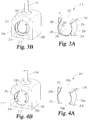
Figs. 3A-3B are perspective views of one embodiment of an exhaust flow directing device and of the directing device mounted in an inlet of the exhaust aftertreatment apparatus, respectively. -
Figs. 4A-4B are perspective views of another embodiment of an exhaust flow directing device and of the directing device mounted in an inlet of the exhaust aftertreatment apparatus, respectively - With reference to
Fig. 1 , there is illustrated anexemplary system 100 that includes anexhaust aftertreatment system 110.System 100 may be provided on any suitable application, such as a vehicle powered by anengine 102 such as a diesel engine, or on anengine 102 utilized in other applications such as power generation, pumping, marine, and locomotive systems.Engine 102 includes anintake system 104 through which charge air enters and anexhaust system 106 through which a flow of exhaust gas resulting from combustion exits, it being understood that not all details of these systems that are typically present are shown. -
Engine 102 includes a number of cylinders forming combustion chambers in which fuel combusts with the charge air that has entered throughintake system 104. The combustion process produces a significant amount of emissions, most prominent being nitric oxide (NO) and nitrogen dioxide (NO2), commonly known as NOx. Other emissions include particulates, carbon monoxide (CO), and hydrocarbons (HC). Before entering the atmosphere, however, the exhaust gas is treated by one or more aftertreatment devices in theexhaust aftertreatment system 110 to reduce or eliminate such emissions. - In one example, the
exhaust system 106 includes theexhaust aftertreatment system 110 having one or more selective catalytic reduction (SCR)catalysts 116, and one or more locations for receiving a reductant from areductant dosing system 120. Areductant injector 114 is mounted on a portion ofexhaust system 106 upstream ofSCR catalyst 116 with its outlet, or nozzle, arranged to spray reductant into theexhaust system 106 where it mixes with engine exhaust gas produced byengine 102.SCR catalyst 116 promotes a chemical reaction between the reductant and NOx in the exhaust gas that converts substantial amounts of NOx to reduce NOx emissions before the exhaust gas passes into the atmosphere. - The exhaust aftertreatment system further includes an exhaust
flow directing device 112 in the exhaust flow path upstream of thereductant injector 114. Exhaustflow directing device 112 directs at least a portion of the exhaust flow toward thereductant injector 114 to efficiently mix the exhaust gas and the reductant sprayed into theexhaust system 106 by thereductant injector 114. The efficient mixing of the exhaust gas and the reductant reduces reductant deposit formation inexhaust system 106. Reducing the reductant deposit formation increases the exhaust aftertreatment system's reliability and ability to meet emission requirements. The exhaustflow directing device 112 is further detailed below. - The
aftertreatment system 110 may include one or more other aftertreatment components not shown, such as diesel oxidation catalysts, diesel particulate filters, an ammonia oxidation catalyst, and various temperature, pressure and exhaust gas constituent sensors.Exhaust system 106 may also include various components not shown, such an exhaust gas recirculation system, a turbocharger system, coolers, and other components connectingexhaust system 106 tointake system 104. -
Reductant dosing system 120 receives reductant from a reductant storage tank (not shown) and provides the reductant to theexhaust system 106 viainjector 114 or any suitable device or arrangement for injection or delivery of reductant to a decomposition chamber or directly to theexhaust system 106. As used herein, an injector includes any nozzle, static device, electronically controllable device, and/or mechanical actuator that provides an outlet for reductant delivery into the exhaust flow path. One example of a suitable reductant is a diesel exhaust fluid (DEF) which comprises a solution of 32.5% high purity urea and 67.5% deionized water. It shall be appreciated, however, that any suitable reductant for injection into an exhaust system withdosing system 120 may also be utilized. -
Fig. 2 illustrates an exemplary embodiment of anexhaust aftertreatment apparatus 200. Theaftertreatment apparatus 200 includes ahousing 204 that defines adecomposition chamber 210 and asubstrate chamber 230. In other embodiments,decomposition chamber 210 andsubstrate chamber 230 are defined by separate housings. The separate housings can be connected directly to one another or connected to one another by a conduit. Thedecomposition chamber 210 includes aninlet 212 for receiving anexhaust stream 202 produced from operation of theengine 102. An exhaustflow directing device 214 is located in oradjacent inlet 212 in theexhaust stream 202 flow path. Exhaustflow directing device 214 can be secured to inlet 212 by one ormore braces 216. In other embodiments, exhaustflow directing device 214 is mounted to a wall ofhousing 204, an exhaust conduit connected toinlet 212, or other structure of the exhaust system. Thedecomposition chamber 210 is coupled to thereductant system 120 by at least one reductant injector opening 222 of thereductant injector 114 that is configured to inject a reductant into theexhaust stream 202 through the reductant injector opening 222. - The
substrate chamber 230 is connected todecomposition chamber 210 through asubstrate chamber inlet 232 for receiving the mixed reductant andexhaust stream 202 fromdecomposition chamber 210 into the substrate chamber.Inlet 232 is offset axially from theinlet 212 so that theexhaust stream 202 travels from a first side ofdecomposition chamber 210 wherereductant opening 222 is located to an opposite side ofdecomposition chamber 210 for delivery of the mixed reductant and exhaust stream tosubstrate chamber 230. The offset arrangement provides a compact flow path that promotes mixing of the reductant and exhaust gas before delivery tosubstrate chamber 230. Thesubstrate chamber 230 further includes one ormore SCR catalysts 234 for promoting a chemical reaction between the reductant and NOx in theexhaust stream 202. Theexhaust stream 202 exits housing 204 and thesubstrate chamber 230 through thesubstrate chamber outlet 236. Other arrangements of one ormore SCR catalysts 234 insubstrate chamber 230 are also contemplated.Outlet 236 is offset frominlet 232 and adjacent the same side ofhousing 204 asinlet 212, although other arrangements are not precluded. - The exhaust
flow directing device 214 is mounted in thedecomposition chamber inlet 212 to create a space between an outer surface of the exhaustflow directing device 214 and an inner surface of thedecomposition chamber inlet 212. The space defines afirst flow path 240 where at least a portion of the exhaust stream is directed through the space. Asecond flow path 242 is defined through the interior of the exhaustflow directing device 214. Thesecond flow path 242 directs a second portion of the exhaust stream toward thereductant injector opening 222, creating a shear force across thereductant opening 222 which reduces the formation of reductant deposits. Additionally, the first andsecond flow paths decomposition chamber 210, further reducing the formation of reductant deposits, without decreasing the flow of theexhaust stream 202 to theSCR catalysts 234. - The
exhaust aftertreatment apparatus 200 illustrated inFig. 2 shows theexhaust stream 202 entering adecomposition chamber inlet 212 that is located on the end of thedecomposition chamber 210. It should be appreciated that the exhaustflow directing device 214 can be configured to accommodate alternative means ofexhaust stream 202 entry into thedecomposition chamber 210, depending on where thedecomposition chamber inlet 212 is positioned relative to thehousing 204 and theoutlet 236. For example,inlet 212 can be located on the side ofhousing 204. As used herein, an end inlet and end outlet, such as shown inFig. 2 , are oriented in the same direction relative to the exhaust flow throughhousing 204, while a side inlet and end outlet are located in transverse orientations relative to one another onhousing 204. However, any combination of inlets and outlets are contemplated, including end inlet and side outlet, side inlet and side outlet, etc. The exhaustflow directing device 314 inFigs. 4A-4B , discussed in further detail below, is an example embodiment used in a side inlet, end outlet type exhaust flow directing device, although exhaustflow directing device 214 could be used in a side inlet arrangement and exhaustflow directing device 314 ofFigs. 4A-4B could be used in an end inlet arrangement. -
Figs. 3A-3B illustrate further details of exhaustflow directing device 214. Exhaustflow directing device 214 includes abody 250 that has a conical frustum shape extending between afirst end 260 and an oppositesecond end 262.Second end 262 is located towarddecomposition chamber 230 andfirst end 260 is located away fromsecond end 262 to receive the exhaust flow.Body 250 includes aninner surface 252 defining thesecond flow path 242 and an oppositeouter surface 254 that, with the inner surface ofinlet 212, definesfirst flow path 240.Body 250 further defines an opening or slot 258 along one side thereof that is oriented toward reductant opening 222 to direct at least a portion of exhaust flow towardreductant opening 222.Slot 258 provides an opening through whichfirst flow path 240 andsecond flow path 242 communicate with one another.Braces 216 are connected toouter surface 254 and project radially outwardly therefrom for mounting with, for example,inlet 212 to spaceouter wall surface 254 from the inner surface ofinlet 212 and form and maintain the opening offirst flow channel 240. - Referring to
Figs. 4A-4B , another embodiment exhaustflow directing device 314 is shown that is similar to exhaustflow targeting device 214. Exhaust flow targeting device includes first andsecond wall segments opposite slots Braces 216 are secured to respective ones of thewall segments flow directing device 314 ininlet 212 in a manner similar to that discussed above with respect to exhaustflow directing device 214, such as shown inFig. 4B .Opposite slots first flow path 240 andsecond flow path 242 at opposite sides of exhaustflow directing device 314. - Various aspects of the system and apparatus are disclosed herein. For example, one aspect involves a system that includes an internal combustion engine operable to produce an exhaust stream and an aftertreatment exhaust component assembly connected to the engine to receive the exhaust, the aftertreatment exhaust component assembly includes a decomposition chamber connected to a reduction assembly, the reduction assembly includes a catalyst downstream of the decomposition chamber, the decomposition chamber includes an inlet upstream of the connection with the reductant assembly and further includes an exhaust flow targeting device at the inlet, and the exhaust flow targeting device is configured to define a first exhaust flow path through the exhaust flow targeting device at the reductant system connection, and further configured to define a second exhaust flow path between an outer wall of the exhaust flow targeting device and the inlet.
- In a further embodiment, the exhaust flow directing device is configured to direct exhaust flow toward the connection with reductant source. In still a further embodiment, the exhaust flow directing device includes a frusto-conically shaped body that expands outwardly in a direction of the exhaust flow. In yet a further embodiment, the body includes at least one slot forming a side opening of the body oriented toward the reductant opening. In yet still a further embodiment, the body includes a second slot forming a second side opening opposite the side opening. In another further embodiment, the body is formed by first and second wall segments that extend between the side openings.
- In one embodiment of the system, the reductant system comprises a reductant storage tank, a reductant injector connected to the storage tank via a pump, and a doser tip connected to the reductant injector configured to be in the exhaust stream downstream of the exhaust flow targeting device.
- Another example includes an exhaust emission aftertreatment apparatus that includes at least one housing defining a decomposition chamber fluidly coupled with a substrate chamber, wherein the substrate chamber houses a catalyst and the decomposition chamber is positioned upstream of the substrate chamber, the housing including an inlet into the decomposition chamber and a reductant opening downstream of the inlet for providing a flow of reductant into the decomposition chamber; and an exhaust flow directing device positioned at least partially in the inlet, wherein the exhaust flow directing device is configured relative to the inlet to direct a first portion of the exhaust flow along a first flow path that extends through the exhaust flow directing device into the decomposition chamber and a second portion of the exhaust flow along a second flow path that extends around the exhaust flow directing device into the decomposition chamber.
- In one refinement of the apparatus, the exhaust flow directing device is connected to and spaced inwardly from an inner surface of the inlet by a plurality of braces to define the second flow path. In a further refinement, the exhaust flow directing device defines an outwardly tapered configuration for the first flow path in a direction of exhaust flow into the decomposition chamber. In another refinement, the exhaust flow directing device defines a first slot oriented toward the reductant opening and the slot extends between the first flow path and the second flow path. In yet another refinement, the exhaust flow directing device defines a second slot opposite the first slot, wherein each of the first and second slots extends between the first and second flow paths. In still yet a further refinement, the exhaust flow directing device defines a conical frustum shape that is oriented to expand in a direction of the exhaust flow into the decomposition chamber.
- In yet a further refinement, the exhaust flow directing device includes an inner end oriented toward the decomposition chamber and an oppositely facing outer end, and a slot that extends through a wall of the exhaust flow directing device from the inner end to the outer end, wherein the slot is oriented toward the opening for the reductant. The exhaust flow directing device includes a first wall segment and a second wall segment, wherein a first end of each of the first and second walls segments are separated by the slot and an opposite second end of the first and second wall segments are separated by a second slot. In still a further refinement, the exhaust flow directing device is configured to direct exhaust flow toward the reductant opening. In yet still further refinements, the decomposition chamber and the substrate chamber are defined by a common housing or by separate housings.
- In another embodiment of the apparatus for receiving an exhaust flow, the apparatus includes at least one housing defining a decomposition chamber fluidly coupled with a substrate chamber, wherein the substrate chamber houses a catalyst and the decomposition chamber is positioned upstream of the substrate chamber, the housing including an inlet into the decomposition chamber and a reductant opening downstream of the inlet for providing a flow of reductant into the decomposition chamber; and an exhaust flow directing device positioned at least partially in the inlet, wherein the exhaust flow directing device includes a frusto-conically shaped body that expands in a direction of the exhaust flow and the body includes at least one slot forming a side opening of the body oriented toward the reductant opening.
- In a refinement of the embodiment, the body includes a second slot forming a second side opening opposite the side opening. In a further refinement of the embodiment, the body is formed by first and second wall segments that extend between the side openings.
- While the invention has been illustrated and described in detail in the drawings and foregoing description, the same is to be considered as illustrative and not restrictive in character, it being understood that only certain exemplary embodiments have been shown and described and that all changes and modifications that come within the spirit of the inventions are desired to be protected.
- It should be understood that while the use of words such as preferable, preferably, preferred or more preferred utilized in the description above indicate that the feature so described may be more desirable, it nonetheless may not be necessary and embodiments lacking the same may be contemplated as within the scope of the invention, the scope being defined by the claims that follow. In reading the claims, it is intended that when words such as "a," "an," "at least one," or "at least one portion" are used there is no intention to limit the claim to only one item unless specifically stated to the contrary in the claim. When the language "at least a portion" and/or "a portion" is used the item can include a portion and/or the entire item unless specifically stated to the contrary.
Claims (12)
- An aftertreatment assembly, comprising:a decomposition chamber (210) having a reductant opening (222) to receive reductant from a reductant source, the decomposition chamber (210) including an inlet (212) upstream of the reductant opening (222);a catalyst (234) downstream of the decomposition chamber (210); andan exhaust flow directing device (214) at the inlet (212) and positioned upstream of the reductant opening (222), the exhaust flow directing device (214) defining:
a first exhaust flow path (242) through the exhaust flow directing device (214) and a second exhaust flow path (240) between an outer wall of the exhaust flow directing device (214) and the inlet (212), characterized in that the exhaust flow directing device (214) comprises a slot (258; 358a) extending from a first end (260) of the exhaust flow directing device (214), at which exhaust flow is received, to a second end (262) of the exhaust flow directing device (214), which is located opposite the first end (260), the slot (258; 358a) being oriented toward a side of the decomposition chamber (230) in which the reductant opening (222) is located. - The aftertreatment assembly of claim 1, further comprising a reductant system (120) which comprises a reductant storage tank for storing the reductant source and a reductant injector (114) connected to the storage tank, the reductant injector (114) positioned to inject reductant into the decomposition chamber (210) downstream of the exhaust flow directing device (214).
- The aftertreatment assembly of claim 1 or claim 2, wherein the exhaust flow directing device (214) includes a frusto-conically shaped body (250) that expands in a direction of the exhaust flow.
- The aftertreatment assembly of claim 3, wherein the frusto-conically shaped body (250) includes a second slot (358b) opposite the slot (358a).
- The after treatment assembly of claim 4,wherein the frusto-conically shaped body (250) is formed by first (350a) and second (350b) wall segments that extend between the slots (358a, 358b).
- The aftertreatment assembly of claim 1, further comprising:at least one housing (204) defining the decomposition chamber (210) fluidly coupled with a substrate chamber (230), wherein the substrate chamber (230) houses the catalyst and the decomposition chamber (210) is positioned upstream of the substrate chamber (230), the housing (204) including the inlet (212) into the decomposition chamber (210); andwherein the first flow path (242) extends through the exhaust flow directing device (214) into the decomposition chamber (210) and the second flow path (240) extends around the exhaust flow directing device (214) into the decomposition chamber (210).
- The aftertreatment assembly of claim 6, wherein the exhaust flow directing device (214) is connected to and spaced inwardly from an inner surface of the inlet (212) by a plurality of braces (216) to define the second flow path (242).
- The aftertreatment assembly of claim 6 or claim 7, wherein the exhaust flow directing device (214) defines an outwardly tapered configuration for the first flow path (240) in a direction of exhaust flow into the decomposition chamber (210).
- The aftertreatment assembly of any of claims 6 to 8, wherein the exhaust flow directing device (214) defines a conical frustum shape that is oriented to expand in a direction of the exhaust flow into the decomposition chamber (210).
- The aftertreatment assembly of any of claims 6 to 9, wherein the exhaust flow directing device (214) includes a first wall segment (350a) and a second wall segment (350b), wherein a first end of each of the first (350a) and second (350b) walls segments are separated by the slot (358a) and an opposite second end of the first (350a) and second (350b) wall segments are separated by a second slot (358b).
- The aftertreatment assembly of any of claims 6 to 10,
wherein the decomposition chamber (210) and the substrate chamber (230) are defined by a common housing (204). - A system comprising the aftertreatment assembly of claim 1, the system including:an internal combustion engine (102) operable to produce an exhaust stream (202); anda reductant system (120) including a reductant source;wherein the aftertreatment assembly is connected to the engine (102) to receive the exhaust stream (202) from the engine (102).
Applications Claiming Priority (1)
| Application Number | Priority Date | Filing Date | Title |
|---|---|---|---|
| US14/050,614 US9057312B2 (en) | 2013-10-10 | 2013-10-10 | System and apparatus for reducing reductant deposit formation in exhaust aftertreatment systems |
Publications (2)
| Publication Number | Publication Date |
|---|---|
| EP2860369A1 EP2860369A1 (en) | 2015-04-15 |
| EP2860369B1 true EP2860369B1 (en) | 2018-12-05 |
Family
ID=51687848
Family Applications (1)
| Application Number | Title | Priority Date | Filing Date |
|---|---|---|---|
| EP14187835.5A Active EP2860369B1 (en) | 2013-10-10 | 2014-10-06 | System and device for reducing reductant deposit formation in exhaust aftertreatment systems |
Country Status (4)
| Country | Link |
|---|---|
| US (1) | US9057312B2 (en) |
| EP (1) | EP2860369B1 (en) |
| CN (1) | CN104564262B (en) |
| RU (1) | RU2643260C2 (en) |
Families Citing this family (18)
| Publication number | Priority date | Publication date | Assignee | Title |
|---|---|---|---|---|
| DE202008001547U1 (en) | 2007-07-24 | 2008-04-10 | Emcon Technologies Germany (Augsburg) Gmbh | Assembly for introducing a reducing agent into the exhaust pipe of an exhaust system of an internal combustion engine |
| US9995193B2 (en) * | 2013-07-25 | 2018-06-12 | Faurecia Emissions Control Technologies Usa, Llc | Mixer with swirl box for a vehicle exhaust system |
| KR101921920B1 (en) | 2014-06-03 | 2018-11-27 | 포레시아 이미션스 컨트롤 테크놀로지스, 유에스에이, 엘엘씨 | Mixer and doser cone assembly |
| US10493410B2 (en) * | 2015-01-09 | 2019-12-03 | Cummins Emission Solutions Inc. | Selective catalytic reduction with integrated decomposition chamber with exhaust flow swirl generating design |
| DE102015201193B3 (en) * | 2015-01-23 | 2016-06-30 | Continental Automotive Gmbh | Exhaust gas purification component for cleaning the exhaust gases of an internal combustion engine |
| US9828897B2 (en) | 2015-04-30 | 2017-11-28 | Faurecia Emissions Control Technologies Usa, Llc | Mixer for a vehicle exhaust system |
| WO2016176076A1 (en) | 2015-04-30 | 2016-11-03 | Faurecia Emissions Control Technologies, Usa, Llc | Full rotation mixer |
| WO2016176078A1 (en) | 2015-04-30 | 2016-11-03 | Faurecia Emissions Control Technologies, Usa, Llc | Mixer with integrated doser cone |
| US9719397B2 (en) * | 2015-04-30 | 2017-08-01 | Faurecia Emissions Control Technologies Usa, Llc | Mixer with integrated doser cone |
| KR102414068B1 (en) | 2016-10-21 | 2022-06-28 | 포레시아 이미션스 컨트롤 테크놀로지스, 유에스에이, 엘엘씨 | reducing agent mixer |
| US10337380B2 (en) | 2017-07-07 | 2019-07-02 | Faurecia Emissions Control Technologies, Usa, Llc | Mixer for a vehicle exhaust system |
| GB2586752B (en) | 2018-04-02 | 2022-07-27 | Cummins Emission Solutions Inc | Aftertreatment system including noise reducing components |
| US10316721B1 (en) | 2018-04-23 | 2019-06-11 | Faurecia Emissions Control Technologies, Usa, Llc | High efficiency mixer for vehicle exhaust system |
| US10287948B1 (en) | 2018-04-23 | 2019-05-14 | Faurecia Emissions Control Technologies, Usa, Llc | High efficiency mixer for vehicle exhaust system |
| WO2020009694A1 (en) | 2018-07-03 | 2020-01-09 | Cummins Emission Solutions Inc. | Body mixing decomposition reactor |
| US10787946B2 (en) | 2018-09-19 | 2020-09-29 | Faurecia Emissions Control Technologies, Usa, Llc | Heated dosing mixer |
| EP4245972A1 (en) | 2022-03-18 | 2023-09-20 | Winterthur Gas & Diesel Ltd. | Exhaust gas after treatment device |
| US12540569B2 (en) | 2023-09-07 | 2026-02-03 | Cummins Emission Solutions Inc. | Mixing body assembly for exhaust aftertreatment system |
Family Cites Families (26)
| Publication number | Priority date | Publication date | Assignee | Title |
|---|---|---|---|---|
| US4054418A (en) | 1975-11-10 | 1977-10-18 | E. I. Du Pont De Nemours And Company | Catalytic abatement system |
| US6722123B2 (en) | 2001-10-17 | 2004-04-20 | Fleetguard, Inc. | Exhaust aftertreatment device, including chemical mixing and acoustic effects |
| US6745562B2 (en) * | 2002-09-16 | 2004-06-08 | Kleenair Systems, Inc. | Diverter for catalytic converter |
| JP2004316428A (en) * | 2003-02-26 | 2004-11-11 | Ngk Insulators Ltd | Method and program for predicting soot deposition quantity on exhaust gas emission filter |
| JP4082347B2 (en) * | 2003-12-18 | 2008-04-30 | トヨタ自動車株式会社 | Plasma injector and exhaust gas purification system |
| ES2382128T3 (en) | 2004-07-16 | 2012-06-05 | Nissan Diesel Motor Co., Ltd. | Engine exhaust emission purification device |
| US8463529B2 (en) * | 2004-09-17 | 2013-06-11 | Eaton Corporation | System and method of operating internal combustion engines at fuel rich low-temperature- combustion mode as an on-board reformer for solid oxide fuel cell-powered vehicles |
| US8173088B2 (en) * | 2010-02-24 | 2012-05-08 | International Engine Intellectual Property Company, Llc | Method, system and apparatus for liquid injection into a gas system |
| US20070144158A1 (en) * | 2005-12-22 | 2007-06-28 | Girard James W | Exhaust dispersion device |
| US7748212B2 (en) | 2007-03-09 | 2010-07-06 | Cummins Filtration Ip, Inc. | Exhaust aftertreatment system with flow distribution |
| US7908845B2 (en) * | 2007-04-16 | 2011-03-22 | GM Global Technology Operations LLC | Mixing apparatus for an exhaust after-treatment system |
| JP4978344B2 (en) * | 2007-07-03 | 2012-07-18 | トヨタ自動車株式会社 | Exhaust fuel addition control device for internal combustion engine |
| JP2009185624A (en) * | 2008-02-04 | 2009-08-20 | Nissan Motor Co Ltd | Fuel reformer for power engine and fuel reforming method |
| JP5053163B2 (en) * | 2008-04-28 | 2012-10-17 | 本田技研工業株式会社 | Exhaust gas purification device for internal combustion engine |
| US8297050B2 (en) * | 2008-07-11 | 2012-10-30 | GM Global Technology Operations LLC | Nozzle diffuser mixer |
| CN201314265Y (en) * | 2008-09-04 | 2009-09-23 | 李媺莹 | Energy-saving emission-reducing fiber suite |
| DE102008048796A1 (en) * | 2008-09-24 | 2010-03-25 | Emitec Gesellschaft Für Emissionstechnologie Mbh | Emission control system for diesel engines |
| US8539757B2 (en) | 2009-01-16 | 2013-09-24 | Toyota Jidosha Kabushiki Kaisha | Exhaust purification apparatus for internal combustion engine |
| US8240137B2 (en) | 2009-10-27 | 2012-08-14 | Cummins Filtration Ip, Inc. | Reductant injection and decomposition system |
| US8683790B2 (en) * | 2009-11-10 | 2014-04-01 | GM Global Technology Operations LLC | Nozzle diffuser mixer |
| WO2011087527A1 (en) * | 2010-01-12 | 2011-07-21 | Donaldson Company, Inc. | Flow device for exhaust treatment system |
| SE535219C2 (en) | 2010-10-06 | 2012-05-29 | Scania Cv Abp | Arrangement for introducing a liquid medium into exhaust gases from an internal combustion engine |
| US8438839B2 (en) | 2010-10-19 | 2013-05-14 | Tenneco Automotive Operating Company Inc. | Exhaust gas stream vortex breaker |
| US20120151902A1 (en) * | 2010-12-16 | 2012-06-21 | Caterpillar Inc. | Biased reductant mixer |
| US8756921B2 (en) | 2011-01-10 | 2014-06-24 | Paccar Inc | Reductant delivery device |
| US8677738B2 (en) * | 2011-09-08 | 2014-03-25 | Tenneco Automotive Operating Company Inc. | Pre-injection exhaust flow modifier |
-
2013
- 2013-10-10 US US14/050,614 patent/US9057312B2/en active Active
-
2014
- 2014-10-03 RU RU2014140113A patent/RU2643260C2/en active
- 2014-10-06 EP EP14187835.5A patent/EP2860369B1/en active Active
- 2014-10-10 CN CN201410530867.8A patent/CN104564262B/en active Active
Non-Patent Citations (1)
| Title |
|---|
| None * |
Also Published As
| Publication number | Publication date |
|---|---|
| RU2643260C2 (en) | 2018-01-31 |
| CN104564262A (en) | 2015-04-29 |
| US20150101318A1 (en) | 2015-04-16 |
| US9057312B2 (en) | 2015-06-16 |
| RU2014140113A (en) | 2016-04-20 |
| CN104564262B (en) | 2018-01-16 |
| EP2860369A1 (en) | 2015-04-15 |
Similar Documents
| Publication | Publication Date | Title |
|---|---|---|
| US9057312B2 (en) | System and apparatus for reducing reductant deposit formation in exhaust aftertreatment systems | |
| US7776280B2 (en) | Method and apparatus for selective catalytic reduction of NOx | |
| US9410460B2 (en) | Exhaust system of an internal combustion engine | |
| EP3030767B1 (en) | Method, apparatus and system for aftertreatment of exhaust gas | |
| KR102227207B1 (en) | Scr system | |
| US8997463B2 (en) | Reductant delivery unit for automotive selective catalytic reduction with reducing agent heating | |
| US20100139258A1 (en) | Exhaust mixer with backward flow | |
| EP2960456B1 (en) | Angled and compact exhaust gas aftertreatment device | |
| US7200989B2 (en) | Apparatus and method for cleaning exhaust gas from an internal combustion engine | |
| CN203856551U (en) | Mixer module and exhaust cleaning module | |
| US9957868B2 (en) | Centerline injection system for liquid-only reductant delivery | |
| US20150113966A1 (en) | Aftertreatment systems with reduced n2o generation | |
| US20090084088A1 (en) | Exhaust gas purifying system | |
| CN103821595B (en) | Reductant delivery unit and method for reducing sedimentation formation in same | |
| CN104234801A (en) | An exhaust gas sampling device | |
| CN204984552U (en) | A exhaust after treatment system for engine | |
| CN103998736B (en) | There is the Fluid sprayer of the assignment of traffic of equilibrium | |
| EP3489480B1 (en) | Scr mixer and scr device comprising same | |
| CN111550300B (en) | Mixer for an exhaust system | |
| CN115335591B (en) | Exhaust denitration device | |
| US9470132B2 (en) | Compact radial exterior exhaust assisted decomposition reactor pipe | |
| US20210131327A1 (en) | Dosing module for use in aftertreatment systems for internal combustion engines | |
| CN112443376A (en) | mixing device | |
| JP2012002084A (en) | Guide for guiding exhaust flow, and exhaust emission control device equipped with the same |
Legal Events
| Date | Code | Title | Description |
|---|---|---|---|
| PUAI | Public reference made under article 153(3) epc to a published international application that has entered the european phase |
Free format text: ORIGINAL CODE: 0009012 |
|
| 17P | Request for examination filed |
Effective date: 20141006 |
|
| AK | Designated contracting states |
Kind code of ref document: A1 Designated state(s): AL AT BE BG CH CY CZ DE DK EE ES FI FR GB GR HR HU IE IS IT LI LT LU LV MC MK MT NL NO PL PT RO RS SE SI SK SM TR |
|
| AX | Request for extension of the european patent |
Extension state: BA ME |
|
| R17P | Request for examination filed (corrected) |
Effective date: 20150923 |
|
| RBV | Designated contracting states (corrected) |
Designated state(s): AL AT BE BG CH CY CZ DE DK EE ES FI FR GB GR HR HU IE IS IT LI LT LU LV MC MK MT NL NO PL PT RO RS SE SI SK SM TR |
|
| STAA | Information on the status of an ep patent application or granted ep patent |
Free format text: STATUS: EXAMINATION IS IN PROGRESS |
|
| 17Q | First examination report despatched |
Effective date: 20171114 |
|
| REG | Reference to a national code |
Ref country code: DE Ref legal event code: R079 Ref document number: 602014037314 Country of ref document: DE Free format text: PREVIOUS MAIN CLASS: F01N0003200000 Ipc: F01N0003280000 |
|
| RIC1 | Information provided on ipc code assigned before grant |
Ipc: F01N 3/20 20060101ALI20180406BHEP Ipc: F01N 3/28 20060101AFI20180406BHEP |
|
| GRAP | Despatch of communication of intention to grant a patent |
Free format text: ORIGINAL CODE: EPIDOSNIGR1 |
|
| STAA | Information on the status of an ep patent application or granted ep patent |
Free format text: STATUS: GRANT OF PATENT IS INTENDED |
|
| INTG | Intention to grant announced |
Effective date: 20180522 |
|
| GRAS | Grant fee paid |
Free format text: ORIGINAL CODE: EPIDOSNIGR3 |
|
| GRAA | (expected) grant |
Free format text: ORIGINAL CODE: 0009210 |
|
| STAA | Information on the status of an ep patent application or granted ep patent |
Free format text: STATUS: THE PATENT HAS BEEN GRANTED |
|
| AK | Designated contracting states |
Kind code of ref document: B1 Designated state(s): AL AT BE BG CH CY CZ DE DK EE ES FI FR GB GR HR HU IE IS IT LI LT LU LV MC MK MT NL NO PL PT RO RS SE SI SK SM TR |
|
| REG | Reference to a national code |
Ref country code: GB Ref legal event code: FG4D |
|
| REG | Reference to a national code |
Ref country code: CH Ref legal event code: EP |
|
| REG | Reference to a national code |
Ref country code: AT Ref legal event code: REF Ref document number: 1073360 Country of ref document: AT Kind code of ref document: T Effective date: 20181215 |
|
| REG | Reference to a national code |
Ref country code: IE Ref legal event code: FG4D |
|
| REG | Reference to a national code |
Ref country code: DE Ref legal event code: R096 Ref document number: 602014037314 Country of ref document: DE |
|
| REG | Reference to a national code |
Ref country code: NL Ref legal event code: MP Effective date: 20181205 |
|
| REG | Reference to a national code |
Ref country code: AT Ref legal event code: MK05 Ref document number: 1073360 Country of ref document: AT Kind code of ref document: T Effective date: 20181205 |
|
| REG | Reference to a national code |
Ref country code: LT Ref legal event code: MG4D |
|
| PG25 | Lapsed in a contracting state [announced via postgrant information from national office to epo] |
Ref country code: AT Free format text: LAPSE BECAUSE OF FAILURE TO SUBMIT A TRANSLATION OF THE DESCRIPTION OR TO PAY THE FEE WITHIN THE PRESCRIBED TIME-LIMIT Effective date: 20181205 Ref country code: FI Free format text: LAPSE BECAUSE OF FAILURE TO SUBMIT A TRANSLATION OF THE DESCRIPTION OR TO PAY THE FEE WITHIN THE PRESCRIBED TIME-LIMIT Effective date: 20181205 Ref country code: LT Free format text: LAPSE BECAUSE OF FAILURE TO SUBMIT A TRANSLATION OF THE DESCRIPTION OR TO PAY THE FEE WITHIN THE PRESCRIBED TIME-LIMIT Effective date: 20181205 Ref country code: HR Free format text: LAPSE BECAUSE OF FAILURE TO SUBMIT A TRANSLATION OF THE DESCRIPTION OR TO PAY THE FEE WITHIN THE PRESCRIBED TIME-LIMIT Effective date: 20181205 Ref country code: NO Free format text: LAPSE BECAUSE OF FAILURE TO SUBMIT A TRANSLATION OF THE DESCRIPTION OR TO PAY THE FEE WITHIN THE PRESCRIBED TIME-LIMIT Effective date: 20190305 Ref country code: LV Free format text: LAPSE BECAUSE OF FAILURE TO SUBMIT A TRANSLATION OF THE DESCRIPTION OR TO PAY THE FEE WITHIN THE PRESCRIBED TIME-LIMIT Effective date: 20181205 Ref country code: ES Free format text: LAPSE BECAUSE OF FAILURE TO SUBMIT A TRANSLATION OF THE DESCRIPTION OR TO PAY THE FEE WITHIN THE PRESCRIBED TIME-LIMIT Effective date: 20181205 Ref country code: BG Free format text: LAPSE BECAUSE OF FAILURE TO SUBMIT A TRANSLATION OF THE DESCRIPTION OR TO PAY THE FEE WITHIN THE PRESCRIBED TIME-LIMIT Effective date: 20190305 |
|
| PG25 | Lapsed in a contracting state [announced via postgrant information from national office to epo] |
Ref country code: AL Free format text: LAPSE BECAUSE OF FAILURE TO SUBMIT A TRANSLATION OF THE DESCRIPTION OR TO PAY THE FEE WITHIN THE PRESCRIBED TIME-LIMIT Effective date: 20181205 Ref country code: SE Free format text: LAPSE BECAUSE OF FAILURE TO SUBMIT A TRANSLATION OF THE DESCRIPTION OR TO PAY THE FEE WITHIN THE PRESCRIBED TIME-LIMIT Effective date: 20181205 Ref country code: GR Free format text: LAPSE BECAUSE OF FAILURE TO SUBMIT A TRANSLATION OF THE DESCRIPTION OR TO PAY THE FEE WITHIN THE PRESCRIBED TIME-LIMIT Effective date: 20190306 Ref country code: RS Free format text: LAPSE BECAUSE OF FAILURE TO SUBMIT A TRANSLATION OF THE DESCRIPTION OR TO PAY THE FEE WITHIN THE PRESCRIBED TIME-LIMIT Effective date: 20181205 |
|
| PG25 | Lapsed in a contracting state [announced via postgrant information from national office to epo] |
Ref country code: NL Free format text: LAPSE BECAUSE OF FAILURE TO SUBMIT A TRANSLATION OF THE DESCRIPTION OR TO PAY THE FEE WITHIN THE PRESCRIBED TIME-LIMIT Effective date: 20181205 |
|
| PG25 | Lapsed in a contracting state [announced via postgrant information from national office to epo] |
Ref country code: PT Free format text: LAPSE BECAUSE OF FAILURE TO SUBMIT A TRANSLATION OF THE DESCRIPTION OR TO PAY THE FEE WITHIN THE PRESCRIBED TIME-LIMIT Effective date: 20190405 Ref country code: CZ Free format text: LAPSE BECAUSE OF FAILURE TO SUBMIT A TRANSLATION OF THE DESCRIPTION OR TO PAY THE FEE WITHIN THE PRESCRIBED TIME-LIMIT Effective date: 20181205 Ref country code: PL Free format text: LAPSE BECAUSE OF FAILURE TO SUBMIT A TRANSLATION OF THE DESCRIPTION OR TO PAY THE FEE WITHIN THE PRESCRIBED TIME-LIMIT Effective date: 20181205 Ref country code: IT Free format text: LAPSE BECAUSE OF FAILURE TO SUBMIT A TRANSLATION OF THE DESCRIPTION OR TO PAY THE FEE WITHIN THE PRESCRIBED TIME-LIMIT Effective date: 20181205 |
|
| PG25 | Lapsed in a contracting state [announced via postgrant information from national office to epo] |
Ref country code: SK Free format text: LAPSE BECAUSE OF FAILURE TO SUBMIT A TRANSLATION OF THE DESCRIPTION OR TO PAY THE FEE WITHIN THE PRESCRIBED TIME-LIMIT Effective date: 20181205 Ref country code: IS Free format text: LAPSE BECAUSE OF FAILURE TO SUBMIT A TRANSLATION OF THE DESCRIPTION OR TO PAY THE FEE WITHIN THE PRESCRIBED TIME-LIMIT Effective date: 20190405 Ref country code: RO Free format text: LAPSE BECAUSE OF FAILURE TO SUBMIT A TRANSLATION OF THE DESCRIPTION OR TO PAY THE FEE WITHIN THE PRESCRIBED TIME-LIMIT Effective date: 20181205 Ref country code: SM Free format text: LAPSE BECAUSE OF FAILURE TO SUBMIT A TRANSLATION OF THE DESCRIPTION OR TO PAY THE FEE WITHIN THE PRESCRIBED TIME-LIMIT Effective date: 20181205 Ref country code: EE Free format text: LAPSE BECAUSE OF FAILURE TO SUBMIT A TRANSLATION OF THE DESCRIPTION OR TO PAY THE FEE WITHIN THE PRESCRIBED TIME-LIMIT Effective date: 20181205 |
|
| REG | Reference to a national code |
Ref country code: DE Ref legal event code: R097 Ref document number: 602014037314 Country of ref document: DE |
|
| PLBE | No opposition filed within time limit |
Free format text: ORIGINAL CODE: 0009261 |
|
| STAA | Information on the status of an ep patent application or granted ep patent |
Free format text: STATUS: NO OPPOSITION FILED WITHIN TIME LIMIT |
|
| PG25 | Lapsed in a contracting state [announced via postgrant information from national office to epo] |
Ref country code: DK Free format text: LAPSE BECAUSE OF FAILURE TO SUBMIT A TRANSLATION OF THE DESCRIPTION OR TO PAY THE FEE WITHIN THE PRESCRIBED TIME-LIMIT Effective date: 20181205 Ref country code: SI Free format text: LAPSE BECAUSE OF FAILURE TO SUBMIT A TRANSLATION OF THE DESCRIPTION OR TO PAY THE FEE WITHIN THE PRESCRIBED TIME-LIMIT Effective date: 20181205 |
|
| 26N | No opposition filed |
Effective date: 20190906 |
|
| PG25 | Lapsed in a contracting state [announced via postgrant information from national office to epo] |
Ref country code: TR Free format text: LAPSE BECAUSE OF FAILURE TO SUBMIT A TRANSLATION OF THE DESCRIPTION OR TO PAY THE FEE WITHIN THE PRESCRIBED TIME-LIMIT Effective date: 20181205 |
|
| PG25 | Lapsed in a contracting state [announced via postgrant information from national office to epo] |
Ref country code: MC Free format text: LAPSE BECAUSE OF FAILURE TO SUBMIT A TRANSLATION OF THE DESCRIPTION OR TO PAY THE FEE WITHIN THE PRESCRIBED TIME-LIMIT Effective date: 20181205 |
|
| REG | Reference to a national code |
Ref country code: CH Ref legal event code: PL |
|
| PG25 | Lapsed in a contracting state [announced via postgrant information from national office to epo] |
Ref country code: LI Free format text: LAPSE BECAUSE OF NON-PAYMENT OF DUE FEES Effective date: 20191031 Ref country code: CH Free format text: LAPSE BECAUSE OF NON-PAYMENT OF DUE FEES Effective date: 20191031 Ref country code: LU Free format text: LAPSE BECAUSE OF NON-PAYMENT OF DUE FEES Effective date: 20191006 |
|
| REG | Reference to a national code |
Ref country code: BE Ref legal event code: MM Effective date: 20191031 |
|
| PG25 | Lapsed in a contracting state [announced via postgrant information from national office to epo] |
Ref country code: BE Free format text: LAPSE BECAUSE OF NON-PAYMENT OF DUE FEES Effective date: 20191031 |
|
| PG25 | Lapsed in a contracting state [announced via postgrant information from national office to epo] |
Ref country code: IE Free format text: LAPSE BECAUSE OF NON-PAYMENT OF DUE FEES Effective date: 20191006 Ref country code: FR Free format text: LAPSE BECAUSE OF NON-PAYMENT OF DUE FEES Effective date: 20191031 |
|
| PG25 | Lapsed in a contracting state [announced via postgrant information from national office to epo] |
Ref country code: CY Free format text: LAPSE BECAUSE OF FAILURE TO SUBMIT A TRANSLATION OF THE DESCRIPTION OR TO PAY THE FEE WITHIN THE PRESCRIBED TIME-LIMIT Effective date: 20181205 |
|
| PG25 | Lapsed in a contracting state [announced via postgrant information from national office to epo] |
Ref country code: MT Free format text: LAPSE BECAUSE OF FAILURE TO SUBMIT A TRANSLATION OF THE DESCRIPTION OR TO PAY THE FEE WITHIN THE PRESCRIBED TIME-LIMIT Effective date: 20181205 Ref country code: HU Free format text: LAPSE BECAUSE OF FAILURE TO SUBMIT A TRANSLATION OF THE DESCRIPTION OR TO PAY THE FEE WITHIN THE PRESCRIBED TIME-LIMIT; INVALID AB INITIO Effective date: 20141006 |
|
| PG25 | Lapsed in a contracting state [announced via postgrant information from national office to epo] |
Ref country code: MK Free format text: LAPSE BECAUSE OF FAILURE TO SUBMIT A TRANSLATION OF THE DESCRIPTION OR TO PAY THE FEE WITHIN THE PRESCRIBED TIME-LIMIT Effective date: 20181205 |
|
| P01 | Opt-out of the competence of the unified patent court (upc) registered |
Effective date: 20230510 |
|
| PGFP | Annual fee paid to national office [announced via postgrant information from national office to epo] |
Ref country code: DE Payment date: 20251029 Year of fee payment: 12 |
|
| PGFP | Annual fee paid to national office [announced via postgrant information from national office to epo] |
Ref country code: GB Payment date: 20251027 Year of fee payment: 12 |