EP2860036B1 - Printing press, printing machine and method for operating a printing press - Google Patents
Printing press, printing machine and method for operating a printing press Download PDFInfo
- Publication number
- EP2860036B1 EP2860036B1 EP13004852.3A EP13004852A EP2860036B1 EP 2860036 B1 EP2860036 B1 EP 2860036B1 EP 13004852 A EP13004852 A EP 13004852A EP 2860036 B1 EP2860036 B1 EP 2860036B1
- Authority
- EP
- European Patent Office
- Prior art keywords
- printing
- print heads
- ink
- axis
- Prior art date
- Legal status (The legal status is an assumption and is not a legal conclusion. Google has not performed a legal analysis and makes no representation as to the accuracy of the status listed.)
- Active
Links
- 238000007639 printing Methods 0.000 title claims description 183
- 238000000034 method Methods 0.000 title claims description 34
- 238000004140 cleaning Methods 0.000 claims description 41
- 230000002093 peripheral effect Effects 0.000 claims description 31
- 238000001035 drying Methods 0.000 claims description 22
- 230000001360 synchronised effect Effects 0.000 claims description 9
- 238000010438 heat treatment Methods 0.000 claims description 5
- 230000000977 initiatory effect Effects 0.000 claims description 4
- 238000007599 discharging Methods 0.000 claims description 2
- 239000002245 particle Substances 0.000 description 8
- 239000003086 colorant Substances 0.000 description 7
- 239000000443 aerosol Substances 0.000 description 5
- 238000012545 processing Methods 0.000 description 5
- 230000001419 dependent effect Effects 0.000 description 4
- 238000006073 displacement reaction Methods 0.000 description 4
- 238000007689 inspection Methods 0.000 description 4
- 238000013459 approach Methods 0.000 description 3
- 238000011161 development Methods 0.000 description 3
- 230000018109 developmental process Effects 0.000 description 3
- 238000007641 inkjet printing Methods 0.000 description 3
- 238000012423 maintenance Methods 0.000 description 3
- 239000003973 paint Substances 0.000 description 3
- 238000007789 sealing Methods 0.000 description 3
- 239000002904 solvent Substances 0.000 description 3
- 230000001133 acceleration Effects 0.000 description 2
- 230000006978 adaptation Effects 0.000 description 2
- 238000003491 array Methods 0.000 description 2
- 238000004049 embossing Methods 0.000 description 2
- 230000002452 interceptive effect Effects 0.000 description 2
- 238000010146 3D printing Methods 0.000 description 1
- 230000002745 absorbent Effects 0.000 description 1
- 239000002250 absorbent Substances 0.000 description 1
- 230000005540 biological transmission Effects 0.000 description 1
- 238000011109 contamination Methods 0.000 description 1
- 230000008878 coupling Effects 0.000 description 1
- 238000010168 coupling process Methods 0.000 description 1
- 238000005859 coupling reaction Methods 0.000 description 1
- 230000002950 deficient Effects 0.000 description 1
- 238000001514 detection method Methods 0.000 description 1
- 238000004090 dissolution Methods 0.000 description 1
- 230000002349 favourable effect Effects 0.000 description 1
- 238000011049 filling Methods 0.000 description 1
- 230000005484 gravity Effects 0.000 description 1
- 238000007373 indentation Methods 0.000 description 1
- 239000004922 lacquer Substances 0.000 description 1
- 238000011068 loading method Methods 0.000 description 1
- 239000000463 material Substances 0.000 description 1
- 238000002156 mixing Methods 0.000 description 1
- 230000003287 optical effect Effects 0.000 description 1
- 239000011253 protective coating Substances 0.000 description 1
- 230000001681 protective effect Effects 0.000 description 1
- 230000001105 regulatory effect Effects 0.000 description 1
- 238000000926 separation method Methods 0.000 description 1
- 238000012360 testing method Methods 0.000 description 1
- 239000002966 varnish Substances 0.000 description 1
Images


Classifications
-
- B—PERFORMING OPERATIONS; TRANSPORTING
- B41—PRINTING; LINING MACHINES; TYPEWRITERS; STAMPS
- B41J—TYPEWRITERS; SELECTIVE PRINTING MECHANISMS, i.e. MECHANISMS PRINTING OTHERWISE THAN FROM A FORME; CORRECTION OF TYPOGRAPHICAL ERRORS
- B41J3/00—Typewriters or selective printing or marking mechanisms characterised by the purpose for which they are constructed
- B41J3/54—Typewriters or selective printing or marking mechanisms characterised by the purpose for which they are constructed with two or more sets of type or printing elements
- B41J3/543—Typewriters or selective printing or marking mechanisms characterised by the purpose for which they are constructed with two or more sets of type or printing elements with multiple inkjet print heads
-
- B—PERFORMING OPERATIONS; TRANSPORTING
- B41—PRINTING; LINING MACHINES; TYPEWRITERS; STAMPS
- B41J—TYPEWRITERS; SELECTIVE PRINTING MECHANISMS, i.e. MECHANISMS PRINTING OTHERWISE THAN FROM A FORME; CORRECTION OF TYPOGRAPHICAL ERRORS
- B41J25/00—Actions or mechanisms not otherwise provided for
- B41J25/001—Mechanisms for bodily moving print heads or carriages parallel to the paper surface
-
- B—PERFORMING OPERATIONS; TRANSPORTING
- B41—PRINTING; LINING MACHINES; TYPEWRITERS; STAMPS
- B41J—TYPEWRITERS; SELECTIVE PRINTING MECHANISMS, i.e. MECHANISMS PRINTING OTHERWISE THAN FROM A FORME; CORRECTION OF TYPOGRAPHICAL ERRORS
- B41J3/00—Typewriters or selective printing or marking mechanisms characterised by the purpose for which they are constructed
- B41J3/407—Typewriters or selective printing or marking mechanisms characterised by the purpose for which they are constructed for marking on special material
- B41J3/4073—Printing on three-dimensional objects not being in sheet or web form, e.g. spherical or cubic objects
- B41J3/40733—Printing on cylindrical or rotationally symmetrical objects, e. g. on bottles
-
- B—PERFORMING OPERATIONS; TRANSPORTING
- B41—PRINTING; LINING MACHINES; TYPEWRITERS; STAMPS
- B41J—TYPEWRITERS; SELECTIVE PRINTING MECHANISMS, i.e. MECHANISMS PRINTING OTHERWISE THAN FROM A FORME; CORRECTION OF TYPOGRAPHICAL ERRORS
- B41J2/00—Typewriters or selective printing mechanisms characterised by the printing or marking process for which they are designed
- B41J2/005—Typewriters or selective printing mechanisms characterised by the printing or marking process for which they are designed characterised by bringing liquid or particles selectively into contact with a printing material
- B41J2/01—Ink jet
- B41J2/135—Nozzles
- B41J2/165—Preventing or detecting of nozzle clogging, e.g. cleaning, capping or moistening for nozzles
Definitions
- the invention relates to a printing machine with a printing device for printing on a peripheral surface of an object, with at least two printheads, each having at least one row of Farbdosierianan, especially ink nozzles, each of which is designed for an individual predefinable release of color to the object. Furthermore, the invention relates to a method for operating a printing press with a printing device.
- a printing device for printing on the surface of a three-dimensional object comprising an ink jet printing system with a plurality of circumferentially adjacent to each other at a fixed distance arranged individual print heads, which can be moved during the execution of the printing operation along an axis of rotation for the object to be printed to a helical Allowing printing of the article, wherein a pitch between adjacent nozzles of the individual print heads is greater than a resolution of the image to be applied to the printed image and wherein the desired resolution is achieved by the helical printing of the article.
- the EP 2 471 665 A1 discloses a marking and / or scanning head having a plurality of receiving spaces, in which individual marking and / or sensor devices can be arranged for marking and / or scanning an object, wherein the receiving spaces are arranged in at least two subarrays, wherein at least one subarray is movable and / or rotatable relative to at least one other subarray, wherein the marking and / or scanning head further comprises a holding frame, which are arranged at least two sub-arrays on a common mounting frame, which is movable and / or rotatable relative to the holding frame, the sub-arrays are each about an axis of rotation, which passes through the center of the corresponding sub-array rotatable and the receiving spaces of each sub-array are arranged in a plurality of rows and columns to form a two-dimensional array of receiving spaces.
- the US 2011/084995 A1 discloses an ink jet printing method comprising the steps of: performing a print job within a print area using two or more print units, the print units being determined to be active; Determining one of the printing units as the idle printing unit; Moving the idle printing unit from the printing area to a maintenance area; Moving a predetermined idle pressure unit from the maintenance area to the pressure area; Determining the previously named idle printing unit as active; and continuing execution of the print job using two or more print engines that are currently designated as active.
- a printing machine for printing on cylindrical hollow bodies in which an ink jet printing method is used and in which opposite to an ink jet print head, a cleaning arrangement is mounted, which is designed for a cleaning of the ink jet print head.
- the CH 695 555 A5 discloses a printing machine for three-dimensional printing objects, comprising a printing device for applying at least one colorant to a printing object and with a drying device for drying the colorant, the printing device having one or more print heads and wherein the print heads and the drying device are arranged such that the drying of Color medium of a printed image can be done before its completion.
- the object of the invention is to provide a printing machine and a method for operating a printing press with a printing device, with which a particularly efficient printing of a high-resolution object is made possible.
- the print head has a plurality of ink dosing elements arranged along an extension axis, wherein each of the ink dosing elements is designed for individual dispensing of color particles or drops of ink, in particular ink droplets.
- the Farbdosierieri are arranged at a constant pitch along the extension axis, so that each adjacent Farbdosierieri have a constant distance from each other.
- the along the extension axis arranged Farbdosieretti form a print line, wherein a print head can be equipped with one or alternatively with multiple print lines, wherein a plurality of print lines are preferably arranged parallel to each other and with the same distance.
- a relative movement of a first print head relative to a second print head is made possible.
- This relative movement can influence which position the ink metering elements of the first print head occupy along the extension axis relative to the ink metering elements of the second print head.
- the Farbdosierimplantation the first print head are offset with respect to the extension axis by an amount relative to the Farbdosier instituten the second print head, which corresponds to 50 percent of the pitch of the Farbdosier institute.
- an adjustment of the position of the ink metering elements to print tracks can be achieved which have different slopes due to different requirements for the resolution of the print image to be generated and / or due to different diameters of the articles to be printed .
- an adjustment of the pitch for the helical print track must be achieved, depending on the desired resolution for the print image to be generated and depending on the diameter of the article, which is achieved by adjusting the relative position of the print heads by relative movement the extension axis can be guaranteed to each other.
- a change in the resolution of the printed image along the extension axis can also be provided during the execution of a printing operation, which is of interest, for example, if partial regions of the printed image are to be produced with higher resolution than other regions of the printed image.
- the object to be printed relative to the printing device performs a relative movement, which is aligned at least substantially, in particular exactly, transversely to the extension axis of the Farbdosieriata.
- This relative movement of the object relative to the printing device may in particular be a pure translational movement, a pure rotational movement or an overlay of a translational movement and a rotational movement.
- a helical printing of the article is provided, which is optionally by a, in particular synchronous, translational movement of the printing heads along the axis of extension in exclusive rotation of the article or by a superimposed rotational and translational movement of the article relative to the stationary printheads or by a combination of a superimposed rotary and translational movement of the article with a, in particular synchronous, translational movement of the print heads along the extension axis can be performed. It can be provided that the relative position of the print heads along the extension axis to each other depending on the achievable resolution and / or the diameter of the article before the implementation of the printing process is set and maintained during the execution of the printing operation.
- the at least one further print head in particular all other print heads, is connected to an electrically controllable setting device and arranged movably along the extension axis of the ink metering elements on the print head carrier.
- each of the print heads in particular also during the execution of a printing operation for an object, can be adjusted with regard to its positioning along the extension axis of the ink metering elements.
- the image to be printed on the peripheral surface of the object to be printed has, for example, a print area with low expansion and high image resolution along the extension axis and surrounding print areas with greater expansion and lower image resolution along the extension axis, then it can be provided that the print heads are used to generate the print area high resolution relative position to each other, which differs from a relative positioning of the printheads to produce the low-resolution printing areas.
- the print heads are aligned parallel to each other and transverse to the extension axis of the Farbdosieriata immediately adjacent, in particular slidably adjacent to each other, are arranged.
- the juxtaposed Farbdosieriata the adjacent printheads are each parallel aligned with each other and arranged transversely to the extension axis, in particular with respect to a circumferential direction of the object to be printed, at a fixed distance from each other.
- it may also be provided to make a spacing of the print heads transversely to the extension axis adjustable by suitable adjustment means.
- it may be provided to arrange at least one print head rotatably mounted about a pivot axis, wherein the pivot axis is preferably aligned parallel to the extension axis, so that an incident direction for the color particles emitted by the print head, in particular ink drops, can be adjusted to the outer surface of the object. This is of particular interest when articles with very different diameters are to be printed with the same printing device.
- the printheads by means of at least one adjustment between a first functional position in which the Farbdosieriana adjacent printheads are arranged transversely to extension axis overlapping, and a second functional position in which an overlap of Farbdosierierin adjacent printheads transversely to extension axis present, are adjustable.
- a first functional position in which the Farbdosierimplantation adjacent printheads are arranged transversely to extension axis overlapping
- a second functional position in which an overlap of Farbdosierettin adjacent printheads transversely to extension axis present
- At least part of the ink metering elements of the first print head lie on the same parallel lines as at least part of the ink metering elements of the second print head.
- a higher print resolution along the extension axis can be achieved than and the areas without overlap. This is especially true in the event that each surface area of the object to be printed is only passed over once by the printheads.
- At least one print head comprises at least two rows of color metering elements aligned parallel to the extension axis, in particular as ink nozzles.
- the at least two rows of Farbdosierierin along the extension axis each have the same pitch for the Farbdosier sculpture.
- the Farbdosierimplantation adjacent rows relative to the extension axis by a predetermined amount, in particular by a fraction of the respective pitch offset from each other.
- adjacent rows of Farbdosierettin for dispensing different colors, especially cyan, magenta and yellow (yellow) provided are.
- the respective print head can generate the entire associated image section of the print image during a printing process, whereby depending on the printing method used, in particular when using the inkjet printer process, predictable mixing of the colors emitted by the different ink dosing elements occurs.
- the Farbdosieretti along the extension axis are arranged in a predetermined pitch and that the adjustment is designed for positioning of the print head with a positioning accuracy, the smaller, preferably less than 50 percent, preferably less than 25 percent, more preferably less than 10 percent, in particular less than two percent, the pitch of the Farbdosierieri along the extension axis.
- the respective printhead can be arranged in a reproducible manner relative to adjacent printheads, for example, to allow for different resolutions and different printing speeds for the printing of the article during the execution of a printing operation.
- the setting device has a positioning accuracy of less than 5 micrometers and that a pitch of the ink metering elements is in a range of 0.25 millimeters.
- each group of print heads comprises at least one, in particular two, print heads.
- the peripheral surface of an article may optionally be subjected to a single rotation or possibly only a partial rotation high resolution in the circumferential direction and / or printed along the extension axis, for which purpose the two groups of print heads are arranged at least partially overlapping each other.
- the peripheral surface of the object may be provided to print the peripheral surface of the object in the course of several revolutions, with no or only a slight overlap of the groups of printheads being provided for each other and the printheads of the adjacent groups of printing heads being adjusted to one another depending on the desired pitch of the printing track , It is preferred that the respective groups of printheads are each designed to dispense a single color.
- the printhead support is associated with a drying station arranged opposite the print heads, in order to allow drying of the applied ink following the application of paint.
- a curing process is carried out for the color particles or drops of color emitted by the ink dosing elements onto the surface of the object to be printed.
- a contactless energy coupling for example by infrared light or ultraviolet light, is preferably provided on the object.
- Such a drying or curing process is particularly advantageous when the article is an at least substantially rotationally symmetric article which is rotated during the printing operation about an axis of rotation which is aligned at least substantially parallel to the extension axis of the print heads.
- the surface area of the object to be printed first passes the printing head (s) in order to pass the drying station in the course of its rotation, so that ideally within approximately a rotational movement of approximately 200 degrees about the axis of rotation the printing operation for the object is completed can be completed.
- the drying station is coupled to a cleaning station for the print heads and is mounted so relatively movable on the Drucckopfitati that optionally a drying of the paint on the objects or cleaning of the print heads is made possible.
- the task of the cleaning station may optionally be to perform a print head cleaning in mechanical contact with the printheads or to pick up and bind color particles or drops of paint emitted as part of a cleaning process for the ink metering elements.
- Cleaning of the printhead (s) may be provided if appropriate printing errors are detected on printed articles by suitable sensor means or if a certain number of printing operations have been performed.
- the cleaning station is designed such that the printhead to be cleaned is sealed at an edge region and then in the free jet emitted by the printhead in the direction of the cleaning station color particles, in particular ink drops, can be collected and removed.
- the printing press comprises a machine frame, on which a workpiece rotary table is rotatably mounted, and a workpiece rotary table associated drive unit for a particular freely definable, rotational positioning of the workpiece turntable and with workpiece holders for receiving objects to be printed, wherein the workpiece holders in the radial direction of the workpiece rotary table protrude and are each mounted rotatably on the workpiece rotary table, and drive means for the workpiece holders and at least one, in particular in at least one spatial direction movable relative to the workpiece rotary table movably mounted, printing device.
- a rotational axis of the workpiece rotary table is aligned in the vertical direction, so that the workpiece holders extend in at least substantially horizontal direction.
- the at least one printing device can be arranged on the machine frame in such a way that a color output from the print heads onto the object takes place essentially in the vertical direction, in particular downwards.
- the drive unit assigned to the workpiece rotary table is preferably designed such that it allows a freely selectable positioning of the workpiece holders. In this way, for example, to perform a cleaning operation for the print heads, an intermediate position can be approached, in which the workpiece receivers between two adjacent work stations, in particular printing units, are positioned. In such an intermediate position unwanted contamination of the objects to be printed are avoided during the execution of the cleaning process.
- the workpiece holders are designed as spindles for receiving sleeve-shaped objects and / or that each spindle is assigned its own drive means for initiating a freely definable rotational movement relative to the workpiece rotary table and / or that the workpiece holders with a heating device for heating the objects received thereon are formed.
- the printing machine is provided for printing aerosol can blanks or tube blanks and therefore has rod-shaped workpiece receptacles, which are also referred to as spindles. It is advantageous if each spindle has its own drive device is assigned to optionally allow control of the rotational movement of the object to be printed in dependence on the requirements of the printed image and the relative positioning of the print heads to each other.
- the printheads are inkjet printheads that are designed to eject ink drops onto the peripheral surface of the article during are carried out the implementation of the printing process, it is advantageous if already during or at least shortly after performing the printing operation, a heating of the article can be made to accelerate curing of the ink droplets.
- the object of the invention is achieved according to a second aspect with a method according to claim 11.
- This method is used to operate a printing device comprising a plurality of mutually parallel and electrically relative to each other relatively movable printheads, wherein at least one of the printheads is associated with an adjusting device for initiating a relative movement relative to at least one further printhead and wherein at least one workpiece holder for a rotatable mounting of an of its peripheral surface to be printed on the article, comprising the steps of: placing an object on the workpiece holder, performing a relative movement between at least two printheads for influencing an axial resolution of a printed image to be applied to the peripheral surface, rotating the article by means of the workpiece holder about an axis of rotation parallel to one another is aligned with an extension axis of ink dosing elements of the print heads, so that the peripheral surface passes through the print heads, discharging v on color on the peripheral surface of the article by a predetermined control of the Farbdosier institute.
- the at least two print heads can be set in the circumferential direction and in the direction of the extension axis along the extension axis in their relative position relative to one another as a function of achievable resolutions for the print image.
- a diameter of the article to be printed may be included in determining and adjusting the relative positioning of the printheads to each other.
- the delivery rate for the Farbdosierimplantation the printheads is also dependent on the achievable Resolution and the diameter of the object selected.
- additional electrical adjustment means may be provided for a particularly synchronous, automatable movement of the printheads adapted to maintain a spacing of the printheads from the peripheral surface of the object constant.
- An advantageous distance between the print head and the peripheral surface is in a range of less than 5 mm, preferably less than 3 mm, in particular less than 2 mm.
- additional electrical adjustment means for a, in particular synchronous, pivoting movement of the print heads can be provided about a pivot axis, wherein the pivot axis is aligned at least substantially normal to the axis of rotation of the objects. With such a pivoting movement, an additional degree of freedom for influencing the resolution of the printed image to be generated by the print heads can be made available.
- a synchronous movement of the print heads along the axis of rotation is carried out by means of the adjusting means during the rotation of the object and / or that by means of the adjusting means during the rotation of the object, a relative movement of the print heads is performed parallel to the extension axis to a Compensation of printing errors.
- a helical track of pressure points on the peripheral surface of the article can be generated by the respective Farbdosieriana, preferably a proportional, in particular constant relationship between the rotational movement of the article about its axis of rotation and the movement of the print heads along the extension axis is provided.
- the printheads may be provided during the printing process or at least during a subsequent printing process Adjust printing process relative to each other to compensate for failures of individual Farbdosierieri, in particular ink nozzles, at least to a large extent at the individual printheads.
- a rotational speed of the workpiece holder is detected and a dispensing rate for a color output by the color metering elements is adapted to the determined rotational speed.
- Another, not claimed aspect of the invention relates to a printing machine with a machine frame on which a workpiece rotary table is rotatably mounted, with a workpiece rotary table associated drive unit for a predetermined rotary positioning of the workpiece turntable and with workpiece holders for receiving objects to be printed, the workpiece holders each rotatably mounted on the workpiece rotary table, and with drive means for the workpiece holders and with at least one printing device, in particular according to claims 1 to 9 and a cleaning station, which is at least temporarily opposite to the printing device.
- the drive unit for the workpiece turntable is, as in the other claimed embodiments of the printing press, adapted to allow a rotational stepping movement of the workpiece turntable comprising a sequence of rotation steps and stoppage phases.
- the rotational steps are dimensioned during a printing phase for the objects to be printed so that the recorded on the workpiece receptacles objects in successive steps of the workpiece turntable, which are always performed in particular with the same angular pitch, respectively opposite to each other to adjacent workstations are arranged to then in processed appropriately, in particular to be printed on printing devices.
- the drive means for the workpiece turntable approach an intermediate position in which the recorded on the workpiece holders objects are not arranged opposite to the workstations.
- a rotation step for such an intermediate position is half an angular separation of a usual during the execution of the printing operation rotation step.
- a relative movement of the cleaning station in the direction of the respective printing device can be undertaken.
- This relative movement serves, for example, to approach the cleaning station by means of a translatory movement parallel to an axis of rotation of the workpiece rotary table in such a way to the printing device that a sealing contact between the cleaning station and the printing heads of the printing device can be achieved.
- the respective print head can be cleaned by targeted delivery of color particles, in particular ink droplets, or, if appropriate, a solvent flows through them. It is provided that the color particles or the solvent are taken up and removed by the cleaning station.
- the cleaning station is designed for dispensing solvent onto the print heads, in order to bring about a dissolution of ink particles adhering to the print heads, in particular ink droplets.
- the cleaning station is transferred to a position in which a collision-free further movement of the objects recorded on the workpiece receptacles can be performed by a rotary step movement until reaching the next workstation to then resume the usual processing sequence for the objects.
- One in the FIG. 1 illustrated printing machine 1 comprises a rotatably mounted about a rotation axis 2 on a machine frame not shown workpiece rotary table 3 and a plurality, each pairwise mounted on the workpiece rotary table workpiece holders 4.
- the workpiece holders 4 are individually rotatably mounted with rotational drive axes 5 not shown drive means and for receiving sleeve-shaped , in particular as aerosol can blanks or tube blanks formed, at least substantially cylindrical objects 6 are provided.
- the workpiece holders 4 are formed as mandrels on which the hollow body, in particular as unilaterally closed hollow cylinder, formed, 6 objects can be plugged.
- a plurality of work stations 8 to 18 are arranged, which are designed for processing and / or testing of the transported objects 6. Since it is in the view according to the FIG. 1 is a plan view and the workstations 9 to 17 are usually arranged in the vertical direction above the workpiece holders 4, the workstations are shown 9 to 17 only in dashed lines.
- the work station 8 is a loading station, on which the cylindrical objects 6 are exemplarily in pairs on the workpiece holders 4 by a suitable transport device 19, which is coupled to a conveying system, not shown for the cylindrical objects 6, are pushed.
- a rotary position of the cylindrical objects 6 is determined at the work station 9 by a first optical scanning of the cylindrical objects 6, for example to ensure a correct rotational alignment of the cylindrical objects 6 for a printing operation taking place at the workstation 10.
- This is particularly important if the surface to be printed on the objects is provided with features that are to be in a predetermined manner with the applied print image in a predetermined manner. These features may be, for example, local embossing and / or embossing in and / or out of the surface of the article 6 and / or pre-printed areas, which in turn are to serve as a primer for the subsequent printing.
- It can preferably be provided to print on a partially reshaped or already completely reshaped article, which in particular embosses and / or embossments, so that an alignment of the printed image with respect to the deformed Areas is done and not, as has been known from practice, a deformation of the objects is carried out on the basis of a pre-applied printed image.
- a reshaped aerosol can blank with indentations and / or characteristics locally or over its entire peripheral surface, wherein the aerosol can blank after printing in the printed areas with a protective coating, in particular a transparent varnish, can be coated and then ready for a filling ,
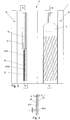
- the workstation 10 includes an example in the Figures 2 . 3 . 5 , and 7 closer to printing station 21, at which the cylindrical objects 6 during rotation about respective axes of rotation 5 using printheads 22, 23, as shown in the Figures 3 . 5 and 7 are shown in more detail, are printed in a predetermined range.
- the work station 14 is embodied as an inspection device by way of example and makes it possible to determine a print quality of the print image applied by the printing station 21 to the peripheral surface of the object 6.
- the further workstations 11 to 13 and 15 to 17 are used for further processing of the cylindrical objects 6, for example for applying a protective lacquer to the printing or for mounting components to the objects 6.
- At the workstation 18 takes place an unloading process in which the cylindrical objects 6 by means of a transport device 20 of the mandrel-like workpiece holders 4 are deducted and fed to a non-illustrated further transport system.
- the workpiece turntable 4 leads to the stepwise processing of the cylindrical objects 6 at the respective workstations 8 to 18 a rotary step movement by the angle W, in which the paired workpiece holders 4 from one of the respective workstation 8 to 18 opposite position in one of the subsequent workstation 8 to 18 opposite position are transported, wherein the rotational step movement is carried out as a sequence of acceleration from standstill, a deceleration of the achieved target speed and a subsequent downtime.
- a non-illustrated drive for the workpiece rotary table 3 is designed such that the acceleration and deceleration of the workpiece rotary table 3 are completely freely adjustable over a wide range and downtime and adapted to the requirements of processing the respective cylindrical objects 6 at the workstations 8 to 18 can be.
- the drive of the workpiece rotary table 3 can be controlled such that the workpiece holders 4 in an intermediate step, which can be used for cleaning or other maintenance of workstations 8 to 18, by a rotational step movement with the step size W / 2 between the workstations 8 to 18 come to rest, as shown schematically in the FIG. 1a is shown. This is important, for example, for carrying out a cleaning of the printing station 21.
- the in the Figures 2 and 3 illustrated printing station 21 includes two mirror images of each other arranged pressure means 24, 25 for the sake of clarity in the FIG. 3 only one in two with the Print station 21 printable cylindrical objects 6 shown, in contrast, are in the FIG. 2 both arranged opposite to the printing station 21 and rotatably mounted cylindrical objects 6 shown.
- Each printing device 24, 25 comprises by way of example in each case two printing heads 22, 23, each of which has a strip-like shape and on whose cylindrical object 6 facing end face 26, 27 an exemplary nozzle row 28, 29 is formed.
- Each of the rows of nozzles 28, 29 comprises several, preferably in the same pitch or spacing along an extension axis 30, exemplified as nozzles 31 formed Farbdosieriana.
- Each of the nozzles 31 in the nozzle rows 28, 29, as shown in the FIGS. 4 . 6 and 8th are shown in section, is exemplarily individually controlled and formed in the illustrated embodiment for dispensing drops of ink.
- the two print heads 22, 23 are designed to deliver a first color, in particular the color cyan.
- further printing stations 32, 33 for dispensing a second or third color, in particular the color magenta and the color yellow (yellow) are formed.
- a printed image can be produced by a combination of differently colored ink drops which are dispensed onto the object 6 at the respective printing stations 21, 32, 33.
- more than three printing stations are provided in order to apply a larger number of colors, especially white as at least partially applied primer for the printing and / or a transparent topcoat for the carried out printing on the article 6.
- the respective printheads for dispensing a plurality of colors in particular the colors cyan, magenta and yellow, formed so that a printing of an object can be done in a single printing operation.
- a resolution of a printed image that is to say a minimum distance between the center points of adjacently arranged ink droplets in different spatial directions, can be influenced in different ways.
- each nozzle 31 of each print head 22, 23 can be driven at a predetermined frequency and can deliver drops of ink onto the peripheral surface of the object 6 at the predetermined frequency.
- the frequency determines the resolution in the circumferential direction. At a low rotational speed results in a high resolution in the circumferential direction, at high rotational speed results in a low resolution in the circumferential direction.
- a resolution for the printed image in a spatial direction parallel to the axis of rotation 5 is determined based on a print head 22 or 23 exclusively by the pitch of the nozzles 31 along the extension axis 30 of the respective print head 22, 23, as long as during the execution of the printing process no translational displacement of the respective Printhead 22, 23 along the axis of rotation 5 takes place. In this case, an annular application of the ink drops takes place on the peripheral surface of the article 6.
- the respective printing device 24, 25 is set in a suitable manner.
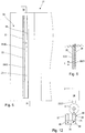
- the two printing heads 22, 23 of the respective printing device 24, 25 each associated with an electric drive 34, 35, which is electrically connected to a control device 36, respectively.
- the drive 34, 35 is an example of an electric motor, the drive shaft, not shown, with a rotatable and stationary in the as a print head carrier Serving pressure device 24, 25 mounted threaded spindle 37, 38 is connected.
- non-visible lock nut which is designed to implement a rotational movement of the threaded spindle 37, 38 in a translational movement of the respective print head 22, 23.
- 25 sliding guide surfaces 39, 40, 41, and 42 are provided, which enable a slide-movable and rotationally fixed mounting of the print heads 22, 23 on the printing device 24, 25.
- the control device 36 is designed for an independent control of the electrical drives 34, 35, so that the translational position of the print heads 22, 23 along the extension axis 30 can be adjusted freely.
- the print heads 22, 23 for generating a helical print track is indicated by the parallel and equidistant lines on the object 6, positioned by means of adjusting means serving as drives 34, 35 to each other such that the in the FIG. 4 shown nozzles 31 of the adjacent print heads 22, 23 are each on the parallel and mutually equidistant lines.
- Such an adjustment and synchronized use of the printheads 22, 23 can achieve a doubling of the resolution for the print image over a use of only one printhead 22 or 23 in a helical printing operation.
- the spacing of the lines depends on the desired resolution, the number of revolutions of the object 6 during the printing process with respect to the printheads 22, 23 and the diameter of the object 6.
- the print heads 22, 23 can be arranged offset by half the pitch t to each other and remain stationary during the simple rotation of the article 6.
- a further increase in the resolution can be achieved if the object 6 opposite to the two printheads 22, 23 performs several revolutions and the printheads 22, 23 during the rotational movement of the article 6 for performing the printing operation synchronously shifted along the extension axis 30, as a result a helical shape for a trace of pressure points, which are discharged from a nozzle 31 on the peripheral surface of the article 6, is achieved, in which the successively generated pressure traces of the individual nozzles are applied to the object 6 far less than a pitch t apart.
- the synchronous displacement of the printheads 22, 23 during the printing operation is selected so that a slope of the track of printing dots during one revolution of the object corresponds to a value obtained by dividing the pitch t of the nozzles 31 of a printhead 22 or 23 along the axis of extent 30 corresponds to an integer value.
- the two print heads 22, 23 with the respective drives 34, 35 are exemplarily set such that they along the track of Pressure points are arranged offset to one another such that they lie on mutually parallel and equidistant lines and that this position of the print heads 22, 23 is also maintained during the execution of the printing operation.
- the two print heads 22, 23 during the execution of a printing operation not only be moved synchronously to the extension axis but also be moved relative to each other.
- it may be provided to print the peripheral surface of the article 6 with different resolutions.
- both the relative position of the print heads 22, 23 along the extension axis 30 and a change in the rotational speed of the object 6 and / or a drive frequency for the control of the print heads 22, 23 may be provided.
- an increase in resolution for the print image in the circumferential direction can be achieved by reducing the rotation speed for the object 6 while maintaining the drive frequency for driving the print heads 22, 23 and / or the drive frequency for driving the print heads 22, 23 is increased.
- the printing device 24, 25 connected to the control device 36 is adjusted in response to the detection of printing errors in the generated print image by the inspection system in the workstation 14 for compensation of these printing errors at the next article to be printed .
- the two print heads 22, 23 are positioned relative to one another in such a way that a nozzle 31 of one of the print heads 22, 23 can be used to deliver a clogged nozzle 31 of the other print head 22, 23.
- the intact nozzle 31 does not necessarily have to be arranged on the same track of pressure points, in particular a helical path, like the defective nozzle 31, even a slight offset which is smaller than the pitch t may possibly be acceptable.
- FIGS. 4 and 5 is shown as a printing of a high-resolution object 6 in the direction of the extension axis 30 is made, whose extent along the extension axis 30 is greater than a corresponding extent of the print heads 22, 23.
- the printing process begins by way of example with a positioning of the two print heads 22, 23 in a lower starting position according to FIG FIG. 3 in which the print heads 22, 23 are arranged in accordance with the slope of the intended spiral pressure taking into account the desired resolution. Starting from this positioning, the print heads 22, 23 are moved synchronously to one another during the execution of the printing process along the extension axis 30 and the object 6 is rotated about the rotation axis 5 until the entire peripheral surface of the object 6 has been moved past the print heads 22, 23 and with Color could be provided.
- a helical printing of the peripheral surface of the article 6 is provided with a resolution along the extension axis 30, which is greater than the pitch t of the nozzles 31 to the printheads 22, 23.
- a multiple rotation of the article 6 with respect to the print heads 22, 23 is provided, during which the print heads 22, 23 are moved synchronously with each other along the extension axis 30 to produce the desired helical shape for the print tracks.
- the last nozzle 31 of the printhead 22 arranged as an example below would be arranged at the pitch t with respect to the first nozzle 31 of the printhead 23 arranged by way of example above, this would result in an offset of the print tracks of the adjacent print heads relative to the desired pitch for the helical printing of the object 6 22, 23 by the amount ds.
- the two Printheads 22, 23 are shifted by a resolution-dependent and diameter-dependent amount relative to each other, so that the amount ds disappears.
- seamless printing of the peripheral surface of the article 6 can be realized.
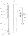
- a functional module 43 is arranged opposite the respective printing device 24, 25.
- the functional module 43 comprises a cleaning station 44 and a drying station 45, which by way of example on a common, rotatable about a perpendicular to the plane of the FIGS. 9 and 10 aligned rotational axis 46 mounted pivot receptacle 47 are mounted.
- the cleaning station 44 is equipped with an absorbent material, not shown, which can receive a large amount of dye, in particular ink, discharged from the print heads 22, 23 during the execution of a cleaning cycle.
- the workpiece rotary table 3 is controlled such that the respective workpiece holders 4 in the in the FIG. 1a illustrated intermediate position between two workstations 9 to 17 are arranged so that no interfering objects between the print heads 22, 23 and the respective cleaning station 44 are arranged.
- the pivot receptacle 47 is pivoted about the pivot axis 46, so that the cleaning station 44 is removed from the print head 22 or 23 and the drying station 45 reaches the print head 22 or 23 opposite position.
- the drying station 44 is at the drying station 44 to an array of light sources not shown, in particular light-emitting diodes. These light sources are designed to emit light of a predeterminable intensity and wavelength, these properties being adapted to the properties of the ink or ink to be hardened, which are dispensed from the respective print heads 22, 23 onto the object.
- a further workstation in particular the workstation 15, is equipped with a further printing station 48, which is responsible for applying a closed or selective, in particular transparent, topcoat to the peripheral surface of the object 6, in particular to the printing stations 21 , 32 and 33 printed areas, are formed and which has the same structure as one of these printing stations 21, 32, 33.
- the in the FIG. 11 illustrated printing station 50 is provided for a multi-color printing of the article 6 in a printing operation and has for this purpose three printheads 51, 52 and 53, each having three nozzle strips 54, 55 and 56. Each of the three nozzle strips 54, 55 and 56 is provided for the discharge of a color, in particular from the group cyan, magenta and yellow.
- Each of the print heads 51, 52, and 53 can be positioned in the same way along the extension axis 30 by means of an associated drive 57, 58, 59 and a respective associated threaded spindle 60, 61, 62, as for the printing stations 21, 32, 33 the case is.
- the arrangement of printing heads 51, 52, and 53 of the printing station 50 by means of a drive 63, which comprises a transmission device, not shown, relative to the axis of rotation 5 of the workpiece holder 4 can be tilted.
- the tilting direction is selected such that a distance from the print heads 51, 52 and 53 relative to the object 6 remains at least substantially constant.
- a drive 64 is provided with a gear device not shown in detail, which allows a displacement of the print heads in the radial direction to keep a controlled or regulated adjustment of a radial distance between the print heads 51, 52 and 53 and the object 6 at least largely constant.
- the drives 63 and 64 can be provided in the same way also at the printing stations 21, 32 and 33, if there is a controlled or controlled adaptation to different geometries of objects 6 is required.
- the cleaning station 66 together with the drying station 67 is accommodated on a movably mounted carriage 68.
- the cleaning station 66 has a receptacle, not shown, which is provided at an upper, the printheads 22, 23 facing edge region with a circumferential elastic sealing means 69.
- the carriage 68 is designed for carrying out two mutually perpendicular translational movements 70, 71 and for this purpose with drive means, not shown, for example, electric or pneumatic drives equipped.
- the translational movement 70 which is preferably carried out transversely to the axis of rotation 2 of the workpiece turntable 3, serves to selectively clean the cleaning station 66 or the drying station 67 below and opposite to the printheads 22, 23 to be arranged.
- the translational movement 71 which is preferably carried out parallel to the rotation axis 2 of the workpiece turntable 3, serves to bring the cleaning station 66 into sealing contact with the print heads 22, 23. This allows the desired cleaning cycle to be carried out.
- the workpiece rotary table 3 is controlled such that the respective workpiece holders 4 in the in FIG. 1a represented intermediate position between two work stations 9 to 17 are arranged so that no interfering objects between the Druccköpfen 22, 23 and the respective cleaning station 66 are arranged.
- the cleaning station 66 is removed from the printheads by means of the translatory movements 70 and 71 such that the drying station 67 reaches a position opposite the printhead 22, 23 and activates ink applied by the printheads 22, 23 to the object 6 , hardened or dried.
- a translational movement of the object to be printed in particular provided parallel to its axis of rotation.
- a rotation of the print heads around the stationary or translationally moving object is provided around.
Description
Die Erfindung betrifft eine Druckmaschine mit einer Druckeinrichtung zur Bedruckung einer Umfangsoberfläche eines Gegenstands, mit wenigstens zwei Druckköpfen, die jeweils wenigstens eine Reihenanordnung von Farbdosierelementen, insbesondere Farbdüsen, aufweisen, die jeweils für eine individuelle vorgebbare Abgabe von Farbe auf den Gegenstand ausgebildet sind. Ferner betrifft die Erfindung ein Verfahren zum Betreiben einer Druckmaschine mit einer Druckeinrichtung.The invention relates to a printing machine with a printing device for printing on a peripheral surface of an object, with at least two printheads, each having at least one row of Farbdosierelementen, especially ink nozzles, each of which is designed for an individual predefinable release of color to the object. Furthermore, the invention relates to a method for operating a printing press with a printing device.
Aus der
Die
Die
Aus der
Die
Die Aufgabe der Erfindung besteht darin, eine Druckmaschine sowie ein Verfahren zum Betreiben einer Druckmaschine mit einer Druckeinrichtung bereitzustellen, mit denen eine besonders effiziente Bedruckung eines Gegenstands mit hoher Auflösung ermöglicht wird.The object of the invention is to provide a printing machine and a method for operating a printing press with a printing device, with which a particularly efficient printing of a high-resolution object is made possible.
Diese Aufgabe wird gemäß einem ersten Aspekt der Erfindung für eine Druckeinrichtung der eingangs genannten Art mit den Merkmalen des Anspruchs 1 gelöst. Hierbei ist vorgesehen, dass die Druckeinrichtung der Druckmaschine zur Durchführung des Verfahrens nach einem der Ansprüche 11 bis 13 ausgebildet ist.This object is achieved according to a first aspect of the invention for a printing device of the type mentioned with the features of claim 1. It is provided that the printing device of the printing press for carrying out the method according to one of claims 11 to 13 is formed.
Dabei wird davon ausgegangen, dass der Druckkopf mehrere längs einer Erstreckungsachse angeordnete Farbdosierelemente aufweist, wobei jedes der Farbdosierelemente für eine individuelle Abgabe von Farbpartikeln oder Farbtropfen, insbesondere Tintentropfen, ausgebildet ist. Vorzugsweise sind die Farbdosierelemente mit konstanter Teilung längs der Erstreckungsachse angeordnet, so dass jeweils benachbarte Farbdosierelemente einen konstanten Abstand zueinander aufweisen. Die längs der Erstreckungsachse angeordneten Farbdosierelemente bilden eine Druckzeile, wobei ein Druckkopf mit einer oder alternativ mit mehreren Druckzeilen ausgestattet sein kann, wobei mehrere Druckzeilen vorzugsweise parallel und mit jeweils gleichem Abstand zueinander angeordnet sind. Mit Hilfe der elektrisch ansteuerbaren Einstelleinrichtung, bei der es sich beispielsweise um einen elektrischen Lineardirektantrieb, einen elektrischen Spindelantrieb oder einen Riemen- oder Seilzugantrieb handeln kann, wird eine Relativbewegung eines ersten Druckkopfs gegenüber einem zweiten Druckkopf ermöglicht. Durch diese Relativbewegung kann darauf Einfluss genommen werden, welche Position die Farbdosierelemente des ersten Druckkopfs längs der Erstreckungsachse relativ zu den Farbdosierelementen des zweiten Druckkopf einnehmen. Beispielsweise kann vorgesehen sein, dass die Farbdosierelemente des ersten Druckkopfes bezüglich der Erstreckungsachse um einen Betrag gegenüber den Farbdosierelementen des zweiten Druckkopfes versetzt sind, der 50 Prozent der Teilung der Farbdosierelemente entspricht. Dadurch dann bei geeigneter Ansteuerung der beiden Druckköpfe auf der Umfangsoberfläche des zu bedruckenden Gegenstands einen Druckbild erzeugt werden, dessen Auflösung längs der Erstreckungsachse doppelt so groß ist wie die Teilung für die Farbdosierelemente der beiden Druckköpfe längs der Erstreckungsachse.In this case, it is assumed that the print head has a plurality of ink dosing elements arranged along an extension axis, wherein each of the ink dosing elements is designed for individual dispensing of color particles or drops of ink, in particular ink droplets. Preferably, the Farbdosierelemente are arranged at a constant pitch along the extension axis, so that each adjacent Farbdosierelemente have a constant distance from each other. The along the extension axis arranged Farbdosierelemente form a print line, wherein a print head can be equipped with one or alternatively with multiple print lines, wherein a plurality of print lines are preferably arranged parallel to each other and with the same distance. With the help of electrically controllable adjustment, in the it may be, for example, an electric linear linear drive, an electric spindle drive or a belt or cable drive, a relative movement of a first print head relative to a second print head is made possible. This relative movement can influence which position the ink metering elements of the first print head occupy along the extension axis relative to the ink metering elements of the second print head. For example, it may be provided that the Farbdosierelemente the first print head are offset with respect to the extension axis by an amount relative to the Farbdosierelementen the second print head, which corresponds to 50 percent of the pitch of the Farbdosierelemente. As a result, with appropriate control of the two print heads on the peripheral surface of the object to be printed, a printed image are generated whose resolution along the extension axis is twice as large as the pitch for the Farbdosierelemente the two printheads along the extension axis.
Ferner kann durch die Veränderung der relativen Lage des ersten Druckkopfs gegenüber dem zweiten Druckkopf eine Anpassung der Lage der Farbdosierelemente an Druckspuren erzielt werden, die aufgrund unterschiedlicher Anforderungen an die Auflösung des zu erzeugenden Druckbilds und/oder aufgrund unterschiedlicher Durchmesser der zu bedruckenden Gegenstände unterschiedliche Steigungen aufweisen. Bei Aufbringung einer wendelförmigen Druckspur auf den Gegenstand muss in Abhängigkeit von der gewünschten Auflösung für das zu erzeugende Druckbild und in Abhängigkeit vom Durchmesser des Gegenstands eine Anpassung der Steigung für die wendelförmige Druckspur erreicht werden, was durch die Einstellung der relativen Lage der Druckköpfe durch Relativbewegung längs der Erstreckungsachs zueinander gewährleistet werden kann.Furthermore, by changing the relative position of the first print head relative to the second print head, an adjustment of the position of the ink metering elements to print tracks can be achieved which have different slopes due to different requirements for the resolution of the print image to be generated and / or due to different diameters of the articles to be printed , When a helical print track is applied to the object, an adjustment of the pitch for the helical print track must be achieved, depending on the desired resolution for the print image to be generated and depending on the diameter of the article, which is achieved by adjusting the relative position of the print heads by relative movement the extension axis can be guaranteed to each other.
Durch die elektrisch ansteuerbare Einstelleinrichtung kann ergänzend oder alternativ auch eine Veränderung der Auflösung des Druckbilds längs der Erstreckungsachse auch während der Durchführung eines Druckvorgangs vorgesehen werden, was beispielsweise von Interesse ist, wenn Teilbereiche des Druckbilds mit höherer Auflösung als sonstige Bereiche des Druckbilds erzeugt werden sollen. Für die Durchführung des Druckvorgangs ist vorgesehen, dass der zu bedruckende Gegenstand gegenüber der Druckeinrichtung eine Relativbewegung durchführt, die zumindest im Wesentlichen, insbesondere exakt, quer zu Erstreckungsachse der Farbdosierelemente ausgerichtet ist. Bei dieser Relativbewegung des Gegenstands gegenüber der Druckeinrichtung kann es sich insbesondere um eine reine Translationsbewegung, um eine reine Rotationsbewegung oder um eine Überlagerung einer Translationsbewegung und einer Rotationsbewegung handeln. Vorzugsweise ist eine wendelförmige Bedruckung des Gegenstands vorgesehen, die wahlweise durch eine, insbesondere synchrone, Translationsbewegung der Druccköpfe längs der Erstreckungsachse bei ausschließlicher Rotation des Gegenstands oder durch eine überlagerte Rotations- und Translationsbewegung des Gegenstands gegenüber den ruhenden Druckköpfen oder durch eine Kombination einer überlagerten Rotations- und Translationsbewegung des Gegenstands mit einer, insbesondere synchronen, Translationsbewegung der Druckköpfe längs der Erstreckungsachse durchgeführt werden kann. Dabei kann vorgesehen werden, dass die relative Lage der Druckköpfe längs der Erstreckungsachse zueinander in Abhängigkeit von der zu erzielenden Auflösung und/oder des Durchmessers des Gegenstands vor der Durchführung des Druckvorgangs eingestellt und während der Durchführung des Druckvorgangs beibehalten wird.By means of the electrically controllable adjusting device, a change in the resolution of the printed image along the extension axis can also be provided during the execution of a printing operation, which is of interest, for example, if partial regions of the printed image are to be produced with higher resolution than other regions of the printed image. For carrying out the printing operation, it is provided that the object to be printed relative to the printing device performs a relative movement, which is aligned at least substantially, in particular exactly, transversely to the extension axis of the Farbdosierelemente. This relative movement of the object relative to the printing device may in particular be a pure translational movement, a pure rotational movement or an overlay of a translational movement and a rotational movement. Preferably, a helical printing of the article is provided, which is optionally by a, in particular synchronous, translational movement of the printing heads along the axis of extension in exclusive rotation of the article or by a superimposed rotational and translational movement of the article relative to the stationary printheads or by a combination of a superimposed rotary and translational movement of the article with a, in particular synchronous, translational movement of the print heads along the extension axis can be performed. It can be provided that the relative position of the print heads along the extension axis to each other depending on the achievable resolution and / or the diameter of the article before the implementation of the printing process is set and maintained during the execution of the printing operation.
Vorteilhafte Weiterbildungen der Erfindung sind Gegenstand der Unteransprüche.Advantageous developments of the invention are the subject of the dependent claims.
Zweckmäßig ist es, wenn der wenigstens eine weitere Drucckopf, insbesondere alle weiteren Druckköpfe, mit einer elektrisch ansteuerbaren Einstelleinrichtung verbunden und beweglich längs der Erstreckungsachse der Farbdosierelemente am Druckkopfträger angeordnet ist. Hierdurch kann jeder der Druckköpfe, insbesondere auch während der Durchführung eines Druckvorgangs für einen Gegenstand, hinsichtlich seiner Positionierung längs der Erstreckungsachse der Farbdosierelemente eingestellt werden. Weist das zu erzeugende Druckbild auf der Umfangsfläche des zu bedruckenden Gegenstands beispielsweise einen Druckbereich mit geringer Ausdehnung und hoher Bildauflösung längs der Erstreckungsachse und umgebende Druckbereiche mit größerer Ausdehnung und geringerer Bildauflösung längs der Erstreckungsachse auf, so kann vorgesehen werden, dass die Druckköpfe zur Erzeugung des Druckbereichs mit hoher Auflösung eine relative Positionierung zueinander einnehmen, die sich von einer relativen Positionierung der Druckköpfe zur Erzeugung der Druckbereiche mit niedriger Auflösung unterscheidet.It is expedient if the at least one further print head, in particular all other print heads, is connected to an electrically controllable setting device and arranged movably along the extension axis of the ink metering elements on the print head carrier. In this way, each of the print heads, in particular also during the execution of a printing operation for an object, can be adjusted with regard to its positioning along the extension axis of the ink metering elements. If the image to be printed on the peripheral surface of the object to be printed has, for example, a print area with low expansion and high image resolution along the extension axis and surrounding print areas with greater expansion and lower image resolution along the extension axis, then it can be provided that the print heads are used to generate the print area high resolution relative position to each other, which differs from a relative positioning of the printheads to produce the low-resolution printing areas.
Bei einer vorteilhaften Weiterbildung der Erfindung ist vorgesehen, dadurch gekennzeichnet, dass die Druckköpfe parallel zueinander ausgerichtet sind und quer zu Erstreckungsachse der Farbdosierelemente unmittelbar benachbart, insbesondere gleitbeweglich aneinandergrenzend, angeordnet sind. Hierdurch lässt sich eine kompakte Anordnung der Druckköpfe erreichen, was insbesondere bei einer Bedruckung von zumindest im Wesentlichen rotationssymmetrischen, insbesondere kreiszylindrischen Gegenständen wie beispielsweise Aerosoldosenrohlingen, vorteilhaft ist, da ansonsten je nach Dimensionierung der zu bedruckenden Gegenstände eine Einhaltung einer Abstandsvorgabe zwischen den Druckköpfen und dem Gegenstand schwierig wäre. Vorzugsweise sind die aneinander gereihten Farbdosierelemente der benachbarten Druckköpfe jeweils parallel zueinander ausgerichtet und quer zur Erstreckungsachse, insbesondere bezogen auf eine Umfangsrichtung des zu bedruckenden Gegenstands, in einem festen Abstand zueinander angeordnet. Gegebenenfalls kann auch vorgesehen werden, einen Abstand der Druckköpfe quer zur Erstreckungsachse durch geeignete Einstellmittel einstellbar zu machen. Ergänzend oder alternativ kann vorgesehen werden, wenigstens einen Druckkopf drehbar gelagert um eine Schwenkachse anzuordnen, wobei die Schwenkachse vorzugsweise parallel zur Erstreckungsachse ausgerichtet ist, so dass eine Auftreffrichtung für die vom Druckkopf abgegebenen Farbpartikel, insbesondere Tintentropfen, auf die Außenoberfläche des Gegenstands eingestellt werden kann. Dies ist insbesondere dann von Interesse, wenn mit der gleichen Druckeinrichtung Gegenstände mit stark unterschiedlichen Durchmessern bedruckt werden sollen.In an advantageous embodiment of the invention is provided, characterized in that the print heads are aligned parallel to each other and transverse to the extension axis of the Farbdosierelemente immediately adjacent, in particular slidably adjacent to each other, are arranged. This makes it possible to achieve a compact arrangement of the print heads, which is advantageous, in particular, when printing on at least substantially rotationally symmetrical, in particular circular cylindrical objects such as aerosol can blanks, since otherwise, depending on the dimensioning of the objects to be printed, compliance with a distance specification between the print heads and the object difficult. Preferably, the juxtaposed Farbdosierelemente the adjacent printheads are each parallel aligned with each other and arranged transversely to the extension axis, in particular with respect to a circumferential direction of the object to be printed, at a fixed distance from each other. Optionally, it may also be provided to make a spacing of the print heads transversely to the extension axis adjustable by suitable adjustment means. Additionally or alternatively, it may be provided to arrange at least one print head rotatably mounted about a pivot axis, wherein the pivot axis is preferably aligned parallel to the extension axis, so that an incident direction for the color particles emitted by the print head, in particular ink drops, can be adjusted to the outer surface of the object. This is of particular interest when articles with very different diameters are to be printed with the same printing device.
In weiterer Ausgestaltung der Erfindung ist vorgesehen, dass die Druckköpfe mittels der wenigstens einen Einstelleinrichtung zwischen einer ersten Funktionsstellung, in der die Farbdosierelemente benachbarter Druckköpfe quer zu Erstreckungsachse überlappungsfrei angeordnet sind, und einer zweiten Funktionsstellung, in der eine Überlappung von Farbdosierelementen benachbarter Druckköpfe quer zu Erstreckungsachse vorliegt, einstellbar sind. Hierdurch kann eine vorteilhafte Anpassung der Auflösung der Druckeinrichtung bezüglich der Erstreckungsachse an den jeweiligen Bedarf vorgenommen werden. Bei der ersten Funktionsstellung ist vorgesehen, dass die Farbdosierelemente benachbarter, insbesondere sämtlicher, Druckköpfe auf zueinander parallelen Linien liegen, wobei die parallelen Linien quer zu Erstreckungsachse ausgerichtet sind und ein Abstand der parallelen Linien jeweils der Teilung der Farbdosierelemente entspricht. Dabei ist vorzugsweise vorgesehen, dass auf keiner der parallelen Linien zwei Farbdosierelemente benachbarter Druckköpfe angeordnet sind. Bei dieser Einstellung entspricht die zu erzielende Auflösung längs der Erstreckungsachse zumindest für den Fall, dass jeder Oberflächenbereich des zu bedruckenden Gegenstands von den Druckköpfen nur einmalig überstrichen wird, exakt der Teilung der Farbdosierelemente und es kann eine maximale Drucklänge bedruckt werden. Demgegenüber ist bei der zweiten Funktionsstellung vorgesehen, dass eine zumindest teilweise Überlappung benachbarter Druckköpfe bezüglich der Erstreckungsachse vorliegt, wodurch im Überlappungsbereich eine höhere Auflösung für das zu erzeugende Druckbild gewährleistet werden kann, als dies durch die Teilung benachbarter Farbdosierelemente bezogen auf die Erstreckungsachse vorgegeben ist. Dabei liegt zumindest ein Teil der Farbdosierelemente des ersten Druckkopfs auf den gleichen parallelen Linien wie zumindest ein Teil der Farbdosierelemente des zweiten Druckkopfs. Hiermit kann beispielsweise im Überlappungsbereich der benachbarten Druckköpfe eine höhere Druckauflösung längs der Erstreckungsachse erzielt werden als und den Bereichen ohne Überlappung. Dies gilt insbesondere für den Fall, dass jeder Oberflächenbereich des zu bedruckenden Gegenstands von den Druckköpfen nur einmalig überstrichen wird.In a further embodiment of the invention it is provided that the printheads by means of at least one adjustment between a first functional position in which the Farbdosierelemente adjacent printheads are arranged transversely to extension axis overlapping, and a second functional position in which an overlap of Farbdosierelementen adjacent printheads transversely to extension axis present, are adjustable. In this way, an advantageous adaptation of the resolution of the printing device with respect to the extension axis to the respective need can be made. In the first functional position is provided that the Farbdosierelemente adjacent, in particular all, printheads lie on mutually parallel lines, the parallel lines are aligned transversely to the extension axis and a distance of the parallel lines respectively corresponds to the pitch of the Farbdosierelemente. It is preferably provided that on each of the parallel lines two Farbdosierelemente adjacent printheads are arranged. At this Adjustment corresponds to the resolution to be achieved along the extension axis, at least in the event that each surface region of the object to be printed is passed over only once by the print heads, exactly the pitch of the ink metering elements and a maximum print length can be printed. In contrast, it is provided in the second functional position that there is an at least partial overlap of neighboring print heads with respect to the extension axis, whereby a higher resolution for the print image to be generated can be ensured in the overlap area, as is predetermined by the division of adjacent Farbdosierelemente with respect to the extension axis. At least part of the ink metering elements of the first print head lie on the same parallel lines as at least part of the ink metering elements of the second print head. Hereby, for example, in the overlapping area of the adjacent print heads, a higher print resolution along the extension axis can be achieved than and the areas without overlap. This is especially true in the event that each surface area of the object to be printed is only passed over once by the printheads.
Bevorzugt umfasst wenigstens ein Druckkopf wenigstens zwei parallel zur Erstreckungsachse ausgerichtete, insbesondere als Tintendüsen, ausgebildete Reihen von Farbdosierelementen. Vorzugsweise weisen die wenigstens zwei Reihen von Farbdosierelementen längs der Erstreckungsachse jeweils die gleiche Teilung für die Farbdosierelemente auf. Gegebenenfalls sind die Farbdosierelemente benachbarter Reihen bezogen auf die Erstreckungsachse um einen vorgebbaren Betrag, insbesondere um einen Bruchteil der jeweiligen Teilung versetzt zueinander angeordnet. Insbesondere kann vorgesehen sein, dass benachbarte Reihen von Farbdosierelementen zu Abgabe unterschiedliche Farben, insbesondere Cyan, Magenta und Gelb (Yellow) vorgesehen sind. Hierdurch kann der jeweilige Druckkopf während eines Druckvorgangs den gesamten zugeordneten Bildausschnitt des Druckbilds erzeugen, wobei je nach angewandtem Druckverfahren, insbesondere bei Anwendung des Tintenstrahldruckerverfahrens, ein vorhersehbare Vermischung der Farben, die von den unterschiedlichen Farbdosierelementen abgegeben werden, eintritt.Preferably, at least one print head comprises at least two rows of color metering elements aligned parallel to the extension axis, in particular as ink nozzles. Preferably, the at least two rows of Farbdosierelementen along the extension axis each have the same pitch for the Farbdosierelemente. Optionally, the Farbdosierelemente adjacent rows relative to the extension axis by a predetermined amount, in particular by a fraction of the respective pitch offset from each other. In particular, it can be provided that adjacent rows of Farbdosierelementen for dispensing different colors, especially cyan, magenta and yellow (yellow) provided are. In this way, the respective print head can generate the entire associated image section of the print image during a printing process, whereby depending on the printing method used, in particular when using the inkjet printer process, predictable mixing of the colors emitted by the different ink dosing elements occurs.
Vorteilhaft ist es, wenn die Farbdosierelemente längs der Erstreckungsachse in einer vorgebbaren Teilung angeordnet sind und dass die Einstelleinrichtung für eine Positionierung des Druckkopfes mit einer Positioniergenauigkeit ausgebildet ist, die kleiner, vorzugsweise kleiner 50 Prozent, bevorzugt kleiner 25 Prozent, besonders bevorzugt kleiner 10 Prozent, insbesondere kleiner zwei Prozent, der Teilung der Farbdosierelemente längs der Erstreckungsachse ist. Mit einer derartigen Positioniergenauigkeit für die Einstelleinrichtung kann der jeweilige Druckkopf in reproduzierbarer Weise relativ zu benachbarten Druckköpfen angeordnet werden, um beispielsweise während der Durchführung eines Druckvorgangs unterschiedliche Auflösungen und unterschiedliche Druckgeschwindigkeiten für die Bedruckung des Gegenstands zu ermöglichen. Exemplarisch ist vorgesehen, dass die Einstelleinrichtung eine Positioniergenauigkeit weniger als 5 Mikrometer aufweist und dass eine Teilung der Farbdosierelemente in einem Bereich von 0,25 Millimeter liegt.It is advantageous if the Farbdosierelemente along the extension axis are arranged in a predetermined pitch and that the adjustment is designed for positioning of the print head with a positioning accuracy, the smaller, preferably less than 50 percent, preferably less than 25 percent, more preferably less than 10 percent, in particular less than two percent, the pitch of the Farbdosierelemente along the extension axis. With such positioning accuracy for the adjustment means, the respective printhead can be arranged in a reproducible manner relative to adjacent printheads, for example, to allow for different resolutions and different printing speeds for the printing of the article during the execution of a printing operation. By way of example, it is provided that the setting device has a positioning accuracy of less than 5 micrometers and that a pitch of the ink metering elements is in a range of 0.25 millimeters.
Zweckmäßig ist es, wenn dem Druckkopfträger wenigstens zwei zueinander relativbeweglich gelagerte Gruppen von Druckköpfen zugeordnet sind, wobei jede Gruppe von Druckköpfen wenigstens einen, insbesondere zwei Druckköpfe umfasst. Mithilfe der wenigstens zwei Gruppen von Druckköpfen kann die Umfangsoberfläche eines Gegenstands wahlweise im Rahmen einer einzigen Drehung oder gegebenenfalls nur einer teilweisen Drehung mit hoher Auflösung in Umfangsrichtung und/oder längs der Erstreckungsachse bedruckt werden, wobei hierzu die beiden Gruppen von Druckköpfen zumindest teilweise zueinander überlappend angeordnet werden. Alternativ kann vorgesehen sein, die Umfangsoberfläche des Gegenstands im Rahmen mehrerer Umdrehungen zu bedrucken, wobei hierzu keine oder nur eine geringe Überlappung der Gruppen von Druckköpfen zueinander vorgesehen wird und die Druckköpfe der benachbarten Gruppen von Druccköpfen in Abhängigkeit von der gewünschten Steigung der Druckspur zueinander eingestellt werden. Vorzugseise wird davon ausgegangen, dass die jeweiligen Gruppen von Druckköpfen jeweils zur Abgabe einer einzigen Farbe ausgebildet sind.It is expedient if at least two mutually relatively movably mounted groups of print heads are assigned to the print head carrier, wherein each group of print heads comprises at least one, in particular two, print heads. With the aid of the at least two groups of printheads, the peripheral surface of an article may optionally be subjected to a single rotation or possibly only a partial rotation high resolution in the circumferential direction and / or printed along the extension axis, for which purpose the two groups of print heads are arranged at least partially overlapping each other. Alternatively, it may be provided to print the peripheral surface of the object in the course of several revolutions, with no or only a slight overlap of the groups of printheads being provided for each other and the printheads of the adjacent groups of printing heads being adjusted to one another depending on the desired pitch of the printing track , It is preferred that the respective groups of printheads are each designed to dispense a single color.
Vorteilhaft ist es, wenn dem Druckkopfträger eine den Druccköpfen gegenüberliegend angeordnete Trocknungsstation zugeordnet ist, um im Anschluss an den Farbauftrag eine Trocknung der aufgebrachten Farbe zu ermöglichen. Mit Hilfe der Trocknungsstation wird ein Aushärtungsvorgang für die von den Farbdosierelementen auf die Oberfläche des zu bedruckenden Gegenstands abgegebenen Farbpartikel oder Farbtropfen durchgeführt. Hierbei ist vorzugsweise eine kontaktlose Energieeinkopplung, beispielsweise durch Infrarotlicht oder Ultraviolettlicht, auf den Gegenstand vorgesehen. Ein derartiger Trocknungs- oder Aushärtevorgang ist besonders vorteilhaft, wenn es sich bei den Gegenstand um einen zumindest im wesentlichen rotationssymmetrischen Gegenstand handelt, der während des Druckvorgangs um eine Rotationsachse rotiert wird, die zumindest im Wesentlichen parallel zu den Erstreckungsachse der Druckköpfe ausgerichtet ist. In diesem Fall passiert der zu bedruckenden Oberflächenbereich des Gegenstands zunächst den oder die Druckköpfe, um im weiteren Zuge seiner Rotation auch die Trocknungsstation zu passieren, so dass im Idealfall innerhalb ungefähr einer Rotationsbewegung von ca. 200 Grad um die Rotationsachse der Bedruckungsvorgang für den Gegenstand vollständig abgeschlossen werden kann.It is advantageous if the printhead support is associated with a drying station arranged opposite the print heads, in order to allow drying of the applied ink following the application of paint. With the aid of the drying station, a curing process is carried out for the color particles or drops of color emitted by the ink dosing elements onto the surface of the object to be printed. In this case, a contactless energy coupling, for example by infrared light or ultraviolet light, is preferably provided on the object. Such a drying or curing process is particularly advantageous when the article is an at least substantially rotationally symmetric article which is rotated during the printing operation about an axis of rotation which is aligned at least substantially parallel to the extension axis of the print heads. In this case, the surface area of the object to be printed first passes the printing head (s) in order to pass the drying station in the course of its rotation, so that ideally within approximately a rotational movement of approximately 200 degrees about the axis of rotation the printing operation for the object is completed can be completed.
Bei einer Weiterbildung der Erfindung ist vorgesehen, dass die Trocknungsstation mit einer Reinigungsstation für die Druckköpfe gekoppelt und derart relativbeweglich am Drucckopfträger gelagert ist, dass wahlweise eine Trocknung des Farbauftrags auf den Gegenständen oder eine Reinigung der Druckköpfe ermöglicht wird. Die Aufgabe der Reinigungsstation kann wahlweise darin bestehen, in mechanischen Kontakt zu den Druckköpfen eine Druckkopfreinigung durchzuführen oder im Rahmen eines Reinigungsvorgangs für die Farbdosierelemente abgegebene Farbpartikel oder Farbtropfen aufzunehmen und zu binden. Eine Reinigung des oder der Druckköpfe kann vorgesehen werden, wenn an bedruckten Gegenständen durch geeignete Sensormittel entsprechende Druckfehler festgestellt werden oder wenn eine bestimmte Anzahl von Druckvorgängen durchgeführt wurde. Vorzugsweise ist die Reinigungsstation derart ausgebildet, dass der zu reinigende Druckkopf an einem Randbereich abgedichtet wird und anschließend im Freistrahl vom Druckkopf in Richtung der Reinigungsstation abgegebene Farbpartikel, insbesondere Tintentropfen, aufgefangen und abgeführt werden können.In a further development of the invention, it is provided that the drying station is coupled to a cleaning station for the print heads and is mounted so relatively movable on the Drucckopfträger that optionally a drying of the paint on the objects or cleaning of the print heads is made possible. The task of the cleaning station may optionally be to perform a print head cleaning in mechanical contact with the printheads or to pick up and bind color particles or drops of paint emitted as part of a cleaning process for the ink metering elements. Cleaning of the printhead (s) may be provided if appropriate printing errors are detected on printed articles by suitable sensor means or if a certain number of printing operations have been performed. Preferably, the cleaning station is designed such that the printhead to be cleaned is sealed at an edge region and then in the free jet emitted by the printhead in the direction of the cleaning station color particles, in particular ink drops, can be collected and removed.
Erfindungsgemäß umfasst die Druckmaschine ein Maschinengestell, an dem ein Werkstückrundtisch drehbeweglich gelagert ist, sowie eine dem Werkstückrundtisch zugeordnete Antriebseinheit für eine, insbesondere frei vorgebbare, rotatorische Positionierung des Werkstückrundtischs sowie mit Werkstückaufnahmen zur Aufnahme von zu bedruckenden Gegenständen, wobei die Werkstückaufnahmen in radialer Richtung vom Werkstückrundtisch abragen und jeweils drehbeweglich am Werkstückrundtisch gelagert sind, sowie Antriebsmittel für die Werkstückaufnahmen und wenigstens eine, insbesondere in wenigstens einer Raumrichtung relativbeweglich zum Werkstückrundtisch beweglich gelagerte, Druckeinrichtung. Vorzugsweise ist eine Rotationsachse des Werkstückrundtischs in vertikaler Richtung ausgerichtet, so dass sich die Werkstückaufnahmen in zumindest im Wesentlichen horizontaler Richtung erstreckten.According to the invention, the printing press comprises a machine frame, on which a workpiece rotary table is rotatably mounted, and a workpiece rotary table associated drive unit for a particular freely definable, rotational positioning of the workpiece turntable and with workpiece holders for receiving objects to be printed, wherein the workpiece holders in the radial direction of the workpiece rotary table protrude and are each mounted rotatably on the workpiece rotary table, and drive means for the workpiece holders and at least one, in particular in at least one spatial direction movable relative to the workpiece rotary table movably mounted, printing device. Preferably, a rotational axis of the workpiece rotary table is aligned in the vertical direction, so that the workpiece holders extend in at least substantially horizontal direction.
Hierdurch kann die wenigstens eine Druckeinrichtung derart am Maschinengestell angeordnet werden, dass eine Farbabgabe von den Druckköpfen auf den Gegenstand im Wesentlichen in vertikaler Richtung, insbesondere nach unten, erfolgt. Durch diese Nutzung der Schwerkraft für die Durchführung des Druckvorgangs wird ein vorteilhaftes Druckergebnis begünstigt. Vorzugsweise ist die dem Werkstückerundtisch zugeordnete Antriebseinheit derart ausgebildet, dass sie eine frei wählbare Positionierung der Werkstückeaufnahmen ermöglicht. Hierdurch kann beispielsweise zur Durchführung eines Reinigungsvorgangs für die Druckköpfe eine Zwischenposition angefahren werden, in der die Werkstückeaufnahmen zwischen zwei benachbarten Arbeitsstationen, insbesondere Druckeinheiten, positioniert werden. In einer derartigen Zwischenposition werden unerwünschte Verunreinigungen der zu bedruckenden Gegenstände während der Durchführung des Reinigungsvorgangs vermieden.In this way, the at least one printing device can be arranged on the machine frame in such a way that a color output from the print heads onto the object takes place essentially in the vertical direction, in particular downwards. Through this use of gravity for carrying out the printing process, a favorable printing result is favored. The drive unit assigned to the workpiece rotary table is preferably designed such that it allows a freely selectable positioning of the workpiece holders. In this way, for example, to perform a cleaning operation for the print heads, an intermediate position can be approached, in which the workpiece receivers between two adjacent work stations, in particular printing units, are positioned. In such an intermediate position unwanted contamination of the objects to be printed are avoided during the execution of the cleaning process.
Bei einer Weiterbildung der Druckmaschine ist vorgesehen, dass die Werkstückaufnahmen als Spindeln zur Aufnahme von hülsenförmigen Gegenständen ausgebildet sind und/oder dass jeder Spindel eine eigene Antriebseinrichtung zur Einleitung einer frei vorgebbaren Rotationsbewegung gegenüber dem Werkstückrundtisch zugeordnet ist und/oder dass die Werkstückaufnahmen mit einer Heizeinrichtung für eine Beheizung der daran aufgenommenen Gegenstände ausgebildet sind. Vorzugsweise ist die Druckmaschine zur Bedruckung von Aerosoldosenrohlingen oder Tubenrohlingen vorgesehen und weist deswegen stangenförmig ausgebildete Werkstückeaufnahmen auf, die auch als Spindeln bezeichnet werden. Vorteilhaft ist es, wenn jeder Spindel eine eigene Antriebseinrichtung hat zugeordnet ist, um gegebenenfalls eine Regelung der Rotationsbewegung für den zu bedruckenden Gegenstand in Abhängigkeit von den Erfordernissen des Druckbilds und der relativen Positionierung der Druckköpfe zueinander zu ermöglichen. Bei einer Ausgestaltung der Druckköpfe als Tintenstrahldruckköpfe, die zur Abgabe von Tintentropfen auf die Umfangsoberfläche des Gegenstands während der Durchführung des Druckvorgangs ausgebildet sind, ist es vorteilhaft, wenn bereits während oder zumindest kurz nach der Durchführung des Druckvorgangs eine Erwärmung des Gegenstands vorgenommen werden kann, um ein Aushärten der Tintentropfen zu beschleunigen.In a further development of the printing press is provided that the workpiece holders are designed as spindles for receiving sleeve-shaped objects and / or that each spindle is assigned its own drive means for initiating a freely definable rotational movement relative to the workpiece rotary table and / or that the workpiece holders with a heating device for heating the objects received thereon are formed. Preferably, the printing machine is provided for printing aerosol can blanks or tube blanks and therefore has rod-shaped workpiece receptacles, which are also referred to as spindles. It is advantageous if each spindle has its own drive device is assigned to optionally allow control of the rotational movement of the object to be printed in dependence on the requirements of the printed image and the relative positioning of the print heads to each other. In one embodiment, the printheads are inkjet printheads that are designed to eject ink drops onto the peripheral surface of the article during are carried out the implementation of the printing process, it is advantageous if already during or at least shortly after performing the printing operation, a heating of the article can be made to accelerate curing of the ink droplets.
Die Aufgabe der Erfindung wird gemäß einem zweiten Aspekt mit einem Verfahren nach Anspruch 11 gelöst. Dieses Verfahren wird zum Betreiben einer Druckeinrichtung eingesetzt, die mehrere parallel zueinander ausgerichtete und elektrisch zueinander relativbewegliche Druckköpfe umfasst, wobei wenigstens einem der Druckköpfe eine Einstelleinrichtung zur Einleitung einer Relativbewegung gegenüber wenigstens einem weiteren Druckkopf zugeordnet ist und wobei wenigstens eine Werkstückaufnahme für eine drehbewegliche Lagerung eines an seiner Umfangsoberfläche zu bedruckenden Gegenstands vorgesehen ist, mit den Schritten: Platzieren eines Gegenstands auf die Werkstückaufnahme, Durchführen einer Relativbewegung zwischen wenigstens zwei Druckköpfen zur Beeinflussung einer axialen Auflösung eines auf die Umfangsoberfläche aufzubringenden Druckbilds, Rotieren des Gegenstands mittels der Werkstückaufnahme um eine Rotationsachse, die parallel zu einer Erstreckungsachse von Farbdosierelementen der Druckköpfe ausgerichtet ist, so dass die Umfangsoberfläche die Druckköpfe passiert, Abgeben von Farbe auf die Umfangsoberfläche des Gegenstands durch eine vorgegebene Ansteuerung der Farbdosierelemente. Für die Durchführung des Verfahrens kann vorgesehen werden, dass die wenigstens zwei Druckköpfe längs der Erstreckungsachse in ihrer relativen Position zueinander in Abhängigkeit von zu erzielenden Auflösungen für das Druckbild in Umfangsrichtung und in Richtung der Erstreckungsachse eingestellt werden können. Ferner kann ein Durchmesser des zu bedruckenden Gegenstands bei der Ermittlung und Einstellung der relativen Positionierung der Druckköpfe zueinander mit einbezogen werden. Die Abgaberate für die Farbdosierelemente der Druckköpfe wird ebenfalls in Abhängigkeit von der zu erzielenden Auflösung und dem Durchmesser des Gegenstands ausgewählt. Ferner können zusätzliche elektrische Einstellmittel für eine, insbesondere synchrone, automatisierbare Bewegung der Druckköpfe vorgesehen werden, die dazu ausgebildet sind, einen Abstand der Druckköpfe von der Umfangsoberfläche des Gegenstands konstant zu halten. Ein vorteilhafter Abstand zwischen Druckkopf und Umfangsoberfläche liegt in einem Bereich kleiner 5 mm, vorzugsweise kleiner 3mm, insbesondere kleiner 2 mm. Ferner können zusätzliche elektrische Einstellmittel für eine, insbesondere synchrone, Schwenkbewegung der Druckköpfe um eine Schwenkachse vorgesehen werden, wobei die Schwenkachse zumindest im Wesentlichen normal zur Rotationsachse der Gegenstände ausgerichtet ist. Mit einer derartigen Schwenkbewegung kann ein zusätzlicher Freiheitsgrad für die Beeinflussung der Auflösung des von den Druckköpfen zu erzeugenden Druckbilds zur Verfügung gestellt werden.The object of the invention is achieved according to a second aspect with a method according to claim 11. This method is used to operate a printing device comprising a plurality of mutually parallel and electrically relative to each other relatively movable printheads, wherein at least one of the printheads is associated with an adjusting device for initiating a relative movement relative to at least one further printhead and wherein at least one workpiece holder for a rotatable mounting of an of its peripheral surface to be printed on the article, comprising the steps of: placing an object on the workpiece holder, performing a relative movement between at least two printheads for influencing an axial resolution of a printed image to be applied to the peripheral surface, rotating the article by means of the workpiece holder about an axis of rotation parallel to one another is aligned with an extension axis of ink dosing elements of the print heads, so that the peripheral surface passes through the print heads, discharging v on color on the peripheral surface of the article by a predetermined control of the Farbdosierelemente. For carrying out the method, it can be provided that the at least two print heads can be set in the circumferential direction and in the direction of the extension axis along the extension axis in their relative position relative to one another as a function of achievable resolutions for the print image. Further, a diameter of the article to be printed may be included in determining and adjusting the relative positioning of the printheads to each other. The delivery rate for the Farbdosierelemente the printheads is also dependent on the achievable Resolution and the diameter of the object selected. Further, additional electrical adjustment means may be provided for a particularly synchronous, automatable movement of the printheads adapted to maintain a spacing of the printheads from the peripheral surface of the object constant. An advantageous distance between the print head and the peripheral surface is in a range of less than 5 mm, preferably less than 3 mm, in particular less than 2 mm. Furthermore, additional electrical adjustment means for a, in particular synchronous, pivoting movement of the print heads can be provided about a pivot axis, wherein the pivot axis is aligned at least substantially normal to the axis of rotation of the objects. With such a pivoting movement, an additional degree of freedom for influencing the resolution of the printed image to be generated by the print heads can be made available.
Bei einer Ausgestaltung des Verfahrens ist vorgesehen, dass mittels der Einstelleinrichtungen während der Rotation des Gegenstands eine Synchronbewegung der Druckköpfe längs der Rotationsachse vorgenommen wird und/oder dass mittels der Einstelleinrichtungen während der Rotation des Gegenstands eine Relativbewegung der Druckköpfe parallel zur Erstreckungsachse durchgeführt wird, um eine Kompensation von Druckfehlern vorzunehmen. Durch die Synchronbewegung kann eine wendelförmige Spur von Druckpunkten auf der Umfangsoberfläche des Gegenstands durch die jeweiligen Farbdosierelemente erzeugt werden, wobei vorzugsweise eine proportionale, insbesondere konstante Beziehung zwischen der Rotationsbewegung des Gegenstands um seine Rotationsachse und der Bewegung der Druckköpfe längs der Erstreckungsachse vorgesehen ist. Bei einem Auftreten von Druckfehlern, die entweder in Echtzeit während der Durchführung des Druckvorgangs oder durch nachträgliche Inspektion eines bedruckten Gegenstands identifiziert werden, kann vorgesehen werden, die Druckköpfe während des Druckvorgangs oder zumindest während eines nachfolgenden Druckvorgangs relativ zueinander zu verstellen, um Ausfälle einzelner Farbdosierelemente, insbesondere Tintendüsen, an den einzelnen Druckköpfen zumindest weitestgehend zu kompensieren.In one embodiment of the method it is provided that a synchronous movement of the print heads along the axis of rotation is carried out by means of the adjusting means during the rotation of the object and / or that by means of the adjusting means during the rotation of the object, a relative movement of the print heads is performed parallel to the extension axis to a Compensation of printing errors. By the synchronous movement, a helical track of pressure points on the peripheral surface of the article can be generated by the respective Farbdosierelemente, preferably a proportional, in particular constant relationship between the rotational movement of the article about its axis of rotation and the movement of the print heads along the extension axis is provided. Upon occurrence of typographical errors identified either in real time during the printing process or by subsequent inspection of a printed object, the printheads may be provided during the printing process or at least during a subsequent printing process Adjust printing process relative to each other to compensate for failures of individual Farbdosierelemente, in particular ink nozzles, at least to a large extent at the individual printheads.
Erfindungsgemäß ist vorgesehen, dass eine Rotationsgeschwindigkeit der Werkstückaufnahme erfasst wird und eine Abgaberate für eine Farbabgabe durch die Farbdosierelemente an die ermittelte Rotationsgeschwindigkeit angepasst wird.According to the invention, it is provided that a rotational speed of the workpiece holder is detected and a dispensing rate for a color output by the color metering elements is adapted to the determined rotational speed.
Ein weiterer, nicht beanspruchter Aspekt der Erfindung betrifft eine Druckmaschine mit einem Maschinengestell, an dem ein Werkstückrundtisch drehbeweglich gelagert ist, mit einer dem Werkstückrundtisch zugeordneten Antriebseinheit für eine vorgebbare rotatorische Positionierung des Werkstückrundtischs sowie mit Werkstückaufnahmen zur Aufnahme von zu bedruckenden Gegenständen, wobei die Werkstückaufnahmen jeweils drehbeweglich am Werkstückrundtisch gelagert sind, sowie mit Antriebsmitteln für die Werkstückaufnahmen und mit wenigstens einer Druckeinrichtung, insbesondere nach einem Ansprüche 1 bis 9 und einer Reinigungsstation, die zumindest zeitweilig gegenüberliegend zur Druckeinrichtung angeordnet ist. Die Antriebseinheit für den Werkstückrundtisch ist wie bei den übrigen, beanspruchten Ausführungsformen der Druckmaschine, dazu ausgebildet, eine Drehschrittbewegung des Werkstückrundtischs zu ermöglichen, die eine Abfolge von Rotationsschritten und Stillstandsphasen umfasst. Dabei sind die Rotationsschritte während einer Druckphase für die zu bedruckenden Gegenstände so bemessen, dass die an den Werkstückaufnahmen aufgenommenen Gegenstände in aufeinanderfolgenden Drehschritten des Werkstückrundtischs, die insbesondere stets mit gleicher Winkelteilung durchgeführt werden, jeweils gegenüberliegend zu benachbart zueinander angeordneten Arbeitsstationen angeordnet werden, um dann in geeigneter Weise bearbeitet, insbesondere an Druckeinrichtungen bedruckt zu werden. Um eine Reinigung der Druckeinrichtungen zu ermöglichen, kann vorgesehen werden, dass die Antriebsmittel für den Werkstückrundtisch eine Zwischenposition anfahren, in der die an den Werkstückaufnahmen aufgenommenen Gegenstände nicht gegenüberliegend zu den Arbeitsstationen angeordnet sind. Vorzugsweise beträgt ein Rotationsschritt für eine derartige Zwischenposition eine halbe Winkelteilung eines während der Durchführung des Druckvorgangs üblichen Rotationsschritts. Dadurch dass die Werkstückaufnahmen und die daran aufgenommenen Gegenstände nunmehr nicht gegenüberliegend zu den Arbeitsstationen angeordnet sind, kann insbesondere eine Relativbewegung der Reinigungsstation in Richtung der jeweiligen Druckeinrichtung vorgenommen werden. Diese Relativbewegung dient beispielsweise dazu, die Reinigungsstation durch eine Translationsbewegung parallel zu einer Rotationsachse des Werkstückrundtischs derart an die Druckeinrichtung anzunähern, dass ein abdichtender Kontakt zwischen der Reinigungsstation und den Druccköpfen der Druckeinrichtung erzielt werden kann. Somit kann der jeweilige Druckkopf durch gezielte Abgabe von Farbpartikeln, insbesondere Tintentropfen, gereinigt werden oder gegebenenfalls von einem Lösungsmittel durchströmt werden. Dabei ist vorgesehen, dass die Farbpartikel oder das Lösungsmittel von der Reinigungsstation aufgenommen und abgeführt werden. Ergänzend oder alternativ kann vorgesehen werden, dass die Reinigungsstation zur Abgabe von Lösungsmittel auf die Druccköpfe ausgebildet ist, um eine Auflösung von an den Druckköpfen anhaftenden Farbpartikeln, insbesondere Tintentropfen, zu bewirken. Nach Beendigung des Reinigungsvorgangs wird die Reinigungsstation in eine Position überführt, in der eine kollisionsfreie Weiterbewegung der an den Werkstückaufnahmen aufgenommenen Gegenstände durch eine Drehschrittbewegung bis zum Erreichen der nächsten Arbeitsstation vollzogen werden kann, um dann den üblichen Bearbeitungsablauf für die Gegenstände wieder aufzunehmen.Another, not claimed aspect of the invention relates to a printing machine with a machine frame on which a workpiece rotary table is rotatably mounted, with a workpiece rotary table associated drive unit for a predetermined rotary positioning of the workpiece turntable and with workpiece holders for receiving objects to be printed, the workpiece holders each rotatably mounted on the workpiece rotary table, and with drive means for the workpiece holders and with at least one printing device, in particular according to claims 1 to 9 and a cleaning station, which is at least temporarily opposite to the printing device. The drive unit for the workpiece turntable is, as in the other claimed embodiments of the printing press, adapted to allow a rotational stepping movement of the workpiece turntable comprising a sequence of rotation steps and stoppage phases. The rotational steps are dimensioned during a printing phase for the objects to be printed so that the recorded on the workpiece receptacles objects in successive steps of the workpiece turntable, which are always performed in particular with the same angular pitch, respectively opposite to each other to adjacent workstations are arranged to then in processed appropriately, in particular to be printed on printing devices. To allow cleaning of the printing devices may be provided be that the drive means for the workpiece turntable approach an intermediate position in which the recorded on the workpiece holders objects are not arranged opposite to the workstations. Preferably, a rotation step for such an intermediate position is half an angular separation of a usual during the execution of the printing operation rotation step. By virtue of the fact that the workpiece receivers and the objects received thereon are now not arranged opposite the workstations, in particular a relative movement of the cleaning station in the direction of the respective printing device can be undertaken. This relative movement serves, for example, to approach the cleaning station by means of a translatory movement parallel to an axis of rotation of the workpiece rotary table in such a way to the printing device that a sealing contact between the cleaning station and the printing heads of the printing device can be achieved. Thus, the respective print head can be cleaned by targeted delivery of color particles, in particular ink droplets, or, if appropriate, a solvent flows through them. It is provided that the color particles or the solvent are taken up and removed by the cleaning station. Additionally or alternatively it can be provided that the cleaning station is designed for dispensing solvent onto the print heads, in order to bring about a dissolution of ink particles adhering to the print heads, in particular ink droplets. After completion of the cleaning operation, the cleaning station is transferred to a position in which a collision-free further movement of the objects recorded on the workpiece receptacles can be performed by a rotary step movement until reaching the next workstation to then resume the usual processing sequence for the objects.
Eine vorteilhafte Ausführungsform der Erfindung ist in der Zeichnung dargestellt. Hierbei zeigt:
- Figur 1
- eine schematische Draufsicht auf eine Druckmaschine mit einem drehbeweglich gelagerten Werkstückrundtisch und mehreren Arbeitsstationen zur Bedruckung und Inspektion von zylindrischen Gegenständen,
- Figur 1a
- eine Ausschnittvergrößerung der Druckmaschine gemäß der
Figur 1 in einer Zwischenstellung für den Werkstückrundtisch, Figur 2- eine schematische Vorderansicht einer als Druckstation ausgebildeten Arbeitsstation der Druckmaschine,
Figur 3- eine schematische Ansicht von unten auf die Druckstation gemäß der
Figur 2 in einer ersten Funktionsstellung, Figur 4- eine schematische Darstellung einer Düsenanordnung der Druckstation gemäß der
Figur 3 Figur 5- eine schematische Ansicht von unten auf die Druckstation gemäß der
Figur 2 in einer zweiten Funktionsstellung, Figur 6- eine schematische Darstellung der Düsenanordnung der Druckstation gemäß der
Figur 5 - Figur 7
- eine schematische Ansicht von unten auf die Druckstation gemäß der
Figur 2 in einer dritten Funktionsstellung, Figur 8- eine schematische Darstellung der Düsenanordnung der Druckstation gemäß der
Figur 7 Figur 9- eine schematische Darstellung einer Druckstation und einer gegenüberliegend angeordneten Funktionsbaugruppe, die eine Trocknungsstation und eine Reinigungsstation umfasst, in einer ersten Funktionsstellung,
Figur 10- die Funktionsbaugruppe in einer zweiten Funktionsstellung,
- Figur 11
- eine weitere Ausführungsform einer für Mehrfarbdruck ausgerüsteten Druckstation und
Figur 12- eine zweite Ausführungsform einer Funktionsbaugruppe.
- FIG. 1
- a schematic plan view of a printing machine with a rotatably mounted workpiece rotary table and several workstations for printing and inspection of cylindrical objects,
- FIG. 1a
- a detail enlargement of the printing machine according to the
FIG. 1 in an intermediate position for the workpiece turntable, - FIG. 2
- a schematic front view of a designed as a printing station workstation of the printing press,
- FIG. 3
- a schematic view from below of the printing station according to the
FIG. 2 in a first functional position, - FIG. 4
- a schematic representation of a nozzle assembly of the printing station according to the
FIG. 3 . - FIG. 5
- a schematic view from below of the printing station according to the
FIG. 2 in a second functional position, - FIG. 6
- a schematic representation of the nozzle assembly of the printing station according to the
FIG. 5 . - FIG. 7
- a schematic view from below of the printing station according to the
FIG. 2 in a third functional position, - FIG. 8
- a schematic representation of the nozzle assembly of the printing station according to the
FIG. 7 - FIG. 9
- 1 a schematic representation of a printing station and a function module arranged opposite one another, which comprises a drying station and a cleaning station, in a first functional position,
- FIG. 10
- the functional module in a second functional position,
- FIG. 11
- Another embodiment of a equipped for multi-color printing printing station and
- FIG. 12
- a second embodiment of a functional assembly.
Eine in der
Die Arbeitsstation 8 ist eine Beladestation, an der die zylindrischen Gegenstände 6 exemplarisch paarweise auf die Werkstückaufnahmen 4 durch eine geeignete Transporteinrichtung 19, die mit einem nicht näher dargestellten Fördersystem für die zylindrischen Gegenstände 6 gekoppelt ist, aufgeschoben werden.The
Exemplarisch wird an der Arbeitsstation 9 durch eine erste optische Abtastung der zylindrischen Gegenstände 6 eine rotatorische Position der zylindrischen Gegenstände 6 bestimmt, beispielsweise um eine korrekte rotatorische Ausrichtung der zylindrischen Gegenstände 6 für einen an der Arbeitsstation 10 erfolgenden Druckvorgang zu gewährleisten. Dies ist insbesondere dann von Bedeutung, wenn die zu bedruckende Oberfläche der Gegenstände mit Merkmalen versehen ist, die mit dem aufzubringenden Druckbild in vorgegebener Weise in Passung stehen sollen. Bei diesen Merkmalen kann es sich beispielsweise um lokale Ein- und/oder Ausprägungen (Embossing) in und/oder aus der Oberfläche des Gegenstands 6 und/oder um vorbedruckte Bereiche handeln, die ihrerseits als Grundierung für die nachfolgende Bedruckung dienen sollen. Vorzugsweise kann vorgesehen werden, einen teilweise umgeformten oder bereits vollständig umgeformten Gegenstand, der insbesondere Einprägungen und/oder Ausprägungen umfasst, zu bedrucken, so dass eine Ausrichtung des Druckbilds gegenüber den deformierten Bereichen erfolgt und nicht, wie es aus der Praxis bislang bekannt war, eine Deformation der Gegenstände anhand eines vorab aufgebrachten Druckbilds vorgenommen wird. Vorzugsweise ist vorgesehen, einen umgeformten Aerosoldosenrohling mit Einprägungen und/oder Ausprägungen lokal oder über seine gesamte Umfangsoberfläche zu bedrucken, wobei der Aerosoldosenrohling nach der Bedruckung in den bedruckten Bereichen mit einer Schutzlackierung, insbesondere einem Transparentlack, überzogen werden kann und dann für eine Befüllung bereit ist.By way of example, a rotary position of the
Die Arbeitsstation 10 umfasst exemplarisch eine in den
Die Arbeitsstation 14 ist exemplarisch als Inspektionseinrichtung ausgebildet und ermöglicht eine Ermittlung einer Druckqualität des von der Druckstation 21 auf die Umfangsoberfläche des Gegenstands 6 aufgebrachten Druckbilds.The
Die weiteren Arbeitsstationen 11 bis 13 und 15 bis 17 dienen zur weiteren Bearbeitung der zylindrischen Gegenstände 6, beispielsweise zur Aufbringung eines Schutzlacks auf die Bedruckung oder zur Montage von Komponenten an die Gegenstände 6.The further workstations 11 to 13 and 15 to 17 are used for further processing of the
An der Arbeitsstation 18 findet ein Entladevorgang statt, bei dem die zylindrischen Gegenstände 6 mit Hilfe einer Transporteinrichtung 20 von den dornartig ausgebildeten Werkstückaufnahmen 4 abgezogen werden und einem nicht näher dargestellten weiterführenden Transportsystem zugeführt werden.At the
Der Werkstückrundtisch 4 führt zur schrittweisen Bearbeitung der zylindrischen Gegenständen 6 an den jeweiligen Arbeitsstationen 8 bis 18 eine Drehschrittbewegung um den Winkel W aus, bei der die jeweils paarweise angeordneten Werkstückaufnahmen 4 aus einer der jeweiligen Arbeitsstation 8 bis 18 gegenüberliegenden Position in eine der jeweils nachfolgenden Arbeitsstation 8 bis 18 gegenüberliegenden Position transportiert werden, wobei die Drehschrittbewegung als Abfolge einer Beschleunigung aus dem Stillstand, einer Abbremsung aus der erreichten Zielgeschwindigkeit und einer nachfolgenden Stillstandszeit erfolgt. Vorzugsweise ist ein nicht näher dargestellter Antrieb für den Werkstückrundtisch 3 derart ausgebildet, dass die Beschleunigung und Abbremsung des Werkstückrundtischs 3 in weiten Bereichen und die Stillstandszeit völlig frei einstellbar sind und an die Erfordernisse der Bearbeitung der jeweiligen zylindrischen Gegenstände 6 an den Arbeitsstationen 8 bis 18 angepasst werden können. Wie nachstehend noch näher beschrieben wird, kann der Antrieb des Werkstückrundtischs 3 derart angesteuert werden, dass die Werkstückaufnahmen 4 in einem Zwischenschritt, der zur Reinigung oder sonstigen Wartung von Arbeitsstationen 8 bis 18 genutzt werden kann, um eine Drehschrittbewegung mit der Schrittweite W/2 zwischen den Arbeitsstationen 8 bis 18 zur Ruhe kommen, wie dies schematisch in der
Die in den
Jede Druckeinrichtung 24, 25 umfasst exemplarisch jeweils zwei Druckköpfe 22, 23, die jeweils eine leistenartige Gestalt aufweisen und an deren dem zylindrischen Gegenstand 6 zugewandter Stirnseite 26, 27 exemplarisch eine Düsenreihe 28, 29 ausgebildet ist. Jede der Düsenreihen 28, 29 umfasst mehrere, vorzugsweise in gleicher Teilung oder Beabstandung längs einer Erstreckungsachse 30 angeordnete, exemplarisch als Düsen 31 ausgebildete Farbdosierelemente. Jede der Düsen 31 in den Düsenreihen 28, 29, wie sie in den
Beispielhaft sind die beiden Druckköpfe 22, 23 zur Abgabe einer ersten Farbe, insbesondere der Farbe Cyan, ausgebildet. Bei der dargestellten Ausführungsform sind weitere Druckstationen 32, 33 zur Abgabe einer zweiten bzw. dritten Farbe, insbesondere der Farbe Magenta bzw. der Farbe Gelb (Yellow) ausgebildet. Dementsprechend kann ein nicht näher dargestelltes Druckbild durch Kombination von unterschiedlich eingefärbten Tintentropfen erzeugt werden, die an den jeweiligen Druckstationen 21, 32, 33 auf den Gegenstand 6 abgegeben werden. Bei einer nicht dargestellten Ausführungsform sind mehr als drei Druckstationen vorgesehen, um eine größere Anzahl von Farben, insbesondere auch Weiß als zumindest teilweise anzubringende Grundierung für die Bedruckung und/oder einen transparenten Decklack für die durchgeführte Bedruckung auf den Gegenstand 6 aufbringen zu können.By way of example, the two
Bei einer in der
Bei den Druckstationen 21, 32, 33 kann eine Auflösung eines Druckbilds, also ein minimaler Abstand zwischen den Mittelpunkten benachbart angeordneter Tintentropfen in unterschiedlichen Raumrichtungen auf unterschiedliche Weise beeinflusst werden.At the
Für die nachfolgenden Ausführungen wird davon ausgegangen, dass jede Düse 31 jedes Druckkopfs 22, 23 mit einer vorgegebenen Frequenz angesteuert werden kann und mit der vorgegebenen Frequenz Tintentropfen auf die Umfangsoberfläche des Gegenstands 6 abgegeben kann. In Abhängigkeit von einer Rotationsgeschwindigkeit des Gegenstands 6 um die Rotationsachse wird durch die Frequenz die Auflösung in Umfangsrichtung festgelegt. Bei geringer Rotationsgeschwindigkeit ergibt sich eine hohe Auflösung in Umfangsrichtung, bei hoher Rotationsgeschwindigkeit ergibt sich eine niedrige Auflösung in Umfangsrichtung.For the following explanations, it is assumed that each nozzle 31 of each
Eine Auflösung für das Druckbild in einer Raumrichtung parallel zur Rotationsachse 5 wird bezogen auf einen Druckkopf 22 oder 23 ausschließlich von der Teilung der Düsen 31 längs der Erstreckungsachse 30 des jeweiligen Druckkopfs 22, 23 bestimmt, solange während der Durchführung des Druckvorgangs keine translatorische Verschiebung des jeweiligen Druckkopfs 22, 23 längs der Rotationsachse 5 erfolgt. In diesem Fall findet eine ringförmige Aufbringung der Tintentropfen auf der Umfangsoberfläche des Gegenstands 6 statt. Ist hingegen während der Rotationsbewegung des Gegenstands 6 bei der Durchführung des Druckvorgangs eine zusätzliche translatorische Verschiebung des jeweiligen Druckkopfs 22, 23 läng der Rotationsachse 5 vorgesehen, so ergibt sich eine wendelförmige Aufbringung der Tintentropfen auf der Umfangsoberfläche des Gegenstands 6, wobei eine Steigung einer hierdurch erzeugten Wendelbahn für die Tintentropfen bestimmt, welchen Abstand benachbarte Wendel haben. Hierdurch wird eine Auflösung des Druckbilds in Richtung längs der Rotationsachse 5 bestimmt.A resolution for the printed image in a spatial direction parallel to the axis of
Dies kann insbesondere für den Fall, dass der Gegenstand 6 den jeweiligen Druckkopf 22, 23 mehrfach passiert, zu einer erheblichen Auflösungssteigerung längs der Erstreckungsachse 30 genutzt werden.This can be used, in particular for the case that the
Für eine schnelle und damit kostengünstige Bedruckung wird üblicherweise nur ein einfaches Passieren des Gegenstands 6 an dem jeweiligen Druckkopf vorgesehen, so dass eine 360-Grad-Bedruckung einer Umfangsoberfläche eines Gegenstands mit einer Rotationsbewegung von 360 Grad durchgeführt werden kann. Sofern nur ein Teilbereich der Umfangsoberfläche bedruckt werden soll, kann die Rotationsbewegung des Gegenstands 6 auch weniger als 360 Grad betragen.For a fast and thus inexpensive printing usually only a simple passage of the
Um bei einer Bedruckung der gesamten Umfangsoberfläche des Gegenstands 6 mit einer einzigen Umdrehung des Gegenstands 6 um seine Rotationsachse 5 ein hochaufgelöstes Druckbild verwirklichen zu können, wird die jeweilige Druckeinrichtung 24, 25 in geeigneter Weise eingestellt. Zu diesem Zweck sind den beiden Druckköpfen 22, 23 der jeweiligen Druckeinrichtung 24, 25 jeweils ein elektrischer Antrieb 34, 35 zugeordnet, der jeweils mit einer Steuereinrichtung 36 elektrisch verbunden ist. Bei dem Antrieb 34, 35 handelt es sich exemplarisch um einen Elektromotor, dessen nicht dargestellte Antriebswelle mit einer drehbar und ortsfest in der als Druckkopfträger dienenden Druckeinrichtung 24, 25 gelagerten Gewindespindel 37, 38 verbunden ist. In die Gewindespindel 37, 38 greift eine mit dem jeweiligen Druckkopf 22, 23 verbundene, nicht sichtbare Schlossmutter ein, die für eine Umsetzung einer Rotationsbewegung der Gewindespindel 37, 38 in eine Translationsbewegung des jeweiligen Druckkopfs 22, 23 ausgebildet ist. Zur Führung des jeweiligen Druckkopfs 22, 23 in der Druckeinrichtung 24, 25 sind Gleitführungsflächen 39, 40, 41, und 42 vorgesehen, die eine schiebebewegliche und drehfeste Lagerung der Druckköpfe 22, 23 an der Druckeinrichtung 24, 25 ermöglichen. Die Steuereinrichtung 36 ist für eine unabhängige Ansteuerung der elektrischen Antriebe 34, 35 ausgebildet, so dass die translatorische Position der Druckköpfe 22, 23 längs der Erstreckungsachse 30 frei eingestellt werden kann.In order to be able to realize a high-resolution printed image when the entire circumferential surface of the
Für einen Druckvorgang mit einfacher Passage der Umfangsoberfläche des Gegenstands 6 an den Druckköpfen 22, 23 und hoher Auflösung in Umfangsrichtung sowie in Richtung der Erstreckungsachse 30 werden die Druckköpfe 22, 23 zur Erzeugung einer wendelförmigen Druckspur, wie sie in der
Bei einer nicht dargestellten Betriebsweise für die Druckeinrichtungen 24, 25 können die Druckköpfe 22, 23 um die halbe Teilung t versetzt zueinander angeordnet werden und bleiben während der einfachen Rotation des Gegenstands 6 ortsfest.In an operating mode, not shown, for the
Eine weitere Erhöhung der Auflösung kann erreicht werden, wenn der Gegenstand 6 gegenüber den beiden Druckköpfen 22, 23 mehrere Umdrehungen vollzieht und die Druckköpfe 22, 23 während der Rotationsbewegung des Gegenstands 6 zur Durchführung des Druckvorgangs synchron zueinander längs der Erstreckungsachse 30 verschoben werden, da hierdurch eine Wendelform für eine Spur von Druckpunkten, die von einer Düse 31 auf die Umfangsoberfläche des Gegenstands 6 abgegeben werden, erzielt wird, bei der die aufeinanderfolgend erzeugten Druckspuren der einzelnen Düsen deutlich weniger als eine Teilung t voneinander entfernt auf den Gegenstand 6 aufgebracht werden. Vorzugsweise wird die synchrone Verschiebung der Druckköpfe 22, 23 während des Druckvorgangs so gewählt, dass eine Steigung der Spur von Druckpunkten während einer Umdrehung des Gegenstands einem Wert entspricht, der sich durch Quotientenbildung der Teilung t der Düsen 31 eines Druckkopfs 22 oder 23 längs der Erstreckungsachse 30 mit einem ganzzahligen Wert entspricht. Um für diesen Fall beim Einsatz beider Druckköpfe 22, 23 der jeweiligen Druckeinrichtung 24, 25 noch eine weitere Verdopplung der Auflösung zu erreichen, werden die beiden Druckköpfe 22, 23 mit den jeweiligen Antrieben 34, 35 exemplarisch derart eingestellt, dass sie längs der Spur von Druckpunkten derart zueinander versetzt angeordnet sind, dass sie auf zueinander parallelen und äquidistanten Linien liegen und dass diese Stellung der Druckköpfe 22, 23 während der Durchführung des Druckvorgangs auch beibehalten wird.A further increase in the resolution can be achieved if the
Alternativ kann vorgesehen sein, dass die beiden Druckköpfe 22, 23 während der Durchführung eines Druckvorgangs nicht nur synchron zur Erstreckungsachse bewegt werden sondern auch relativ zueinander bewegt werden. Beispielsweise kann vorgesehen werden, die Umfangsoberfläche des Gegenstands 6 mit unterschiedlichen Auflösungen zu bedrucken. Dabei kann für eine Variation der Auflösung sowohl die relative Stellung der Druckköpfe 22, 23 längs der Erstreckungsachse 30 als auch eine Veränderung der Rotationsgeschwindigkeit des Gegenstands 6 und/oder einer Ansteuerungsfrequenz für die Ansteuerung der Druckköpfe 22, 23 vorgesehen werden. Beispielsweise kann eine Erhöhung der Auflösung für das Druckbild in Umfangsrichtung dadurch erzielt werden, dass bei Beibehaltung der Ansteuerungsfrequenz für die Ansteuerung der Druckköpfe 22, 23 die Rotationsgeschwindigkeit für den Gegenstand 6 reduziert wird und/oder dass die Ansteuerungsfrequenz für die Ansteuerung der Druckköpfe 22, 23 erhöht wird.Alternatively it can be provided that the two
Bei einer weiteren, alternativen Vorgehensweise kann vorgesehen werden, dass die mit der Steuereinrichtung 36 verbundene Druckeinrichtung 24, 25 als Reaktion auf die Detektion von Druckfehlern im erzeugten Druckbild durch das Inspektionssystem in der Arbeitsstation 14 für eine Kompensation dieser Druckfehler beim nächsten zu bedruckenden Gegenstand eingestellt wird. Hierzu kann vorgesehen werden, dass die beiden Druckköpfe 22, 23 derart zueinander positioniert werden, dass mit einer Düse 31 eines der Druckköpfe 22, 23 eine Farbabgabe für eine verstopfte Düse 31 des anderen Druckkopfs 22, 23 vorgenommen werden kann. Hierzu muss die intakte Düse 31 nicht zwingend auf der gleichen Spur von Druckpunkten, insbesondere einer Wendelbahn, wie die defekte Düse 31 angeordnet sein, auch ein geringfügiger Versatz, der kleiner als die Teilung t ist, kann gegebenenfalls akzeptabel sein.In a further, alternative approach, it may be provided that the
In den
Bei der in
In den
Für die Durchführung einer Bedruckung wird die Schwenkaufnahme 47 um die Schwenkachse 46 verschwenkt, so dass sich die Reinigungsstation 44 vom Druckkopf 22 oder 23 entfernt und die Trockungsstation 45 in eine dem Druckkopf 22 oder 23 gegenüberliegende Position gelangt. Vorzugsweise handelt es sich bei der Trocknungsstation 44 um eine Anordnung von nicht näher dargestellten Leuchtmitteln, insbesondere Leuchtdioden. Diese Leuchtmittel sind für eine Abgabe von Licht einer vorgebbaren Intensität und Wellenlänge ausgebildet, wobei diese Eigenschaften auf die Eigenschaften der auszuhärtenden Farbe oder Tinte angepasst ist, die von den jeweiligen Druckköpfen 22, 23 auf den Gegenstand abgegeben werden.For carrying out a printing, the
Exemplarisch kann vorgesehen sein, dass eine weitere Arbeitsstation, insbesondere die Arbeitsstation 15 mit einer weiteren Druckstation 48 ausgerüstet ist, die für eine Aufbringung einer geschlossenen oder selektiven, insbesondere transparenten, Decklackierung auf die Umfangsoberfläche des Gegenstands 6, insbesondere auf die mit Hilfe der Druckstationen 21, 32 und 33 bedruckten Bereiche, ausgebildet sind und die den gleichen Aufbau aufweist wie eine dieser Druckstationen 21, 32, 33.By way of example, it can be provided that a further workstation, in particular the
Die in der
Exemplarisch ist vorgesehen, dass die Anordnung von Druckköpfen 51, 52, und 53 der Druckstation 50 mittels eines Antriebs 63, der eine nicht näher dargestellte Getriebeeinrichtung umfasst, gegenüber der Rotationsachse 5 der Werkstückaufnahme 4 verkippt werden kann. Dabei ist die Verkippungsrichtung derart gewählt, dass ein Abstand von den Druckköpfen 51, 52 und 53 gegenüber dem Gegenstand 6 zumindest weitgehend konstant bleibt. Beispielhaft ist ein Antrieb 64 mit nicht näher dargestellter Getriebeeinrichtung vorgesehen, der eine Verschiebung der Druckköpfe in radialer Richtung ermöglicht, um eine gesteuerte oder geregelte Anpassung eines radialen Abstands zwischen den Druckköpfen 51, 52 und 53 und dem Gegenstand 6 zumindest weitestgehend konstant zu halten. Dies ist von Interesse, wenn der Gegenstand 6 keinen kreisförmigen Querschnitt aufweist oder wenn bei aufeinanderfolgenden Druckvorgängen Gegenstände 6 mit unterschiedlichen Durchmessern bedruckt werden sollen. Die Antriebe 63 und 64 können in gleicher Weise auch bei den Druckstationen 21, 32 und 33 vorgesehen werden, sofern dort eine gesteuerte oder geregelte Anpassung an unterschiedliche Geometrien von Gegenständen 6 erforderlich ist.By way of example, it is provided that the arrangement of printing heads 51, 52, and 53 of the
Abweichend von der Funktionsbaugruppe 43 gemäß den
Für die Durchführung des Reinigungszyklus wird der Werkstückrundtisch 3 derart angesteuert, dass die jeweiligen Werkstückaufnahmen 4 in die in
Für die Durchführung der Bedruckung wird die Reinigungsstation 66 mittels der Translationsbewegungen 70 und 71 von den Druckköpfen derart entfernt, dass die Trockungsstation 67 in eine dem Druckkopf 22, 23 gegenüberliegende Position gelangt, und von den Druckköpfen 22, 23 auf den Gegenstand 6 aufgetragene Farbe aktiviert, gehärtet oder getrocknet werden kann.For carrying out the printing, the cleaning
Bei einer nicht dargestellten Ausführungsform der Druckmaschine ist vorgesehen, dass alternativ oder ergänzend zur Bewegung der Druckköpfe längs der Erstreckungsachse eine Translationsbewegung des zu bedruckenden Gegenstands, insbesondere parallel zu seiner Rotationsachse vorgesehen ist. Bei einer weiteren alternativen Ausführungsform ist eine Rotation der Druckköpfe um den ruhenden oder nur translatorisch bewegten Gegenstand herum vorgesehen.In an embodiment of the printing press, not shown, it is provided that as an alternative or in addition to the movement of the print heads along the extension axis, a translational movement of the object to be printed, in particular provided parallel to its axis of rotation. In a further alternative embodiment, a rotation of the print heads around the stationary or translationally moving object is provided around.
Claims (13)
- Printing machine having a machine frame on which a workpiece rotary table (3) is rotatably mounted, having a drive unit, assigned to the workpiece rotary table (3), for a rotational positioning of the workpiece rotary table (3), in particular a position which can be freely predetermined, and having workpiece holders (4) for receiving objects (6) to be printed on, wherein the workpiece holders (4) project in the radial direction from the workpiece rotary table (3) and are each mounted rotatably on the workpiece rotary table (3), as well as with drive means for the workpiece holders (4) and with at least one printing device (21, 32, 33; 50) mounted movably in at least one spatial direction relative to the workpiece rotary table (3), the printing device (21, 32, 33; 50) being designed for printing on a peripheral surface of the object (6) and comprises at least two printing heads (22, 23; 51, 52, 53) being provided for printing on the peripheral surface of the object (6) which each have at least one row arrangement of ink metering elements (31), in particular ink nozzles, which are each designed for an individually predeterminable delivery of ink onto the object (6), wherein at least one of the print heads (22, 23; 51, 52, 53) being movable along an axis of extension (30) of the ink metering elements (31) on a print head carrier (21, 32, 33; 50) and wherein an electrically controllable adjusting means (34, 35; 57, 58, 59) for setting a relative position relative to the at least one further print head (22, 23; 51, 52, 53) is assigned to the movably mounted print head (22, 23; 51, 52, 53), characterized in that the printing device is designed to carry out the method according to one of claims 11 to 13.
- Printing machine according to claim 1, characterized in that the at least one further print head (22, 23; 51, 52, 53), in particular all further print heads (22, 23; 51, 52, 53), is connected to an electrically controllable adjusting means (34, 35; 57, 58, 59) and is arranged on the print head carrier (21, 32, 33; 50) movably along the axis of extension (30) of the ink metering elements (31).
- Printing machine according to claim 1 or 2, characterized in that the print heads (22, 23; 51, 52, 53) are aligned parallel to one another and are arranged directly adjacent to, in particular slidably adjacent to one another, transversely to the extension axis (30) of the ink metering elements (31).
- Printing machine according to one of the preceding claims, characterized in that the print heads (22, 23; 51, 52, 53) can be positioned by means of the at least one adjusting means (34, 35; 57, 58, 59) between a first functional position in which the ink metering elements (31) of adjacent print heads (22, 23; 51, 52, 53) are arranged without overlap transversely to the axis of extension (30), and a second functional position, in which an overlap of ink metering elements (31) of adjacent print heads (22, 23; 51, 52, 53) is present transversely to the axis of extension (30).
- Printing machine according to one of the preceding claims, characterized in that at least one print head (22, 23; 51, 52, 53) comprises at least two rows of ink metering elements (31) which are aligned parallel to the extension axis (30), in particular in the form of ink nozzles.
- Printing machine according to one of the preceding claims, characterized in that the ink metering elements (31) are arranged along the axis of extension (30) in a predeterminable pitch (t) and in that the adjusting means (34, 35; 57, 58, 59) for positioning the print head (22, 23; 51, 52, 53) is designed for a positioning accuracy which is smaller, preferably smaller than 50 percent, preferably smaller than 25 percent, particularly preferably smaller than 10 percent, in particular smaller than two percent, of the pitch (t) of the ink metering elements (31) along the extension axis (30).
- Printing machine according to one of the preceding claims, characterized in that the print head carrier (21, 32, 33; 50) is associated with at least two groups of print heads (22, 23; 51, 52, 53) which are relatively movable relative to one another, each group of print heads (22, 23; 51, 52, 53) comprising at least one, in particular two, print heads (22, 23; 51, 52, 53).
- Printing machine according to one of the preceding claims, characterized in that a drying station (45; 67) arranged opposite the print heads (22, 23; 51, 52, 53) is assigned to the print head carrier (21, 32, 33; 50) in order to enable drying of the applied ink following ink application.
- Printing machine according to claim 8, characterized in that the drying station (45) is coupled to a cleaning station (44) for the print heads (22, 23; 51, 52, 53) and is mounted relatively movably on the print head carrier (21, 32, 33; 50) in such a way that optionally drying of the ink application on the objects (6) or cleaning of the print heads (22, 23; 51, 52, 53) is possible.
- Printing machine according to claim 1, characterised in that the workpiece holders (4) are constructed as spindles for receiving sleeve-shaped objects (6) and/or in that each spindle is assigned its own drive device for initiating a freely predeterminable rotational movement relative to the workpiece rotary table (3) and/or in that the workpiece holders (4) are constructed with a heating device for heating the objects (6) received thereon.
- Method for operating a printing device which comprises a plurality of print heads (22, 23; 51, 52, 53) aligned parallel to one another and electrically movable relative to one another, wherein at least one of the print heads is assigned an adjusting means (34, 35; 57, 58, 59) for initiating a relative movement relative to at least one further print head (22, 23; 51, 52, 53), and wherein at least one workpiece holder (4) is provided for rotationally movable mounting of an object (6) to be printed on its circumferential surface, comprising the steps: placing an object (6) on the workpiece holder (4), performing a relative movement between at least two print heads (22, 23; 51, 52, 53) for influencing an axial resolution of a print image to be applied to the peripheral surface of the object (6), rotating the object (6) by means of the workpiece holder (4) about an axis of rotation (5) which is parallel to an axis of extension (30) of ink metering elements (31) of the print heads (22, 23; 51, 52, 53) by means of the workpiece holder (4), so that the circumferential surface passes the print heads (22, 23; 51, 52, 53), discharging ink onto the circumferential surface of the article (6) by a predetermined driving of the ink metering elements (31), characterized in that a rotational speed of the workpiece holder (4) is detected and a discharge rate for ink discharge by the ink metering elements (31) is adapted to the determined rotational speed.
- Method according to claim 11, characterized in that, by means of the adjusting means (34, 35; 57, 58, 59), synchronous movement of the print heads (22, 23; 51, 52, 53) along the rotation axis (5) is carried out during the rotation of the object and/or in that, by means of the adjusting means (34, 35; 57, 58, 59) during the rotation of the object (6) a relative movement of the print heads (22, 23; 51, 52, 53) parallel to the axis of extension (30) is carried out in order to compensate for printing errors.
- Method according to one of claims 11 or 12, characterized in that an uneven area of the peripheral surface of the object (6) is used as a reference for a printing operation and that a, preferably exclusive, printing of the uneven area is carried out.
Priority Applications (6)
| Application Number | Priority Date | Filing Date | Title |
|---|---|---|---|
| EP13004852.3A EP2860036B1 (en) | 2013-10-09 | 2013-10-09 | Printing press, printing machine and method for operating a printing press |
| ES13004852T ES2768283T3 (en) | 2013-10-09 | 2013-10-09 | Printing equipment, printing machine and procedure for the operation of a printing equipment |
| PL13004852T PL2860036T3 (en) | 2013-10-09 | 2013-10-09 | Printing press, printing machine and method for operating a printing press |
| EP14000308.8A EP2868477B1 (en) | 2013-10-09 | 2014-01-28 | Printing press for printing of hollow bodies that are open on at least one side and method for operating a printing press |
| ES14000308.8T ES2661382T3 (en) | 2013-10-09 | 2014-01-28 | Printer to print hollow bodies open at least on one side and procedure to operate a printer |
| PL14000308T PL2868477T3 (en) | 2013-10-09 | 2014-01-28 | Printing press for printing of hollow bodies that are open on at least one side and method for operating a printing press |
Applications Claiming Priority (1)
| Application Number | Priority Date | Filing Date | Title |
|---|---|---|---|
| EP13004852.3A EP2860036B1 (en) | 2013-10-09 | 2013-10-09 | Printing press, printing machine and method for operating a printing press |
Publications (2)
| Publication Number | Publication Date |
|---|---|
| EP2860036A1 EP2860036A1 (en) | 2015-04-15 |
| EP2860036B1 true EP2860036B1 (en) | 2019-12-04 |
Family
ID=49354422
Family Applications (2)
| Application Number | Title | Priority Date | Filing Date |
|---|---|---|---|
| EP13004852.3A Active EP2860036B1 (en) | 2013-10-09 | 2013-10-09 | Printing press, printing machine and method for operating a printing press |
| EP14000308.8A Active EP2868477B1 (en) | 2013-10-09 | 2014-01-28 | Printing press for printing of hollow bodies that are open on at least one side and method for operating a printing press |
Family Applications After (1)
| Application Number | Title | Priority Date | Filing Date |
|---|---|---|---|
| EP14000308.8A Active EP2868477B1 (en) | 2013-10-09 | 2014-01-28 | Printing press for printing of hollow bodies that are open on at least one side and method for operating a printing press |
Country Status (3)
| Country | Link |
|---|---|
| EP (2) | EP2860036B1 (en) |
| ES (2) | ES2768283T3 (en) |
| PL (2) | PL2860036T3 (en) |
Families Citing this family (14)
| Publication number | Priority date | Publication date | Assignee | Title |
|---|---|---|---|---|
| DE102014225256A1 (en) * | 2014-12-09 | 2016-06-09 | Krones Ag | Method and apparatus for ink jet printing on containers |
| ES2842106T3 (en) | 2015-04-30 | 2021-07-12 | Hinterkopf Gmbh | Printing equipment and procedure for printing a printing object |
| DE102015215224A1 (en) * | 2015-08-10 | 2017-02-16 | Krones Ag | Container treatment machine and method for printing on containers |
| DE102015215227A1 (en) * | 2015-08-10 | 2017-02-16 | Krones Ag | Container treatment machine and method for printing on containers |
| MX2018002423A (en) * | 2015-08-31 | 2018-06-11 | Procter & Gamble | Parallel motion apparatus for depositing a substance on articles. |
| CN107921790A (en) * | 2015-08-31 | 2018-04-17 | 宝洁公司 | For by electrodeposition substance in the parallel motion method on product |
| DE202015007209U1 (en) | 2015-10-16 | 2015-11-11 | Hinterkopf Gmbh | Printing machine for printing on sleeve-shaped workpieces |
| DE102016107087A1 (en) * | 2016-04-18 | 2017-10-19 | Till Gmbh | Method and device for digital printing of 3-dimensional objects |
| IT201600098327A1 (en) * | 2016-09-30 | 2018-03-30 | Omso Officina Macchine Per Stampa Su Oggetti Spa | Ink jet printing machine for three-dimensional objects, in particular tubular objects |
| ES2737953T3 (en) | 2017-01-17 | 2020-01-17 | Hinterkopf Gmbh | Can blank and machining procedure for a hollow body |
| DE102017215433A1 (en) * | 2017-09-04 | 2019-04-04 | Krones Ag | Direct printing machine for applying a printing layer to containers |
| EP3473446B1 (en) | 2017-10-17 | 2020-08-26 | HINTERKOPF GmbH | Roundtable digital printing machine and printing unit |
| NL2020542B1 (en) * | 2018-03-07 | 2019-09-13 | B A T Holding B V | Printing device and method for printing on a lateral surface of a rotationally symmetrical object |
| PL3539677T3 (en) | 2018-03-15 | 2020-12-14 | Hinterkopf Gmbh | Coating device and method for coating cylindrical workpieces |
Citations (2)
| Publication number | Priority date | Publication date | Assignee | Title |
|---|---|---|---|---|
| CH695555A5 (en) * | 2002-04-04 | 2006-06-30 | Faes Ag | Print process and print machine to print 3-D object such as can in which said object is gripped and rotated in holder to be first printed by a printing device and then dried using UV lamp |
| WO2014076704A1 (en) * | 2012-11-15 | 2014-05-22 | Velox-Puredigital Ltd. | Printing system and method |
Family Cites Families (13)
| Publication number | Priority date | Publication date | Assignee | Title |
|---|---|---|---|---|
| US6754551B1 (en) * | 2000-06-29 | 2004-06-22 | Printar Ltd. | Jet print apparatus and method for printed circuit board manufacturing |
| GB2376920A (en) | 2001-06-27 | 2002-12-31 | Inca Digital Printers Ltd | Inkjet printing on a three-dimensional object including relative movement of a printhead and the object during printing about a rotational axis |
| WO2005025873A2 (en) * | 2003-09-17 | 2005-03-24 | Jemtex Ink Jet Printing Ltd. | Method and apparatus for printing selected information on bottles |
| WO2008065657A2 (en) * | 2006-11-28 | 2008-06-05 | Xjet Ltd. | Inkjet printing system with movable print heads and methods thereof |
| FR2927838B1 (en) * | 2008-02-22 | 2011-04-08 | Ceradrop | APPARATUS FOR SUPPORTING PRINTING HEADS. |
| DE102009020702B4 (en) * | 2009-05-11 | 2011-09-15 | Khs Gmbh | Printing system for printing on bottles or similar containers and printing device or machine with such a printing system |
| FR2961127B1 (en) * | 2010-06-11 | 2013-02-08 | Jean Pierre Rousselet | PRINTING MACHINE ON CYLINDRICAL OBJECTS |
| EP2471665B1 (en) * | 2010-12-30 | 2013-03-27 | ALLTEC Angewandte Laserlicht Technologie Gesellschaft mit beschränkter Haftung | Marking and/or scanning head, apparatus and method |
| JP5891602B2 (en) * | 2011-04-28 | 2016-03-23 | 東洋製罐株式会社 | Inkjet printing apparatus and seamless can printing method using the same |
| WO2013029712A1 (en) * | 2011-09-02 | 2013-03-07 | Khs Gmbh | Device for treating packaging means, and holding and centring unit for packaging means |
| PL2574421T3 (en) | 2011-09-28 | 2017-10-31 | Hinterkopf Gmbh | Processing device |
| FR2985683B1 (en) * | 2012-01-16 | 2014-02-28 | Jean Luc Perret | PRINTING MACHINE ON THREE-DIMENSIONAL ARTICLES AND PRINTING METHOD |
| DE102012005046A1 (en) * | 2012-03-15 | 2013-09-19 | Till Gmbh | A method of detecting errors in the alignment of printed images and the printing station configured to perform the method |
-
2013
- 2013-10-09 PL PL13004852T patent/PL2860036T3/en unknown
- 2013-10-09 EP EP13004852.3A patent/EP2860036B1/en active Active
- 2013-10-09 ES ES13004852T patent/ES2768283T3/en active Active
-
2014
- 2014-01-28 ES ES14000308.8T patent/ES2661382T3/en active Active
- 2014-01-28 EP EP14000308.8A patent/EP2868477B1/en active Active
- 2014-01-28 PL PL14000308T patent/PL2868477T3/en unknown
Patent Citations (2)
| Publication number | Priority date | Publication date | Assignee | Title |
|---|---|---|---|---|
| CH695555A5 (en) * | 2002-04-04 | 2006-06-30 | Faes Ag | Print process and print machine to print 3-D object such as can in which said object is gripped and rotated in holder to be first printed by a printing device and then dried using UV lamp |
| WO2014076704A1 (en) * | 2012-11-15 | 2014-05-22 | Velox-Puredigital Ltd. | Printing system and method |
Also Published As
| Publication number | Publication date |
|---|---|
| ES2768283T3 (en) | 2020-06-22 |
| ES2661382T3 (en) | 2018-03-28 |
| EP2860036A1 (en) | 2015-04-15 |
| EP2868477A1 (en) | 2015-05-06 |
| PL2860036T3 (en) | 2020-08-24 |
| PL2868477T3 (en) | 2018-06-29 |
| EP2868477B1 (en) | 2017-12-20 |
Similar Documents
| Publication | Publication Date | Title |
|---|---|---|
| EP2860036B1 (en) | Printing press, printing machine and method for operating a printing press | |
| EP3218195B1 (en) | Printing device and method for printing containers | |
| EP3337667B1 (en) | Direct printing machine, and method for printing containers using direct printing | |
| DE102009058212B4 (en) | Method for operating a system for printing on containers | |
| EP2459385B1 (en) | Equipment for printing on containers | |
| EP2152519B1 (en) | Device and method for printing containers | |
| EP2479037B1 (en) | Method and device for printing containers | |
| DE102007050490A1 (en) | Device for printing containers, has printing group provided with printing heads operating according to ink jet printing principle | |
| EP3473446B1 (en) | Roundtable digital printing machine and printing unit | |
| EP3110626B1 (en) | Method for aligning relative adjustments of print heads and a printing machine | |
| DE102006001223A1 (en) | Apparatus for printing on bottles or similar containers | |
| EP3055137B1 (en) | Intermittently operating printing machine | |
| DE102009058222B4 (en) | Plant for printing containers with clamping devices with its own rotary drive | |
| DE102011009393A1 (en) | Device for printing of containers such as beverage bottles and polyethylene terephthalate bottles on their surfaces, has rotating transport unit for container to be printed and for conveying container to printing station | |
| EP1554121A2 (en) | Device for machining the surface of parts | |
| EP0215389B1 (en) | Printing and marking process for construction elements | |
| EP3157753B1 (en) | Intermittently operating printing machine | |
| DE102016013317B4 (en) | Process for producing a three-dimensional shaped article and apparatus for carrying out the process | |
| EP2860515A1 (en) | Inspection device, method for the optical inspection of a surface of a cylindrical object and digital ink jet printing device | |
| EP3956126B1 (en) | Method for producing at least one solid body layer on a substrate which is rotatable about an axis of rotation | |
| EP3088189B1 (en) | Printing device and method for printing a printed object | |
| DE202006021181U1 (en) | Apparatus for printing on bottles or similar containers | |
| DE102014205163A1 (en) | Method for operating at least three printheads of a printing machine | |
| DE10127659A1 (en) | Printer device, especially for printing small lots of rigid objects such as credit cards, CDs, etc., has a rotating support with four print stations which can be program controlled to move relative to the objects being printed | |
| WO2023222386A1 (en) | Process system for carrying out a process on a workpiece, and method for carrying out a process on the workpiece |
Legal Events
| Date | Code | Title | Description |
|---|---|---|---|
| PUAI | Public reference made under article 153(3) epc to a published international application that has entered the european phase |
Free format text: ORIGINAL CODE: 0009012 |
|
| 17P | Request for examination filed |
Effective date: 20131009 |
|
| AK | Designated contracting states |
Kind code of ref document: A1 Designated state(s): AL AT BE BG CH CY CZ DE DK EE ES FI FR GB GR HR HU IE IS IT LI LT LU LV MC MK MT NL NO PL PT RO RS SE SI SK SM TR |
|
| AX | Request for extension of the european patent |
Extension state: BA ME |
|
| R17P | Request for examination filed (corrected) |
Effective date: 20151012 |
|
| RBV | Designated contracting states (corrected) |
Designated state(s): AL AT BE BG CH CY CZ DE DK EE ES FI FR GB GR HR HU IE IS IT LI LT LU LV MC MK MT NL NO PL PT RO RS SE SI SK SM TR |
|
| STAA | Information on the status of an ep patent application or granted ep patent |
Free format text: STATUS: EXAMINATION IS IN PROGRESS |
|
| 17Q | First examination report despatched |
Effective date: 20190102 |
|
| REG | Reference to a national code |
Ref country code: DE Ref legal event code: R079 Ref document number: 502013013992 Country of ref document: DE Free format text: PREVIOUS MAIN CLASS: B41J0003407000 Ipc: B41J0002165000 |
|
| GRAP | Despatch of communication of intention to grant a patent |
Free format text: ORIGINAL CODE: EPIDOSNIGR1 |
|
| STAA | Information on the status of an ep patent application or granted ep patent |
Free format text: STATUS: GRANT OF PATENT IS INTENDED |
|
| RIC1 | Information provided on ipc code assigned before grant |
Ipc: B41J 25/00 20060101ALI20190621BHEP Ipc: B41J 3/407 20060101ALI20190621BHEP Ipc: B41J 3/54 20060101ALI20190621BHEP Ipc: B41J 2/165 20060101AFI20190621BHEP |
|
| INTG | Intention to grant announced |
Effective date: 20190710 |
|
| RIN1 | Information on inventor provided before grant (corrected) |
Inventor name: OSSWALD, STEFFEN Inventor name: FRANK, MARTIN Inventor name: WEBER, JOACHIM Inventor name: SCHULZ, JOACHIM Inventor name: DREXLER, STEFAN |
|
| GRAS | Grant fee paid |
Free format text: ORIGINAL CODE: EPIDOSNIGR3 |
|
| GRAA | (expected) grant |
Free format text: ORIGINAL CODE: 0009210 |
|
| STAA | Information on the status of an ep patent application or granted ep patent |
Free format text: STATUS: THE PATENT HAS BEEN GRANTED |
|
| AK | Designated contracting states |
Kind code of ref document: B1 Designated state(s): AL AT BE BG CH CY CZ DE DK EE ES FI FR GB GR HR HU IE IS IT LI LT LU LV MC MK MT NL NO PL PT RO RS SE SI SK SM TR |
|
| REG | Reference to a national code |
Ref country code: GB Ref legal event code: FG4D Free format text: NOT ENGLISH |
|
| REG | Reference to a national code |
Ref country code: CH Ref legal event code: EP Ref country code: CH Ref legal event code: NV Representative=s name: TROESCH SCHEIDEGGER WERNER AG, CH |
|
| REG | Reference to a national code |
Ref country code: AT Ref legal event code: REF Ref document number: 1208894 Country of ref document: AT Kind code of ref document: T Effective date: 20191215 |
|
| REG | Reference to a national code |
Ref country code: DE Ref legal event code: R096 Ref document number: 502013013992 Country of ref document: DE |
|
| REG | Reference to a national code |
Ref country code: IE Ref legal event code: FG4D Free format text: LANGUAGE OF EP DOCUMENT: GERMAN |
|
| REG | Reference to a national code |
Ref country code: NL Ref legal event code: MP Effective date: 20191204 |
|
| REG | Reference to a national code |
Ref country code: LT Ref legal event code: MG4D |
|
| PG25 | Lapsed in a contracting state [announced via postgrant information from national office to epo] |
Ref country code: LV Free format text: LAPSE BECAUSE OF FAILURE TO SUBMIT A TRANSLATION OF THE DESCRIPTION OR TO PAY THE FEE WITHIN THE PRESCRIBED TIME-LIMIT Effective date: 20191204 Ref country code: SE Free format text: LAPSE BECAUSE OF FAILURE TO SUBMIT A TRANSLATION OF THE DESCRIPTION OR TO PAY THE FEE WITHIN THE PRESCRIBED TIME-LIMIT Effective date: 20191204 Ref country code: BG Free format text: LAPSE BECAUSE OF FAILURE TO SUBMIT A TRANSLATION OF THE DESCRIPTION OR TO PAY THE FEE WITHIN THE PRESCRIBED TIME-LIMIT Effective date: 20200304 Ref country code: FI Free format text: LAPSE BECAUSE OF FAILURE TO SUBMIT A TRANSLATION OF THE DESCRIPTION OR TO PAY THE FEE WITHIN THE PRESCRIBED TIME-LIMIT Effective date: 20191204 Ref country code: GR Free format text: LAPSE BECAUSE OF FAILURE TO SUBMIT A TRANSLATION OF THE DESCRIPTION OR TO PAY THE FEE WITHIN THE PRESCRIBED TIME-LIMIT Effective date: 20200305 Ref country code: NO Free format text: LAPSE BECAUSE OF FAILURE TO SUBMIT A TRANSLATION OF THE DESCRIPTION OR TO PAY THE FEE WITHIN THE PRESCRIBED TIME-LIMIT Effective date: 20200304 Ref country code: LT Free format text: LAPSE BECAUSE OF FAILURE TO SUBMIT A TRANSLATION OF THE DESCRIPTION OR TO PAY THE FEE WITHIN THE PRESCRIBED TIME-LIMIT Effective date: 20191204 |
|
| PG25 | Lapsed in a contracting state [announced via postgrant information from national office to epo] |
Ref country code: HR Free format text: LAPSE BECAUSE OF FAILURE TO SUBMIT A TRANSLATION OF THE DESCRIPTION OR TO PAY THE FEE WITHIN THE PRESCRIBED TIME-LIMIT Effective date: 20191204 Ref country code: RS Free format text: LAPSE BECAUSE OF FAILURE TO SUBMIT A TRANSLATION OF THE DESCRIPTION OR TO PAY THE FEE WITHIN THE PRESCRIBED TIME-LIMIT Effective date: 20191204 |
|
| REG | Reference to a national code |
Ref country code: ES Ref legal event code: FG2A Ref document number: 2768283 Country of ref document: ES Kind code of ref document: T3 Effective date: 20200622 |
|
| PG25 | Lapsed in a contracting state [announced via postgrant information from national office to epo] |
Ref country code: AL Free format text: LAPSE BECAUSE OF FAILURE TO SUBMIT A TRANSLATION OF THE DESCRIPTION OR TO PAY THE FEE WITHIN THE PRESCRIBED TIME-LIMIT Effective date: 20191204 |
|
| PG25 | Lapsed in a contracting state [announced via postgrant information from national office to epo] |
Ref country code: EE Free format text: LAPSE BECAUSE OF FAILURE TO SUBMIT A TRANSLATION OF THE DESCRIPTION OR TO PAY THE FEE WITHIN THE PRESCRIBED TIME-LIMIT Effective date: 20191204 Ref country code: NL Free format text: LAPSE BECAUSE OF FAILURE TO SUBMIT A TRANSLATION OF THE DESCRIPTION OR TO PAY THE FEE WITHIN THE PRESCRIBED TIME-LIMIT Effective date: 20191204 Ref country code: RO Free format text: LAPSE BECAUSE OF FAILURE TO SUBMIT A TRANSLATION OF THE DESCRIPTION OR TO PAY THE FEE WITHIN THE PRESCRIBED TIME-LIMIT Effective date: 20191204 Ref country code: PT Free format text: LAPSE BECAUSE OF FAILURE TO SUBMIT A TRANSLATION OF THE DESCRIPTION OR TO PAY THE FEE WITHIN THE PRESCRIBED TIME-LIMIT Effective date: 20200429 |
|
| PG25 | Lapsed in a contracting state [announced via postgrant information from national office to epo] |
Ref country code: SM Free format text: LAPSE BECAUSE OF FAILURE TO SUBMIT A TRANSLATION OF THE DESCRIPTION OR TO PAY THE FEE WITHIN THE PRESCRIBED TIME-LIMIT Effective date: 20191204 Ref country code: SK Free format text: LAPSE BECAUSE OF FAILURE TO SUBMIT A TRANSLATION OF THE DESCRIPTION OR TO PAY THE FEE WITHIN THE PRESCRIBED TIME-LIMIT Effective date: 20191204 Ref country code: IS Free format text: LAPSE BECAUSE OF FAILURE TO SUBMIT A TRANSLATION OF THE DESCRIPTION OR TO PAY THE FEE WITHIN THE PRESCRIBED TIME-LIMIT Effective date: 20200404 |
|
| REG | Reference to a national code |
Ref country code: DE Ref legal event code: R097 Ref document number: 502013013992 Country of ref document: DE |
|
| PLBE | No opposition filed within time limit |
Free format text: ORIGINAL CODE: 0009261 |
|
| STAA | Information on the status of an ep patent application or granted ep patent |
Free format text: STATUS: NO OPPOSITION FILED WITHIN TIME LIMIT |
|
| PG25 | Lapsed in a contracting state [announced via postgrant information from national office to epo] |
Ref country code: DK Free format text: LAPSE BECAUSE OF FAILURE TO SUBMIT A TRANSLATION OF THE DESCRIPTION OR TO PAY THE FEE WITHIN THE PRESCRIBED TIME-LIMIT Effective date: 20191204 |
|
| 26N | No opposition filed |
Effective date: 20200907 |
|
| PG25 | Lapsed in a contracting state [announced via postgrant information from national office to epo] |
Ref country code: SI Free format text: LAPSE BECAUSE OF FAILURE TO SUBMIT A TRANSLATION OF THE DESCRIPTION OR TO PAY THE FEE WITHIN THE PRESCRIBED TIME-LIMIT Effective date: 20191204 |
|
| PG25 | Lapsed in a contracting state [announced via postgrant information from national office to epo] |
Ref country code: LU Free format text: LAPSE BECAUSE OF NON-PAYMENT OF DUE FEES Effective date: 20201009 Ref country code: MC Free format text: LAPSE BECAUSE OF FAILURE TO SUBMIT A TRANSLATION OF THE DESCRIPTION OR TO PAY THE FEE WITHIN THE PRESCRIBED TIME-LIMIT Effective date: 20191204 |
|
| REG | Reference to a national code |
Ref country code: BE Ref legal event code: MM Effective date: 20201031 |
|
| PG25 | Lapsed in a contracting state [announced via postgrant information from national office to epo] |
Ref country code: BE Free format text: LAPSE BECAUSE OF NON-PAYMENT OF DUE FEES Effective date: 20201031 |
|
| PG25 | Lapsed in a contracting state [announced via postgrant information from national office to epo] |
Ref country code: IE Free format text: LAPSE BECAUSE OF NON-PAYMENT OF DUE FEES Effective date: 20201009 |
|
| PG25 | Lapsed in a contracting state [announced via postgrant information from national office to epo] |
Ref country code: TR Free format text: LAPSE BECAUSE OF FAILURE TO SUBMIT A TRANSLATION OF THE DESCRIPTION OR TO PAY THE FEE WITHIN THE PRESCRIBED TIME-LIMIT Effective date: 20191204 Ref country code: MT Free format text: LAPSE BECAUSE OF FAILURE TO SUBMIT A TRANSLATION OF THE DESCRIPTION OR TO PAY THE FEE WITHIN THE PRESCRIBED TIME-LIMIT Effective date: 20191204 Ref country code: CY Free format text: LAPSE BECAUSE OF FAILURE TO SUBMIT A TRANSLATION OF THE DESCRIPTION OR TO PAY THE FEE WITHIN THE PRESCRIBED TIME-LIMIT Effective date: 20191204 |
|
| PG25 | Lapsed in a contracting state [announced via postgrant information from national office to epo] |
Ref country code: MK Free format text: LAPSE BECAUSE OF FAILURE TO SUBMIT A TRANSLATION OF THE DESCRIPTION OR TO PAY THE FEE WITHIN THE PRESCRIBED TIME-LIMIT Effective date: 20191204 |
|
| P01 | Opt-out of the competence of the unified patent court (upc) registered |
Effective date: 20230530 |
|
| PGFP | Annual fee paid to national office [announced via postgrant information from national office to epo] |
Ref country code: CZ Payment date: 20230926 Year of fee payment: 11 |
|
| PGFP | Annual fee paid to national office [announced via postgrant information from national office to epo] |
Ref country code: PL Payment date: 20230825 Year of fee payment: 11 |
|
| PGFP | Annual fee paid to national office [announced via postgrant information from national office to epo] |
Ref country code: GB Payment date: 20231025 Year of fee payment: 11 |
|
| PGFP | Annual fee paid to national office [announced via postgrant information from national office to epo] |
Ref country code: ES Payment date: 20231117 Year of fee payment: 11 |
|
| PGFP | Annual fee paid to national office [announced via postgrant information from national office to epo] |
Ref country code: IT Payment date: 20231031 Year of fee payment: 11 Ref country code: FR Payment date: 20231023 Year of fee payment: 11 Ref country code: DE Payment date: 20230824 Year of fee payment: 11 Ref country code: CH Payment date: 20231102 Year of fee payment: 11 Ref country code: AT Payment date: 20231019 Year of fee payment: 11 |