EP2860022A1 - Tire shaping drum - Google Patents
Tire shaping drum Download PDFInfo
- Publication number
- EP2860022A1 EP2860022A1 EP20130813017 EP13813017A EP2860022A1 EP 2860022 A1 EP2860022 A1 EP 2860022A1 EP 20130813017 EP20130813017 EP 20130813017 EP 13813017 A EP13813017 A EP 13813017A EP 2860022 A1 EP2860022 A1 EP 2860022A1
- Authority
- EP
- European Patent Office
- Prior art keywords
- end faces
- drum
- segments
- circumferential direction
- segment
- Prior art date
- Legal status (The legal status is an assumption and is not a legal conclusion. Google has not performed a legal analysis and makes no representation as to the accuracy of the status listed.)
- Granted
Links
Images




Classifications
-
- B—PERFORMING OPERATIONS; TRANSPORTING
- B29—WORKING OF PLASTICS; WORKING OF SUBSTANCES IN A PLASTIC STATE IN GENERAL
- B29D—PRODUCING PARTICULAR ARTICLES FROM PLASTICS OR FROM SUBSTANCES IN A PLASTIC STATE
- B29D30/00—Producing pneumatic or solid tyres or parts thereof
- B29D30/06—Pneumatic tyres or parts thereof (e.g. produced by casting, moulding, compression moulding, injection moulding, centrifugal casting)
- B29D30/08—Building tyres
- B29D30/20—Building tyres by the flat-tyre method, i.e. building on cylindrical drums
- B29D30/24—Drums
- B29D30/26—Accessories or details, e.g. membranes, transfer rings
-
- B—PERFORMING OPERATIONS; TRANSPORTING
- B29—WORKING OF PLASTICS; WORKING OF SUBSTANCES IN A PLASTIC STATE IN GENERAL
- B29D—PRODUCING PARTICULAR ARTICLES FROM PLASTICS OR FROM SUBSTANCES IN A PLASTIC STATE
- B29D30/00—Producing pneumatic or solid tyres or parts thereof
- B29D30/06—Pneumatic tyres or parts thereof (e.g. produced by casting, moulding, compression moulding, injection moulding, centrifugal casting)
- B29D30/08—Building tyres
- B29D30/20—Building tyres by the flat-tyre method, i.e. building on cylindrical drums
- B29D30/24—Drums
-
- B—PERFORMING OPERATIONS; TRANSPORTING
- B29—WORKING OF PLASTICS; WORKING OF SUBSTANCES IN A PLASTIC STATE IN GENERAL
- B29D—PRODUCING PARTICULAR ARTICLES FROM PLASTICS OR FROM SUBSTANCES IN A PLASTIC STATE
- B29D30/00—Producing pneumatic or solid tyres or parts thereof
- B29D30/06—Pneumatic tyres or parts thereof (e.g. produced by casting, moulding, compression moulding, injection moulding, centrifugal casting)
- B29D30/08—Building tyres
- B29D30/20—Building tyres by the flat-tyre method, i.e. building on cylindrical drums
- B29D30/24—Drums
- B29D30/242—Drums for manufacturing substantially cylindrical tyre components without cores or beads, e.g. treads or belts
-
- B—PERFORMING OPERATIONS; TRANSPORTING
- B29—WORKING OF PLASTICS; WORKING OF SUBSTANCES IN A PLASTIC STATE IN GENERAL
- B29D—PRODUCING PARTICULAR ARTICLES FROM PLASTICS OR FROM SUBSTANCES IN A PLASTIC STATE
- B29D30/00—Producing pneumatic or solid tyres or parts thereof
- B29D30/06—Pneumatic tyres or parts thereof (e.g. produced by casting, moulding, compression moulding, injection moulding, centrifugal casting)
- B29D30/08—Building tyres
- B29D30/20—Building tyres by the flat-tyre method, i.e. building on cylindrical drums
- B29D30/24—Drums
- B29D30/26—Accessories or details, e.g. membranes, transfer rings
- B29D2030/2657—Radially expandable and contractable drum comprising a set of circumferentially arranged rigid elements, e.g. fingers or arms
Definitions
- the present invention relates to a tire shaping drum, around which a sheeted material is wound, and which forms and shapes an annular tire member.
- this kind of tire shaping drum (a) has a central axle b which is rotatably supported, a drum part c which is disposed radially outward of the central axle b and which is capable of expansion and contraction, and an expanding/contracting means d which links the central axle b and the drum part c and which expands or contracts the drum part c.
- first segments e and second segments f are alternately seriated in the circumferential direction thereof, and the drum part is annular.
- the first segment e has, at both ends in the circumferential direction thereof, first end faces g inclined so that the length in the circumferential direction of the segment increases towards the radially inside.
- the second segment f has, at both ends in the circumferential direction thereof, second end faces h inclined so that the length in the circumferential direction of the segment decreases towards the radially inside.
- the first end faces g come into contact with the second end faces h when the drum part c is expanded in the diameter.
- Patent document 1 Japanese Patent Application Publication No. 2009-160845
- the drum part c repeats expansion and contraction every time the tire member is formed and shaped. Therefore, due to resultant wear, deformation and the like, there is a possibility that backlash is caused between the first end faces g of the first segments e and the second end faces h of the second segments f.
- the present invention was made in view of the above problem, and a primary object is to provide a tire shaping drum in which the quality of the tire member can be improved by preventing backlash between two adjacent segments, and tire manufacturing productivity can be improved by decreasing a cause of facility stopping.
- the present invention is a tire shaping drum which has a central axle which is rotatably supported, a drum part which is disposed radially outward of the central axle and which is capable of expansion and contraction, and an expanding/contracting means which rinks the central axle and the drum part and which changes the drum part into a diameter contracted state and a cylindrical diameter expanded state, wherein the drum part becomes annular by seriating first segments and second segments alternately in the circumferential direction, the first segment has, at both ends in the circumferential direction thereof, first end faces inclined so that the length in the circumferential direction of the segment increases towards the radially inside, the second segments has, at both ends in the circumferential direction thereof, second end faces inclined so that the length in the circumferential direction of the segment decreases towards the radially inside, and the first end faces come into contact with the second end faces when the drum part is in a diameter expanded state, and the tire shaping drum is characterized by being provided with a backlash prevention means for preventing backlash between the first end faces and the second end faces
- the backlash prevention means is provided on the first segments and comprises contact parts which radially outwardly push inner surfaces extending between the second end faces on the radially inside of the second segments when the drum part is in the diameter expanded state.
- the contact parts extend in the circumferential direction from radially inner edges of the first end faces of the first segments.
- the contact parts are provided at both sides in the circumferential direction of the first segments.
- the contact part comprises a circular-arc-shaped main portion fixed to the inner surface between the first end faces on the radially inside of the first segments, and a shock-absorbing cushion material fixed to the radially outer surface of the main portion.
- the contact part has a thickness of 8 to 25 mm in the radial direction, a length of 40 to 120 mm in the circumferential direction, and a length of 20 to 100 mm in the axial direction of the drum.
- the backlash prevention means comprises spring means for closely contacting the first end faces of the first segments and the second end faces of the second segments each other when in the diameter expanded state.
- the expanding/contracting means has a plurality of radially moving slide parts, each first segment and each second segment are supported by each slide part, and the spring means circumferentially rinks the adjacent slide parts.
- a backlash prevention means for preventing backlash between the first end faces of the first segments and the second end faces of the second segments when the drum part is in the diameter expanded state. Therefore, the first end faces and the second end faces closely contact with each other, and the backlash can be prevented. Accordingly, the decrease in the circularity of the drum part, variation of the outer diameter of the drum part and the like can be prevented. As a result, the quality of the tire member can be improved, and as a cause of facility stopping is decreased, tire manufacturing productivity can be improved.
- the tire shaping drum 1 has a rotatably supported central axle 2, a drum part 3 which is disposed radially outward of the central axle 2 and which is capable of expansion and contraction, and an expanding/contracting means 4 which links the central axle 2 and the drum part 3.
- the expanding/contracting means 4 can change the drum part 3 from a diameter contracted state Yr to a cylindrical diameter expanded state Ye, or from the diameter expanded state Ye to the diameter contracted state Yr.
- the tire shaping drum 1 in the diameter expanded state Ye provides a cylindrical outer surface S for the drum part 3.
- a sheet-like rubber material is wound along the circumferential direction. Both ends of the wound rubber material are spliced, and a cylindrical tire member is formed and shaped.
- the drum part 3 is made in the diameter contracted state Yr by the expanding/contracting means 4. The tire member is removed from one side of the central axle 2 in the axial direction.
- the central axle 2 for example, comprises a rotatably-supported central axle main portion 5, and cylindrical mounting members 6 fitted onto both end portions of the central axle main portion 5.
- one end of the central axle main portion 5 is supported by a main frame (not shown) of the shaping drum 1 through a bearing or the like,
- a bearing or the like As shown in Figure 2(a) , on the axially inside of the mounting member 6, there is provided with a radially outwardly extending substantially disk-shaped side plate 7.
- the expanding/contracting means 4 comprises a plurality of expansion-and-contraction parts 4a arranged in the circumferential direction of the side plate 7.
- the expansion-and-contraction part 4a has a cylinder device 11 fixed to the side plate 7, a slide part 9 moved by the cylinder device 11, and a guide part 12 for guiding the slide part 9 in the radial direction.
- the expanding/contracting means 4 is disposed in each end side of the central axle 2 in the axial direction.
- eight expansion-and-contraction parts 4a are arranged at regular intervals in the circumferential direction of the side plate 7.
- the cylinder device 11 is, for example, supported by the side plate 7 through a mounting bracket 16 attached to the axially inner surface 7b of the side plate 7.
- the cylinder device 11 has a cylinder main portion 17, a rod 18 moving in and out of the cylinder main portion 17, and a pair of channels 17a and 17b connected to the cylinder main portion 17.
- the rod 18 reciprocates radially of the central axle 2 by operating fluid, e.g. air, oil or the like loaded in the cylinder main portion 17 through the channel 17a, 17b.
- the slide part 9 has a slide part main portion 14 disposed on the axial outer surface 7a side of the side plate 7, and a plate-like metal part 10 for mounting fixed to the radially outer end of the slide part main portion 14.
- the slide part main portion 14 is a plate whose section is substantially T-shaped, and it is provided with a pair of flange parts 15 which are guided along the guide part 12 fixed to the outer surface 7a of the side plate 7.
- the metal part 10 for mounting extends to the axially inside of the side plate 7, and the tip of the rod 18 of the cylinder device 11 is fixed thereto.
- the slide part 9 is moved toward the radially inside or outside while the slide part main portion 14 is guided by the guide part 12.
- the drum part 3 is composed of first segments 20 and second segments 21 disposed alternately in the circumferential direction.
- the drum part 3 is formed substantially in the form of a ring.
- the first segment 20 has first end faces 22 at both ends in the circumferential direction, which are inclined so that the length in the circumferential direction of the segment increases towards the radially inside, and an inner surface 23 extending between the first end faces 22 and 22 on the radially inside.
- the metal part 10 for mounting of the slide part 9 is fixed to the central portion of the inner surface 23 of the first segments 20.
- the second segment 21 has second end faces 24 at both ends in the circumferential direction, which are inclined so that the length in the circumferential direction of the segment decreases towards the radially inside, and an inner surface 25 extending between the second end faces 24 on the radially inside.
- the metal part 10 for mounting of the slide part 9 is fixed to the central portion of the inner surface 25 of the second segments 21.
- the shaping drum 1 has a backlash prevention means 28 for preventing backlash between the first end faces 22 and the second end faces 24 when the drum part 3 is in the diameter expanded state Ye. Consequently, the first end faces 22 and the second end faces 24 closely contact with each other, and backlash between the first segments 20 and the second segments 21 is prevented. Therefore, it is possible to prevent the decrease in the circularity of the drum part 3, the variation of the outer diameter of the drum part 3 and the like.
- the backlash prevention means 28 in this embodiment comprises a contact part 29 provided on each side of the first segment 20 in the circumferential direction.
- the contact part 29 extends in the circumferential direction from the radially inner edge 22e of the first end face 22 of the first segment 20. Consequently, the contact part 29 radially outwardly pushes the inner surface 25 of the second segment 21 when the drum part 3 is in the diameter expanded state Ye.
- the contact part 29 comprises a main portion 32 fixed to the inner surface 23 of the first segment 20, and a shock-absorbing cushion material 33 fixed to the radially outer surface 32a of the main portion 32.
- the contact part 29 is provided on each side of the first segment 20 in the circumferential direction. On each side of the first segment 20 in the circumferential direction, plural units are disposed at predetermined intervals in the axial direction of the central axle 2.
- the main portion 32 is formed of a metal material, for example, iron and the like.
- the main portion 32 is composed of a circular-arc-shaped main portion block 35, and a shim body 36 formed of a thin plate or the like fixed between the main portion block 35 and the first segment 20. Consequently, the thickness t in the radial direction of the contact part 29 becomes equal to the summation of the thickness in the radial direction of the main portion block 35 and the thickness in the radial direction of the shim body 36.
- the cushion material 33 is formed of, for example, a rubber material. More preferably, the cushion material 33 is formed of a rubber material containing reinforcing thread.
- the cushion material 33 is fixed to the radially outer surface 32a of the main portion 32. Since the cushion material 33 is fixed to the contact part 29, a shock at the time of contacting between the contact part 29 and the second segment 21 can be mitigated by deformation of the cushion material 33. At the same time, due to the elasticity of the cushion material 33, the second segment 21 is pushed radially outward, and the backlash thereof is prevented.
- the thickness in the radial direction of the cushion material 33 is set to be the same as that of the shim body 36.
- the thickness t in the radial direction of the contact part 29 is set to be constant in the circumferential direction of the drum.
- the thickness t in the radial direction of the contact part 29 is set in a range of from 8 to 25 mm. If the thickness t in the radial direction of the contact part 29 is less than 8 mm, deformation of the contact part 29 can be caused by contacting with the inner surface 25 of the second segment 21. If the thickness t in the radial direction of the contact part 29 is more than 25 mm, wear of the flange parts 15 and guide grooves 12 can be accelerated by the weight of the contact part 29. From these standpoints, the thickness t in the radial direction of the contact part 29 is more preferably in a range of 12 to 18 mm.
- the contact part 29 In order to disperse the load evenly on the segments 20 and 21 when the contact parts 29 come into contact with the second segments 21, it is preferable for the contact part 29 that, for example, about 3/7 of the circumferential length r is fixed to the first segment 20, and about 4/7 of the circumferential length r contacts with the second segment 21.
- the circumferential length r of the contact part 29 is preferably set to such a length that it is possible to form a bolt-hole 34 for inserting at least one bolt. Based on this standpoint, the circumferential length r of the contact part 29 is preferably in a range of 40 to 120 mm, more preferably in a range of 50 to 90 mm.
- the length in the axial direction 1 of the contact part 29 is preferably in a range of 20 to 100 mm. If the length in the axial direction 1 of the contact part 29 is less than 20 mm, it is difficult to form the bolt-hole 34. If the length in the axial direction 1 of the contact part 29 is more than 100 mm, the weight of the contact part 29 is increased, and wear of the guide groove 12 and the flange parts 15 can be accelerated. From these standpoints, the length in the axial direction 1 of the contact part 29 is more preferably in a range of 35 to 65 mm.
- the drum part 3 becomes the diameter expanded state Ye
- the first end faces 22 of the first segments 20 come into contact with the second end faces 24 of the second segments 21.
- the contact parts 29, as the backlash prevention means radially outwardly push the inner surfaces 25 of the second segments 21. Consequently, the second segments 21 are prevented from moving radially inward. Accordingly, the inner surfaces 23 of the first segments 20 and the inner surfaces 25 of the second segments 21 are aligned continuously in the circumferential direction, and the first end faces and the second end faces closely contact with each other. And the backlash of the drum part 3 can be prevented (mutual displacement can be prevented).
- FIG. 6 another embodiment of the backlash prevention means 28 in the present invention is shown.
- the same reference signs are used for the same structures as explained above, and the detailed description therefor is omitted.
- the shaping drum 1' in this embodiment comprises, as the backlash prevention means 28, spring means 30 for closely contacting the first end faces 22 of the first segments 20 and the second end faces 24 of the second segments 21 with each other when in the diameter expanded state Ye of the drum part 3.
- the spring means 30 link the adjacent slide parts 9 in the circumferential direction.
- the first end faces 22 of the first segments 20 and the second end faces 24 of the second segments 21 are biased toward such directions that they can contact with each other.
- the spring means 30 are coiled springs stretched between the circumferentially adjacent metal parts 10, 10 for mounting.
- the spring means 30 may be of a structure having an elastic body, rubber or the like, having a reduction percentage similar to that of the coiled spring.
- the backlash prevention means 28 may be of such a structure that includes the contact parts 29 and the spring means 30.
- the state of the splice portion of the carcass was evaluated by comparison with a carcass (comparative example) experimentally manufactured by a conventional shaping drum shown in Figure 7 .
- the larger value shows that a better carcass in accordance with the shape of the drum part could be formed and shaped.
- the carcasses formed and shaped by the use of the tire shaping drums of the present invention were reduced in flabbiness, and it could be confirmed that the tires using them were reduced in defectiveness and had high quality.
Landscapes
- Engineering & Computer Science (AREA)
- Mechanical Engineering (AREA)
- Manufacturing & Machinery (AREA)
- Tyre Moulding (AREA)
- Orthopedics, Nursing, And Contraception (AREA)
Abstract
Description
- The present invention relates to a tire shaping drum, around which a sheeted material is wound, and which forms and shapes an annular tire member.
- A tire shaping drum by which an annular tire member is formed and shaped has been proposed in the following patent document 1 for example.
As shown inFigure 7 , this kind of tire shaping drum (a) has a central axle b which is rotatably supported, a drum part c which is disposed radially outward of the central axle b and which is capable of expansion and contraction, and an expanding/contracting means d which links the central axle b and the drum part c and which expands or contracts the drum part c. - In the drum part c, first segments e and second segments f are alternately seriated in the circumferential direction thereof, and the drum part is annular.
The first segment e has, at both ends in the circumferential direction thereof, first end faces g inclined so that the length in the circumferential direction of the segment increases towards the radially inside.
The second segment f has, at both ends in the circumferential direction thereof, second end faces h inclined so that the length in the circumferential direction of the segment decreases towards the radially inside.
The first end faces g come into contact with the second end faces h when the drum part c is expanded in the diameter. - Patent document 1: Japanese Patent Application Publication No.
2009-160845 - In this kind of tire shaping drum (a), the drum part c repeats expansion and contraction every time the tire member is formed and shaped. Therefore, due to resultant wear, deformation and the like, there is a possibility that backlash is caused between the first end faces g of the first segments e and the second end faces h of the second segments f.
- As a result, the circularity of the drum part c is decreased, and the outer diameter of the drum part is varied during winding the tire member. Thus, there is a problem such that the quality of the tire member wound therearound is deteriorated.
- The present invention was made in view of the above problem, and a primary object is to provide a tire shaping drum in which the quality of the tire member can be improved by preventing backlash between two adjacent segments, and tire manufacturing productivity can be improved by decreasing a cause of facility stopping.
- The present invention is a tire shaping drum which has a central axle which is rotatably supported, a drum part which is disposed radially outward of the central axle and which is capable of expansion and contraction, and an expanding/contracting means which rinks the central axle and the drum part and which changes the drum part into a diameter contracted state and a cylindrical diameter expanded state, wherein
the drum part becomes annular by seriating first segments and second segments alternately in the circumferential direction, the first segment has, at both ends in the circumferential direction thereof, first end faces inclined so that the length in the circumferential direction of the segment increases towards the radially inside,
the second segments has, at both ends in the circumferential direction thereof, second end faces inclined so that the length in the circumferential direction of the segment decreases towards the radially inside, and
the first end faces come into contact with the second end faces when the drum part is in a diameter expanded state, and
the tire shaping drum is characterized by being provided with a backlash prevention means for preventing backlash between the first end faces and the second end faces when in the diameter expanded state. - In a preferable embodiment, the backlash prevention means is provided on the first segments and comprises contact parts which radially outwardly push inner surfaces extending between the second end faces on the radially inside of the second segments when the drum part is in the diameter expanded state.
- In a preferable embodiment, the contact parts extend in the circumferential direction from radially inner edges of the first end faces of the first segments.
- In a preferable embodiment, the contact parts are provided at both sides in the circumferential direction of the first segments.
- In a preferable embodiment, the contact part comprises a circular-arc-shaped main portion fixed to the inner surface between the first end faces on the radially inside of the first segments, and a shock-absorbing cushion material fixed to the radially outer surface of the main portion.
- In a preferable embodiment, the contact part has a thickness of 8 to 25 mm in the radial direction, a length of 40 to 120 mm in the circumferential direction, and a length of 20 to 100 mm in the axial direction of the drum.
- In a preferable embodiment, the backlash prevention means comprises spring means for closely contacting the first end faces of the first segments and the second end faces of the second segments each other when in the diameter expanded state.
- In a preferable embodiment, the expanding/contracting means has a plurality of radially moving slide parts, each first segment and each second segment are supported by each slide part, and the spring means circumferentially rinks the adjacent slide parts.
- According to the present invention, there is provided with a backlash prevention means for preventing backlash between the first end faces of the first segments and the second end faces of the second segments when the drum part is in the diameter expanded state.
Therefore, the first end faces and the second end faces closely contact with each other, and the backlash can be prevented. Accordingly, the decrease in the circularity of the drum part, variation of the outer diameter of the drum part and the like can be prevented.
As a result, the quality of the tire member can be improved, and as a cause of facility stopping is decreased, tire manufacturing productivity can be improved. -
- [
Figure 1 ] A cross sectional view of a tire shaping drum at right angle to the central axle, for showing an embodiment of the present invention. - [
Figure 2 ] (a) is an A-A cross sectional view taken along the central axle of the tire shaping drum ofFigure 1 . (b) is a B-B cross sectional view ofFigure 2(a) . - [
Figure 3 ] a partial enlarged explanatory diagram of the tire shaping drum ofFigure 1 . - [
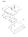
Figure 4 ] an exploded perspective view of the contact part of the tire shaping drum ofFigure 1 . - [
Figure 5 ] (a) to (c) are diagrams for explaining the expansion and contraction of the tire shaping drum ofFigure 1 . - [
Figure 6 ] (a) and (b) are diagrams for explaining the motion of spring means of a tire shaping drum showing another embodiment of the present invention. - [
Figure 7 ] a diagram for explaining the conventional tire shaping drum. - An embodiment of the present invention is described below based on the drawings.
- As shown in
Figure 1 , in this embodiment, the tire shaping drum 1 has a rotatably supportedcentral axle 2, adrum part 3 which is disposed radially outward of thecentral axle 2 and which is capable of expansion and contraction, and an expanding/contracting means 4 which links thecentral axle 2 and thedrum part 3. - The expanding/contracting means 4 can change the
drum part 3 from a diameter contracted state Yr to a cylindrical diameter expanded state Ye, or from the diameter expanded state Ye to the diameter contracted state Yr. - The tire shaping drum 1 in the diameter expanded state Ye provides a cylindrical outer surface S for the
drum part 3. On the outer surface S, for example, a sheet-like rubber material is wound along the circumferential direction.
Both ends of the wound rubber material are spliced, and a cylindrical tire member is formed and shaped.
After the forming and shaping of the tire member, thedrum part 3 is made in the diameter contracted state Yr by the expanding/contracting means 4.
The tire member is removed from one side of thecentral axle 2 in the axial direction. - The
central axle 2, for example, comprises a rotatably-supported central axlemain portion 5, andcylindrical mounting members 6 fitted onto both end portions of the central axlemain portion 5.
For example, like a cantilever, one end of the central axlemain portion 5 is supported by a main frame (not shown) of the shaping drum 1 through a bearing or the like,
As shown inFigure 2(a) , on the axially inside of themounting member 6, there is provided with a radially outwardly extending substantially disk-shaped side plate 7. - As shown in
Figure 1 , the expanding/contracting means 4 comprises a plurality of expansion-and-contraction parts 4a arranged in the circumferential direction of theside plate 7. As shown inFigure 2(a) , the expansion-and-contraction part 4a has acylinder device 11 fixed to theside plate 7, aslide part 9 moved by thecylinder device 11, and aguide part 12 for guiding theslide part 9 in the radial direction. In this embodiment, the expanding/contractingmeans 4 is disposed in each end side of thecentral axle 2 in the axial direction.
For example, eight expansion-and-contraction parts 4a are arranged at regular intervals in the circumferential direction of theside plate 7. - The
cylinder device 11 is, for example, supported by theside plate 7 through amounting bracket 16 attached to the axiallyinner surface 7b of theside plate 7.
Thecylinder device 11 has a cylindermain portion 17, arod 18 moving in and out of the cylindermain portion 17, and a pair ofchannels main portion 17. Therod 18 reciprocates radially of thecentral axle 2 by operating fluid, e.g. air, oil or the like loaded in the cylindermain portion 17 through thechannel - As shown in
Figure 2 (a) or (b) , theslide part 9 has
a slide partmain portion 14 disposed on the axialouter surface 7a side of theside plate 7, and
a plate-like metal part 10 for mounting fixed to the radially outer end of the slide partmain portion 14.
The slide partmain portion 14 is a plate whose section is substantially T-shaped, and it is provided with a pair offlange parts 15 which are guided along theguide part 12 fixed to theouter surface 7a of theside plate 7. - On the radially outside of the
side plate 7, themetal part 10 for mounting extends to the axially inside of theside plate 7, and the tip of therod 18 of thecylinder device 11 is fixed thereto.
when therod 18 of thecylinder device 11 reciprocates, theslide part 9 is moved toward the radially inside or outside while the slide partmain portion 14 is guided by theguide part 12. - As shown in
Figure 3 , thedrum part 3 is composed offirst segments 20 andsecond segments 21 disposed alternately in the circumferential direction.
By thefirst segments 20 and thesecond segments 21 which are seriated, thedrum part 3 is formed substantially in the form of a ring. - The
first segment 20 has first end faces 22 at both ends in the circumferential direction, which are inclined so that the length in the circumferential direction of the segment increases towards the radially inside, and aninner surface 23 extending between the first end faces 22 and 22 on the radially inside. Themetal part 10 for mounting of theslide part 9 is fixed to the central portion of theinner surface 23 of thefirst segments 20. - The
second segment 21 has second end faces 24 at both ends in the circumferential direction, which are inclined so that the length in the circumferential direction of the segment decreases towards the radially inside, and aninner surface 25 extending between the second end faces 24 on the radially inside. Themetal part 10 for mounting of theslide part 9 is fixed to the central portion of theinner surface 25 of thesecond segments 21. - The shaping drum 1 has a backlash prevention means 28 for preventing backlash between the first end faces 22 and the second end faces 24 when the
drum part 3 is in the diameter expanded state Ye. Consequently, the first end faces 22 and the second end faces 24 closely contact with each other, and backlash between thefirst segments 20 and thesecond segments 21 is prevented. Therefore, it is possible to prevent the decrease in the circularity of thedrum part 3, the variation of the outer diameter of thedrum part 3 and the like. - The backlash prevention means 28 in this embodiment comprises a
contact part 29 provided on each side of thefirst segment 20 in the circumferential direction.
Thecontact part 29 extends in the circumferential direction from the radiallyinner edge 22e of thefirst end face 22 of thefirst segment 20.
Consequently, thecontact part 29 radially outwardly pushes theinner surface 25 of thesecond segment 21 when thedrum part 3 is in the diameter expanded state Ye. - As shown in
Figure 4 , thecontact part 29 comprises amain portion 32 fixed to theinner surface 23 of thefirst segment 20, and a shock-absorbingcushion material 33 fixed to the radiallyouter surface 32a of themain portion 32. In this embodiment, thecontact part 29 is provided on each side of thefirst segment 20 in the circumferential direction. On each side of thefirst segment 20 in the circumferential direction, plural units are disposed at predetermined intervals in the axial direction of thecentral axle 2. - The
main portion 32 is formed of a metal material, for example, iron and the like. Themain portion 32 is composed of a circular-arc-shapedmain portion block 35, and ashim body 36 formed of a thin plate or the like fixed between themain portion block 35 and thefirst segment 20. Consequently, the thickness t in the radial direction of thecontact part 29 becomes equal to the summation of the thickness in the radial direction of themain portion block 35 and the thickness in the radial direction of theshim body 36. - The
cushion material 33 is formed of, for example, a rubber material. More preferably, thecushion material 33 is formed of a rubber material containing reinforcing thread. Thecushion material 33 is fixed to the radiallyouter surface 32a of themain portion 32.
Since thecushion material 33 is fixed to thecontact part 29, a shock at the time of contacting between thecontact part 29 and thesecond segment 21 can be mitigated by deformation of thecushion material 33.
At the same time, due to the elasticity of thecushion material 33, thesecond segment 21 is pushed radially outward, and the backlash thereof is prevented.
For example, the thickness in the radial direction of thecushion material 33 is set to be the same as that of theshim body 36.
For example, the thickness t in the radial direction of thecontact part 29 is set to be constant in the circumferential direction of the drum. - For example, it is preferred that the thickness t in the radial direction of the
contact part 29 is set in a range of from 8 to 25 mm. If the thickness t in the radial direction of thecontact part 29 is less than 8 mm, deformation of thecontact part 29 can be caused by contacting with theinner surface 25 of thesecond segment 21. If the thickness t in the radial direction of thecontact part 29 is more than 25 mm, wear of theflange parts 15 and guidegrooves 12 can be accelerated by the weight of thecontact part 29. From these standpoints, the thickness t in the radial direction of thecontact part 29 is more preferably in a range of 12 to 18 mm. - In order to disperse the load evenly on the
segments contact parts 29 come into contact with thesecond segments 21, it is preferable for thecontact part 29 that, for example, about 3/7 of the circumferential length r is fixed to thefirst segment 20, and about 4/7 of the circumferential length r contacts with thesecond segment 21. In order to provide strength for the fixed portion between thecontact part 29 and thefirst segment 20, the circumferential length r of thecontact part 29 is preferably set to such a length that it is possible to form a bolt-hole 34 for inserting at least one bolt.
Based on this standpoint, the circumferential length r of thecontact part 29 is preferably in a range of 40 to 120 mm, more preferably in a range of 50 to 90 mm. - The length in the axial direction 1 of the
contact part 29 is preferably in a range of 20 to 100 mm.
If the length in the axial direction 1 of thecontact part 29 is less than 20 mm, it is difficult to form the bolt-hole 34. If the length in the axial direction 1 of thecontact part 29 is more than 100 mm, the weight of thecontact part 29 is increased, and wear of theguide groove 12 and theflange parts 15 can be accelerated.
From these standpoints, the length in the axial direction 1 of thecontact part 29 is more preferably in a range of 35 to 65 mm. - Next, function of the present invention will be described.
- In the above-mentioned shaping drum 1, as shown in
Figure 5 (a) , when the diameter of thedrum part 3 is expanded, therods 18 of the cylinder devices 11 (shown inFigure 2 (a) ) connected to thesecond segments 21 extend.
Thereby, as shown inFigure 5 (b) , thesecond segments 21 are moved radially outwardly from their contraction position YrA to their expansion position YeA. - After the
second segments 21 have been moved to the expansion position YeA, therods 18 of the cylinder devices 11 (shown inFigure 2 (a) ) connected to thefirst segments 20 are extended from the state shown inFigure 5 (b) .
Thereby, as shown inFigure 5 (c) , thefirst segments 20 are moved radially outwardly from their contraction position YrB to the expansion position YeB in the diameter expanded state Ye. - when the
drum part 3 becomes the diameter expanded state Ye, the first end faces 22 of thefirst segments 20 come into contact with the second end faces 24 of thesecond segments 21. Thecontact parts 29, as the backlash prevention means, radially outwardly push theinner surfaces 25 of thesecond segments 21. Consequently, thesecond segments 21 are prevented from moving radially inward.
Accordingly, theinner surfaces 23 of thefirst segments 20 and theinner surfaces 25 of thesecond segments 21 are aligned continuously in the circumferential direction, and the first end faces and the second end faces closely contact with each other. And the backlash of thedrum part 3 can be prevented (mutual displacement can be prevented). - On the occasion of the contraction of the
drum part 3, contrary to the above-mentioned occasion of the expansion of thedrum part 3, starting from the diameter expanded state Ye shown inFigure 5 (c) , thefirst segments 20 are first moved radially inwardly from the expansion position YeB to the contraction position YrB. Then, from the state shown inFigure 5 (b) , thesecond segments 21 are moved radially inwardly from the expansion position YeA to the contraction position YrA.
Thereby, thedrum part 3 is contracted to the diameter contracted state Yr shown inFigure 5 (a) . - In
Figure 6 , another embodiment of the backlash prevention means 28 in the present invention is shown. In this embodiment, the same reference signs are used for the same structures as explained above, and the detailed description therefor is omitted. - As shown in
Figure 6 (a) or (b) , the shaping drum 1' in this embodiment comprises, as the backlash prevention means 28, spring means 30 for closely contacting the first end faces 22 of thefirst segments 20 and the second end faces 24 of thesecond segments 21 with each other when in the diameter expanded state Ye of thedrum part 3. - The spring means 30 link the
adjacent slide parts 9 in the circumferential direction.
Thereby, in the diameter expanded state Ye of thedrum part 3, the first end faces 22 of thefirst segments 20 and the second end faces 24 of thesecond segments 21 are biased toward such directions that they can contact with each other. For example, the spring means 30 are coiled springs stretched between the circumferentiallyadjacent metal parts - As shown in
Figure 6 (a) , when thedrum part 3 is in the diameter contracted state Yr, the spring means 30 becomes substantially zero stretched and in a no-load state. On the other hand, as shown inFigure 6 (b) , when thedrum part 3 is in the diameter expanded state Ye, the spring means 30 are stretched between theslide parts 9.
when thedrum part 3 is in the diameter expanded state Ye, the stretched spring means 30 bias theslide parts 9 at both ends toward such directions that they attract each other.
Therefore, thefirst end face 22 of thefirst segment 20 supported by each of theslide parts 9 closely contacts with thesecond end face 24 of thesecond segment 21. - Alternatively to the coiled spring, the spring means 30 may be of a structure having an elastic body, rubber or the like, having a reduction percentage similar to that of the coiled spring.
- while description has been made of embodiments of the present invention, the present invention should not be limited to these embodiments; it is possible to carry out the invention by changing into various embodiments.
For example, the backlash prevention means 28 may be of such a structure that includes thecontact parts 29 and the spring means 30. - By tire shaping drums having specifications listed in Table 1, a carcass ply for 155/65R14 size was experimentally manufactured as a cylindrical tire member.
Then, the state of the splice portion of the cylindrical carcass, the state of imbalance of material occurring in a tire using the carcass, the durability of the tire shaping drum, and a comprehensive general evaluation were evaluated. The evaluation methods were as follows. - The state of the splice portion of the carcass was evaluated by comparison with a carcass (comparative example) experimentally manufactured by a conventional shaping drum shown in
Figure 7 . The larger value shows that a better carcass in accordance with the shape of the drum part could be formed and shaped. - The state of imbalance of material occurring in the tire was evaluated by comparison with a tire using the carcass (comparative example) experimentally manufactured by the conventional shaping drum shown in
Figure 7 . The larger value shows that tire defects were lessened. - The state of wear of the shaping drum was observed after the carcass was experimentally manufactured plural times, and the durability of the shaping drum was evaluated by comparison with the shaping drum shown in
Figure 7 . The larger value shows that the wear was less. - The above-mentioned state of splice portion, the state of imbalance and the durability of the shaping drum were comprehensively evaluated, and the general evaluation was evaluated by comparison with the shaping drum shown in
Figure 7 . The larger value is better.[Table 1] comparative example embodiment 1 embodiment 2embodiment 3embodiment 4embodiment 5embodiment 6embodiment 7embodiment 8 embodiment 9embodiment 10specifications backlash prevention means none springs contact parts both both both both both both both both contact part thickness t (mm) --- --- 15 8 15 25 15 15 15 15 15 contact part axial length l (mm) --- --- 50 50 50 50 20 100 50 50 50 contact part circum. length r (mm) --- --- 70 70 70 70 70 70 40 120 70 existence or nonexistence of cushion material nonexistence nonexistence existence existence existence existence existence existence existence existence nonexistence evaluation splice state 95 100 105 120 160 160 130 160 140 160 110 imbalance state 95 100 105 115 130 130 118 130 120 130 102 durability of shaping drum 102 100 98 98 95 93 98 91 98 93 80 general evaluation 100 110 115 118 130 125 120 123 122 125 105 - As shown in Table 1, the carcasses formed and shaped by the use of the tire shaping drums of the present invention were reduced in flabbiness, and it could be confirmed that the tires using them were reduced in defectiveness and had high quality.
-
- 1
- tire shaping drum
- 2
- central axle
- 3
- drum part
- 4
- expanding/contracting means
- 9
- slide part
- 20
- first segment
- 21
- second segment
- 22
- first end face
- 23
- inner surface
- 24
- second end face
- 25
- inner surface
- 28
- backlash prevention means
- 29
- contact part
- 30
- spring means
- Yr
- diameter contracted state
- Ye
- diameter expanded state
- t
- thickness in the radial direction
- r
- length in the radial direction
- l
- length in the axial direction
Claims (8)
- A tire shaping drum having
a central axle which is rotatably supported,
a drum part which is disposed radially outward of the central axle and which is capable of expansion and contraction, and
an expanding/contracting means which links the central axle and the drum part and which changes the drum part into a diameter contracted state or a cylindrical diameter expanded state, wherein
the drum part becomes annular by seriating first segments and second segments alternately in the circumferential direction,
the first segment has, at both ends in the circumferential direction thereof, first end faces inclined so that the length in the circumferential direction of the segment increases towards the radially inside,
the second segment has, at both ends in the circumferential direction thereof, second end faces inclined so that the length in the circumferential direction of the segment decreases towards the radially inside, and
the first end faces contact with the second end faces when the drum part is in a diameter expanded state, characterized by being provided with a backlash prevention means for preventing backlash between the first end faces and the second end faces when in the diameter expanded state. - The tire shaping drum as set forth in claim 1, wherein the backlash prevention means is provided on the first segments and comprises contact parts which radially outwardly push inner surfaces extending between the second end faces on the radially inside of the second segments when the drum part is in the diameter expanded state.
- The tire shaping drum as set forth in claim 2, wherein the contact parts extend in the circumferential direction from radially inner edges of the first end faces of the first segments.
- The tire shaping drum as set forth in claim 2 or 3, wherein the contact parts are provided on both sides of the first segments in the circumferential direction.
- The tire shaping drum as set forth in any one of claims 2-4, wherein the contact part comprises a circular-arc-shaped main portion fixed to an inner surface between the first end faces on the radially inside of the first segment, and a shock-absorbing cushion material fixed to the radially outer surface of the main portion.
- The tire shaping drum as set forth in any one of claims 2-5, wherein the contact part has a thickness in the radial direction of 8 to 25 mm, a length in the circumferential direction of 40 to 120 mm, and a length in the axial direction of the drum of 20 to 100 mm.
- The tire shaping drum as set forth in any one of claims 1-6, wherein the backlash prevention means comprises spring means for closely contacting the first end faces of the first segments and the second end faces of the second segments with each other when in the diameter expanded state.
- The tire shaping drum as set forth in claim 7, wherein the expanding/contracting means has a plurality of slide parts movable in the radial direction, each first segment and each second segment are supported by each slide part, and the spring means link the adjacent slide parts in the circumferential direction.
Applications Claiming Priority (2)
| Application Number | Priority Date | Filing Date | Title |
|---|---|---|---|
| JP2012148782A JP5767610B2 (en) | 2012-07-02 | 2012-07-02 | Tire molding drum |
| PCT/JP2013/062760 WO2014006970A1 (en) | 2012-07-02 | 2013-05-02 | Tire shaping drum |
Publications (3)
| Publication Number | Publication Date |
|---|---|
| EP2860022A1 true EP2860022A1 (en) | 2015-04-15 |
| EP2860022A4 EP2860022A4 (en) | 2016-04-13 |
| EP2860022B1 EP2860022B1 (en) | 2017-07-26 |
Family
ID=49881732
Family Applications (1)
| Application Number | Title | Priority Date | Filing Date |
|---|---|---|---|
| EP13813017.4A Not-in-force EP2860022B1 (en) | 2012-07-02 | 2013-05-02 | Tire shaping drum |
Country Status (5)
| Country | Link |
|---|---|
| US (1) | US9849643B2 (en) |
| EP (1) | EP2860022B1 (en) |
| JP (1) | JP5767610B2 (en) |
| CN (1) | CN104395061B (en) |
| WO (1) | WO2014006970A1 (en) |
Cited By (1)
| Publication number | Priority date | Publication date | Assignee | Title |
|---|---|---|---|---|
| WO2023119068A1 (en) * | 2021-12-21 | 2023-06-29 | Pirelli Tyre S.P.A. | Process and apparatus for manufacturing annular components of tyres for vehicle wheels |
Families Citing this family (8)
| Publication number | Priority date | Publication date | Assignee | Title |
|---|---|---|---|---|
| US10328647B2 (en) * | 2013-08-12 | 2019-06-25 | Davian Enterprises, LLC | Expandable belt and tread drum having irregular segment profiles |
| JP2016043521A (en) * | 2014-08-20 | 2016-04-04 | 住友ゴム工業株式会社 | Tire molding former |
| CN104228097A (en) * | 2014-09-20 | 2014-12-24 | 揭阳市天阳模具有限公司 | Seamless belt beam layer attaching drum |
| JP6870375B2 (en) * | 2017-02-23 | 2021-05-12 | 住友ゴム工業株式会社 | Tire molding equipment |
| NL2018566B1 (en) * | 2017-03-23 | 2018-10-03 | Vmi Holland Bv | Tire building drum and method for operating said tire building drum |
| CN106903915B (en) * | 2017-04-26 | 2023-06-27 | 青岛森麒麟轮胎股份有限公司 | Forming drum and side ring pair |
| CN110920113A (en) * | 2019-12-27 | 2020-03-27 | 萨驰华辰机械(苏州)有限公司 | Tire forming drum and tire forming method |
| CN112388999B (en) * | 2020-10-30 | 2022-11-11 | 潍坊市跃龙橡胶有限公司 | Laminating drum laminating process of all-steel one-step three-drum forming machine |
Family Cites Families (21)
| Publication number | Priority date | Publication date | Assignee | Title |
|---|---|---|---|---|
| US1792462A (en) * | 1927-08-31 | 1931-02-10 | Akron Standard Mold Co | Tire-building drum |
| US2042498A (en) * | 1930-03-18 | 1936-06-02 | Akron Standard Mold Co | Collapsible tire-band form |
| NL111387C (en) * | 1958-01-02 | |||
| US3237199A (en) | 1963-04-26 | 1966-02-22 | Tire building apparatus | |
| GB1568858A (en) * | 1977-03-10 | 1980-06-04 | Vni I Konstrukt I Oborud Dlya | Tyre-building drum |
| US4425180A (en) * | 1981-07-08 | 1984-01-10 | Vsesojuzny Nauchno-Issledovatelsky I Konstruktorsky Institut Po Oborudovaniju Dlya Shinnoi Promyshlennosti | Tire casing assembly drum |
| GB8403351D0 (en) * | 1984-02-08 | 1984-03-14 | Wyko Equipment Ltd | Tyre building drum |
| JP2568020B2 (en) * | 1991-11-13 | 1996-12-25 | 住友ゴム工業株式会社 | Reinforcement structure manufacturing method |
| US5320701A (en) | 1992-11-04 | 1994-06-14 | Illinois Tool Works Inc. | Tire building drum |
| US5618374A (en) * | 1994-02-10 | 1997-04-08 | Wyko, Inc. | Belt and tread drum for vehicle tire making machine |
| US6390166B1 (en) | 2000-05-19 | 2002-05-21 | Wyko, Inc. | Expandable mandrel having adjustable width |
| JP4704602B2 (en) * | 2001-05-21 | 2011-06-15 | 住友ゴム工業株式会社 | Sidewall pasting former |
| US6571682B2 (en) * | 2001-07-31 | 2003-06-03 | Wyko, Inc. | Apparatus for converting circular motion to radial motion |
| US7980042B2 (en) * | 2006-01-17 | 2011-07-19 | LRM Industries International Inc. | Molded panel, molded panel system and connection system |
| KR100802085B1 (en) * | 2006-10-11 | 2008-02-11 | 한국타이어 주식회사 | Variable molding drum device of tire |
| JP2009160845A (en) * | 2008-01-08 | 2009-07-23 | Sumitomo Rubber Ind Ltd | Tire molding drum |
| US8056597B2 (en) * | 2008-04-10 | 2011-11-15 | Bps Engineering, Llc | Cam follower assembly for thin walled cylinder of scroll shaping drum used in tire construction |
| JP4510907B2 (en) * | 2008-05-16 | 2010-07-28 | 住友ゴム工業株式会社 | Tire member molding drum |
| JP4616905B2 (en) * | 2008-08-26 | 2011-01-19 | 住友ゴム工業株式会社 | Molding drum device and method for producing run-flat tire using the same |
| JP4897853B2 (en) * | 2009-06-10 | 2012-03-14 | 住友ゴム工業株式会社 | Tire molding drum |
| DE102011077569A1 (en) * | 2011-06-15 | 2012-12-20 | Herbert Maschinenbau GmbH & Co. KG | drum |
-
2012
- 2012-07-02 JP JP2012148782A patent/JP5767610B2/en not_active Expired - Fee Related
-
2013
- 2013-05-02 CN CN201380032593.3A patent/CN104395061B/en not_active Expired - Fee Related
- 2013-05-02 WO PCT/JP2013/062760 patent/WO2014006970A1/en not_active Ceased
- 2013-05-02 EP EP13813017.4A patent/EP2860022B1/en not_active Not-in-force
- 2013-05-02 US US14/409,016 patent/US9849643B2/en not_active Expired - Fee Related
Cited By (1)
| Publication number | Priority date | Publication date | Assignee | Title |
|---|---|---|---|---|
| WO2023119068A1 (en) * | 2021-12-21 | 2023-06-29 | Pirelli Tyre S.P.A. | Process and apparatus for manufacturing annular components of tyres for vehicle wheels |
Also Published As
| Publication number | Publication date |
|---|---|
| US20150190976A1 (en) | 2015-07-09 |
| JP2014008745A (en) | 2014-01-20 |
| US9849643B2 (en) | 2017-12-26 |
| CN104395061A (en) | 2015-03-04 |
| JP5767610B2 (en) | 2015-08-19 |
| CN104395061B (en) | 2017-03-08 |
| EP2860022B1 (en) | 2017-07-26 |
| WO2014006970A1 (en) | 2014-01-09 |
| EP2860022A4 (en) | 2016-04-13 |
Similar Documents
| Publication | Publication Date | Title |
|---|---|---|
| EP2860022B1 (en) | Tire shaping drum | |
| US6318434B1 (en) | Tire building drum with turn-up apparatus | |
| EP2698243B1 (en) | Sleeveless tire building drum | |
| US7491285B2 (en) | Method for molding bead portion of green tire and bead portion molding device | |
| US20050244528A1 (en) | Tyre drum with turn-up mechanism for building an unvulcanized tyre | |
| EP3378636B1 (en) | Belt drum | |
| US5164035A (en) | Tire building apparatus | |
| RU2728496C2 (en) | Tire and method for production of tire circular carcass | |
| US6491081B2 (en) | Method of manufacturing radial tire having wound band | |
| KR102376820B1 (en) | Tire Building Drums and Methods for Tire Building | |
| JP6848692B2 (en) | Molding drum | |
| US10328651B2 (en) | Rigid core mold and method for manufacturing pneumatic tire using the same | |
| JP5425515B2 (en) | Pneumatic tire | |
| JP2025074523A (en) | Raw tire building equipment | |
| JP2019119167A (en) | Tire molding machine | |
| JP6870375B2 (en) | Tire molding equipment | |
| EP2647493B1 (en) | Tire manufacturing method | |
| JP7554614B2 (en) | Method for forming band member | |
| JP3234773B2 (en) | Tread ring forming method and apparatus used therefor | |
| JP2004074827A (en) | Pneumatic radial tire | |
| JP2006224521A (en) | Tire molding machine |
Legal Events
| Date | Code | Title | Description |
|---|---|---|---|
| PUAI | Public reference made under article 153(3) epc to a published international application that has entered the european phase |
Free format text: ORIGINAL CODE: 0009012 |
|
| 17P | Request for examination filed |
Effective date: 20150105 |
|
| AK | Designated contracting states |
Kind code of ref document: A1 Designated state(s): AL AT BE BG CH CY CZ DE DK EE ES FI FR GB GR HR HU IE IS IT LI LT LU LV MC MK MT NL NO PL PT RO RS SE SI SK SM TR |
|
| AX | Request for extension of the european patent |
Extension state: BA ME |
|
| DAX | Request for extension of the european patent (deleted) | ||
| RA4 | Supplementary search report drawn up and despatched (corrected) |
Effective date: 20160314 |
|
| RIC1 | Information provided on ipc code assigned before grant |
Ipc: B29D 30/24 20060101AFI20160308BHEP Ipc: B29D 30/26 20060101ALI20160308BHEP |
|
| GRAP | Despatch of communication of intention to grant a patent |
Free format text: ORIGINAL CODE: EPIDOSNIGR1 |
|
| STAA | Information on the status of an ep patent application or granted ep patent |
Free format text: STATUS: GRANT OF PATENT IS INTENDED |
|
| INTG | Intention to grant announced |
Effective date: 20170301 |
|
| GRAS | Grant fee paid |
Free format text: ORIGINAL CODE: EPIDOSNIGR3 |
|
| GRAA | (expected) grant |
Free format text: ORIGINAL CODE: 0009210 |
|
| STAA | Information on the status of an ep patent application or granted ep patent |
Free format text: STATUS: THE PATENT HAS BEEN GRANTED |
|
| AK | Designated contracting states |
Kind code of ref document: B1 Designated state(s): AL AT BE BG CH CY CZ DE DK EE ES FI FR GB GR HR HU IE IS IT LI LT LU LV MC MK MT NL NO PL PT RO RS SE SI SK SM TR |
|
| REG | Reference to a national code |
Ref country code: GB Ref legal event code: FG4D |
|
| REG | Reference to a national code |
Ref country code: CH Ref legal event code: EP |
|
| REG | Reference to a national code |
Ref country code: AT Ref legal event code: REF Ref document number: 912029 Country of ref document: AT Kind code of ref document: T Effective date: 20170815 |
|
| REG | Reference to a national code |
Ref country code: IE Ref legal event code: FG4D |
|
| REG | Reference to a national code |
Ref country code: DE Ref legal event code: R096 Ref document number: 602013024164 Country of ref document: DE |
|
| REG | Reference to a national code |
Ref country code: NL Ref legal event code: MP Effective date: 20170726 |
|
| REG | Reference to a national code |
Ref country code: LT Ref legal event code: MG4D |
|
| REG | Reference to a national code |
Ref country code: AT Ref legal event code: MK05 Ref document number: 912029 Country of ref document: AT Kind code of ref document: T Effective date: 20170726 |
|
| PG25 | Lapsed in a contracting state [announced via postgrant information from national office to epo] |
Ref country code: NL Free format text: LAPSE BECAUSE OF FAILURE TO SUBMIT A TRANSLATION OF THE DESCRIPTION OR TO PAY THE FEE WITHIN THE PRESCRIBED TIME-LIMIT Effective date: 20170726 Ref country code: LT Free format text: LAPSE BECAUSE OF FAILURE TO SUBMIT A TRANSLATION OF THE DESCRIPTION OR TO PAY THE FEE WITHIN THE PRESCRIBED TIME-LIMIT Effective date: 20170726 Ref country code: HR Free format text: LAPSE BECAUSE OF FAILURE TO SUBMIT A TRANSLATION OF THE DESCRIPTION OR TO PAY THE FEE WITHIN THE PRESCRIBED TIME-LIMIT Effective date: 20170726 Ref country code: FI Free format text: LAPSE BECAUSE OF FAILURE TO SUBMIT A TRANSLATION OF THE DESCRIPTION OR TO PAY THE FEE WITHIN THE PRESCRIBED TIME-LIMIT Effective date: 20170726 Ref country code: AT Free format text: LAPSE BECAUSE OF FAILURE TO SUBMIT A TRANSLATION OF THE DESCRIPTION OR TO PAY THE FEE WITHIN THE PRESCRIBED TIME-LIMIT Effective date: 20170726 Ref country code: SE Free format text: LAPSE BECAUSE OF FAILURE TO SUBMIT A TRANSLATION OF THE DESCRIPTION OR TO PAY THE FEE WITHIN THE PRESCRIBED TIME-LIMIT Effective date: 20170726 Ref country code: NO Free format text: LAPSE BECAUSE OF FAILURE TO SUBMIT A TRANSLATION OF THE DESCRIPTION OR TO PAY THE FEE WITHIN THE PRESCRIBED TIME-LIMIT Effective date: 20171026 |
|
| PG25 | Lapsed in a contracting state [announced via postgrant information from national office to epo] |
Ref country code: ES Free format text: LAPSE BECAUSE OF FAILURE TO SUBMIT A TRANSLATION OF THE DESCRIPTION OR TO PAY THE FEE WITHIN THE PRESCRIBED TIME-LIMIT Effective date: 20170726 Ref country code: GR Free format text: LAPSE BECAUSE OF FAILURE TO SUBMIT A TRANSLATION OF THE DESCRIPTION OR TO PAY THE FEE WITHIN THE PRESCRIBED TIME-LIMIT Effective date: 20171027 Ref country code: IS Free format text: LAPSE BECAUSE OF FAILURE TO SUBMIT A TRANSLATION OF THE DESCRIPTION OR TO PAY THE FEE WITHIN THE PRESCRIBED TIME-LIMIT Effective date: 20171126 Ref country code: RS Free format text: LAPSE BECAUSE OF FAILURE TO SUBMIT A TRANSLATION OF THE DESCRIPTION OR TO PAY THE FEE WITHIN THE PRESCRIBED TIME-LIMIT Effective date: 20170726 Ref country code: BG Free format text: LAPSE BECAUSE OF FAILURE TO SUBMIT A TRANSLATION OF THE DESCRIPTION OR TO PAY THE FEE WITHIN THE PRESCRIBED TIME-LIMIT Effective date: 20171026 Ref country code: LV Free format text: LAPSE BECAUSE OF FAILURE TO SUBMIT A TRANSLATION OF THE DESCRIPTION OR TO PAY THE FEE WITHIN THE PRESCRIBED TIME-LIMIT Effective date: 20170726 Ref country code: PL Free format text: LAPSE BECAUSE OF FAILURE TO SUBMIT A TRANSLATION OF THE DESCRIPTION OR TO PAY THE FEE WITHIN THE PRESCRIBED TIME-LIMIT Effective date: 20170726 |
|
| REG | Reference to a national code |
Ref country code: FR Ref legal event code: PLFP Year of fee payment: 6 |
|
| PG25 | Lapsed in a contracting state [announced via postgrant information from national office to epo] |
Ref country code: DK Free format text: LAPSE BECAUSE OF FAILURE TO SUBMIT A TRANSLATION OF THE DESCRIPTION OR TO PAY THE FEE WITHIN THE PRESCRIBED TIME-LIMIT Effective date: 20170726 Ref country code: RO Free format text: LAPSE BECAUSE OF FAILURE TO SUBMIT A TRANSLATION OF THE DESCRIPTION OR TO PAY THE FEE WITHIN THE PRESCRIBED TIME-LIMIT Effective date: 20170726 Ref country code: CZ Free format text: LAPSE BECAUSE OF FAILURE TO SUBMIT A TRANSLATION OF THE DESCRIPTION OR TO PAY THE FEE WITHIN THE PRESCRIBED TIME-LIMIT Effective date: 20170726 |
|
| REG | Reference to a national code |
Ref country code: DE Ref legal event code: R097 Ref document number: 602013024164 Country of ref document: DE |
|
| PG25 | Lapsed in a contracting state [announced via postgrant information from national office to epo] |
Ref country code: SK Free format text: LAPSE BECAUSE OF FAILURE TO SUBMIT A TRANSLATION OF THE DESCRIPTION OR TO PAY THE FEE WITHIN THE PRESCRIBED TIME-LIMIT Effective date: 20170726 Ref country code: SM Free format text: LAPSE BECAUSE OF FAILURE TO SUBMIT A TRANSLATION OF THE DESCRIPTION OR TO PAY THE FEE WITHIN THE PRESCRIBED TIME-LIMIT Effective date: 20170726 Ref country code: EE Free format text: LAPSE BECAUSE OF FAILURE TO SUBMIT A TRANSLATION OF THE DESCRIPTION OR TO PAY THE FEE WITHIN THE PRESCRIBED TIME-LIMIT Effective date: 20170726 Ref country code: IT Free format text: LAPSE BECAUSE OF FAILURE TO SUBMIT A TRANSLATION OF THE DESCRIPTION OR TO PAY THE FEE WITHIN THE PRESCRIBED TIME-LIMIT Effective date: 20170726 |
|
| PLBE | No opposition filed within time limit |
Free format text: ORIGINAL CODE: 0009261 |
|
| STAA | Information on the status of an ep patent application or granted ep patent |
Free format text: STATUS: NO OPPOSITION FILED WITHIN TIME LIMIT |
|
| 26N | No opposition filed |
Effective date: 20180430 |
|
| PG25 | Lapsed in a contracting state [announced via postgrant information from national office to epo] |
Ref country code: SI Free format text: LAPSE BECAUSE OF FAILURE TO SUBMIT A TRANSLATION OF THE DESCRIPTION OR TO PAY THE FEE WITHIN THE PRESCRIBED TIME-LIMIT Effective date: 20170726 |
|
| REG | Reference to a national code |
Ref country code: CH Ref legal event code: PL |
|
| GBPC | Gb: european patent ceased through non-payment of renewal fee |
Effective date: 20180502 |
|
| REG | Reference to a national code |
Ref country code: BE Ref legal event code: MM Effective date: 20180531 |
|
| PG25 | Lapsed in a contracting state [announced via postgrant information from national office to epo] |
Ref country code: MC Free format text: LAPSE BECAUSE OF FAILURE TO SUBMIT A TRANSLATION OF THE DESCRIPTION OR TO PAY THE FEE WITHIN THE PRESCRIBED TIME-LIMIT Effective date: 20170726 |
|
| REG | Reference to a national code |
Ref country code: IE Ref legal event code: MM4A |
|
| PG25 | Lapsed in a contracting state [announced via postgrant information from national office to epo] |
Ref country code: CH Free format text: LAPSE BECAUSE OF NON-PAYMENT OF DUE FEES Effective date: 20180531 Ref country code: LI Free format text: LAPSE BECAUSE OF NON-PAYMENT OF DUE FEES Effective date: 20180531 |
|
| PG25 | Lapsed in a contracting state [announced via postgrant information from national office to epo] |
Ref country code: LU Free format text: LAPSE BECAUSE OF NON-PAYMENT OF DUE FEES Effective date: 20180502 |
|
| PG25 | Lapsed in a contracting state [announced via postgrant information from national office to epo] |
Ref country code: GB Free format text: LAPSE BECAUSE OF NON-PAYMENT OF DUE FEES Effective date: 20180502 Ref country code: IE Free format text: LAPSE BECAUSE OF NON-PAYMENT OF DUE FEES Effective date: 20180502 |
|
| PG25 | Lapsed in a contracting state [announced via postgrant information from national office to epo] |
Ref country code: BE Free format text: LAPSE BECAUSE OF NON-PAYMENT OF DUE FEES Effective date: 20180531 |
|
| PGFP | Annual fee paid to national office [announced via postgrant information from national office to epo] |
Ref country code: DE Payment date: 20190416 Year of fee payment: 7 |
|
| PGFP | Annual fee paid to national office [announced via postgrant information from national office to epo] |
Ref country code: FR Payment date: 20190410 Year of fee payment: 7 |
|
| PG25 | Lapsed in a contracting state [announced via postgrant information from national office to epo] |
Ref country code: MT Free format text: LAPSE BECAUSE OF NON-PAYMENT OF DUE FEES Effective date: 20180502 |
|
| PG25 | Lapsed in a contracting state [announced via postgrant information from national office to epo] |
Ref country code: TR Free format text: LAPSE BECAUSE OF FAILURE TO SUBMIT A TRANSLATION OF THE DESCRIPTION OR TO PAY THE FEE WITHIN THE PRESCRIBED TIME-LIMIT Effective date: 20170726 |
|
| PG25 | Lapsed in a contracting state [announced via postgrant information from national office to epo] |
Ref country code: PT Free format text: LAPSE BECAUSE OF FAILURE TO SUBMIT A TRANSLATION OF THE DESCRIPTION OR TO PAY THE FEE WITHIN THE PRESCRIBED TIME-LIMIT Effective date: 20170726 |
|
| PG25 | Lapsed in a contracting state [announced via postgrant information from national office to epo] |
Ref country code: HU Free format text: LAPSE BECAUSE OF FAILURE TO SUBMIT A TRANSLATION OF THE DESCRIPTION OR TO PAY THE FEE WITHIN THE PRESCRIBED TIME-LIMIT; INVALID AB INITIO Effective date: 20130502 Ref country code: MK Free format text: LAPSE BECAUSE OF NON-PAYMENT OF DUE FEES Effective date: 20170726 Ref country code: CY Free format text: LAPSE BECAUSE OF FAILURE TO SUBMIT A TRANSLATION OF THE DESCRIPTION OR TO PAY THE FEE WITHIN THE PRESCRIBED TIME-LIMIT Effective date: 20170726 |
|
| PG25 | Lapsed in a contracting state [announced via postgrant information from national office to epo] |
Ref country code: AL Free format text: LAPSE BECAUSE OF FAILURE TO SUBMIT A TRANSLATION OF THE DESCRIPTION OR TO PAY THE FEE WITHIN THE PRESCRIBED TIME-LIMIT Effective date: 20170726 |
|
| REG | Reference to a national code |
Ref country code: DE Ref legal event code: R119 Ref document number: 602013024164 Country of ref document: DE |
|
| PG25 | Lapsed in a contracting state [announced via postgrant information from national office to epo] |
Ref country code: FR Free format text: LAPSE BECAUSE OF NON-PAYMENT OF DUE FEES Effective date: 20200531 |
|
| PG25 | Lapsed in a contracting state [announced via postgrant information from national office to epo] |
Ref country code: DE Free format text: LAPSE BECAUSE OF NON-PAYMENT OF DUE FEES Effective date: 20201201 |