EP2859959A1 - Dispenser for sucking back contents remaining in the nozzle outlet - Google Patents
Dispenser for sucking back contents remaining in the nozzle outlet Download PDFInfo
- Publication number
- EP2859959A1 EP2859959A1 EP20130188504 EP13188504A EP2859959A1 EP 2859959 A1 EP2859959 A1 EP 2859959A1 EP 20130188504 EP20130188504 EP 20130188504 EP 13188504 A EP13188504 A EP 13188504A EP 2859959 A1 EP2859959 A1 EP 2859959A1
- Authority
- EP
- European Patent Office
- Prior art keywords
- stem
- contents
- spring
- piston rod
- dispenser
- Prior art date
- Legal status (The legal status is an assumption and is not a legal conclusion. Google has not performed a legal analysis and makes no representation as to the accuracy of the status listed.)
- Granted
Links
Images




Classifications
-
- B—PERFORMING OPERATIONS; TRANSPORTING
- B05—SPRAYING OR ATOMISING IN GENERAL; APPLYING FLUENT MATERIALS TO SURFACES, IN GENERAL
- B05B—SPRAYING APPARATUS; ATOMISING APPARATUS; NOZZLES
- B05B11/00—Single-unit hand-held apparatus in which flow of contents is produced by the muscular force of the operator at the moment of use
- B05B11/01—Single-unit hand-held apparatus in which flow of contents is produced by the muscular force of the operator at the moment of use characterised by the means producing the flow
- B05B11/10—Pump arrangements for transferring the contents from the container to a pump chamber by a sucking effect and forcing the contents out through the dispensing nozzle
- B05B11/1001—Piston pumps
- B05B11/1023—Piston pumps having an outlet valve opened by deformation or displacement of the piston relative to its actuating stem
- B05B11/1026—Piston pumps having an outlet valve opened by deformation or displacement of the piston relative to its actuating stem the piston being deformable and its deformation allowing opening of the outlet
-
- B—PERFORMING OPERATIONS; TRANSPORTING
- B05—SPRAYING OR ATOMISING IN GENERAL; APPLYING FLUENT MATERIALS TO SURFACES, IN GENERAL
- B05B—SPRAYING APPARATUS; ATOMISING APPARATUS; NOZZLES
- B05B11/00—Single-unit hand-held apparatus in which flow of contents is produced by the muscular force of the operator at the moment of use
- B05B11/01—Single-unit hand-held apparatus in which flow of contents is produced by the muscular force of the operator at the moment of use characterised by the means producing the flow
- B05B11/10—Pump arrangements for transferring the contents from the container to a pump chamber by a sucking effect and forcing the contents out through the dispensing nozzle
- B05B11/1042—Components or details
- B05B11/105—Sealing arrangements around pump actuating stem
-
- B—PERFORMING OPERATIONS; TRANSPORTING
- B05—SPRAYING OR ATOMISING IN GENERAL; APPLYING FLUENT MATERIALS TO SURFACES, IN GENERAL
- B05B—SPRAYING APPARATUS; ATOMISING APPARATUS; NOZZLES
- B05B11/00—Single-unit hand-held apparatus in which flow of contents is produced by the muscular force of the operator at the moment of use
- B05B11/01—Single-unit hand-held apparatus in which flow of contents is produced by the muscular force of the operator at the moment of use characterised by the means producing the flow
- B05B11/10—Pump arrangements for transferring the contents from the container to a pump chamber by a sucking effect and forcing the contents out through the dispensing nozzle
- B05B11/1097—Pump arrangements for transferring the contents from the container to a pump chamber by a sucking effect and forcing the contents out through the dispensing nozzle with means for sucking back the liquid or other fluent material in the nozzle after a dispensing stroke
-
- B—PERFORMING OPERATIONS; TRANSPORTING
- B05—SPRAYING OR ATOMISING IN GENERAL; APPLYING FLUENT MATERIALS TO SURFACES, IN GENERAL
- B05B—SPRAYING APPARATUS; ATOMISING APPARATUS; NOZZLES
- B05B11/00—Single-unit hand-held apparatus in which flow of contents is produced by the muscular force of the operator at the moment of use
- B05B11/01—Single-unit hand-held apparatus in which flow of contents is produced by the muscular force of the operator at the moment of use characterised by the means producing the flow
- B05B11/10—Pump arrangements for transferring the contents from the container to a pump chamber by a sucking effect and forcing the contents out through the dispensing nozzle
- B05B11/1042—Components or details
- B05B11/1043—Sealing or attachment arrangements between pump and container
- B05B11/1046—Sealing or attachment arrangements between pump and container the pump chamber being arranged substantially coaxially to the neck of the container
- B05B11/1047—Sealing or attachment arrangements between pump and container the pump chamber being arranged substantially coaxially to the neck of the container the pump being preassembled as an independent unit before being mounted on the container
Definitions
- the present invention relates to a dispenser for sucking back contents, and more particularly to a dispenser for sucking back contents which makes it possible to prevent over consumption of contents in such a way to suck back the contents remaining at an end portion of a nozzle of a button of a dispenser after the contents are discharged and used, and also makes it possible to prevent a container body from being contaminated by contents.
- Common liquid or sticky liquid type cosmetic is stored in a dispenser container and is used as it is discharged by a certain amount.
- the dispenser container is equipped with a dispenser at the top of a container which stores contents. The above dispenser is pumped when a button with a nozzle is pressed for thereby discharging contents from the dispenser container.
- the contents when a user presses the button so as to discharge contents, the contents remains at an end portion of the nozzle after the contents is discharged. In this event, the contents remaining at the end portion of the nozzle may move down and contaminate the container and may be spoiled as it directly contact with air. In worse case, the contents may be hardened and block the nozzle. When such situation occurs, the user first needs to remove the hardened and stuck contents when in use. The contents may be over consumed.
- a dispenser for sucking back contents comprising a body which is engaged to the top of a container body; an engaging body which is engaged to the body and fixes a cylinder and is hollow; a cylinder which is engaged to the bottom of the engaging body and has a content input hole formed at the bottom for inputting contents and a valve member which is opened and closed by the pressure of contents in the content input hole; a stem which passes through the hollow interior of the engaging body and has a support shoulder at an inner surface; a piston rod which is engaged to the stem, the bottom of which piston rod is equipped with a spring support part, and the top of which has a spring engaging protrusion which protrudes in an upward direction; a sealing cap which is installed at the bottom of the stem, the outer surface of the sealing cap coming into close contact with an inner surface of the cylinder; a first spring which is installed in the interior of the cylinder and serves to provide an elastic force to the piston rod; a second spring which is installed surrounding the spring engaging protrusion of the piston rod,
- the second spring is contracted by a support shoulder when the stem descends and recovers for thereby allowing the stem to ascend, so the contents remaining at an end portion of the nozzle is sucked back as much as the distance defined as the support shoulder of the stem and the spring engaging protrusion of the piston rod are spaced apart.
- the sealing cap is made from an elastic material and is contracted by a pressure of the stem when the stem descends and recovers, so the stem is allowed to ascend by a change of the length of the sealing cap, for thereby sucking back the contents remaining at an end portion of the nozzle.
- the present invention is advantageous because it is possible to prevent over consumption of contents in such a way to suck back the contents remaining at an end portion of a nozzle of a button of a dispenser after the contents are discharged and used, and also makes it possible to prevent a container body from being contaminated by contents.
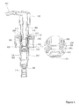
- Figure 1 is a cross sectional view illustrating a construction of a dispenser for sucking back contents according to a preferred embodiment of the present invention.
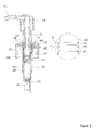
- Figures 2 to 5 are views for explaining a suck-back procedure of contents of a dispenser for sucking back contents according to a preferred embodiment of the present invention.
- Figure 6 is a cross sectional view illustrating a state that a dispenser for sucking back contents is engaged to a container body according to a preferred embodiment of the present invention.
- the dispenser for sucking back contents comprises a body 100, an engaging body 200, a cylinder 300, a stem 400, a piston rod 500, a sealing cap 600, a first spring 700, a second spring 800 and a button 900.
- the body 100 is engaged to the top of the container body 10 which is filled with contents "a" for thereby closing the open top of the container body 10, and the body 100 has an engaging shoulder 110 at its inner side for an engagement to the engaging body 200.
- the engaging body 200 is engaged to the body 100 for thereby fixing the cylinder 300 and has an engaging protrusion 210 at its portion which comes into contact with the engaging shoulder 110, for the engaging protrusion 210 to be fixedly mounted at the engaging shoulder 110 of the body 100.
- the engaging body 200 is formed in a hollow shape for the stem 400 to pass through.
- the cylinder 300 is engaged to the bottom of the engaging body 200 and has a content input hole 310 at its lower side for the content stored in the container body 100 to input. It is preferred that a valve member 320 is installed at the content input hole 310 for the purpose of preventing a reverse flow of contents as it is opened and closed by the pressure of the contents.
- the stem 400 passes through the hollow portion of the engaging body 200 and is formed in a cylindrical shape the top and bottom of which communicate with each other for the contents to pass through.
- a support shoulder 410 supporting the top of the second spring 800.
- the piston rod 500 is inserted into the bottom of the stem 400. A certain space is formed in the longitudinal direction for the sake of the movement of the contents. At the bottom of the piston rod 500 is provided a spring support part 510 supporting the top of the first spring 700 for the piston rod 500 to ascend by means of an elastic force of the first spring 700.
- a spring engaging protrusion 520 which protrudes in the upward direction for the sake of the installation of the second spring 800.
- the spring engaging protrusion 520 serves to prevent the distortion of the second spring 800 and to guide the movements when the second spring 800 contracts and releases as the stem 400 descends and ascends.
- the spring engaging protrusion 520 helps generate a vacuum pressure in the interior of the stem 400 as much as the distance spaced apart from the support shoulder 410 when the stem 400 ascends by means of an elastic force of the second spring 800 for thereby sucking back the contents remaining at the end portion of the nozzle 910.
- the sealing cap 600 Surrounding the stem 400 and the piston rod 500, the sealing cap 600 is installed at the bottom of the stem 400.
- the sealing cap 600 is made from an elastic material, the top of which is supported by the stem 400, the bottom of which is supported by the piston rod 500, so when the stem 400 descends, it is pressurized by the pressure of the stem 400 and then recovers for thereby allowing the stem 400 to ascend.
- a vacuum pressure is generated in the interior of the stem 400 as much as the length changed by a change in the length of the sealing cap 600 which occurs when the sealing cap 600 is compressed and recovers for thereby sucking back the contents remaining at the end portion of the nozzle 910.
- the first spring 700 is installed in the interior of the cylinder 300, the bottom of which first spring is mounted at the spring mounting shoulder 330 formed at the bottom of the inner side of the cylinder 300, the other side of which is supported by the spring support part 510 of the piston rod 500 for thereby generating and transferring an elastic force to the piston rod 500 during the pumping operations.
- the second spring 800 surrounds the spring engaging protrusion 520 of the piston rod 500, the bottom of which second spring is supported by the piston rod 500, the top of which is supported by the support shoulder 410 of the stem 400 for thereby providing an elastic force in the upward direction during pumping operation, so the stem 400 ascends.
- the second spring 800 is contracted by the support shoulder 410 when the stem 400 descends by a pressure of the button 900 and recovers when the pressurization of the button 900 is removed for thereby allowing the stem 400 to ascend, so the support shoulder 410 of the stem 400 and the spring engaging protrusion 520 of the piston rod 500 becomes spaced apart.
- the stem 400 ascends by an elastic force of the second spring 800, and a vacuum space is generated in the interior of the stem 400 as much as the distance "H" defined as the support shoulder 410 and the spring engaging protrusion 520 are spaced apart for thereby sucking back the contents remaining at the end portion of the nozzle 910.
- the button 900 is engaged to the top of the stem 400 and transfers a pressure to the stem 400 as a user pressurizes and has a nozzle 910 through which the contents moving through the stem 400 are discharged outside.
Landscapes
- Closures For Containers (AREA)
- Containers And Packaging Bodies Having A Special Means To Remove Contents (AREA)
Abstract
Description
- The present invention relates to a dispenser for sucking back contents, and more particularly to a dispenser for sucking back contents which makes it possible to prevent over consumption of contents in such a way to suck back the contents remaining at an end portion of a nozzle of a button of a dispenser after the contents are discharged and used, and also makes it possible to prevent a container body from being contaminated by contents.
- Common liquid or sticky liquid type cosmetic is stored in a dispenser container and is used as it is discharged by a certain amount. The dispenser container is equipped with a dispenser at the top of a container which stores contents. The above dispenser is pumped when a button with a nozzle is pressed for thereby discharging contents from the dispenser container.
- In case of the above mentioned dispenser, when a user presses the button so as to discharge contents, the contents remains at an end portion of the nozzle after the contents is discharged. In this event, the contents remaining at the end portion of the nozzle may move down and contaminate the container and may be spoiled as it directly contact with air. In worse case, the contents may be hardened and block the nozzle. When such situation occurs, the user first needs to remove the hardened and stuck contents when in use. The contents may be over consumed.
- Under the above described problems in the conventional art, many researchers are strongly interested in developing various dispensers which are capable of sucking back the contents remaining at the end portion of the nozzle in an attempt to prevent the container from being contaminated.
- Accordingly, it is an object of the present invention to provide a dispenser for sucking back contents which makes it possible to prevent over consumption of contents in such a way to suck back the contents remaining at an end portion of a nozzle of a button of a dispenser after the contents are discharged and used, and also makes it possible to prevent a container body from being contaminated by contents.
- To achieve the above objects, there is provided a dispenser for sucking back contents, comprising a body which is engaged to the top of a container body; an engaging body which is engaged to the body and fixes a cylinder and is hollow; a cylinder which is engaged to the bottom of the engaging body and has a content input hole formed at the bottom for inputting contents and a valve member which is opened and closed by the pressure of contents in the content input hole; a stem which passes through the hollow interior of the engaging body and has a support shoulder at an inner surface; a piston rod which is engaged to the stem, the bottom of which piston rod is equipped with a spring support part, and the top of which has a spring engaging protrusion which protrudes in an upward direction; a sealing cap which is installed at the bottom of the stem, the outer surface of the sealing cap coming into close contact with an inner surface of the cylinder; a first spring which is installed in the interior of the cylinder and serves to provide an elastic force to the piston rod; a second spring which is installed surrounding the spring engaging protrusion of the piston rod, the bottom of which second spring is supported by the piston rod, and the top of which is supported by the support shoulder of the stem for thereby providing an elastic force in an upward direction; and a button which is engaged to the top of the stem and has a nozzle for discharging contents.
- In addition, the second spring is contracted by a support shoulder when the stem descends and recovers for thereby allowing the stem to ascend, so the contents remaining at an end portion of the nozzle is sucked back as much as the distance defined as the support shoulder of the stem and the spring engaging protrusion of the piston rod are spaced apart.
- In addition, the sealing cap is made from an elastic material and is contracted by a pressure of the stem when the stem descends and recovers, so the stem is allowed to ascend by a change of the length of the sealing cap, for thereby sucking back the contents remaining at an end portion of the nozzle.
- The present invention is advantageous because it is possible to prevent over consumption of contents in such a way to suck back the contents remaining at an end portion of a nozzle of a button of a dispenser after the contents are discharged and used, and also makes it possible to prevent a container body from being contaminated by contents.
-
-
Figure 1 is a cross sectional view illustrating a construction of a dispenser for sucking back contents according to a preferred embodiment of the present invention. -
Figures 2 to 5 are views for explaining a suck-back procedure of contents of a dispenser for sucking back contents according to a preferred embodiment of the present invention. -
Figure 6 is a cross sectional view illustrating a state that a dispenser for sucking back contents is engaged to a container body according to a preferred embodiment of the present invention. - The preferred embodiments of the present invention will be described with reference to the accompanying drawings.
-
Figure 1 is a cross sectional view illustrating a construction of a dispenser for sucking back contents according to a preferred embodiment of the present invention.Figures 2 to 5 are views for explaining a suck-back procedure of contents of a dispenser for sucking back contents according to a preferred embodiment of the present invention.Figure 6 is a cross sectional view illustrating a state that a dispenser for sucking back contents is engaged to a container body according to a preferred embodiment of the present invention. - As best seen in
Figures 1 to 6 , the dispenser for sucking back contents according to the present invention comprises abody 100, anengaging body 200, acylinder 300, astem 400, apiston rod 500, asealing cap 600, afirst spring 700, asecond spring 800 and abutton 900. - The
body 100 is engaged to the top of thecontainer body 10 which is filled with contents "a" for thereby closing the open top of thecontainer body 10, and thebody 100 has anengaging shoulder 110 at its inner side for an engagement to theengaging body 200. - The
engaging body 200 is engaged to thebody 100 for thereby fixing thecylinder 300 and has anengaging protrusion 210 at its portion which comes into contact with theengaging shoulder 110, for theengaging protrusion 210 to be fixedly mounted at theengaging shoulder 110 of thebody 100. - The
engaging body 200 is formed in a hollow shape for thestem 400 to pass through. - The
cylinder 300 is engaged to the bottom of theengaging body 200 and has acontent input hole 310 at its lower side for the content stored in thecontainer body 100 to input. It is preferred that avalve member 320 is installed at thecontent input hole 310 for the purpose of preventing a reverse flow of contents as it is opened and closed by the pressure of the contents. - The
stem 400 passes through the hollow portion of theengaging body 200 and is formed in a cylindrical shape the top and bottom of which communicate with each other for the contents to pass through. In the present invention, at an inner surface of thestem 400 is provided asupport shoulder 410 supporting the top of thesecond spring 800. When thestem 400 descends by the pressure of thebutton 900, thesecond spring 800 pressurizes thesecond spring 800 and moves down and comes into contact with the top of thespring engaging protrusion 520 of thepiston rod 500 for hereby transferring a pressure to thepiston rod 500, so thepiston rod 500 moves downward. - The
piston rod 500 is inserted into the bottom of thestem 400. A certain space is formed in the longitudinal direction for the sake of the movement of the contents. At the bottom of thepiston rod 500 is provided aspring support part 510 supporting the top of thefirst spring 700 for thepiston rod 500 to ascend by means of an elastic force of thefirst spring 700. - In the present invention, at the top of the
piston rod 500 is provided a springengaging protrusion 520 which protrudes in the upward direction for the sake of the installation of thesecond spring 800. The springengaging protrusion 520 serves to prevent the distortion of thesecond spring 800 and to guide the movements when thesecond spring 800 contracts and releases as thestem 400 descends and ascends. - Coming into contact with the
support shoulder 410 of thestem 400, the springengaging protrusion 520 helps generate a vacuum pressure in the interior of thestem 400 as much as the distance spaced apart from thesupport shoulder 410 when thestem 400 ascends by means of an elastic force of thesecond spring 800 for thereby sucking back the contents remaining at the end portion of thenozzle 910. - Surrounding the
stem 400 and thepiston rod 500, thesealing cap 600 is installed at the bottom of thestem 400. - In the present invention, the
sealing cap 600 is made from an elastic material, the top of which is supported by thestem 400, the bottom of which is supported by thepiston rod 500, so when thestem 400 descends, it is pressurized by the pressure of thestem 400 and then recovers for thereby allowing thestem 400 to ascend. A vacuum pressure is generated in the interior of thestem 400 as much as the length changed by a change in the length of the sealingcap 600 which occurs when the sealingcap 600 is compressed and recovers for thereby sucking back the contents remaining at the end portion of thenozzle 910. - The
first spring 700 is installed in the interior of thecylinder 300, the bottom of which first spring is mounted at thespring mounting shoulder 330 formed at the bottom of the inner side of thecylinder 300, the other side of which is supported by thespring support part 510 of thepiston rod 500 for thereby generating and transferring an elastic force to thepiston rod 500 during the pumping operations. - The
second spring 800 surrounds the springengaging protrusion 520 of thepiston rod 500, the bottom of which second spring is supported by thepiston rod 500, the top of which is supported by thesupport shoulder 410 of thestem 400 for thereby providing an elastic force in the upward direction during pumping operation, so thestem 400 ascends. - In the present invention, the
second spring 800 is contracted by thesupport shoulder 410 when thestem 400 descends by a pressure of thebutton 900 and recovers when the pressurization of thebutton 900 is removed for thereby allowing thestem 400 to ascend, so thesupport shoulder 410 of thestem 400 and the springengaging protrusion 520 of thepiston rod 500 becomes spaced apart. Thestem 400 ascends by an elastic force of thesecond spring 800, and a vacuum space is generated in the interior of thestem 400 as much as the distance "H" defined as thesupport shoulder 410 and the springengaging protrusion 520 are spaced apart for thereby sucking back the contents remaining at the end portion of thenozzle 910. - The
button 900 is engaged to the top of thestem 400 and transfers a pressure to thestem 400 as a user pressurizes and has anozzle 910 through which the contents moving through thestem 400 are discharged outside. - As the present invention may be embodied in several forms without departing from the spirit or essential characteristics thereof, it should also be understood that the above-described examples are not limited by any of the details of the foregoing description, unless otherwise specified, but rather should be construed broadly within its spirit and scope as defined in the appended claims, and therefore all changes and modifications that fall within the meets and bounds of the claims, or equivalences of such meets and bounds are therefore intended to be embraced by the appended claims.
Claims (3)
- A dispenser for sucking back contents, comprising:a body which is engaged to the top of a container body;an engaging body which is engaged to the body and fixes a cylinder and is hollow;a cylinder which is engaged to the bottom of the engaging body and has a content input hole formed at the bottom for inputting contents and a valve member which is opened and closed by the pressure of contents in the content input hole;a stem which passes through the hollow interior of the engaging body and has a support shoulder at an inner surface;a piston rod which is engaged to the stem, the bottom of which piston rod is equipped with a spring support part, and the top of which has a spring engaging protrusion which protrudes in an upward direction;a sealing cap which is installed at the bottom of the stem, the outer surface of the sealing cap coming into close contact with an inner surface of the cylinder;a first spring which is installed in the interior of the cylinder and serves to provide an elastic force to the piston rod;a second spring which is installed surrounding the spring engaging protrusion of the piston rod, the bottom of which second spring is supported by the piston rod, and the top of which is supported by the support shoulder of the stem for thereby providing an elastic force in an upward direction; anda button which is engaged to the top of the stem and has a nozzle for discharging contents.
- The dispenser of claim 1, wherein the second spring is contracted by a support shoulder when the stem descends and recovers for thereby allowing the stem to ascend, so the contents remaining at an end portion of the nozzle is sucked back as much as the distance defined as the support shoulder of the stem and the spring engaging protrusion of the piston rod are spaced apart.
- The dispenser of claim 1, wherein the sealing cap is made from an elastic material and is contracted by a pressure of the stem when the stem descends and recovers, so the stem is allowed to ascend by a change of the length of the sealing cap, for thereby sucking back the contents remaining at an end portion of the nozzle.
Priority Applications (2)
| Application Number | Priority Date | Filing Date | Title |
|---|---|---|---|
| ES13188504T ES2748180T3 (en) | 2013-10-14 | 2013-10-14 | Dispenser to suck up new content remaining at the nozzle outlet |
| EP13188504.8A EP2859959B1 (en) | 2013-10-14 | 2013-10-14 | Dispenser for sucking back contents remaining in the nozzle outlet |
Applications Claiming Priority (1)
| Application Number | Priority Date | Filing Date | Title |
|---|---|---|---|
| EP13188504.8A EP2859959B1 (en) | 2013-10-14 | 2013-10-14 | Dispenser for sucking back contents remaining in the nozzle outlet |
Publications (2)
| Publication Number | Publication Date |
|---|---|
| EP2859959A1 true EP2859959A1 (en) | 2015-04-15 |
| EP2859959B1 EP2859959B1 (en) | 2019-08-07 |
Family
ID=49354537
Family Applications (1)
| Application Number | Title | Priority Date | Filing Date |
|---|---|---|---|
| EP13188504.8A Active EP2859959B1 (en) | 2013-10-14 | 2013-10-14 | Dispenser for sucking back contents remaining in the nozzle outlet |
Country Status (2)
| Country | Link |
|---|---|
| EP (1) | EP2859959B1 (en) |
| ES (1) | ES2748180T3 (en) |
Cited By (2)
| Publication number | Priority date | Publication date | Assignee | Title |
|---|---|---|---|---|
| CN109717599A (en) * | 2019-01-29 | 2019-05-07 | 洽兴包装工业(中国)有限公司 | Prevent the cosmetics containers of nozzle discharge hole tear drop |
| CN119185706A (en) * | 2024-10-14 | 2024-12-27 | 钥准医药科技(启东)有限公司 | A kind of anti-pollution medicine atomization spray device and its use method |
Citations (4)
| Publication number | Priority date | Publication date | Assignee | Title |
|---|---|---|---|---|
| US5482188A (en) * | 1992-01-20 | 1996-01-09 | Valois S.A. | Precompression pump |
| US6390338B1 (en) * | 1999-10-26 | 2002-05-21 | L′Oreal | Pump for fitting to a receptacle, the pump including an elastically deformable membrane outside the pump chamber |
| CN101973431A (en) * | 2010-10-12 | 2011-02-16 | 施华明 | Miniature sprayer pump core and two-stroke pressing method thereof |
| EP2457664A1 (en) * | 2010-11-26 | 2012-05-30 | Gotohti.com Inc. | Air assisted severance of viscous fluid stream |
-
2013
- 2013-10-14 EP EP13188504.8A patent/EP2859959B1/en active Active
- 2013-10-14 ES ES13188504T patent/ES2748180T3/en active Active
Patent Citations (4)
| Publication number | Priority date | Publication date | Assignee | Title |
|---|---|---|---|---|
| US5482188A (en) * | 1992-01-20 | 1996-01-09 | Valois S.A. | Precompression pump |
| US6390338B1 (en) * | 1999-10-26 | 2002-05-21 | L′Oreal | Pump for fitting to a receptacle, the pump including an elastically deformable membrane outside the pump chamber |
| CN101973431A (en) * | 2010-10-12 | 2011-02-16 | 施华明 | Miniature sprayer pump core and two-stroke pressing method thereof |
| EP2457664A1 (en) * | 2010-11-26 | 2012-05-30 | Gotohti.com Inc. | Air assisted severance of viscous fluid stream |
Cited By (2)
| Publication number | Priority date | Publication date | Assignee | Title |
|---|---|---|---|---|
| CN109717599A (en) * | 2019-01-29 | 2019-05-07 | 洽兴包装工业(中国)有限公司 | Prevent the cosmetics containers of nozzle discharge hole tear drop |
| CN119185706A (en) * | 2024-10-14 | 2024-12-27 | 钥准医药科技(启东)有限公司 | A kind of anti-pollution medicine atomization spray device and its use method |
Also Published As
| Publication number | Publication date |
|---|---|
| EP2859959B1 (en) | 2019-08-07 |
| ES2748180T3 (en) | 2020-03-13 |
Similar Documents
| Publication | Publication Date | Title |
|---|---|---|
| US9718073B2 (en) | Pump for discharging contents | |
| EP2730514B1 (en) | Dispenser pump button | |
| US9248462B2 (en) | Airless pump system | |
| CN101821014B (en) | foam dispensing assembly | |
| KR101487191B1 (en) | A cosmetic case of cream type | |
| CN104717901B (en) | Cream type cosmetics containers | |
| EP2721947A2 (en) | Pumping-type cosmetics container | |
| US9808069B2 (en) | Pumping-type cosmetic container comprising side button | |
| CN103182351B (en) | Push type liquid pump | |
| US20170238675A1 (en) | Cream type cosmetic container | |
| EP2596870A1 (en) | Refillable perfume atomizer | |
| EP2032269A2 (en) | Pumps and methods for using the same | |
| US10035158B2 (en) | Contents dispensing pump | |
| KR200465590Y1 (en) | Cosmetic vessel of spuit type | |
| US6913169B2 (en) | Low profile, fine mist, finger-operated, precompression-type spray pump | |
| US9205440B2 (en) | Dispenser for sucking back contents | |
| KR20190042264A (en) | Dispenser pump | |
| EP2859959B1 (en) | Dispenser for sucking back contents remaining in the nozzle outlet | |
| JP4772419B2 (en) | Liquid ejection device | |
| KR101038011B1 (en) | Pumps for Liquid Storage Containers | |
| ES2348798T3 (en) | FLUID PRODUCT DISTRIBUTION DEVICE. | |
| CN104555049B (en) | Feeder capable of re-attracting contents | |
| US9675986B2 (en) | Contents dispensing pump | |
| JP6266410B2 (en) | Dropper container | |
| WO2012081060A1 (en) | Pump for liquid storage container |
Legal Events
| Date | Code | Title | Description |
|---|---|---|---|
| PUAI | Public reference made under article 153(3) epc to a published international application that has entered the european phase |
Free format text: ORIGINAL CODE: 0009012 |
|
| 17P | Request for examination filed |
Effective date: 20131014 |
|
| AK | Designated contracting states |
Kind code of ref document: A1 Designated state(s): AL AT BE BG CH CY CZ DE DK EE ES FI FR GB GR HR HU IE IS IT LI LT LU LV MC MK MT NL NO PL PT RO RS SE SI SK SM TR |
|
| AX | Request for extension of the european patent |
Extension state: BA ME |
|
| R17P | Request for examination filed (corrected) |
Effective date: 20151015 |
|
| RBV | Designated contracting states (corrected) |
Designated state(s): AL AT BE BG CH CY CZ DE DK EE ES FI FR GB GR HR HU IE IS IT LI LT LU LV MC MK MT NL NO PL PT RO RS SE SI SK SM TR |
|
| GRAP | Despatch of communication of intention to grant a patent |
Free format text: ORIGINAL CODE: EPIDOSNIGR1 |
|
| STAA | Information on the status of an ep patent application or granted ep patent |
Free format text: STATUS: GRANT OF PATENT IS INTENDED |
|
| INTG | Intention to grant announced |
Effective date: 20190218 |
|
| GRAS | Grant fee paid |
Free format text: ORIGINAL CODE: EPIDOSNIGR3 |
|
| GRAA | (expected) grant |
Free format text: ORIGINAL CODE: 0009210 |
|
| STAA | Information on the status of an ep patent application or granted ep patent |
Free format text: STATUS: THE PATENT HAS BEEN GRANTED |
|
| AK | Designated contracting states |
Kind code of ref document: B1 Designated state(s): AL AT BE BG CH CY CZ DE DK EE ES FI FR GB GR HR HU IE IS IT LI LT LU LV MC MK MT NL NO PL PT RO RS SE SI SK SM TR |
|
| REG | Reference to a national code |
Ref country code: GB Ref legal event code: FG4D |
|
| REG | Reference to a national code |
Ref country code: CH Ref legal event code: EP Ref country code: AT Ref legal event code: REF Ref document number: 1163018 Country of ref document: AT Kind code of ref document: T Effective date: 20190815 |
|
| REG | Reference to a national code |
Ref country code: DE Ref legal event code: R096 Ref document number: 602013058715 Country of ref document: DE |
|
| REG | Reference to a national code |
Ref country code: IE Ref legal event code: FG4D |
|
| REG | Reference to a national code |
Ref country code: NL Ref legal event code: MP Effective date: 20190807 |
|
| REG | Reference to a national code |
Ref country code: LT Ref legal event code: MG4D |
|
| PG25 | Lapsed in a contracting state [announced via postgrant information from national office to epo] |
Ref country code: NL Free format text: LAPSE BECAUSE OF FAILURE TO SUBMIT A TRANSLATION OF THE DESCRIPTION OR TO PAY THE FEE WITHIN THE PRESCRIBED TIME-LIMIT Effective date: 20190807 Ref country code: SE Free format text: LAPSE BECAUSE OF FAILURE TO SUBMIT A TRANSLATION OF THE DESCRIPTION OR TO PAY THE FEE WITHIN THE PRESCRIBED TIME-LIMIT Effective date: 20190807 Ref country code: BG Free format text: LAPSE BECAUSE OF FAILURE TO SUBMIT A TRANSLATION OF THE DESCRIPTION OR TO PAY THE FEE WITHIN THE PRESCRIBED TIME-LIMIT Effective date: 20191107 Ref country code: NO Free format text: LAPSE BECAUSE OF FAILURE TO SUBMIT A TRANSLATION OF THE DESCRIPTION OR TO PAY THE FEE WITHIN THE PRESCRIBED TIME-LIMIT Effective date: 20191107 Ref country code: HR Free format text: LAPSE BECAUSE OF FAILURE TO SUBMIT A TRANSLATION OF THE DESCRIPTION OR TO PAY THE FEE WITHIN THE PRESCRIBED TIME-LIMIT Effective date: 20190807 Ref country code: PT Free format text: LAPSE BECAUSE OF FAILURE TO SUBMIT A TRANSLATION OF THE DESCRIPTION OR TO PAY THE FEE WITHIN THE PRESCRIBED TIME-LIMIT Effective date: 20191209 Ref country code: LT Free format text: LAPSE BECAUSE OF FAILURE TO SUBMIT A TRANSLATION OF THE DESCRIPTION OR TO PAY THE FEE WITHIN THE PRESCRIBED TIME-LIMIT Effective date: 20190807 Ref country code: FI Free format text: LAPSE BECAUSE OF FAILURE TO SUBMIT A TRANSLATION OF THE DESCRIPTION OR TO PAY THE FEE WITHIN THE PRESCRIBED TIME-LIMIT Effective date: 20190807 |
|
| REG | Reference to a national code |
Ref country code: AT Ref legal event code: MK05 Ref document number: 1163018 Country of ref document: AT Kind code of ref document: T Effective date: 20190807 |
|
| PG25 | Lapsed in a contracting state [announced via postgrant information from national office to epo] |
Ref country code: GR Free format text: LAPSE BECAUSE OF FAILURE TO SUBMIT A TRANSLATION OF THE DESCRIPTION OR TO PAY THE FEE WITHIN THE PRESCRIBED TIME-LIMIT Effective date: 20191108 Ref country code: RS Free format text: LAPSE BECAUSE OF FAILURE TO SUBMIT A TRANSLATION OF THE DESCRIPTION OR TO PAY THE FEE WITHIN THE PRESCRIBED TIME-LIMIT Effective date: 20190807 Ref country code: IS Free format text: LAPSE BECAUSE OF FAILURE TO SUBMIT A TRANSLATION OF THE DESCRIPTION OR TO PAY THE FEE WITHIN THE PRESCRIBED TIME-LIMIT Effective date: 20191207 Ref country code: AL Free format text: LAPSE BECAUSE OF FAILURE TO SUBMIT A TRANSLATION OF THE DESCRIPTION OR TO PAY THE FEE WITHIN THE PRESCRIBED TIME-LIMIT Effective date: 20190807 Ref country code: LV Free format text: LAPSE BECAUSE OF FAILURE TO SUBMIT A TRANSLATION OF THE DESCRIPTION OR TO PAY THE FEE WITHIN THE PRESCRIBED TIME-LIMIT Effective date: 20190807 |
|
| REG | Reference to a national code |
Ref country code: ES Ref legal event code: FG2A Ref document number: 2748180 Country of ref document: ES Kind code of ref document: T3 Effective date: 20200313 |
|
| PG25 | Lapsed in a contracting state [announced via postgrant information from national office to epo] |
Ref country code: TR Free format text: LAPSE BECAUSE OF FAILURE TO SUBMIT A TRANSLATION OF THE DESCRIPTION OR TO PAY THE FEE WITHIN THE PRESCRIBED TIME-LIMIT Effective date: 20190807 |
|
| PG25 | Lapsed in a contracting state [announced via postgrant information from national office to epo] |
Ref country code: DK Free format text: LAPSE BECAUSE OF FAILURE TO SUBMIT A TRANSLATION OF THE DESCRIPTION OR TO PAY THE FEE WITHIN THE PRESCRIBED TIME-LIMIT Effective date: 20190807 Ref country code: EE Free format text: LAPSE BECAUSE OF FAILURE TO SUBMIT A TRANSLATION OF THE DESCRIPTION OR TO PAY THE FEE WITHIN THE PRESCRIBED TIME-LIMIT Effective date: 20190807 Ref country code: IT Free format text: LAPSE BECAUSE OF FAILURE TO SUBMIT A TRANSLATION OF THE DESCRIPTION OR TO PAY THE FEE WITHIN THE PRESCRIBED TIME-LIMIT Effective date: 20190807 Ref country code: AT Free format text: LAPSE BECAUSE OF FAILURE TO SUBMIT A TRANSLATION OF THE DESCRIPTION OR TO PAY THE FEE WITHIN THE PRESCRIBED TIME-LIMIT Effective date: 20190807 Ref country code: RO Free format text: LAPSE BECAUSE OF FAILURE TO SUBMIT A TRANSLATION OF THE DESCRIPTION OR TO PAY THE FEE WITHIN THE PRESCRIBED TIME-LIMIT Effective date: 20190807 Ref country code: PL Free format text: LAPSE BECAUSE OF FAILURE TO SUBMIT A TRANSLATION OF THE DESCRIPTION OR TO PAY THE FEE WITHIN THE PRESCRIBED TIME-LIMIT Effective date: 20190807 |
|
| PG25 | Lapsed in a contracting state [announced via postgrant information from national office to epo] |
Ref country code: MC Free format text: LAPSE BECAUSE OF FAILURE TO SUBMIT A TRANSLATION OF THE DESCRIPTION OR TO PAY THE FEE WITHIN THE PRESCRIBED TIME-LIMIT Effective date: 20190807 Ref country code: SK Free format text: LAPSE BECAUSE OF FAILURE TO SUBMIT A TRANSLATION OF THE DESCRIPTION OR TO PAY THE FEE WITHIN THE PRESCRIBED TIME-LIMIT Effective date: 20190807 Ref country code: IS Free format text: LAPSE BECAUSE OF FAILURE TO SUBMIT A TRANSLATION OF THE DESCRIPTION OR TO PAY THE FEE WITHIN THE PRESCRIBED TIME-LIMIT Effective date: 20200224 Ref country code: SM Free format text: LAPSE BECAUSE OF FAILURE TO SUBMIT A TRANSLATION OF THE DESCRIPTION OR TO PAY THE FEE WITHIN THE PRESCRIBED TIME-LIMIT Effective date: 20190807 Ref country code: CZ Free format text: LAPSE BECAUSE OF FAILURE TO SUBMIT A TRANSLATION OF THE DESCRIPTION OR TO PAY THE FEE WITHIN THE PRESCRIBED TIME-LIMIT Effective date: 20190807 |
|
| REG | Reference to a national code |
Ref country code: CH Ref legal event code: PL |
|
| REG | Reference to a national code |
Ref country code: DE Ref legal event code: R097 Ref document number: 602013058715 Country of ref document: DE |
|
| PLBE | No opposition filed within time limit |
Free format text: ORIGINAL CODE: 0009261 |
|
| STAA | Information on the status of an ep patent application or granted ep patent |
Free format text: STATUS: NO OPPOSITION FILED WITHIN TIME LIMIT |
|
| PG2D | Information on lapse in contracting state deleted |
Ref country code: IS |
|
| PG25 | Lapsed in a contracting state [announced via postgrant information from national office to epo] |
Ref country code: LI Free format text: LAPSE BECAUSE OF NON-PAYMENT OF DUE FEES Effective date: 20191031 Ref country code: LU Free format text: LAPSE BECAUSE OF NON-PAYMENT OF DUE FEES Effective date: 20191014 Ref country code: CH Free format text: LAPSE BECAUSE OF NON-PAYMENT OF DUE FEES Effective date: 20191031 |
|
| 26N | No opposition filed |
Effective date: 20200603 |
|
| REG | Reference to a national code |
Ref country code: BE Ref legal event code: MM Effective date: 20191031 |
|
| PG25 | Lapsed in a contracting state [announced via postgrant information from national office to epo] |
Ref country code: SI Free format text: LAPSE BECAUSE OF FAILURE TO SUBMIT A TRANSLATION OF THE DESCRIPTION OR TO PAY THE FEE WITHIN THE PRESCRIBED TIME-LIMIT Effective date: 20190807 Ref country code: BE Free format text: LAPSE BECAUSE OF NON-PAYMENT OF DUE FEES Effective date: 20191031 |
|
| PG25 | Lapsed in a contracting state [announced via postgrant information from national office to epo] |
Ref country code: IE Free format text: LAPSE BECAUSE OF NON-PAYMENT OF DUE FEES Effective date: 20191014 |
|
| PG25 | Lapsed in a contracting state [announced via postgrant information from national office to epo] |
Ref country code: CY Free format text: LAPSE BECAUSE OF FAILURE TO SUBMIT A TRANSLATION OF THE DESCRIPTION OR TO PAY THE FEE WITHIN THE PRESCRIBED TIME-LIMIT Effective date: 20190807 |
|
| PG25 | Lapsed in a contracting state [announced via postgrant information from national office to epo] |
Ref country code: HU Free format text: LAPSE BECAUSE OF FAILURE TO SUBMIT A TRANSLATION OF THE DESCRIPTION OR TO PAY THE FEE WITHIN THE PRESCRIBED TIME-LIMIT; INVALID AB INITIO Effective date: 20131014 Ref country code: MT Free format text: LAPSE BECAUSE OF FAILURE TO SUBMIT A TRANSLATION OF THE DESCRIPTION OR TO PAY THE FEE WITHIN THE PRESCRIBED TIME-LIMIT Effective date: 20190807 |
|
| PG25 | Lapsed in a contracting state [announced via postgrant information from national office to epo] |
Ref country code: MK Free format text: LAPSE BECAUSE OF FAILURE TO SUBMIT A TRANSLATION OF THE DESCRIPTION OR TO PAY THE FEE WITHIN THE PRESCRIBED TIME-LIMIT Effective date: 20190807 |
|
| PGFP | Annual fee paid to national office [announced via postgrant information from national office to epo] |
Ref country code: DE Payment date: 20251007 Year of fee payment: 13 |
|
| PGFP | Annual fee paid to national office [announced via postgrant information from national office to epo] |
Ref country code: GB Payment date: 20251016 Year of fee payment: 13 |
|
| PGFP | Annual fee paid to national office [announced via postgrant information from national office to epo] |
Ref country code: FR Payment date: 20251008 Year of fee payment: 13 |
|
| PGFP | Annual fee paid to national office [announced via postgrant information from national office to epo] |
Ref country code: ES Payment date: 20251106 Year of fee payment: 13 |