EP2859936A1 - Discharge gas treatment device - Google Patents
Discharge gas treatment device Download PDFInfo
- Publication number
- EP2859936A1 EP2859936A1 EP20130793951 EP13793951A EP2859936A1 EP 2859936 A1 EP2859936 A1 EP 2859936A1 EP 20130793951 EP20130793951 EP 20130793951 EP 13793951 A EP13793951 A EP 13793951A EP 2859936 A1 EP2859936 A1 EP 2859936A1
- Authority
- EP
- European Patent Office
- Prior art keywords
- unit
- flue gas
- desulfurization
- denitration
- control apparatus
- Prior art date
- Legal status (The legal status is an assumption and is not a legal conclusion. Google has not performed a legal analysis and makes no representation as to the accuracy of the status listed.)
- Granted
Links
Images


Classifications
-
- B—PERFORMING OPERATIONS; TRANSPORTING
- B01—PHYSICAL OR CHEMICAL PROCESSES OR APPARATUS IN GENERAL
- B01D—SEPARATION
- B01D53/00—Separation of gases or vapours; Recovering vapours of volatile solvents from gases; Chemical or biological purification of waste gases, e.g. engine exhaust gases, smoke, fumes, flue gases, aerosols
- B01D53/34—Chemical or biological purification of waste gases
- B01D53/46—Removing components of defined structure
- B01D53/60—Simultaneously removing sulfur oxides and nitrogen oxides
-
- B—PERFORMING OPERATIONS; TRANSPORTING
- B01—PHYSICAL OR CHEMICAL PROCESSES OR APPARATUS IN GENERAL
- B01D—SEPARATION
- B01D53/00—Separation of gases or vapours; Recovering vapours of volatile solvents from gases; Chemical or biological purification of waste gases, e.g. engine exhaust gases, smoke, fumes, flue gases, aerosols
- B01D53/34—Chemical or biological purification of waste gases
- B01D53/74—General processes for purification of waste gases; Apparatus or devices specially adapted therefor
- B01D53/77—Liquid phase processes
- B01D53/78—Liquid phase processes with gas-liquid contact
-
- B—PERFORMING OPERATIONS; TRANSPORTING
- B01—PHYSICAL OR CHEMICAL PROCESSES OR APPARATUS IN GENERAL
- B01D—SEPARATION
- B01D53/00—Separation of gases or vapours; Recovering vapours of volatile solvents from gases; Chemical or biological purification of waste gases, e.g. engine exhaust gases, smoke, fumes, flue gases, aerosols
- B01D53/34—Chemical or biological purification of waste gases
- B01D53/46—Removing components of defined structure
- B01D53/48—Sulfur compounds
- B01D53/50—Sulfur oxides
- B01D53/501—Sulfur oxides by treating the gases with a solution or a suspension of an alkali or earth-alkali or ammonium compound
- B01D53/504—Sulfur oxides by treating the gases with a solution or a suspension of an alkali or earth-alkali or ammonium compound characterised by a specific device
-
- B—PERFORMING OPERATIONS; TRANSPORTING
- B01—PHYSICAL OR CHEMICAL PROCESSES OR APPARATUS IN GENERAL
- B01D—SEPARATION
- B01D53/00—Separation of gases or vapours; Recovering vapours of volatile solvents from gases; Chemical or biological purification of waste gases, e.g. engine exhaust gases, smoke, fumes, flue gases, aerosols
- B01D53/34—Chemical or biological purification of waste gases
- B01D53/46—Removing components of defined structure
- B01D53/48—Sulfur compounds
- B01D53/50—Sulfur oxides
- B01D53/507—Sulfur oxides by treating the gases with other liquids
-
- B—PERFORMING OPERATIONS; TRANSPORTING
- B01—PHYSICAL OR CHEMICAL PROCESSES OR APPARATUS IN GENERAL
- B01D—SEPARATION
- B01D53/00—Separation of gases or vapours; Recovering vapours of volatile solvents from gases; Chemical or biological purification of waste gases, e.g. engine exhaust gases, smoke, fumes, flue gases, aerosols
- B01D53/34—Chemical or biological purification of waste gases
- B01D53/46—Removing components of defined structure
- B01D53/54—Nitrogen compounds
- B01D53/56—Nitrogen oxides
-
- B—PERFORMING OPERATIONS; TRANSPORTING
- B01—PHYSICAL OR CHEMICAL PROCESSES OR APPARATUS IN GENERAL
- B01D—SEPARATION
- B01D53/00—Separation of gases or vapours; Recovering vapours of volatile solvents from gases; Chemical or biological purification of waste gases, e.g. engine exhaust gases, smoke, fumes, flue gases, aerosols
- B01D53/34—Chemical or biological purification of waste gases
- B01D53/46—Removing components of defined structure
- B01D53/62—Carbon oxides
-
- B—PERFORMING OPERATIONS; TRANSPORTING
- B01—PHYSICAL OR CHEMICAL PROCESSES OR APPARATUS IN GENERAL
- B01D—SEPARATION
- B01D53/00—Separation of gases or vapours; Recovering vapours of volatile solvents from gases; Chemical or biological purification of waste gases, e.g. engine exhaust gases, smoke, fumes, flue gases, aerosols
- B01D53/34—Chemical or biological purification of waste gases
- B01D53/74—General processes for purification of waste gases; Apparatus or devices specially adapted therefor
- B01D53/75—Multi-step processes
-
- B—PERFORMING OPERATIONS; TRANSPORTING
- B01—PHYSICAL OR CHEMICAL PROCESSES OR APPARATUS IN GENERAL
- B01D—SEPARATION
- B01D2251/00—Reactants
- B01D2251/30—Alkali metal compounds
- B01D2251/304—Alkali metal compounds of sodium
-
- B—PERFORMING OPERATIONS; TRANSPORTING
- B01—PHYSICAL OR CHEMICAL PROCESSES OR APPARATUS IN GENERAL
- B01D—SEPARATION
- B01D2251/00—Reactants
- B01D2251/50—Inorganic acids
-
- B—PERFORMING OPERATIONS; TRANSPORTING
- B01—PHYSICAL OR CHEMICAL PROCESSES OR APPARATUS IN GENERAL
- B01D—SEPARATION
- B01D2258/00—Sources of waste gases
- B01D2258/02—Other waste gases
- B01D2258/0283—Flue gases
-
- B—PERFORMING OPERATIONS; TRANSPORTING
- B01—PHYSICAL OR CHEMICAL PROCESSES OR APPARATUS IN GENERAL
- B01D—SEPARATION
- B01D53/00—Separation of gases or vapours; Recovering vapours of volatile solvents from gases; Chemical or biological purification of waste gases, e.g. engine exhaust gases, smoke, fumes, flue gases, aerosols
- B01D53/34—Chemical or biological purification of waste gases
- B01D53/46—Removing components of defined structure
- B01D53/48—Sulfur compounds
- B01D53/50—Sulfur oxides
-
- Y—GENERAL TAGGING OF NEW TECHNOLOGICAL DEVELOPMENTS; GENERAL TAGGING OF CROSS-SECTIONAL TECHNOLOGIES SPANNING OVER SEVERAL SECTIONS OF THE IPC; TECHNICAL SUBJECTS COVERED BY FORMER USPC CROSS-REFERENCE ART COLLECTIONS [XRACs] AND DIGESTS
- Y02—TECHNOLOGIES OR APPLICATIONS FOR MITIGATION OR ADAPTATION AGAINST CLIMATE CHANGE
- Y02A—TECHNOLOGIES FOR ADAPTATION TO CLIMATE CHANGE
- Y02A50/00—TECHNOLOGIES FOR ADAPTATION TO CLIMATE CHANGE in human health protection, e.g. against extreme weather
- Y02A50/20—Air quality improvement or preservation, e.g. vehicle emission control or emission reduction by using catalytic converters
-
- Y—GENERAL TAGGING OF NEW TECHNOLOGICAL DEVELOPMENTS; GENERAL TAGGING OF CROSS-SECTIONAL TECHNOLOGIES SPANNING OVER SEVERAL SECTIONS OF THE IPC; TECHNICAL SUBJECTS COVERED BY FORMER USPC CROSS-REFERENCE ART COLLECTIONS [XRACs] AND DIGESTS
- Y02—TECHNOLOGIES OR APPLICATIONS FOR MITIGATION OR ADAPTATION AGAINST CLIMATE CHANGE
- Y02C—CAPTURE, STORAGE, SEQUESTRATION OR DISPOSAL OF GREENHOUSE GASES [GHG]
- Y02C20/00—Capture or disposal of greenhouse gases
- Y02C20/40—Capture or disposal of greenhouse gases of CO2
Definitions
- the present invention relates to an air pollution control apparatus in which degradation of a CO 2 absorbent is suppressed in a pre-treatment that recovers and removes CO 2 in a flue gas.
- a source of generation of CO 2 extends to the various fields of activities where fossil fuel is combusted, and a demand to suppressing the discharge tends to be further strengthened.
- a method of removing and recovering CO 2 in a flue gas by bringing the flue gas of a boiler into contact with an amine-based absorbent has been extensively studied.
- Patent Literatures 1 and 2 there has been a suggestion for reducing a SO 2 concentration in the flue gas from a coal combustion boiler and reducing a NO 2 concentration in a natural gas flue gas.
- Patent Literatures 1 and 2 there is a suggestion of performing an advanced desulfurization such that a sulfur oxide concentration becomes 1 ppm, but further reduction (for example, 0.1 ppm or less) in the SO 2 concentration has been required in recent years.
- Patent Literature 2 there is a suggestion for performing an advanced denitration such that the nitrogen dioxide concentration becomes 3 ppm, but a further reduction (for example, preferably, 0.2 ppm or less at the outlet) in the NO 2 concentration has been required in recent years.
- an object of the present invention is to provide an air pollution control apparatus that is capable of significantly suppressing the degradation of the CO 2 absorbent in the pre-treatment that recovers and removes CO 2 in the flue gas.
- an air pollution control apparatus including: a denitration unit that removes nitrogen oxides from a flue gas up to an extremely low concentration, the flue gas being discharged from a boiler and containing nitrogen oxides, sulfur oxides, and carbon dioxide; a desulfurization unit that is installed on a gas flow downstream side of the denitration unit to remove the sulfur oxides in the flue gas up to an extremely low concentration; a finish denitration and desulfurization unit that is installed on the gas flow downstream side of the desulfurization unit to perform finish denitration and desulfurization of NO 2 having an extremely low concentration and SO 2 having an extremely low concentration remaining in the flue gas by an absorbent containing sulfite; and a carbon dioxide recovery unit that is installed on the gas flow downstream side of the finish denitration and desulfurization unit to remove and recover the carbon dioxide in the flue gas.
- the air pollution control apparatus further including: a SO 2 alkali removal unit that is installed on the gas flow downstream side of the finish denitration and desulfurization unit to remove residual SO 2 in the flue gas by alkali.
- the air pollution control apparatus further including: a gas cooling unit that is installed on the gas flow downstream side of the SO 2 alkali removal unit to cool the flue gas.
- the air pollution control apparatus according to the second aspect, wherein the finish denitration and desulfurization unit and the SO 2 alkali removal unit installed above the gas flow downstream side are integrally disposed in a tower.
- the air pollution control apparatus according to the fourth aspect, wherein the gas cooling unit is disposed above the downstream side of the SO 2 alkali removal unit.
- the air pollution control apparatus according to any one of the second to fifth aspects, wherein an oxidizing agent is introduced into the SO 2 alkali removal unit.
- the air pollution control apparatus according to any one of the second to sixth aspects, wherein excessive water of the SO 2 alkali removal unit is introduced into the finish denitration and desulfurization unit.
- the air pollution control apparatus according to any one of the second to seventh, wherein excessive water of the gas cooling unit is introduced into the SO 2 alkali removal unit.
- the air pollution control apparatus of the present invention it is possible to further remove NO 2 having an extremely low concentration (for example, 1 ppm or less) and SO 2 having an extremely low concentration (for example, 50 ppm or less) remaining in the flue gas, using an absorbent containing the sulfite, and to perform finish denitration and desulfurization up to 0.1 ppm or less.
- NO 2 having an extremely low concentration for example, 1 ppm or less
- SO 2 having an extremely low concentration for example, 50 ppm or less
- FIG. 1 is a schematic view of an air pollution control apparatus according to a first embodiment.
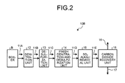
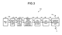
- FIGS. 2 and 3 are schematic views of another air pollution control apparatus according to the first embodiment.
- an air pollution control apparatus 10A has a denitration unit 12 that removes nitrogen oxides from a flue gas 11A containing nitrogen oxides, sulfur oxides, and carbon dioxide, for example, discharged from a boiler B up to an extremely low concentration, a desulfurization unit 13 that is installed on a gas flow downstream side of the denitration unit 12 and removes the sulfur oxides in a flue gas 11B up to an extremely low concentration, a finish denitration and desulfurization unit 14 that is installed on the gas flow downstream side of the desulfurization unit 13 and performs finish denitration and desulfurization of NO 2 having the extremely low concentration and SO 2 having the extremely low concentration remaining in a flue gas 11C by an absorbent containing sulfite, and a carbon dioxide recovery unit 15 that is installed on the gas flow downstream side of the finish denitration and desulfurization unit 14, and removes and recovers carbon dioxide in a flue gas 11D.
- a denitration unit 12 that removes nitrogen oxides from a flue gas
- NO 2 in the flue gas 11A is denitrified up to an extremely low concentration (for example, 1 ppm or less) by the generally installed denitration unit 12.
- an ammonia denitration unit can be adopted as an example.
- the SO 2 concentration in the flue gas 11B after denitration is desulfurized up to an extremely low concentration (for example, 50 ppm or less).
- an extremely low concentration for example, 50 ppm or less.
- the desulfurization unit 13 it is possible to adopt a desulfurization unit of a wet limestone and gypsum method as an example.
- the NO 2 concentration and the SO 2 concentration in the flue gas 11C is finish-removed to an extremely low concentration (0.1 ppm or less), using the absorbent containing the sulfite.
- the frequency of the cleaning operation can be reduced by about half.
- the SO 2 concentration is 1 ppm
- the SO 2 concentration is 0.1 ppm
- FIG. 5 is a graph illustrating a relation between pH and NO 2 absorptivity when the sulfite concentration in the absorbent is changed.
- FIG. 6 is a graph illustrating a relation between pH and the SO 2 equilibrium absorptivity when the sulfite concentration in the absorbent is changed.
- the standard sulfite concentration is 63 mmol/L.
- the standard sulfite concentration in the drawings is a sulfite concentration corresponding to a case where SO 2 absorbed by effluent of 5.5 t/hr from the finish denitration and desulfurization cooling tower is not oxidized at all, when the SO 2 concentration is 14 ppm in a case where an amount of the inlet flue gas is, for example, 700,000 Nm 3 /hr.
- pH and sulfite concentration is set.
- pH of the finish denitration and desulfurization unit 14 be pH 5.5 or higher, and preferably, be in a range of 5.5 to 7.0.
- a SO 2 alkali removal unit 18 may be separately installed to remove remaining SO 2 therein to be a target SO 2 concentration of 0.1 ppm or less.
- alkali treatment agent it is possible to use, for example, sodium hydroxide (NaOH) or the like.
- the sulfite concentration may be reduced to improve the desulfurization performance.
- a gas cooling unit 19 may be installed on the gas flow downstream side of the SO 2 alkali removal unit 18.
- the concentration of NO 2 and SO 2 in a flue gas 11F introduced into the carbon dioxide recovery unit 15 can be set to 0.1 ppm or less, and it is possible to suppress the accumulation of the substance caused by NO 2 and SO 2 to the CO 2 absorbent.
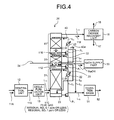
- FIG. 4 is a schematic view of an air pollution control apparatus according to a second embodiment.
- the same components as in the first embodiment are denoted by the same reference numerals, and a detailed description thereof will not be provided.
- the finish denitration and desulfurization unit 14, the SO 2 alkali removal unit 18 installed above the gas flow downstream side thereof, and the gas cooling unit 19 installed above the downstream side of the SO 2 alkali removal unit 18 are integrally disposed within a finish denitration and desulfurization cooling tower 20.
- the finish denitration and desulfurization cooling tower 20 includes a SO 2 and NO 2 absorption part 21, a SO 2 alkali removal unit 31, and a cooling water washing part 41.
- a gas introduction line L 11 that introduces the flue gas 11C after the desulfurization treatment is provided in the bottom, and a gas discharge line L 12 that sends the flue gas 11F after the advanced denitration and desulfurization cooling treatment to the carbon dioxide recovery unit 15 from the tower top part is connected thereto.
- the SO 2 and NO 2 absorption part 21 performs a denitration and desulfurization by bringing the flue gas 11C into contact with an absorbent 23 containing the sulfite circulated by a circulation line L 1 , when introducing the introduced flue gas 11C upward from the bottom.
- a circulation pump P 1 and a cooling heat exchanger 22 are disposed in the circulation line L 1 .
- the flue gas 11D subjected to denitration and desulfurization is introduced into the SO 2 alkali removal unit 31, and when introducing the introduced flue gas 11D upward, desulfurization is performed by bringing the flue gas D into contact with an alkali absorbent 32 circulated by a circulation line L 2 .
- a circulation pump P 2 is disposed in the circulation line L 2 .
- An alkaline agent (NaOH) is supplied from a NaOH supply part 33.
- the desulfurization performance may be improved by supplying an air 34 as needed.
- a part of the alkali absorbent 32 is introduced into the SO 2 and NO 2 absorption part 21 by a branch line L 4 , and the desulfurization performance may be improved by supplying the alkaline agent to the absorbent 23 containing the sulfite.
- the desulfurized flue gas 11E is introduced into the cooling water washing part 41 again, and when introducing the introduced flue gas 11E upward, cleaning and cooling is performed by bringing the flue gas 11E into contact with a cooling water 43 circulated by a circulation line L 3 .
- a circulation pump P 3 and a cooling heat exchanger 42 are disposed in the circulation line L 3 .
- a known oxidation basin 51 is disposed in the effluent treatment line L 13 , and the oxidation treatment is accelerated here.
- an effluent 52 can be applied to, for example, the treating water of a limestonegypsum method or the like.
- a gas cooling part demister is installed on the outlet side of the finish denitration and desulfurization cooling tower 20 to prevent entrainment of mist accompanied in the gas.
- the flue gas 11C after the denitration and desulfurization treatment is introduced into the SO 2 and NO 2 absorption part 21 from the gas introduction line L 11 .
- the flue gas 11C comes into contact with the circulating absorbent 23 containing the sulfite, NO 2 and SO 2 in the gas are highly removed, the NO 2 concentration in the gas becomes 0.1 ppm or less, and the SO 2 concentration becomes 1.0 ppm or less.
- the flue gas 11D after the SO 2 and NO 2 absorption treatment is introduced into the SO 2 alkali removal unit 31 on the upper side thereof.
- SO 2 in the gas is highly removed, the NO 2 concentration in the gas becomes 0.1 ppm or less, and the SO 2 concentration becomes 0.1 ppm or less.
- the flue gas 11E after the SO 2 alkali removal treatment is introduced into the cooling water washing part 41 on the upper side thereof.
- the flue gas 11E comes into contact with the circulating cooling water 43, the alkali absorbent accompanied in the gas is removed, and the gas is cooled.
- the NO 2 concentration in the flue gas 11E becomes 0.1 ppm or less, and the SO 2 concentration becomes 0.1 ppm or less.
- Example 1 in the case of providing the finish denitration and desulfurization unit 14, NO 2 and SO 2 in the gas were highly removed, the NO 2 concentration in the gas became 0.1 ppm or less, and the SO 2 concentration became 1.0 ppm or less.
- the SO 2 accumulation ratio to the absorbent of the carbon dioxide recovery unit 15 at this time was 1. Furthermore, the NO 2 accumulation ratio to the absorbent of the carbon dioxide recovery unit 15 was 0.1. Furthermore, the amine quantity ratio accompanied in the purified gas 16 discharged from the carbon dioxide recovery unit 15 was 0.3.
- Example 2 in the case of providing the finish denitration and desulfurization unit 14 and the SO 2 alkali removal unit 18, NO 2 and SO 2 in the gas were highly removed, the NO 2 concentration in the gas became 0.1 ppm or less, and the SO 2 concentration became 0.1 ppm or less.
- the SO 2 accumulation ratio to the absorbent of the carbon dioxide recovery unit 15 at this time was 0.1. Furthermore, the NO 2 accumulation ratio to the absorbent of the carbon dioxide recovery unit 15 was 0.1. Furthermore, the amine quantity ratio accompanied in the purified gas 16 discharged from the carbon dioxide recovery unit 15 was 0.3.
- Example 2 since the SO 2 alkali removal unit 18 is further provided in Example 1, the SO 2 concentration was 1/10 (0.1 ppm or less) of Example 1, and the SO 2 accumulation ratio to the absorbent of the carbon dioxide recovery unit 15 was also 1/10 (0.1 ppm or less) of Example 1.
Landscapes
- Engineering & Computer Science (AREA)
- Chemical & Material Sciences (AREA)
- Environmental & Geological Engineering (AREA)
- Health & Medical Sciences (AREA)
- Biomedical Technology (AREA)
- Analytical Chemistry (AREA)
- General Chemical & Material Sciences (AREA)
- Oil, Petroleum & Natural Gas (AREA)
- Chemical Kinetics & Catalysis (AREA)
- Treating Waste Gases (AREA)
Abstract
Description
- The present invention relates to an air pollution control apparatus in which degradation of a CO2 absorbent is suppressed in a pre-treatment that recovers and removes CO2 in a flue gas.
- As one of causes of a global warming phenomenon, for example, a greenhouse effect due to CO2 contained in the flue gas from a boiler has been pointed out, and countermeasures thereof have also become an internationally urgent need in protecting the global environment. A source of generation of CO2 extends to the various fields of activities where fossil fuel is combusted, and a demand to suppressing the discharge tends to be further strengthened. Along with this, directed at a power generation apparatus such as a thermal power plant that uses a large amount of fossil fuel, a method of removing and recovering CO2 in a flue gas by bringing the flue gas of a boiler into contact with an amine-based absorbent has been extensively studied.
- Since a CO2 absorbent that absorbs CO2 is an amine compound, the degradation and shortening of life of the absorbent due to accumulation of a substance caused by NO2 and SO2 in the flue gas have become a problem.
- For that reason, conventionally, there has been a suggestion for reducing a SO2 concentration in the flue gas from a coal combustion boiler and reducing a NO2 concentration in a natural gas flue gas (
Patent Literatures 1 and 2). -
- Patent Literature 1: Japanese Laid-open Patent Publication No.
2005-87828 - Patent Literature 2: Japanese Laid-open Patent Publication No.
2005-40683 - However, in the suggestions of
Patent Literatures 1 and 2, there is a suggestion of performing an advanced desulfurization such that a sulfur oxide concentration becomes 1 ppm, but further reduction (for example, 0.1 ppm or less) in the SO2 concentration has been required in recent years. - Similarly, in the suggestion of Patent Literature 2, there is a suggestion for performing an advanced denitration such that the nitrogen dioxide concentration becomes 3 ppm, but a further reduction (for example, preferably, 0.2 ppm or less at the outlet) in the NO2 concentration has been required in recent years.
- In view of the above-described problems, an object of the present invention is to provide an air pollution control apparatus that is capable of significantly suppressing the degradation of the CO2 absorbent in the pre-treatment that recovers and removes CO2 in the flue gas.
- According to a first aspect of the present invention in order to solve the above-mentioned problems, there is an air pollution control apparatus including: a denitration unit that removes nitrogen oxides from a flue gas up to an extremely low concentration, the flue gas being discharged from a boiler and containing nitrogen oxides, sulfur oxides, and carbon dioxide; a desulfurization unit that is installed on a gas flow downstream side of the denitration unit to remove the sulfur oxides in the flue gas up to an extremely low concentration; a finish denitration and desulfurization unit that is installed on the gas flow downstream side of the desulfurization unit to perform finish denitration and desulfurization of NO2 having an extremely low concentration and SO2 having an extremely low concentration remaining in the flue gas by an absorbent containing sulfite; and a carbon dioxide recovery unit that is installed on the gas flow downstream side of the finish denitration and desulfurization unit to remove and recover the carbon dioxide in the flue gas.
- According to a second aspect of the present invention, there is provided the air pollution control apparatus according to the first aspect, further including: a SO2 alkali removal unit that is installed on the gas flow downstream side of the finish denitration and desulfurization unit to remove residual SO2 in the flue gas by alkali.
- According to a third aspect of the present invention, there is provided the air pollution control apparatus according to the second aspect, further including: a gas cooling unit that is installed on the gas flow downstream side of the SO2 alkali removal unit to cool the flue gas.
- According to a fourth aspect of the present invention, there is provided the air pollution control apparatus according to the second aspect, wherein the finish denitration and desulfurization unit and the SO2 alkali removal unit installed above the gas flow downstream side are integrally disposed in a tower.
- According to a fifth aspect of the present invention, there is provided the air pollution control apparatus according to the fourth aspect, wherein the gas cooling unit is disposed above the downstream side of the SO2 alkali removal unit.
- According to a sixth aspect of the present invention, there is provided the air pollution control apparatus according to any one of the second to fifth aspects, wherein an oxidizing agent is introduced into the SO2 alkali removal unit.
- According to a sixth aspect of the present invention, there is provided the air pollution control apparatus according to any one of the second to sixth aspects, wherein excessive water of the SO2 alkali removal unit is introduced into the finish denitration and desulfurization unit.
- According to a seventh aspect of the present invention, there is provided the air pollution control apparatus according to any one of the second to seventh, wherein excessive water of the gas cooling unit is introduced into the SO2 alkali removal unit.
- According to the air pollution control apparatus of the present invention, it is possible to further remove NO2 having an extremely low concentration (for example, 1 ppm or less) and SO2 having an extremely low concentration (for example, 50 ppm or less) remaining in the flue gas, using an absorbent containing the sulfite, and to perform finish denitration and desulfurization up to 0.1 ppm or less. This enables the accumulation of degradation inhibitory substances of the absorbent to be suppressed, thereby suppressing a decline in the absorption performance, and maintaining the durability of the absorption capacity.
-
-
FIG. 1 is a schematic view of an air pollution control apparatus according to a first embodiment. -
FIG. 2 is a schematic view of another air pollution control apparatus according to the first embodiment. -
FIG. 3 is a schematic view of another air pollution control apparatus according to the first embodiment. -
FIG. 4 is a schematic view of an air pollution control apparatus according to a second embodiment. -
FIG. 5 is a graph illustrating a relation between pH and NO2 absorptivity when changing a sulfite concentration in the absorbent. -
FIG. 6 is a graph illustrating a relation between pH and SO2 equilibrium absorptivity when changing the sulfite concentration of the absorbent. - Preferred embodiments of an air pollution control apparatus according to the present invention will be described in detail with reference to the accompanying drawings. In addition, the present invention is not intended to be limited by these embodiments, and when there is a plurality of embodiments, an embodiment configured by combining each embodiment is also included.
-
FIG. 1 is a schematic view of an air pollution control apparatus according to a first embodiment.FIGS. 2 and3 are schematic views of another air pollution control apparatus according to the first embodiment. - As illustrated in
FIG. 1 , an airpollution control apparatus 10A according to the present embodiment has adenitration unit 12 that removes nitrogen oxides from aflue gas 11A containing nitrogen oxides, sulfur oxides, and carbon dioxide, for example, discharged from a boiler B up to an extremely low concentration, adesulfurization unit 13 that is installed on a gas flow downstream side of thedenitration unit 12 and removes the sulfur oxides in aflue gas 11B up to an extremely low concentration, a finish denitration anddesulfurization unit 14 that is installed on the gas flow downstream side of thedesulfurization unit 13 and performs finish denitration and desulfurization of NO2 having the extremely low concentration and SO2 having the extremely low concentration remaining in aflue gas 11C by an absorbent containing sulfite, and a carbondioxide recovery unit 15 that is installed on the gas flow downstream side of the finish denitration anddesulfurization unit 14, and removes and recovers carbon dioxide in aflue gas 11D. InFIG. 1 ,reference numeral 16 represents a purified gas, andreference numeral 17 represents recovery CO2. - In this embodiment, NO2 in the
flue gas 11A is denitrified up to an extremely low concentration (for example, 1 ppm or less) by the generally installeddenitration unit 12. As thedenitration unit 12, an ammonia denitration unit can be adopted as an example. - In addition, in the
desulfurization unit 13, the SO2 concentration in theflue gas 11B after denitration is desulfurized up to an extremely low concentration (for example, 50 ppm or less). In this embodiment, as thedesulfurization unit 13, it is possible to adopt a desulfurization unit of a wet limestone and gypsum method as an example. - In the present invention, the NO2 concentration and the SO2 concentration in the
flue gas 11C is finish-removed to an extremely low concentration (0.1 ppm or less), using the absorbent containing the sulfite. - In particular, by performing the finish removal of the SO2 concentration up to the extremely low concentration (0.1 ppm or less), it is possible to suppress the performance degradation of the absorbent used in the carbon
dioxide recovery unit 15. - Furthermore, it is possible to reduce the number of times of frequency of a cleaning operation (a washing operation) of the absorbent as an operation of preventing the degradation of the absorbent compared to the related art. For example, the frequency of the cleaning operation can be reduced by about half. When the SO2 concentration is 1 ppm, there was a need to perform a washing operation once every 40 days, but when the SO2 concentration is 0.1 ppm, the washing operation performed once every 80 days is sufficient.
- In this embodiment, since, as the absorbent containing the sulfite used in the finish denitration and
desulfurization unit 14, SO2 contained in theflue gas 11C is used, there is no need to separately supply a medication from the outside. When sulfite in the finish denitration and desulfurization unit is insufficient, it is possible to cope with insufficiency by increasing the SO2 concentration of the outlet of the desulfurization unit. -
FIG. 5 is a graph illustrating a relation between pH and NO2 absorptivity when the sulfite concentration in the absorbent is changed.FIG. 6 is a graph illustrating a relation between pH and the SO2 equilibrium absorptivity when the sulfite concentration in the absorbent is changed. - Here, the standard sulfite concentration is 63 mmol/L. The standard sulfite concentration in the drawings is a sulfite concentration corresponding to a case where SO2 absorbed by effluent of 5.5 t/hr from the finish denitration and desulfurization cooling tower is not oxidized at all, when the SO2 concentration is 14 ppm in a case where an amount of the inlet flue gas is, for example, 700,000 Nm3/hr.
- As illustrated in
FIGS. 5 and 6 , the higher the sulfite concentration is, the better the removal efficiency of NO2 is, but the removal efficiency of SO2 declines. - Therefore, in order to achieve the extremely low concentration of the NO2 and SO2 concentration remaining in the flue gas, pH and sulfite concentration is set.
- In this embodiment, it is preferred that pH of the finish denitration and
desulfurization unit 14 be pH 5.5 or higher, and preferably, be in a range of 5.5 to 7.0. - Furthermore, when placing emphasis on the NO2 removal in the flue gas, at the expense of the removal of SO2 at the finish denitration and
desulfurization unit 14, as in an airpollution control apparatus 10B illustrated inFIG. 2 , on the gas flow downstream side of the finish denitration anddesulfurization unit 14, a SO2alkali removal unit 18 may be separately installed to remove remaining SO2 therein to be a target SO2 concentration of 0.1 ppm or less. - In this case, as the alkali treatment agent, it is possible to use, for example, sodium hydroxide (NaOH) or the like.
- Here, by supplying air into the SO2
alkali removal unit 18 to perform the air oxidation, the sulfite concentration may be reduced to improve the desulfurization performance. - Furthermore, in order to prevent the entrainment of the alkali treatment agent to the carbon
dioxide recovery unit 15 side and perform cooling of aflue gas 11E, as in an airpollution control apparatus 10C illustrated inFIG. 3 , a gas cooling unit 19 may be installed on the gas flow downstream side of the SO2alkali removal unit 18. - Thus, by performing the desulfurization and denitration by the finish denitration and
desulfurization unit 14 including the sulfite, and by separately disposing the advanced desulfurization by the absorbent added with the alkali treatment agent (NaOH), it is possible to maintain the NO2 removal performance and further to prevent a decrease in SO2 removal performance, the concentration of NO2 and SO2 in aflue gas 11F introduced into the carbondioxide recovery unit 15 can be set to 0.1 ppm or less, and it is possible to suppress the accumulation of the substance caused by NO2 and SO2 to the CO2 absorbent. - An air pollution control apparatus according to an embodiment of the present invention will be described with reference to the drawings.
FIG. 4 is a schematic view of an air pollution control apparatus according to a second embodiment. In addition, the same components as in the first embodiment are denoted by the same reference numerals, and a detailed description thereof will not be provided. - In the air pollution control apparatus according to the present embodiment, the finish denitration and
desulfurization unit 14, the SO2alkali removal unit 18 installed above the gas flow downstream side thereof, and the gas cooling unit 19 installed above the downstream side of the SO2alkali removal unit 18 are integrally disposed within a finish denitration anddesulfurization cooling tower 20. - As illustrated in
FIG. 4 , in the order from the bottom of the tower, the finish denitration anddesulfurization cooling tower 20 includes a SO2 and NO2absorption part 21, a SO2 alkali removal unit 31, and a cooling water washing part 41. - In the SO2 and NO2
absorption part 21 of the bottom side of the finish denitration anddesulfurization cooling tower 20, a gas introduction line L11 that introduces theflue gas 11C after the desulfurization treatment is provided in the bottom, and a gas discharge line L12 that sends theflue gas 11F after the advanced denitration and desulfurization cooling treatment to the carbondioxide recovery unit 15 from the tower top part is connected thereto. - The SO2 and NO2
absorption part 21 performs a denitration and desulfurization by bringing theflue gas 11C into contact with an absorbent 23 containing the sulfite circulated by a circulation line L1, when introducing the introducedflue gas 11C upward from the bottom. A circulation pump P1 and acooling heat exchanger 22 are disposed in the circulation line L1. - In the SO2 and NO2
absorption part 21, theflue gas 11D subjected to denitration and desulfurization is introduced into the SO2 alkali removal unit 31, and when introducing the introducedflue gas 11D upward, desulfurization is performed by bringing the flue gas D into contact with an alkali absorbent 32 circulated by a circulation line L2. A circulation pump P2 is disposed in the circulation line L2. An alkaline agent (NaOH) is supplied from aNaOH supply part 33. Furthermore, the desulfurization performance may be improved by supplying anair 34 as needed. - In addition, a part of the
alkali absorbent 32 is introduced into the SO2 and NO2absorption part 21 by a branch line L4, and the desulfurization performance may be improved by supplying the alkaline agent to the absorbent 23 containing the sulfite. - In the SO2 alkali removal unit 31, the desulfurized
flue gas 11E is introduced into the cooling water washing part 41 again, and when introducing the introducedflue gas 11E upward, cleaning and cooling is performed by bringing theflue gas 11E into contact with a coolingwater 43 circulated by a circulation line L3. A circulation pump P3 and acooling heat exchanger 42 are disposed in the circulation line L3. - In addition, since the sulfite in the solution is diluted by supplying an
excessive water 43a of the coolingwater 43 to the SO2 alkali removal unit 31 via an excessive water supply line L5, the desulfurization performance is improved. - Furthermore, a part of the
excessive water 43a is discharged to an effluent treatment line L13 via an effluent line L6. - A known
oxidation basin 51 is disposed in the effluent treatment line L13, and the oxidation treatment is accelerated here. In addition, aneffluent 52 can be applied to, for example, the treating water of a limestonegypsum method or the like. - Furthermore, on the outlet side of the finish denitration and
desulfurization cooling tower 20, a gas cooling part demister is installed to prevent entrainment of mist accompanied in the gas. - According to such a configuration, when the NO2 concentration in the
flue gas 11A discharged from the boiler B is approximately 6 to 15 ppm, and the SO2 concentration is approximately 300 to 1,000 ppm, by passing through thedenitration unit 12 thedesulfurization unit 13, the NO2 concentration in theflue gas 11C becomes approximately 0.5 to 2 ppm, and the SO2 concentration becomes approximately 15 to 50 ppm. - Moreover, the
flue gas 11C after the denitration and desulfurization treatment is introduced into the SO2 and NO2absorption part 21 from the gas introduction line L11. When theflue gas 11C comes into contact with the circulating absorbent 23 containing the sulfite, NO2 and SO2 in the gas are highly removed, the NO2 concentration in the gas becomes 0.1 ppm or less, and the SO2 concentration becomes 1.0 ppm or less. - Next, the
flue gas 11D after the SO2 and NO2 absorption treatment is introduced into the SO2 alkali removal unit 31 on the upper side thereof. When theflue gas 11D comes into contact with the circulating alkali absorbent 32, SO2 in the gas is highly removed, the NO2 concentration in the gas becomes 0.1 ppm or less, and the SO2 concentration becomes 0.1 ppm or less. - Next, the
flue gas 11E after the SO2 alkali removal treatment is introduced into the cooling water washing part 41 on the upper side thereof. When theflue gas 11E comes into contact with the circulatingcooling water 43, the alkali absorbent accompanied in the gas is removed, and the gas is cooled. The NO2 concentration in theflue gas 11E becomes 0.1 ppm or less, and the SO2 concentration becomes 0.1 ppm or less. - Hereinafter, the effects of the present invention will be specifically described by Examples, but the present invention is not limited thereto.
- As in the air
pollution control apparatus 10A illustrated inFIG. 1 , when the finish denitration anddesulfurization unit 14 is provided between thedesulfurization unit 13 and the carbondioxide recovery unit 15, a SO2 accumulation ratio and a NO2 accumulation ratio to the absorbent of the carbondioxide recovery unit 15 were determined. Furthermore, an amine quantity ratio accompanied in the purifiedgas 16 discharged from the carbondioxide recovery unit 15 was obtained. - As in the air
pollution control apparatus 10B illustrated inFIG. 2 , when the finish denitration anddesulfurization unit 14 and the SO2alkali removal unit 18 are provided between thedesulfurization unit 13 and the carbondioxide recovery unit 15, a SO2 accumulation ratio and a NO2 accumulation ratio to the absorbent of the carbondioxide recovery unit 15 were determined. Furthermore, an amine quantity ratio accompanied in the purifiedgas 16 discharged from the carbondioxide recovery unit 15 was obtained. - As in the air pollution control apparatus of the related art, when the finish denitration and
desulfurization unit 14 and the SO2alkali removal unit 18 are not provided, and the carbondioxide recovery unit 15 is directly installed on the downstream side of thedesulfurization unit 13, a SO2 accumulation ratio and a NO2 accumulation ratio to the absorbent of the carbondioxide recovery unit 15 were determined. Furthermore, an amine quantity ratio accompanied in the purifiedgas 16 discharged from the carbondioxide recovery unit 15 was obtained. - The results are illustrated in Table 1.
Table 1 Example 1 Example 2 Comparative Example 1 Gas temperature of CO2 recovery unit inlet (°C) 40 40 52 SO2 concentration of CO2 recovery unit inlet (ppm) 1 or less 0.1 or less 5 SO2 accumulation ratio to absorbent of CO2 recovery unit (-) 1 0.1 1
(standard)Amine quantity ratio accompanied in CO2 recovery unit outlet gas (-) 0.3 0.3 1 (standard) NO2 concentration of CO2 recovery unit inlet (ppm) 0.1 or less 0.1 or less 1 NO2 accumulation ratio to absorbent of CO2 recovery unit (-) 0.1 0.1 1 (standard) Finish denitration and desulfurization unit 14Presence Presence Absence SO2 alkali removal unit 18Absence Presence Absence - As illustrated in Table 1, in Example 1, in the case of providing the finish denitration and
desulfurization unit 14, NO2 and SO2 in the gas were highly removed, the NO2 concentration in the gas became 0.1 ppm or less, and the SO2 concentration became 1.0 ppm or less. - The SO2 accumulation ratio to the absorbent of the carbon
dioxide recovery unit 15 at this time was 1. Furthermore, the NO2 accumulation ratio to the absorbent of the carbondioxide recovery unit 15 was 0.1. Furthermore, the amine quantity ratio accompanied in the purifiedgas 16 discharged from the carbondioxide recovery unit 15 was 0.3. - Furthermore, in Example 2, in the case of providing the finish denitration and
desulfurization unit 14 and the SO2alkali removal unit 18, NO2 and SO2 in the gas were highly removed, the NO2 concentration in the gas became 0.1 ppm or less, and the SO2 concentration became 0.1 ppm or less. - The SO2 accumulation ratio to the absorbent of the carbon
dioxide recovery unit 15 at this time was 0.1. Furthermore, the NO2 accumulation ratio to the absorbent of the carbondioxide recovery unit 15 was 0.1. Furthermore, the amine quantity ratio accompanied in the purifiedgas 16 discharged from the carbondioxide recovery unit 15 was 0.3. - In Example 2, since the SO2
alkali removal unit 18 is further provided in Example 1, the SO2 concentration was 1/10 (0.1 ppm or less) of Example 1, and the SO2 accumulation ratio to the absorbent of the carbondioxide recovery unit 15 was also 1/10 (0.1 ppm or less) of Example 1. -
- 10A to 10C AIR POLLUTION CONTROL APPARATUS
- 11A to 11F FLUE GAS
- 12 DENITRATION UNIT
- 13 DESULFURIZATION UNIT
- 14 FINISH DENITRATION AND DESULFURIZATION UNIT
- 15 CARBON DIOXIDE RECOVERY UNIT
Claims (8)
- An air pollution control apparatus comprising:a denitration unit that removes nitrogen oxides from a flue gas up to an extremely low concentration, the flue gas being discharged from a boiler and containing nitrogen oxides, sulfur oxides, and carbon dioxide;a desulfurization unit that is installed on a gas flow downstream side of the denitration unit to remove the sulfur oxides in the flue gas up to an extremely low concentration;a finish denitration and desulfurization unit that is installed on the gas flow downstream side of the desulfurization unit to perform finish denitration and desulfurization of NO2 having an extremely low concentration and SO2 having an extremely low concentration remaining in the flue gas by an absorbent containing sulfite; anda carbon dioxide recovery unit that is installed on the gas flow downstream side of the finish denitration and desulfurization unit to remove and recover the carbon dioxide in the flue gas.
- The air pollution control apparatus according to claim 1, further comprising:a SO2 alkali removal unit that is installed on the gas flow downstream side of the finish denitration and desulfurization unit to remove residual SO2 in the flue gas by alkali.
- The air pollution control apparatus according to claim 2, further comprising:a gas cooling unit that is installed on the gas flow downstream side of the SO2 alkali removal unit to cool the flue gas.
- The air pollution control apparatus according to claim 2, wherein the finish denitration and desulfurization unit and the SO2 alkali removal unit installed above the gas flow downstream side are integrally disposed in a tower.
- The air pollution control apparatus according to claim 4, wherein the gas cooling unit is disposed above the downstream side of the SO2 alkali removal unit.
- The air pollution control apparatus according to any one of claims 2 to 5, wherein an oxidizing agent is introduced into the SO2 alkali removal unit.
- The air pollution control apparatus according to any one of claims 2 to 6, wherein excessive water of the SO2 alkali removal unit is introduced into the finish denitration and desulfurization unit.
- The air pollution control apparatus according to any one of claims 2 to 7, wherein excessive water of the gas cooling unit is introduced into the SO2 alkali removal unit.
Applications Claiming Priority (2)
| Application Number | Priority Date | Filing Date | Title |
|---|---|---|---|
| JP2012119786A JP6057545B2 (en) | 2012-05-25 | 2012-05-25 | Exhaust gas treatment equipment |
| PCT/JP2013/063828 WO2013176060A1 (en) | 2012-05-25 | 2013-05-17 | Discharge gas treatment device |
Publications (3)
| Publication Number | Publication Date |
|---|---|
| EP2859936A1 true EP2859936A1 (en) | 2015-04-15 |
| EP2859936A4 EP2859936A4 (en) | 2016-03-09 |
| EP2859936B1 EP2859936B1 (en) | 2021-08-25 |
Family
ID=49623754
Family Applications (1)
| Application Number | Title | Priority Date | Filing Date |
|---|---|---|---|
| EP13793951.8A Active EP2859936B1 (en) | 2012-05-25 | 2013-05-17 | Air pollution control apparatus and method |
Country Status (6)
| Country | Link |
|---|---|
| US (1) | US9789438B2 (en) |
| EP (1) | EP2859936B1 (en) |
| JP (1) | JP6057545B2 (en) |
| AU (1) | AU2013264029B2 (en) |
| CA (1) | CA2877611C (en) |
| WO (1) | WO2013176060A1 (en) |
Cited By (4)
| Publication number | Priority date | Publication date | Assignee | Title |
|---|---|---|---|---|
| CN105169917A (en) * | 2015-09-26 | 2015-12-23 | 国网河南省电力公司电力科学研究院 | SNCR-SCR combined denitration system and method based on ammonia nitrogen molar ratio detection and regulation |
| CN105879643A (en) * | 2016-05-28 | 2016-08-24 | 东莞市联洲知识产权运营管理有限公司 | Novel magnesium-method flue gas desulphurization method |
| CN109126457A (en) * | 2018-09-07 | 2019-01-04 | 南通航泰船舶机械有限公司 | A kind of marine internal combustion engine tail gas desulfurization method of denitration |
| CN111450674A (en) * | 2020-04-23 | 2020-07-28 | 自贡市东方联合机械配套有限公司 | Tail gas reoxidation device for removing acidic oxide smoke exhaust pipeline |
Families Citing this family (9)
| Publication number | Priority date | Publication date | Assignee | Title |
|---|---|---|---|---|
| CN105561769B (en) * | 2014-10-17 | 2019-05-21 | 华东理工大学 | Denitrification device and method for oxidizing NO with salt-enhanced hydrogen peroxide solution |
| CN107648965A (en) * | 2016-07-25 | 2018-02-02 | 庄建中 | The smoke comprehensive purifying technique and equipment of a kind of combustion refuse |
| CN106178893A (en) * | 2016-08-25 | 2016-12-07 | 上海甘澍环境科技有限公司 | A kind of alkali liquor absorption tower and use its method that flue gas is carried out wet denitration |
| JP6634395B2 (en) | 2017-01-24 | 2020-01-22 | 三菱重工エンジニアリング株式会社 | Exhaust gas treatment device and CO2 recovery device using the same |
| GB2554776B (en) * | 2017-03-13 | 2020-05-27 | Rocco Tulino Rosario | Particular liquid solution suitable to cool down and catch the pollutants that are inside the exhausts of diesel engines |
| CN109173637A (en) * | 2018-10-30 | 2019-01-11 | 攀钢集团攀枝花钢铁研究院有限公司 | The method of low-temperature flue gas liquid phase oxidation denitration |
| CN112403154A (en) * | 2019-11-05 | 2021-02-26 | 中冶长天国际工程有限责任公司 | Flue gas multi-pollutant cooperative purification process and device |
| KR102378554B1 (en) * | 2020-07-07 | 2022-03-24 | 한국조선해양 주식회사 | Exhaust gas treatment apparatus for ship and ship having the same |
| CN117398835A (en) * | 2023-10-13 | 2024-01-16 | 首钢京唐钢铁联合有限责任公司 | Flue gas denitration control methods and related equipment for heating furnaces |
Family Cites Families (12)
| Publication number | Priority date | Publication date | Assignee | Title |
|---|---|---|---|---|
| JPS5284171A (en) * | 1977-02-08 | 1977-07-13 | Showa Denko Kk | Removal of nitrogen oxides and sulfur oxides in gas |
| WO1985003238A2 (en) | 1984-01-25 | 1985-08-01 | Hoelter Heinz | Process for stripping nitrogen oxides and sulphur oxides as well as optionally other noxious elements of flue gas from combustion plants |
| JPH03293017A (en) * | 1990-04-11 | 1991-12-24 | Mitsubishi Heavy Ind Ltd | Treatment of waste combustion gas |
| JP3305001B2 (en) * | 1992-03-03 | 2002-07-22 | 関西電力株式会社 | Method for removing carbon dioxide and sulfur oxides from flue gas |
| US7628967B2 (en) * | 2002-10-01 | 2009-12-08 | Airborne Industrial Minerals, Inc. | Removal of Hg, NOx, and SOx with using oxidants and staged gas/liquid contact |
| JP4838489B2 (en) * | 2003-07-25 | 2011-12-14 | 関西電力株式会社 | Method and apparatus for removing nitrogen dioxide and carbon dioxide |
| JP4216152B2 (en) * | 2003-09-16 | 2009-01-28 | 関西電力株式会社 | Desulfurization decarboxylation method and apparatus |
| US20090013868A1 (en) * | 2007-07-11 | 2009-01-15 | Arthur Darde | Process and apparatus for the separation of a gaseous mixture |
| US20110014106A1 (en) * | 2009-07-15 | 2011-01-20 | Fmc Corporation | COMBUSTION FLUE GAS SOx TREATMENT VIA DRY SORBENT INJECTION |
| CA2801008C (en) * | 2010-05-31 | 2015-12-08 | Mitsubishi Heavy Industries, Ltd. | Air pollution control system and method |
| JPWO2011152551A1 (en) | 2010-05-31 | 2013-08-01 | 三菱重工業株式会社 | Exhaust gas treatment system and method |
| KR101266258B1 (en) | 2011-01-28 | 2013-05-22 | 한국에너지기술연구원 | A fuel gas treatment apparatus for Carbon dioxide capture process and the method |
-
2012
- 2012-05-25 JP JP2012119786A patent/JP6057545B2/en active Active
-
2013
- 2013-05-17 AU AU2013264029A patent/AU2013264029B2/en active Active
- 2013-05-17 US US14/403,734 patent/US9789438B2/en active Active
- 2013-05-17 EP EP13793951.8A patent/EP2859936B1/en active Active
- 2013-05-17 CA CA2877611A patent/CA2877611C/en active Active
- 2013-05-17 WO PCT/JP2013/063828 patent/WO2013176060A1/en not_active Ceased
Cited By (5)
| Publication number | Priority date | Publication date | Assignee | Title |
|---|---|---|---|---|
| CN105169917A (en) * | 2015-09-26 | 2015-12-23 | 国网河南省电力公司电力科学研究院 | SNCR-SCR combined denitration system and method based on ammonia nitrogen molar ratio detection and regulation |
| CN105879643A (en) * | 2016-05-28 | 2016-08-24 | 东莞市联洲知识产权运营管理有限公司 | Novel magnesium-method flue gas desulphurization method |
| CN105879643B (en) * | 2016-05-28 | 2018-06-15 | 广东世纪青山镍业有限公司 | A kind of magnesium method flue gas desulphurization method |
| CN109126457A (en) * | 2018-09-07 | 2019-01-04 | 南通航泰船舶机械有限公司 | A kind of marine internal combustion engine tail gas desulfurization method of denitration |
| CN111450674A (en) * | 2020-04-23 | 2020-07-28 | 自贡市东方联合机械配套有限公司 | Tail gas reoxidation device for removing acidic oxide smoke exhaust pipeline |
Also Published As
| Publication number | Publication date |
|---|---|
| US9789438B2 (en) | 2017-10-17 |
| US20150125353A1 (en) | 2015-05-07 |
| WO2013176060A1 (en) | 2013-11-28 |
| EP2859936A4 (en) | 2016-03-09 |
| CA2877611A1 (en) | 2013-11-28 |
| CA2877611C (en) | 2016-12-13 |
| AU2013264029A1 (en) | 2015-01-22 |
| JP6057545B2 (en) | 2017-01-11 |
| AU2013264029B2 (en) | 2016-05-12 |
| EP2859936B1 (en) | 2021-08-25 |
| JP2013244454A (en) | 2013-12-09 |
Similar Documents
| Publication | Publication Date | Title |
|---|---|---|
| EP2859936B1 (en) | Air pollution control apparatus and method | |
| EP3685907B1 (en) | Air pollution control system and air pollution control method | |
| US9138677B2 (en) | Ammonia stripper for a carbon capture system for reduction of energy consumption | |
| US8420037B2 (en) | Air pollution control system and air pollution control method | |
| US9381461B2 (en) | Air pollution control system and method | |
| CN103221103B (en) | Treatment of contaminated amine solvents due to ingress of sulfur oxides | |
| JP4959303B2 (en) | Exhaust gas treatment method and treatment apparatus | |
| JP6634395B2 (en) | Exhaust gas treatment device and CO2 recovery device using the same | |
| US20160288049A1 (en) | Reclaiming device, method, and recovery unit of co2, h2s, or both of co2 and h2s | |
| EP2659949A1 (en) | C02 recovery system | |
| CN107551785A (en) | Sour gas retracting device and sour gas recovery method | |
| KR20210131947A (en) | Method for automatic controlling acid gas capture process | |
| JP5881498B2 (en) | Nitrogen oxide and sulfur oxide removal system, nitrogen oxide and sulfur oxide removal method, and carbon dioxide recovery system | |
| EP2659948A1 (en) | C02 recovery system | |
| KR20140056502A (en) | Method for preventing vaporization of absorbent in the co2 capture process | |
| KR20250001986A (en) | Acid gas capture system by heat exchange optimization having codensed water recovery line |
Legal Events
| Date | Code | Title | Description |
|---|---|---|---|
| PUAI | Public reference made under article 153(3) epc to a published international application that has entered the european phase |
Free format text: ORIGINAL CODE: 0009012 |
|
| 17P | Request for examination filed |
Effective date: 20141224 |
|
| AK | Designated contracting states |
Kind code of ref document: A1 Designated state(s): AL AT BE BG CH CY CZ DE DK EE ES FI FR GB GR HR HU IE IS IT LI LT LU LV MC MK MT NL NO PL PT RO RS SE SI SK SM TR |
|
| AX | Request for extension of the european patent |
Extension state: BA ME |
|
| DAX | Request for extension of the european patent (deleted) | ||
| RA4 | Supplementary search report drawn up and despatched (corrected) |
Effective date: 20160204 |
|
| RIC1 | Information provided on ipc code assigned before grant |
Ipc: B01D 53/56 20060101ALI20160129BHEP Ipc: B01D 53/75 20060101ALI20160129BHEP Ipc: B01D 53/60 20060101ALI20160129BHEP Ipc: B01D 53/77 20060101ALI20160129BHEP Ipc: B01D 53/62 20060101AFI20160129BHEP Ipc: B01D 53/74 20060101ALI20160129BHEP Ipc: B01D 53/34 20060101ALI20160129BHEP Ipc: B01D 53/50 20060101ALI20160129BHEP Ipc: B01D 53/94 20060101ALI20160129BHEP |
|
| STAA | Information on the status of an ep patent application or granted ep patent |
Free format text: STATUS: EXAMINATION IS IN PROGRESS |
|
| 17Q | First examination report despatched |
Effective date: 20180605 |
|
| RAP1 | Party data changed (applicant data changed or rights of an application transferred) |
Owner name: MITSUBISHI HEAVY INDUSTRIES ENGINEERING, LTD. |
|
| GRAP | Despatch of communication of intention to grant a patent |
Free format text: ORIGINAL CODE: EPIDOSNIGR1 |
|
| STAA | Information on the status of an ep patent application or granted ep patent |
Free format text: STATUS: GRANT OF PATENT IS INTENDED |
|
| INTG | Intention to grant announced |
Effective date: 20210315 |
|
| GRAS | Grant fee paid |
Free format text: ORIGINAL CODE: EPIDOSNIGR3 |
|
| GRAA | (expected) grant |
Free format text: ORIGINAL CODE: 0009210 |
|
| STAA | Information on the status of an ep patent application or granted ep patent |
Free format text: STATUS: THE PATENT HAS BEEN GRANTED |
|
| AK | Designated contracting states |
Kind code of ref document: B1 Designated state(s): AL AT BE BG CH CY CZ DE DK EE ES FI FR GB GR HR HU IE IS IT LI LT LU LV MC MK MT NL NO PL PT RO RS SE SI SK SM TR |
|
| REG | Reference to a national code |
Ref country code: GB Ref legal event code: FG4D |
|
| REG | Reference to a national code |
Ref country code: CH Ref legal event code: EP |
|
| REG | Reference to a national code |
Ref country code: DE Ref legal event code: R096 Ref document number: 602013078977 Country of ref document: DE |
|
| REG | Reference to a national code |
Ref country code: IE Ref legal event code: FG4D Ref country code: AT Ref legal event code: REF Ref document number: 1423219 Country of ref document: AT Kind code of ref document: T Effective date: 20210915 |
|
| REG | Reference to a national code |
Ref country code: NL Ref legal event code: FP |
|
| REG | Reference to a national code |
Ref country code: LT Ref legal event code: MG9D |
|
| REG | Reference to a national code |
Ref country code: AT Ref legal event code: MK05 Ref document number: 1423219 Country of ref document: AT Kind code of ref document: T Effective date: 20210825 |
|
| PG25 | Lapsed in a contracting state [announced via postgrant information from national office to epo] |
Ref country code: RS Free format text: LAPSE BECAUSE OF FAILURE TO SUBMIT A TRANSLATION OF THE DESCRIPTION OR TO PAY THE FEE WITHIN THE PRESCRIBED TIME-LIMIT Effective date: 20210825 Ref country code: PT Free format text: LAPSE BECAUSE OF FAILURE TO SUBMIT A TRANSLATION OF THE DESCRIPTION OR TO PAY THE FEE WITHIN THE PRESCRIBED TIME-LIMIT Effective date: 20211227 Ref country code: ES Free format text: LAPSE BECAUSE OF FAILURE TO SUBMIT A TRANSLATION OF THE DESCRIPTION OR TO PAY THE FEE WITHIN THE PRESCRIBED TIME-LIMIT Effective date: 20210825 Ref country code: FI Free format text: LAPSE BECAUSE OF FAILURE TO SUBMIT A TRANSLATION OF THE DESCRIPTION OR TO PAY THE FEE WITHIN THE PRESCRIBED TIME-LIMIT Effective date: 20210825 Ref country code: LT Free format text: LAPSE BECAUSE OF FAILURE TO SUBMIT A TRANSLATION OF THE DESCRIPTION OR TO PAY THE FEE WITHIN THE PRESCRIBED TIME-LIMIT Effective date: 20210825 Ref country code: AT Free format text: LAPSE BECAUSE OF FAILURE TO SUBMIT A TRANSLATION OF THE DESCRIPTION OR TO PAY THE FEE WITHIN THE PRESCRIBED TIME-LIMIT Effective date: 20210825 Ref country code: BG Free format text: LAPSE BECAUSE OF FAILURE TO SUBMIT A TRANSLATION OF THE DESCRIPTION OR TO PAY THE FEE WITHIN THE PRESCRIBED TIME-LIMIT Effective date: 20211125 Ref country code: HR Free format text: LAPSE BECAUSE OF FAILURE TO SUBMIT A TRANSLATION OF THE DESCRIPTION OR TO PAY THE FEE WITHIN THE PRESCRIBED TIME-LIMIT Effective date: 20210825 Ref country code: SE Free format text: LAPSE BECAUSE OF FAILURE TO SUBMIT A TRANSLATION OF THE DESCRIPTION OR TO PAY THE FEE WITHIN THE PRESCRIBED TIME-LIMIT Effective date: 20210825 |
|
| REG | Reference to a national code |
Ref country code: NO Ref legal event code: T2 Effective date: 20210825 |
|
| PG25 | Lapsed in a contracting state [announced via postgrant information from national office to epo] |
Ref country code: PL Free format text: LAPSE BECAUSE OF FAILURE TO SUBMIT A TRANSLATION OF THE DESCRIPTION OR TO PAY THE FEE WITHIN THE PRESCRIBED TIME-LIMIT Effective date: 20210825 Ref country code: LV Free format text: LAPSE BECAUSE OF FAILURE TO SUBMIT A TRANSLATION OF THE DESCRIPTION OR TO PAY THE FEE WITHIN THE PRESCRIBED TIME-LIMIT Effective date: 20210825 Ref country code: GR Free format text: LAPSE BECAUSE OF FAILURE TO SUBMIT A TRANSLATION OF THE DESCRIPTION OR TO PAY THE FEE WITHIN THE PRESCRIBED TIME-LIMIT Effective date: 20211126 |
|
| PG25 | Lapsed in a contracting state [announced via postgrant information from national office to epo] |
Ref country code: DK Free format text: LAPSE BECAUSE OF FAILURE TO SUBMIT A TRANSLATION OF THE DESCRIPTION OR TO PAY THE FEE WITHIN THE PRESCRIBED TIME-LIMIT Effective date: 20210825 |
|
| REG | Reference to a national code |
Ref country code: DE Ref legal event code: R097 Ref document number: 602013078977 Country of ref document: DE |
|
| PG25 | Lapsed in a contracting state [announced via postgrant information from national office to epo] |
Ref country code: SM Free format text: LAPSE BECAUSE OF FAILURE TO SUBMIT A TRANSLATION OF THE DESCRIPTION OR TO PAY THE FEE WITHIN THE PRESCRIBED TIME-LIMIT Effective date: 20210825 Ref country code: SK Free format text: LAPSE BECAUSE OF FAILURE TO SUBMIT A TRANSLATION OF THE DESCRIPTION OR TO PAY THE FEE WITHIN THE PRESCRIBED TIME-LIMIT Effective date: 20210825 Ref country code: RO Free format text: LAPSE BECAUSE OF FAILURE TO SUBMIT A TRANSLATION OF THE DESCRIPTION OR TO PAY THE FEE WITHIN THE PRESCRIBED TIME-LIMIT Effective date: 20210825 Ref country code: EE Free format text: LAPSE BECAUSE OF FAILURE TO SUBMIT A TRANSLATION OF THE DESCRIPTION OR TO PAY THE FEE WITHIN THE PRESCRIBED TIME-LIMIT Effective date: 20210825 Ref country code: CZ Free format text: LAPSE BECAUSE OF FAILURE TO SUBMIT A TRANSLATION OF THE DESCRIPTION OR TO PAY THE FEE WITHIN THE PRESCRIBED TIME-LIMIT Effective date: 20210825 Ref country code: AL Free format text: LAPSE BECAUSE OF FAILURE TO SUBMIT A TRANSLATION OF THE DESCRIPTION OR TO PAY THE FEE WITHIN THE PRESCRIBED TIME-LIMIT Effective date: 20210825 |
|
| PLBE | No opposition filed within time limit |
Free format text: ORIGINAL CODE: 0009261 |
|
| STAA | Information on the status of an ep patent application or granted ep patent |
Free format text: STATUS: NO OPPOSITION FILED WITHIN TIME LIMIT |
|
| 26N | No opposition filed |
Effective date: 20220527 |
|
| PG25 | Lapsed in a contracting state [announced via postgrant information from national office to epo] |
Ref country code: SI Free format text: LAPSE BECAUSE OF FAILURE TO SUBMIT A TRANSLATION OF THE DESCRIPTION OR TO PAY THE FEE WITHIN THE PRESCRIBED TIME-LIMIT Effective date: 20210825 |
|
| REG | Reference to a national code |
Ref country code: CH Ref legal event code: PL |
|
| REG | Reference to a national code |
Ref country code: BE Ref legal event code: MM Effective date: 20220531 |
|
| PG25 | Lapsed in a contracting state [announced via postgrant information from national office to epo] |
Ref country code: MC Free format text: LAPSE BECAUSE OF FAILURE TO SUBMIT A TRANSLATION OF THE DESCRIPTION OR TO PAY THE FEE WITHIN THE PRESCRIBED TIME-LIMIT Effective date: 20210825 Ref country code: LU Free format text: LAPSE BECAUSE OF NON-PAYMENT OF DUE FEES Effective date: 20220517 Ref country code: LI Free format text: LAPSE BECAUSE OF NON-PAYMENT OF DUE FEES Effective date: 20220531 Ref country code: CH Free format text: LAPSE BECAUSE OF NON-PAYMENT OF DUE FEES Effective date: 20220531 |
|
| REG | Reference to a national code |
Ref country code: FR Ref legal event code: PLFP Year of fee payment: 11 |
|
| PG25 | Lapsed in a contracting state [announced via postgrant information from national office to epo] |
Ref country code: IE Free format text: LAPSE BECAUSE OF NON-PAYMENT OF DUE FEES Effective date: 20220517 |
|
| PG25 | Lapsed in a contracting state [announced via postgrant information from national office to epo] |
Ref country code: BE Free format text: LAPSE BECAUSE OF NON-PAYMENT OF DUE FEES Effective date: 20220531 |
|
| P01 | Opt-out of the competence of the unified patent court (upc) registered |
Effective date: 20230522 |
|
| REG | Reference to a national code |
Ref country code: DE Ref legal event code: R081 Ref document number: 602013078977 Country of ref document: DE Owner name: MITSUBISHI HEAVY INDUSTRIES, LTD., JP Free format text: FORMER OWNER: MITSUBISHI HEAVY INDUSTRIES ENGINEERING, LTD., YOKOHAMA-SHI, KANAGAWA, JP |
|
| REG | Reference to a national code |
Ref country code: DE Ref legal event code: R081 Ref document number: 602013078977 Country of ref document: DE Owner name: MITSUBISHI HEAVY INDUSTRIES, LTD., JP Free format text: FORMER OWNER: MHI ENGINEERING, LTD., YOKOHAMA-SHI, KANAGAWA, JP |
|
| REG | Reference to a national code |
Ref country code: NL Ref legal event code: PD Owner name: MITSUBISHI HEAVY INDUSTRIES, LTD.; JP Free format text: DETAILS ASSIGNMENT: CHANGE OF OWNER(S), ASSIGNMENT; FORMER OWNER NAME: MHI ENGINEERING, LTD. Effective date: 20231206 Ref country code: NL Ref legal event code: HC Owner name: MHI ENGINEERING, LTD.; JP Free format text: DETAILS ASSIGNMENT: CHANGE OF OWNER(S), CHANGE OF OWNER(S) NAME; FORMER OWNER NAME: MITSUBISHI HEAVY INDUSTRIES ENGINEERING, LTD. Effective date: 20231206 |
|
| PG25 | Lapsed in a contracting state [announced via postgrant information from national office to epo] |
Ref country code: HU Free format text: LAPSE BECAUSE OF FAILURE TO SUBMIT A TRANSLATION OF THE DESCRIPTION OR TO PAY THE FEE WITHIN THE PRESCRIBED TIME-LIMIT; INVALID AB INITIO Effective date: 20130517 |
|
| PG25 | Lapsed in a contracting state [announced via postgrant information from national office to epo] |
Ref country code: MK Free format text: LAPSE BECAUSE OF FAILURE TO SUBMIT A TRANSLATION OF THE DESCRIPTION OR TO PAY THE FEE WITHIN THE PRESCRIBED TIME-LIMIT Effective date: 20210825 Ref country code: CY Free format text: LAPSE BECAUSE OF FAILURE TO SUBMIT A TRANSLATION OF THE DESCRIPTION OR TO PAY THE FEE WITHIN THE PRESCRIBED TIME-LIMIT Effective date: 20210825 |
|
| REG | Reference to a national code |
Ref country code: GB Ref legal event code: 732E Free format text: REGISTERED BETWEEN 20240404 AND 20240410 |
|
| PG25 | Lapsed in a contracting state [announced via postgrant information from national office to epo] |
Ref country code: MT Free format text: LAPSE BECAUSE OF FAILURE TO SUBMIT A TRANSLATION OF THE DESCRIPTION OR TO PAY THE FEE WITHIN THE PRESCRIBED TIME-LIMIT Effective date: 20210825 |
|
| PGFP | Annual fee paid to national office [announced via postgrant information from national office to epo] |
Ref country code: NL Payment date: 20250409 Year of fee payment: 13 |
|
| PGFP | Annual fee paid to national office [announced via postgrant information from national office to epo] |
Ref country code: DE Payment date: 20250402 Year of fee payment: 13 |
|
| PGFP | Annual fee paid to national office [announced via postgrant information from national office to epo] |
Ref country code: NO Payment date: 20250509 Year of fee payment: 13 |
|
| PGFP | Annual fee paid to national office [announced via postgrant information from national office to epo] |
Ref country code: IT Payment date: 20250422 Year of fee payment: 13 |
|
| PGFP | Annual fee paid to national office [announced via postgrant information from national office to epo] |
Ref country code: FR Payment date: 20250401 Year of fee payment: 13 |
|
| PG25 | Lapsed in a contracting state [announced via postgrant information from national office to epo] |
Ref country code: TR Free format text: LAPSE BECAUSE OF FAILURE TO SUBMIT A TRANSLATION OF THE DESCRIPTION OR TO PAY THE FEE WITHIN THE PRESCRIBED TIME-LIMIT Effective date: 20210825 |
|
| PGFP | Annual fee paid to national office [announced via postgrant information from national office to epo] |
Ref country code: GB Payment date: 20260323 Year of fee payment: 14 |