EP2859905B1 - Systems and methods for minimizing loss of cellular components during apheresis - Google Patents
Systems and methods for minimizing loss of cellular components during apheresis Download PDFInfo
- Publication number
- EP2859905B1 EP2859905B1 EP13189811.6A EP13189811A EP2859905B1 EP 2859905 B1 EP2859905 B1 EP 2859905B1 EP 13189811 A EP13189811 A EP 13189811A EP 2859905 B1 EP2859905 B1 EP 2859905B1
- Authority
- EP
- European Patent Office
- Prior art keywords
- tubing
- container
- fluid circuit
- segment
- separation device
- Prior art date
- Legal status (The legal status is an assumption and is not a legal conclusion. Google has not performed a legal analysis and makes no representation as to the accuracy of the status listed.)
- Active
Links
Images


Classifications
-
- A—HUMAN NECESSITIES
- A61—MEDICAL OR VETERINARY SCIENCE; HYGIENE
- A61M—DEVICES FOR INTRODUCING MEDIA INTO, OR ONTO, THE BODY; DEVICES FOR TRANSDUCING BODY MEDIA OR FOR TAKING MEDIA FROM THE BODY; DEVICES FOR PRODUCING OR ENDING SLEEP OR STUPOR
- A61M1/00—Suction or pumping devices for medical purposes; Devices for carrying-off, for treatment of, or for carrying-over, body-liquids; Drainage systems
- A61M1/36—Other treatment of blood in a by-pass of the natural circulatory system, e.g. temperature adaptation, irradiation ; Extra-corporeal blood circuits
- A61M1/3621—Extra-corporeal blood circuits
- A61M1/367—Circuit parts not covered by the preceding subgroups of group A61M1/3621
-
- A—HUMAN NECESSITIES
- A61—MEDICAL OR VETERINARY SCIENCE; HYGIENE
- A61M—DEVICES FOR INTRODUCING MEDIA INTO, OR ONTO, THE BODY; DEVICES FOR TRANSDUCING BODY MEDIA OR FOR TAKING MEDIA FROM THE BODY; DEVICES FOR PRODUCING OR ENDING SLEEP OR STUPOR
- A61M1/00—Suction or pumping devices for medical purposes; Devices for carrying-off, for treatment of, or for carrying-over, body-liquids; Drainage systems
- A61M1/34—Filtering material out of the blood by passing it through a membrane, i.e. hemofiltration or diafiltration
- A61M1/3496—Plasmapheresis; Leucopheresis; Lymphopheresis
Definitions
- the present application is related to systems and methods for performing apheresis procedures, and, more particularly to systems and methods for minimizing the loss of desired cellular material and the potential for clogging or fouling in the case of membrane separation.
- Apheresis is a medical procedure in which the blood of a donor or patient is passed through an apparatus that separates out one or more of the cellular components (such as plasma, red blood cells, leukocytes and platelets). Separation of the cellular components is commonly accomplished by centrifugation, based on the difference in density of the cellular components, or by membrane separation, based on the particle size.
- the cellular components such as plasma, red blood cells, leukocytes and platelets.
- a single use fluid circuit or kit is used in conjunction with a hardware component, with the kit typically including a source container, containing the whole blood or other biological fluid to be processed, connected (or connectable) to a fluid flow path, typically defined by a tubing, to the separator device, which, in turn, is connected to a flow path to a product container for receiving the desired cellular component.
- the hardware component typically comprises a plurality of pumps, valves and/or clamps for controlling flow through the kit, and a controller for operating the same.
- source and product containers are typically suspended from weight scales, with the tubings connected to the source and product containers routed vertically downwards and then directed generally laterally toward the separator device, which is mounted to the face of the hardware component.
- the tubings connected to the source and product containers may be routed vertically upwards and then directed generally laterally toward the separator device.
- the procedure requires intermittent flow (e.g., to test samples for cell count viability, etc.) or is otherwise interrupted, and the source and/or product containers are left un-agitated for a period of time, heavier cellular material will separate out and settle in the vertical portions of the tubing connected to the containers, particularly below the container.
- the settled cellular material in the tubings cannot be recovered back into the containers, and may thus be permanently lost (if settled from the tubing connected to the product container) or cause a high concentration of cellular material to reach the separator device upon resumption of the procedure that could create unexpected pressure changes in the system and clogging of the separator.
- a single-use fluid circuit for processing a fluid including a suspension of biological cellular components comprising a container for the fluid; a separation device for retaining selected cellular components and allowing other cellular components of said fluid to pass therethrough; and a flow path connecting the container to the separation device defined by a tubing that is routed vertically downwards from the container and then directed generally laterally toward the separation device.
- the container is configured, when in use, to be positioned so that gravity tends to cause cellular that settles out of suspension to flow into the flow path.
- the flow path comprises a segment in close proximity to the container with a configuration including an upward or positive slope, so that cellular components moving through the segment are subjected to a gravitational force tending to impede movement through the flow path segment.
- the flow path segment of the fluid circuit has a generally circular configuration, and preferably has a diameter of approximately 1.5 inches.
- the flow path segment may have a generally S-shaped configuration.
- configuration of the flow path segment may be maintained by an adhesive.
- the configuration of the flow path segment may be maintained by a clamp.
- the single-use fluid circuit may comprise an access site for connecting the flow path to the collection container, with the flow path segment being connected directly, or otherwise as close as possible, to the access site.
- a method for reducing the accumulation of cellular material in the tubing during time periods when a procedure for processing a fluid including a suspension of biological cellular components utilizing a single use fluid circuit comprising a container for the fluid connected by a flow path to a separation device is interrupted.
- the flow path is defined by a tubing that is routed vertically downwards from the container and then directed generally laterally toward the separation device.
- the method comprises providing a segment of the flow path in close proximity to the container with a positive slope, so that cellular components moving through the segment are subjected to a gravitational force tending to impede movement through the tubing segment toward the separation device.
- the flow path segment is provided with the configurations as set forth above.
- the present disclosure provides a system for processing biological fluids including cellular components comprising a single-use kit comprising a container for the biological fluid, a separation device, and a flow path providing fluid communication between the container and the separation device, as defined by a tubing that is routed vertically downwards from the container and then directed generally laterally toward the separation device; a reusable hardware component for selectively flowing the biological fluid between the container and the separator; with the flow path further comprising having a segment in close proximity to the container with a configuration including a positive slope, so that biological cellular components moving through the segment are subjected to a gravitational force tending to impede movement through the flow path segment.
- the separator may comprise a membrane separator, and, more specifically, a spinning membrane separator.
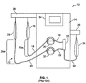
- Fig. 1 there is seen a schematic representation of a typical apheresis system 10 comprising a single-use fluid processing kit 12 and a durable hardware component 14.
- the system 10 is particularly well suited to processing whole blood and/or other suspensions of biological fluids.
- the systems and methods described herein are particularly suited for a the processing of mononuclear cells (MNC), during which the MNCs separated from the fluid in which they are suspended for further processing before administering to a patient.
- MNC mononuclear cells
- the fluid processing kit 12 includes a source container 16 connected by tubing 18 to define a flow path to the inlet of a separation device 20.
- the separation device is preferably a membrane separator, and, more preferably a spinning membrane separator.
- the separation device may comprise a chamber that is part of a centrifugal separator.
- a detailed description of a spinning membrane separator may be found in U.S. Patent No. 5,194,145 to Schoendorfer .
- This patent describes a membrane-covered spinner having an interior collection system disposed within a stationary shell.
- the membrane separator includes two outlets. One outlet is connected by tubing 22 to define a flow path to a container 24 for receiving the filtrate, which is typically considered waste.
- the second outlet is connected by tubing 26 to define a flow path to a container 28 for receiving the precipitate, which is typically the desired cellular component and the final product of the apheresis procedure.
- the durable hardware component 14 preferably includes one or more flow controlling devices, such as, for example, pumps, such as peristaltic or diaphragm pumps, generally indicated at 30 and 32, that are preferably respectively associated with the tubings 18 and 26 for controlling fluid flow of the fluid suspension from the source container 16 to the membrane separator 20 and the flow of the precipitate from the membrane separator to the final product container 28.
- flow controlling devices such as, for example, pumps, such as peristaltic or diaphragm pumps, generally indicated at 30 and 32, that are preferably respectively associated with the tubings 18 and 26 for controlling fluid flow of the fluid suspension from the source container 16 to the membrane separator 20 and the flow of the precipitate from the membrane separator to the final product container 28.
- Other types of flow controlling devices may also be used as controllers, including but not limited to gravity-controlled flow controllers.
- the durable hardware component 14 also typically includes a programmable controller 34 employing a programmable microprocessor, a drive system (not shown) for the membrane separator 20 (if the separator 20 is a spinning membrane separator), and hangers 36, typically including weight scales, from which the various containers 16, 24 and 28 are suspended, with their respective tubings 18, 22 and 26 being routed vertically downwards.
- a programmable controller 34 employing a programmable microprocessor, a drive system (not shown) for the membrane separator 20 (if the separator 20 is a spinning membrane separator), and hangers 36, typically including weight scales, from which the various containers 16, 24 and 28 are suspended, with their respective tubings 18, 22 and 26 being routed vertically downwards.
- MNCs As noted above, the processing of MNCs, as well as other biological fluids, is often a discontinuous process, with the source and product containers being left un-agitated for a period of time. During this time, the MNCs will tend to settle out of suspension and out of the containers 18 and 26 into the vertical portions 18a and 26a of the tubings 18 and 26.
- the MNC's in the product container 28 that settle into the vertical portion 26a of the tubing 26 cannot be recovered and must be treated as waste, as they cannot be pumped back into the product container due to tightly-controlled processing protocols.
- the fluid processing kit is provided with a configuration that minimizes the amount of cellular components that may settle out of the container containing the suspension. More particularly, the flow path from either or both the source container and product container is provided with a segment in close proximity to the container that has a configuration including a positive slope, i.e., point in an upward direction, so that cellular components moving through the segment are subjected to a gravitational force tending to impede movement through the flow path segment, thus limiting the amount of cellular material settling in the flow path.
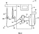
- the flow paths defined by the tubings 18 and 26 are provided with segments adjacent their associated containers that include an upward or positive slope.
- the positive-sloping segment of tubing 18 may be provided with an S-shaped configuration 18b.
- the positive-sloping segment of tubing may have a looped or circular configuration, in which the tubing segment 26 has a circular configuation 26b.
- the tubing segments 18b and 26b are better seen in Figs. 3 an 4, respectively, where the positive-slope for the segments is indicated by the diagonally-oriented lines 38, and the settled cellular material is represented by the shading 40.
- the positively-sloped segment of the tubing may be maintained by, e.g. an adhesive that secures the overlapping portions the looped tubing configuration ( Fig. 4 ) to each other.
- a clamp or clip may be employed, as described in greater detail below in connection with Figs. 5 and 6 .
- the tubing segment may be thermoformed to maintain its desired configuration.
- the containers 16 and 28 are typically flexible plastic pouches or bags formed of opposed sheets sealed together at their peripheral edges with a port or tube positioned between the sheets to provide access to the interior, with the tubing, such as tubing 18 and 26, being secured to the port.
- a looped tubing segment 42 is seen connected to and extending from an access port 44 that is associated with a peripheral edge of a pouch (not seen).
- a clip 46 maintains the looped or circular configuration of the tubing segment 42 by engaging the overlapping portions of the tubing.
- the clip 46 is located on the tubing segment 42 in close proximity to the access port 44 in order to minimize the amount of tubing into which cellular components may settle.
- FIG. 6 discloses a flexible container 48 having a looped tubing segment 42 and port 44 arrangement similar to Fig. 5 , with the clip 46 for maintaining the configuration in abutment with the access port.
- the container 48 also includes auxiliary ports 50, 52 having tubing segments 54 and 56 associated therewith to provide access to the interior of the container to, e.g., draw samples, infuse a treatment solution, etc.
- a single-use fluid circuit for processing a fluid including a suspension of biological cellular components comprises a container for the fluid; a separation device for retaining selected biological cellular components and allowing other biological cellular components of said fluid to pass therethrough; a flow path connecting the container to the separation device and defined by a tubing that is routed vertically downwards from the container and then directed generally laterally toward the separation device, with the container being configured, when in use, to be positioned so that gravity tends to flow fluid through the flow path.
- the flow path includes a segment in close proximity to the container having a configuration including a positive slope, so that biological cellular components moving through the segment are subjected to a gravitational force tending to impede movement through the flow path segment.
- a procedure for processing a fluid including a suspension of biological cellular components utilizes a single use fluid circuit comprising a container for the fluid connected by a flow path to a separation device, the flow path being configured to be selectively draw fluid through the tubing, a method for reducing the accumulation of cellular material in the tubing during time periods when the procedure is interrupted.
- the method comprises providing a segment of the flow path in close proximity to the container with a positive slope, so that cellular components moving through the segment are subjected to a gravitational force tending to impede movement through the tubing segment toward the separator.
- a system for processing biological fluids including cellular components comprises a single-use kit having a container for the biological fluid, a separation device, and a flow path providing fluid communication between the collection container and the membrane separator, and defined by a tubing that is routed vertically downwards from the container and then directed generally laterally toward the separation device.
- the system further includes a reusable hardware component for selectively flowing the biological fluid between the container and the separator, and the flow path further comprises a segment in close proximity to the container having a configuration including a positive slope, so that biological cellular components moving through the segment are subjected to a gravitational force tending to impede movement through the flow path segment.
- the flow path segment may have a generally circular configuration or, alternatively, a generally S-shaped configuration; the configuration of the flow path segment may be maintained by an adhesive or, alternatively, the configuration of the flow path segment may be maintained by a clamp; and/or the fluid circuit may further comprising an access port for connecting the flow path to the collection container, with the flow path segment being connected adjacent to the access port.
- the separation device may be a membrane separator, such as a spinning membrane separator, or may be a centrifugal separation device.
Landscapes
- Health & Medical Sciences (AREA)
- Heart & Thoracic Surgery (AREA)
- Vascular Medicine (AREA)
- Engineering & Computer Science (AREA)
- Life Sciences & Earth Sciences (AREA)
- Veterinary Medicine (AREA)
- Biomedical Technology (AREA)
- Hematology (AREA)
- Anesthesiology (AREA)
- Animal Behavior & Ethology (AREA)
- General Health & Medical Sciences (AREA)
- Public Health (AREA)
- Cardiology (AREA)
- External Artificial Organs (AREA)
- Urology & Nephrology (AREA)
- Water Supply & Treatment (AREA)
- Chemical & Material Sciences (AREA)
- Chemical Kinetics & Catalysis (AREA)
- Separation Using Semi-Permeable Membranes (AREA)
Description
- The present application is related to systems and methods for performing apheresis procedures, and, more particularly to systems and methods for minimizing the loss of desired cellular material and the potential for clogging or fouling in the case of membrane separation.
- Apheresis is a medical procedure in which the blood of a donor or patient is passed through an apparatus that separates out one or more of the cellular components (such as plasma, red blood cells, leukocytes and platelets). Separation of the cellular components is commonly accomplished by centrifugation, based on the difference in density of the cellular components, or by membrane separation, based on the particle size. In either instance, a single use fluid circuit or kit is used in conjunction with a hardware component, with the kit typically including a source container, containing the whole blood or other biological fluid to be processed, connected (or connectable) to a fluid flow path, typically defined by a tubing, to the separator device, which, in turn, is connected to a flow path to a product container for receiving the desired cellular component. The hardware component typically comprises a plurality of pumps, valves and/or clamps for controlling flow through the kit, and a controller for operating the same.
- When the kit is mounted to the hardware component, source and product containers are typically suspended from weight scales, with the tubings connected to the source and product containers routed vertically downwards and then directed generally laterally toward the separator device, which is mounted to the face of the hardware component. Alternatively, such as disclosed in
WO2013/043433 , the tubings connected to the source and product containers may be routed vertically upwards and then directed generally laterally toward the separator device. If during an apheresis procedure, the procedure requires intermittent flow (e.g., to test samples for cell count viability, etc.) or is otherwise interrupted, and the source and/or product containers are left un-agitated for a period of time, heavier cellular material will separate out and settle in the vertical portions of the tubing connected to the containers, particularly below the container. The settled cellular material in the tubings cannot be recovered back into the containers, and may thus be permanently lost (if settled from the tubing connected to the product container) or cause a high concentration of cellular material to reach the separator device upon resumption of the procedure that could create unexpected pressure changes in the system and clogging of the separator. - By way of the systems and methods disclosed herein, a solution to the foregoing problems is provided.
- The invention is defined in the appended claims.
- In a first aspect of the present disclosure, a single-use fluid circuit for processing a fluid including a suspension of biological cellular components is provided comprising a container for the fluid; a separation device for retaining selected cellular components and allowing other cellular components of said fluid to pass therethrough; and a flow path connecting the container to the separation device defined by a tubing that is routed vertically downwards from the container and then directed generally laterally toward the separation device. The container is configured, when in use, to be positioned so that gravity tends to cause cellular that settles out of suspension to flow into the flow path. The flow path comprises a segment in close proximity to the container with a configuration including an upward or positive slope, so that cellular components moving through the segment are subjected to a gravitational force tending to impede movement through the flow path segment.
- In another aspect, the flow path segment of the fluid circuit has a generally circular configuration, and preferably has a diameter of approximately 1.5 inches. As an alternative, the flow path segment may have a generally S-shaped configuration.
- In a further aspect, configuration of the flow path segment may be maintained by an adhesive. As an alternative, the configuration of the flow path segment may be maintained by a clamp.
- In another aspect, the single-use fluid circuit may comprise an access site for connecting the flow path to the collection container, with the flow path segment being connected directly, or otherwise as close as possible, to the access site.
- In a second aspect of the disclosure, a method is provided for reducing the accumulation of cellular material in the tubing during time periods when a procedure for processing a fluid including a suspension of biological cellular components utilizing a single use fluid circuit comprising a container for the fluid connected by a flow path to a separation device is interrupted. The flow path is defined by a tubing that is routed vertically downwards from the container and then directed generally laterally toward the separation device The method comprises providing a segment of the flow path in close proximity to the container with a positive slope, so that cellular components moving through the segment are subjected to a gravitational force tending to impede movement through the tubing segment toward the separation device. In related aspects, the flow path segment is provided with the configurations as set forth above.
- In a third aspect, the present disclosure provides a system for processing biological fluids including cellular components comprising a single-use kit comprising a container for the biological fluid, a separation device, and a flow path providing fluid communication between the container and the separation device, as defined by a tubing that is routed vertically downwards from the container and then directed generally laterally toward the separation device; a reusable hardware component for selectively flowing the biological fluid between the container and the separator; with the flow path further comprising having a segment in close proximity to the container with a configuration including a positive slope, so that biological cellular components moving through the segment are subjected to a gravitational force tending to impede movement through the flow path segment.
- In any of its aspects, the separator may comprise a membrane separator, and, more specifically, a spinning membrane separator.
-
-
Fig. 1 is a schematic representation of a prior art apheresis system including a single-use fluid processing kit and a durable hardware component. -
Fig. 2 is a schematic representation of an apheresis system including a single-use fluid processing kit and a durable hardware component in accordance with the present disclosure. -
Figs. 3 and 4 are enlarged fragmentary views of a portion of the tubing comprising the single-use fluid processing kit shown inFig.2 . -
Figs 5 and 6 are alternate embodiments of the tubing configuration shown inFig. 3 . - A more detailed description of the systems and methods in accordance with the present disclosure is set forth below. It should be understood that the description below of specific devices and methods is intended to be exemplary, and not exhaustive of all possible variations or applications. Thus, the scope of the disclosure is not intended to be limiting, and should be understood to encompass variations or embodiments that would occur to persons of ordinary skill.
- Turning to
Fig. 1 , there is seen a schematic representation of atypical apheresis system 10 comprising a single-usefluid processing kit 12 and adurable hardware component 14. Thesystem 10 is particularly well suited to processing whole blood and/or other suspensions of biological fluids. By way of example and not limitation, the systems and methods described herein are particularly suited for a the processing of mononuclear cells (MNC), during which the MNCs separated from the fluid in which they are suspended for further processing before administering to a patient. - As illustrated, the
fluid processing kit 12 includes asource container 16 connected bytubing 18 to define a flow path to the inlet of aseparation device 20. The separation device is preferably a membrane separator, and, more preferably a spinning membrane separator. Alternatively, the separation device may comprise a chamber that is part of a centrifugal separator. - A detailed description of a spinning membrane separator may be found in
U.S. Patent No. 5,194,145 to Schoendorfer . This patent describes a membrane-covered spinner having an interior collection system disposed within a stationary shell. The membrane separator includes two outlets. One outlet is connected bytubing 22 to define a flow path to acontainer 24 for receiving the filtrate, which is typically considered waste. The second outlet is connected bytubing 26 to define a flow path to acontainer 28 for receiving the precipitate, which is typically the desired cellular component and the final product of the apheresis procedure. - The
durable hardware component 14 preferably includes one or more flow controlling devices, such as, for example, pumps, such as peristaltic or diaphragm pumps, generally indicated at 30 and 32, that are preferably respectively associated with thetubings source container 16 to themembrane separator 20 and the flow of the precipitate from the membrane separator to thefinal product container 28. Other types of flow controlling devices may also be used as controllers, including but not limited to gravity-controlled flow controllers. Thedurable hardware component 14 also typically includes aprogrammable controller 34 employing a programmable microprocessor, a drive system (not shown) for the membrane separator 20 (if theseparator 20 is a spinning membrane separator), andhangers 36, typically including weight scales, from which thevarious containers respective tubings - As noted above, the processing of MNCs, as well as other biological fluids, is often a discontinuous process, with the source and product containers being left un-agitated for a period of time. During this time, the MNCs will tend to settle out of suspension and out of the
containers vertical portions tubings - If the MNCs settle into the
vertical portion 18a of thetubing 18 from thesource container 16, upon resumption of the membrane separation, a high concentration of MNCs will initially reach the membrane separator, potentially exceeding its filtration capacity and resulting in clogging or fouling of the membrane. - If, during a pause in the processing to permit, e.g., samples of the separated MNCs to be taken from the
product container 28 and analyzed for cell counts, viability, etc., the MNC's in theproduct container 28 that settle into thevertical portion 26a of thetubing 26 cannot be recovered and must be treated as waste, as they cannot be pumped back into the product container due to tightly-controlled processing protocols. - By way of the present disclosure, the fluid processing kit is provided with a configuration that minimizes the amount of cellular components that may settle out of the container containing the suspension. More particularly, the flow path from either or both the source container and product container is provided with a segment in close proximity to the container that has a configuration including a positive slope, i.e., point in an upward direction, so that cellular components moving through the segment are subjected to a gravitational force tending to impede movement through the flow path segment, thus limiting the amount of cellular material settling in the flow path.
- With reference to
Fig. 2 , in which elements common toFig. 1 are, provided with like reference numerals, the flow paths defined by thetubings tubing 18 may be provided with an S-shaped configuration 18b. Alternatively, the positive-sloping segment of tubing may have a looped or circular configuration, in which thetubing segment 26 has acircular configuation 26b. Thetubing segments Figs. 3 an 4, respectively, where the positive-slope for the segments is indicated by the diagonally-orientedlines 38, and the settled cellular material is represented by theshading 40. - The positively-sloped segment of the tubing may be maintained by, e.g. an adhesive that secures the overlapping portions the looped tubing configuration (
Fig. 4 ) to each other. Alternatively, a clamp or clip may be employed, as described in greater detail below in connection withFigs. 5 and 6 . As a further alternative, the tubing segment may be thermoformed to maintain its desired configuration. - The
containers tubing Fig. 5 , a loopedtubing segment 42 is seen connected to and extending from anaccess port 44 that is associated with a peripheral edge of a pouch (not seen). Aclip 46 maintains the looped or circular configuration of thetubing segment 42 by engaging the overlapping portions of the tubing. Theclip 46 is located on thetubing segment 42 in close proximity to theaccess port 44 in order to minimize the amount of tubing into which cellular components may settle.Fig. 6 discloses aflexible container 48 having a loopedtubing segment 42 andport 44 arrangement similar toFig. 5 , with theclip 46 for maintaining the configuration in abutment with the access port. Thecontainer 48 also includesauxiliary ports tubing segments - Thus, systems and methods for minimizing loss of cellular components during apheresis have been disclosed having several aspects.
- In a first aspect of the disclosure, a single-use fluid circuit for processing a fluid including a suspension of biological cellular components is provided that comprises a container for the fluid; a separation device for retaining selected biological cellular components and allowing other biological cellular components of said fluid to pass therethrough; a flow path connecting the container to the separation device and defined by a tubing that is routed vertically downwards from the container and then directed generally laterally toward the separation device, with the container being configured, when in use, to be positioned so that gravity tends to flow fluid through the flow path. The flow path includes a segment in close proximity to the container having a configuration including a positive slope, so that biological cellular components moving through the segment are subjected to a gravitational force tending to impede movement through the flow path segment.
- In a second aspect of the disclosure, a procedure for processing a fluid including a suspension of biological cellular components is disclosed that utilizes a single use fluid circuit comprising a container for the fluid connected by a flow path to a separation device, the flow path being configured to be selectively draw fluid through the tubing, a method for reducing the accumulation of cellular material in the tubing during time periods when the procedure is interrupted. The method comprises providing a segment of the flow path in close proximity to the container with a positive slope, so that cellular components moving through the segment are subjected to a gravitational force tending to impede movement through the tubing segment toward the separator.
- In a third aspect, a system for processing biological fluids including cellular components is provided that comprises a single-use kit having a container for the biological fluid, a separation device, and a flow path providing fluid communication between the collection container and the membrane separator, and defined by a tubing that is routed vertically downwards from the container and then directed generally laterally toward the separation device. The system further includes a reusable hardware component for selectively flowing the biological fluid between the container and the separator, and the flow path further comprises a segment in close proximity to the container having a configuration including a positive slope, so that biological cellular components moving through the segment are subjected to a gravitational force tending to impede movement through the flow path segment.
- In any of its aspects, the flow path segment may have a generally circular configuration or, alternatively, a generally S-shaped configuration; the configuration of the flow path segment may be maintained by an adhesive or, alternatively, the configuration of the flow path segment may be maintained by a clamp; and/or the fluid circuit may further comprising an access port for connecting the flow path to the collection container, with the flow path segment being connected adjacent to the access port. Further, the separation device may be a membrane separator, such as a spinning membrane separator, or may be a centrifugal separation device.
Claims (15)
- A single-use fluid circuit (12) for processing a fluid including a suspension of biological cellular components configured for use in combination with a hardware component (14) of an apheresis system (10) comprising one or more flow controlling devices (30, 32) and hangers (36), comprising:a) a container (16, 24, 28) for the fluid, which is configured, when in use, to suspend from a hanger (36) from the hardware component (14);b) a separation device (20) for retaining selected biological cellular components and allowing other biological cellular components of said fluid to pass therethrough;c) a tubing (18, 22, 26) connecting the container (16, 24, 28) to the separation device (20), wherein in use the tubing (18, 22, 26) defines a flow path that is routed vertically downwards from the container (16, 24, 28) and then directed generally laterally toward the separation device (20) and wherein in use a flow controlling device (30, 32) is associated with the tubing (18, 26) for controlling fluid flow therein,wherein the tubing (18, 26) has a segment (18b, 26b, 42) in close proximity to the container (16, 28) with a configuration including a positive slope, said configuration being provided and maintained in the single-use fluid circuit (12), so that when in use during an interruption in an apheresis procedure the container (16, 28) is left unagitated for a period of time, biological cellular components moving through the tubing segment (18b, 26b, 42) are subjected to a gravitational force tending to impede movement through the flow path segment (18b, 26b, 42).
- The single-use fluid circuit (12) of Claim 1 in which the tubing segment (26b, 42) has a generally circular configuration.
- The single-use fluid circuit (12) of Claim 1 or 2 in which the tubing segment (18b) has a generally S-shaped configuration.
- The single-use fluid circuit (12) of any of the Claims 1-3, in which the configuration of the tubing segment (18b, 26b, 42) is maintained by an adhesive.
- The single-use fluid circuit (12) of any of the Claims 1-3 in which the configuration of the tubing segment (18b, 26b, 42) is maintained by a clamp (44).
- The single use fluid circuit (12) of any of the claims 1-3, wherein the tubing segment (18b, 26b, 44) is thermoformed to maintain the configuration including the positive slope.
- The single-use fluid circuit (12) of any one of Claims 1-6 further comprising an access port (44) for connecting the tubing (26) to the product container (28), the tubing segment (26b, 42) being connected adjacent to the access port (44).
- The single-use fluid circuit (12) according to any of the preceding claims, in which the separation device (20) is a membrane separator, preferably the separator has a spinning membrane.
- An apheresis system (10) comprising a hardware component (14) and a single-use fluid circuit (12), wherein the hardware component (14) comprises one or more flow controlling devices (30, 32) and hangers (36), and wherein the single-use fluid circuit (12) as claimed in any of the preceding claims 1-8 is present.
- A method for processing a fluid including a suspension of biological cellular components, comprising the steps of:utilizing a single-use fluid circuit (12) comprising a source container (16) and a product container (28) for the fluid, each of which containers (16, 24) is connected by tubing (18, 26) to a separation device (20) of the fluid circuit (12), wherein the tubing (18, 26) from either or both the source container (16) and the product container (28) comprises a tubing segment (18b, 26b, 42) in close proximity to the container (16, 28) with a configuration including a positive slope,mounting the single-use fluid circuit (12) to a hardware component (14) to form an apheresis system (10), the hardware component (14) comprising hangers (36) for suspending the source container (16) and the product container (28) and flow controlling devices (30, 32) associated with the tubings (18, 26), wherein the tubing (18, 26) defines a flow path that is routed vertically downwards from the source container (16) and the product container (28), and then directed generally laterally toward the separation device (20);controlling fluid flow of the fluid suspension from the source container (16) to the separation device (20) and from the separation device (20) to the product container (28) by means of the flow controlling devices (30, 32) in a discontinuous manner, with the source and product containers (16, 28) being left unagitated for a period of time, wherein cellular components moving through the said tubing segment (18b, 26b) with a positive slope are subjected to a gravitational force tending to impede movement through the tubing segment (18b, 26b) toward the separation device (20).
- The method of claim 10, wherein the said tubing segment (26b) of the single-use fluid circuit (12) is provided with a generally circular configuration.
- The method of claim 10 or 11, wherein the said tubing segment (18b) of the single-use fluid circuit (12) is provided with a generally S-shaped configuration.
- The method of any of the claims 10-12, wherein the single-use fluid circuit (12) further comprises an adhesive or a clamp (46) for maintaining the configuration of the said tubing segment (18b, 26b, 42).
- The method according to any of the claims 10-14 in which the separation device (20) is a membrane separator, which membrane separator preferably has a spinning membrane.
- The method according to any of the claims 10-14, wherein the fluid including a suspension of biological cellular components is a suspension of mononuclear cells.
Applications Claiming Priority (1)
| Application Number | Priority Date | Filing Date | Title |
|---|---|---|---|
| US14/050,948 US9821110B2 (en) | 2013-10-10 | 2013-10-10 | Systems and methods for minimizing loss of cellular components during apheresis |
Publications (2)
| Publication Number | Publication Date |
|---|---|
| EP2859905A1 EP2859905A1 (en) | 2015-04-15 |
| EP2859905B1 true EP2859905B1 (en) | 2018-08-15 |
Family
ID=49517262
Family Applications (1)
| Application Number | Title | Priority Date | Filing Date |
|---|---|---|---|
| EP13189811.6A Active EP2859905B1 (en) | 2013-10-10 | 2013-10-23 | Systems and methods for minimizing loss of cellular components during apheresis |
Country Status (2)
| Country | Link |
|---|---|
| US (1) | US9821110B2 (en) |
| EP (1) | EP2859905B1 (en) |
Families Citing this family (1)
| Publication number | Priority date | Publication date | Assignee | Title |
|---|---|---|---|---|
| SG10202003075UA (en) | 2015-06-05 | 2020-05-28 | Novartis Ag | Flow-through paramagnetic particle-based cell separation and paramagnetic particle removal |
Family Cites Families (5)
| Publication number | Priority date | Publication date | Assignee | Title |
|---|---|---|---|---|
| JPS61501494A (en) * | 1984-03-21 | 1986-07-24 | マクロ−リン、ウイリアム フランシス | Equipment for separating substances from suspensions |
| US5126054A (en) | 1990-05-24 | 1992-06-30 | Pall Corporation | Venting means |
| US7854845B2 (en) | 2003-09-05 | 2010-12-21 | Hemerus Medical Llc | Biological fluid filtration apparatus |
| US7708710B2 (en) | 2003-12-23 | 2010-05-04 | Fenwal, Inc. | Method and apparatus for collecting and processing blood |
| WO2013043433A2 (en) | 2011-09-22 | 2013-03-28 | Fenwal, Inc. | Disposable fluid circuits and methods for cell washing |
-
2013
- 2013-10-10 US US14/050,948 patent/US9821110B2/en active Active
- 2013-10-23 EP EP13189811.6A patent/EP2859905B1/en active Active
Non-Patent Citations (1)
| Title |
|---|
| None * |
Also Published As
| Publication number | Publication date |
|---|---|
| US20150101994A1 (en) | 2015-04-16 |
| EP2859905A1 (en) | 2015-04-15 |
| US9821110B2 (en) | 2017-11-21 |
Similar Documents
| Publication | Publication Date | Title |
|---|---|---|
| CN109069714B (en) | Multiple blood bag system | |
| AU667282B2 (en) | System and method for processing biological fluid | |
| US8469202B2 (en) | Processing bag for component separator system and method of removing separated components | |
| EP2720730B1 (en) | Disposable fluid circuits and methods for cell washing | |
| EP3331586B1 (en) | Tangential flow filter system for the filtration of materials from biologic fluids | |
| US20250136930A1 (en) | Systems and methods for the separation of cells from microcarriers using a spinning membrane | |
| WO2012064754A2 (en) | Component preparation system | |
| US20210106747A1 (en) | Systems and methods for automated recovery of white blood cells after producing a leuko-reduced blood product | |
| US10857269B2 (en) | Cassette having an integrated filter and bypass | |
| US9821110B2 (en) | Systems and methods for minimizing loss of cellular components during apheresis | |
| EP4183432A1 (en) | Fluid treatment method and fluid treatment device | |
| EP3000495B1 (en) | Systems for controlling the return phase of a blood separation procedure | |
| US11291953B2 (en) | System and method for controlling outlet flow of a device for separating cellular suspensions | |
| EP3277335B1 (en) | Systems and methods for leukoreducing a red blood cell-containing fluid and concentrated red blood cells | |
| JP2022115928A (en) | Systems and methods for platelet filtration using additives | |
| EP4008374B1 (en) | Priming of spinning membrane separators | |
| EP3335743A2 (en) | Systems and methods for recovering white blood cells from a leukoreduction filter | |
| EP3362115B1 (en) | Fluid processing and circuit array, system and apparatus |
Legal Events
| Date | Code | Title | Description |
|---|---|---|---|
| PUAI | Public reference made under article 153(3) epc to a published international application that has entered the european phase |
Free format text: ORIGINAL CODE: 0009012 |
|
| 17P | Request for examination filed |
Effective date: 20131125 |
|
| AK | Designated contracting states |
Kind code of ref document: A1 Designated state(s): AL AT BE BG CH CY CZ DE DK EE ES FI FR GB GR HR HU IE IS IT LI LT LU LV MC MK MT NL NO PL PT RO RS SE SI SK SM TR |
|
| AX | Request for extension of the european patent |
Extension state: BA ME |
|
| 17Q | First examination report despatched |
Effective date: 20170127 |
|
| REG | Reference to a national code |
Ref country code: DE Ref legal event code: R079 Ref document number: 602013041947 Country of ref document: DE Free format text: PREVIOUS MAIN CLASS: A61M0001340000 Ipc: A61M0001360000 |
|
| RIC1 | Information provided on ipc code assigned before grant |
Ipc: A61M 1/36 20060101AFI20180228BHEP Ipc: A61M 1/34 20060101ALI20180228BHEP Ipc: B01D 61/24 20060101ALI20180228BHEP |
|
| GRAP | Despatch of communication of intention to grant a patent |
Free format text: ORIGINAL CODE: EPIDOSNIGR1 |
|
| INTG | Intention to grant announced |
Effective date: 20180410 |
|
| GRAS | Grant fee paid |
Free format text: ORIGINAL CODE: EPIDOSNIGR3 |
|
| GRAA | (expected) grant |
Free format text: ORIGINAL CODE: 0009210 |
|
| AK | Designated contracting states |
Kind code of ref document: B1 Designated state(s): AL AT BE BG CH CY CZ DE DK EE ES FI FR GB GR HR HU IE IS IT LI LT LU LV MC MK MT NL NO PL PT RO RS SE SI SK SM TR |
|
| REG | Reference to a national code |
Ref country code: CH Ref legal event code: EP Ref country code: GB Ref legal event code: FG4D Ref country code: AT Ref legal event code: REF Ref document number: 1029018 Country of ref document: AT Kind code of ref document: T Effective date: 20180815 |
|
| REG | Reference to a national code |
Ref country code: IE Ref legal event code: FG4D |
|
| REG | Reference to a national code |
Ref country code: DE Ref legal event code: R096 Ref document number: 602013041947 Country of ref document: DE |
|
| REG | Reference to a national code |
Ref country code: FR Ref legal event code: PLFP Year of fee payment: 6 |
|
| REG | Reference to a national code |
Ref country code: NL Ref legal event code: MP Effective date: 20180815 |
|
| REG | Reference to a national code |
Ref country code: LT Ref legal event code: MG4D |
|
| REG | Reference to a national code |
Ref country code: AT Ref legal event code: MK05 Ref document number: 1029018 Country of ref document: AT Kind code of ref document: T Effective date: 20180815 |
|
| PG25 | Lapsed in a contracting state [announced via postgrant information from national office to epo] |
Ref country code: RS Free format text: LAPSE BECAUSE OF FAILURE TO SUBMIT A TRANSLATION OF THE DESCRIPTION OR TO PAY THE FEE WITHIN THE PRESCRIBED TIME-LIMIT Effective date: 20180815 Ref country code: IS Free format text: LAPSE BECAUSE OF FAILURE TO SUBMIT A TRANSLATION OF THE DESCRIPTION OR TO PAY THE FEE WITHIN THE PRESCRIBED TIME-LIMIT Effective date: 20181215 Ref country code: SE Free format text: LAPSE BECAUSE OF FAILURE TO SUBMIT A TRANSLATION OF THE DESCRIPTION OR TO PAY THE FEE WITHIN THE PRESCRIBED TIME-LIMIT Effective date: 20180815 Ref country code: BG Free format text: LAPSE BECAUSE OF FAILURE TO SUBMIT A TRANSLATION OF THE DESCRIPTION OR TO PAY THE FEE WITHIN THE PRESCRIBED TIME-LIMIT Effective date: 20181115 Ref country code: LT Free format text: LAPSE BECAUSE OF FAILURE TO SUBMIT A TRANSLATION OF THE DESCRIPTION OR TO PAY THE FEE WITHIN THE PRESCRIBED TIME-LIMIT Effective date: 20180815 Ref country code: NL Free format text: LAPSE BECAUSE OF FAILURE TO SUBMIT A TRANSLATION OF THE DESCRIPTION OR TO PAY THE FEE WITHIN THE PRESCRIBED TIME-LIMIT Effective date: 20180815 Ref country code: FI Free format text: LAPSE BECAUSE OF FAILURE TO SUBMIT A TRANSLATION OF THE DESCRIPTION OR TO PAY THE FEE WITHIN THE PRESCRIBED TIME-LIMIT Effective date: 20180815 Ref country code: NO Free format text: LAPSE BECAUSE OF FAILURE TO SUBMIT A TRANSLATION OF THE DESCRIPTION OR TO PAY THE FEE WITHIN THE PRESCRIBED TIME-LIMIT Effective date: 20181115 Ref country code: GR Free format text: LAPSE BECAUSE OF FAILURE TO SUBMIT A TRANSLATION OF THE DESCRIPTION OR TO PAY THE FEE WITHIN THE PRESCRIBED TIME-LIMIT Effective date: 20181116 Ref country code: AT Free format text: LAPSE BECAUSE OF FAILURE TO SUBMIT A TRANSLATION OF THE DESCRIPTION OR TO PAY THE FEE WITHIN THE PRESCRIBED TIME-LIMIT Effective date: 20180815 |
|
| PG25 | Lapsed in a contracting state [announced via postgrant information from national office to epo] |
Ref country code: HR Free format text: LAPSE BECAUSE OF FAILURE TO SUBMIT A TRANSLATION OF THE DESCRIPTION OR TO PAY THE FEE WITHIN THE PRESCRIBED TIME-LIMIT Effective date: 20180815 Ref country code: LV Free format text: LAPSE BECAUSE OF FAILURE TO SUBMIT A TRANSLATION OF THE DESCRIPTION OR TO PAY THE FEE WITHIN THE PRESCRIBED TIME-LIMIT Effective date: 20180815 Ref country code: AL Free format text: LAPSE BECAUSE OF FAILURE TO SUBMIT A TRANSLATION OF THE DESCRIPTION OR TO PAY THE FEE WITHIN THE PRESCRIBED TIME-LIMIT Effective date: 20180815 |
|
| PG25 | Lapsed in a contracting state [announced via postgrant information from national office to epo] |
Ref country code: RO Free format text: LAPSE BECAUSE OF FAILURE TO SUBMIT A TRANSLATION OF THE DESCRIPTION OR TO PAY THE FEE WITHIN THE PRESCRIBED TIME-LIMIT Effective date: 20180815 Ref country code: CZ Free format text: LAPSE BECAUSE OF FAILURE TO SUBMIT A TRANSLATION OF THE DESCRIPTION OR TO PAY THE FEE WITHIN THE PRESCRIBED TIME-LIMIT Effective date: 20180815 Ref country code: IT Free format text: LAPSE BECAUSE OF FAILURE TO SUBMIT A TRANSLATION OF THE DESCRIPTION OR TO PAY THE FEE WITHIN THE PRESCRIBED TIME-LIMIT Effective date: 20180815 Ref country code: EE Free format text: LAPSE BECAUSE OF FAILURE TO SUBMIT A TRANSLATION OF THE DESCRIPTION OR TO PAY THE FEE WITHIN THE PRESCRIBED TIME-LIMIT Effective date: 20180815 Ref country code: ES Free format text: LAPSE BECAUSE OF FAILURE TO SUBMIT A TRANSLATION OF THE DESCRIPTION OR TO PAY THE FEE WITHIN THE PRESCRIBED TIME-LIMIT Effective date: 20180815 Ref country code: PL Free format text: LAPSE BECAUSE OF FAILURE TO SUBMIT A TRANSLATION OF THE DESCRIPTION OR TO PAY THE FEE WITHIN THE PRESCRIBED TIME-LIMIT Effective date: 20180815 |
|
| REG | Reference to a national code |
Ref country code: DE Ref legal event code: R097 Ref document number: 602013041947 Country of ref document: DE |
|
| PG25 | Lapsed in a contracting state [announced via postgrant information from national office to epo] |
Ref country code: SK Free format text: LAPSE BECAUSE OF FAILURE TO SUBMIT A TRANSLATION OF THE DESCRIPTION OR TO PAY THE FEE WITHIN THE PRESCRIBED TIME-LIMIT Effective date: 20180815 Ref country code: SM Free format text: LAPSE BECAUSE OF FAILURE TO SUBMIT A TRANSLATION OF THE DESCRIPTION OR TO PAY THE FEE WITHIN THE PRESCRIBED TIME-LIMIT Effective date: 20180815 Ref country code: DK Free format text: LAPSE BECAUSE OF FAILURE TO SUBMIT A TRANSLATION OF THE DESCRIPTION OR TO PAY THE FEE WITHIN THE PRESCRIBED TIME-LIMIT Effective date: 20180815 |
|
| REG | Reference to a national code |
Ref country code: CH Ref legal event code: PL |
|
| PLBE | No opposition filed within time limit |
Free format text: ORIGINAL CODE: 0009261 |
|
| STAA | Information on the status of an ep patent application or granted ep patent |
Free format text: STATUS: NO OPPOSITION FILED WITHIN TIME LIMIT |
|
| REG | Reference to a national code |
Ref country code: BE Ref legal event code: MM Effective date: 20181031 |
|
| PG25 | Lapsed in a contracting state [announced via postgrant information from national office to epo] |
Ref country code: MC Free format text: LAPSE BECAUSE OF FAILURE TO SUBMIT A TRANSLATION OF THE DESCRIPTION OR TO PAY THE FEE WITHIN THE PRESCRIBED TIME-LIMIT Effective date: 20180815 Ref country code: LU Free format text: LAPSE BECAUSE OF NON-PAYMENT OF DUE FEES Effective date: 20181023 |
|
| 26N | No opposition filed |
Effective date: 20190516 |
|
| REG | Reference to a national code |
Ref country code: IE Ref legal event code: MM4A |
|
| PG25 | Lapsed in a contracting state [announced via postgrant information from national office to epo] |
Ref country code: LI Free format text: LAPSE BECAUSE OF NON-PAYMENT OF DUE FEES Effective date: 20181031 Ref country code: CH Free format text: LAPSE BECAUSE OF NON-PAYMENT OF DUE FEES Effective date: 20181031 Ref country code: SI Free format text: LAPSE BECAUSE OF FAILURE TO SUBMIT A TRANSLATION OF THE DESCRIPTION OR TO PAY THE FEE WITHIN THE PRESCRIBED TIME-LIMIT Effective date: 20180815 Ref country code: BE Free format text: LAPSE BECAUSE OF NON-PAYMENT OF DUE FEES Effective date: 20181031 |
|
| PG25 | Lapsed in a contracting state [announced via postgrant information from national office to epo] |
Ref country code: IE Free format text: LAPSE BECAUSE OF NON-PAYMENT OF DUE FEES Effective date: 20181023 |
|
| PG25 | Lapsed in a contracting state [announced via postgrant information from national office to epo] |
Ref country code: MT Free format text: LAPSE BECAUSE OF NON-PAYMENT OF DUE FEES Effective date: 20181023 |
|
| PG25 | Lapsed in a contracting state [announced via postgrant information from national office to epo] |
Ref country code: TR Free format text: LAPSE BECAUSE OF FAILURE TO SUBMIT A TRANSLATION OF THE DESCRIPTION OR TO PAY THE FEE WITHIN THE PRESCRIBED TIME-LIMIT Effective date: 20180815 |
|
| PG25 | Lapsed in a contracting state [announced via postgrant information from national office to epo] |
Ref country code: PT Free format text: LAPSE BECAUSE OF FAILURE TO SUBMIT A TRANSLATION OF THE DESCRIPTION OR TO PAY THE FEE WITHIN THE PRESCRIBED TIME-LIMIT Effective date: 20180815 |
|
| PG25 | Lapsed in a contracting state [announced via postgrant information from national office to epo] |
Ref country code: HU Free format text: LAPSE BECAUSE OF FAILURE TO SUBMIT A TRANSLATION OF THE DESCRIPTION OR TO PAY THE FEE WITHIN THE PRESCRIBED TIME-LIMIT; INVALID AB INITIO Effective date: 20131023 Ref country code: MK Free format text: LAPSE BECAUSE OF NON-PAYMENT OF DUE FEES Effective date: 20180815 Ref country code: CY Free format text: LAPSE BECAUSE OF FAILURE TO SUBMIT A TRANSLATION OF THE DESCRIPTION OR TO PAY THE FEE WITHIN THE PRESCRIBED TIME-LIMIT Effective date: 20180815 |
|
| P01 | Opt-out of the competence of the unified patent court (upc) registered |
Effective date: 20230515 |
|
| PGFP | Annual fee paid to national office [announced via postgrant information from national office to epo] |
Ref country code: DE Payment date: 20251029 Year of fee payment: 13 |
|
| PGFP | Annual fee paid to national office [announced via postgrant information from national office to epo] |
Ref country code: GB Payment date: 20251027 Year of fee payment: 13 |
|
| PGFP | Annual fee paid to national office [announced via postgrant information from national office to epo] |
Ref country code: FR Payment date: 20251027 Year of fee payment: 13 |